EP4058172B1 - Système de filtration d'eau - Google Patents
Système de filtration d'eau Download PDFInfo
- Publication number
- EP4058172B1 EP4058172B1 EP20887158.2A EP20887158A EP4058172B1 EP 4058172 B1 EP4058172 B1 EP 4058172B1 EP 20887158 A EP20887158 A EP 20887158A EP 4058172 B1 EP4058172 B1 EP 4058172B1
- Authority
- EP
- European Patent Office
- Prior art keywords
- filter
- wall
- water
- sediment
- channel
- Prior art date
- Legal status (The legal status is an assumption and is not a legal conclusion. Google has not performed a legal analysis and makes no representation as to the accuracy of the status listed.)
- Active
Links
Images






Classifications
-
- C—CHEMISTRY; METALLURGY
- C02—TREATMENT OF WATER, WASTE WATER, SEWAGE, OR SLUDGE
- C02F—TREATMENT OF WATER, WASTE WATER, SEWAGE, OR SLUDGE
- C02F9/00—Multistage treatment of water, waste water or sewage
-
- B—PERFORMING OPERATIONS; TRANSPORTING
- B01—PHYSICAL OR CHEMICAL PROCESSES OR APPARATUS IN GENERAL
- B01D—SEPARATION
- B01D29/00—Filters with filtering elements stationary during filtration, e.g. pressure or suction filters, not covered by groups B01D24/00 - B01D27/00; Filtering elements therefor
- B01D29/11—Filters with filtering elements stationary during filtration, e.g. pressure or suction filters, not covered by groups B01D24/00 - B01D27/00; Filtering elements therefor with bag, cage, hose, tube, sleeve or like filtering elements
- B01D29/13—Supported filter elements
- B01D29/15—Supported filter elements arranged for inward flow filtration
-
- B—PERFORMING OPERATIONS; TRANSPORTING
- B01—PHYSICAL OR CHEMICAL PROCESSES OR APPARATUS IN GENERAL
- B01D—SEPARATION
- B01D29/00—Filters with filtering elements stationary during filtration, e.g. pressure or suction filters, not covered by groups B01D24/00 - B01D27/00; Filtering elements therefor
- B01D29/11—Filters with filtering elements stationary during filtration, e.g. pressure or suction filters, not covered by groups B01D24/00 - B01D27/00; Filtering elements therefor with bag, cage, hose, tube, sleeve or like filtering elements
- B01D29/13—Supported filter elements
- B01D29/15—Supported filter elements arranged for inward flow filtration
- B01D29/21—Supported filter elements arranged for inward flow filtration with corrugated, folded or wound sheets
-
- B—PERFORMING OPERATIONS; TRANSPORTING
- B01—PHYSICAL OR CHEMICAL PROCESSES OR APPARATUS IN GENERAL
- B01D—SEPARATION
- B01D29/00—Filters with filtering elements stationary during filtration, e.g. pressure or suction filters, not covered by groups B01D24/00 - B01D27/00; Filtering elements therefor
- B01D29/11—Filters with filtering elements stationary during filtration, e.g. pressure or suction filters, not covered by groups B01D24/00 - B01D27/00; Filtering elements therefor with bag, cage, hose, tube, sleeve or like filtering elements
- B01D29/31—Self-supporting filtering elements
- B01D29/33—Self-supporting filtering elements arranged for inward flow filtration
-
- B—PERFORMING OPERATIONS; TRANSPORTING
- B01—PHYSICAL OR CHEMICAL PROCESSES OR APPARATUS IN GENERAL
- B01D—SEPARATION
- B01D29/00—Filters with filtering elements stationary during filtration, e.g. pressure or suction filters, not covered by groups B01D24/00 - B01D27/00; Filtering elements therefor
- B01D29/50—Filters with filtering elements stationary during filtration, e.g. pressure or suction filters, not covered by groups B01D24/00 - B01D27/00; Filtering elements therefor with multiple filtering elements, characterised by their mutual disposition
- B01D29/56—Filters with filtering elements stationary during filtration, e.g. pressure or suction filters, not covered by groups B01D24/00 - B01D27/00; Filtering elements therefor with multiple filtering elements, characterised by their mutual disposition in series connection
- B01D29/58—Filters with filtering elements stationary during filtration, e.g. pressure or suction filters, not covered by groups B01D24/00 - B01D27/00; Filtering elements therefor with multiple filtering elements, characterised by their mutual disposition in series connection arranged concentrically or coaxially
-
- B—PERFORMING OPERATIONS; TRANSPORTING
- B01—PHYSICAL OR CHEMICAL PROCESSES OR APPARATUS IN GENERAL
- B01D—SEPARATION
- B01D29/00—Filters with filtering elements stationary during filtration, e.g. pressure or suction filters, not covered by groups B01D24/00 - B01D27/00; Filtering elements therefor
- B01D29/76—Handling the filter cake in the filter for purposes other than for regenerating
- B01D29/86—Retarding cake deposition on the filter during the filtration period, e.g. using stirrers
-
- B—PERFORMING OPERATIONS; TRANSPORTING
- B01—PHYSICAL OR CHEMICAL PROCESSES OR APPARATUS IN GENERAL
- B01D—SEPARATION
- B01D29/00—Filters with filtering elements stationary during filtration, e.g. pressure or suction filters, not covered by groups B01D24/00 - B01D27/00; Filtering elements therefor
- B01D29/88—Filters with filtering elements stationary during filtration, e.g. pressure or suction filters, not covered by groups B01D24/00 - B01D27/00; Filtering elements therefor having feed or discharge devices
- B01D29/92—Filters with filtering elements stationary during filtration, e.g. pressure or suction filters, not covered by groups B01D24/00 - B01D27/00; Filtering elements therefor having feed or discharge devices for discharging filtrate
-
- B—PERFORMING OPERATIONS; TRANSPORTING
- B01—PHYSICAL OR CHEMICAL PROCESSES OR APPARATUS IN GENERAL
- B01D—SEPARATION
- B01D35/00—Filtering devices having features not specifically covered by groups B01D24/00 - B01D33/00, or for applications not specifically covered by groups B01D24/00 - B01D33/00; Auxiliary devices for filtration; Filter housing constructions
- B01D35/26—Filters with built-in pumps filters provided with a pump mounted in or on the casing
-
- B—PERFORMING OPERATIONS; TRANSPORTING
- B01—PHYSICAL OR CHEMICAL PROCESSES OR APPARATUS IN GENERAL
- B01D—SEPARATION
- B01D35/00—Filtering devices having features not specifically covered by groups B01D24/00 - B01D33/00, or for applications not specifically covered by groups B01D24/00 - B01D33/00; Auxiliary devices for filtration; Filter housing constructions
- B01D35/30—Filter housing constructions
-
- B—PERFORMING OPERATIONS; TRANSPORTING
- B01—PHYSICAL OR CHEMICAL PROCESSES OR APPARATUS IN GENERAL
- B01D—SEPARATION
- B01D36/00—Filter circuits or combinations of filters with other separating devices
- B01D36/02—Combinations of filters of different kinds
-
- B—PERFORMING OPERATIONS; TRANSPORTING
- B01—PHYSICAL OR CHEMICAL PROCESSES OR APPARATUS IN GENERAL
- B01D—SEPARATION
- B01D39/00—Filtering material for liquid or gaseous fluids
- B01D39/14—Other self-supporting filtering material ; Other filtering material
- B01D39/16—Other self-supporting filtering material ; Other filtering material of organic material, e.g. synthetic fibres
- B01D39/1607—Other self-supporting filtering material ; Other filtering material of organic material, e.g. synthetic fibres the material being fibrous
- B01D39/1623—Other self-supporting filtering material ; Other filtering material of organic material, e.g. synthetic fibres the material being fibrous of synthetic origin
-
- B—PERFORMING OPERATIONS; TRANSPORTING
- B01—PHYSICAL OR CHEMICAL PROCESSES OR APPARATUS IN GENERAL
- B01D—SEPARATION
- B01D39/00—Filtering material for liquid or gaseous fluids
- B01D39/14—Other self-supporting filtering material ; Other filtering material
- B01D39/16—Other self-supporting filtering material ; Other filtering material of organic material, e.g. synthetic fibres
- B01D39/1607—Other self-supporting filtering material ; Other filtering material of organic material, e.g. synthetic fibres the material being fibrous
- B01D39/1623—Other self-supporting filtering material ; Other filtering material of organic material, e.g. synthetic fibres the material being fibrous of synthetic origin
- B01D39/163—Other self-supporting filtering material ; Other filtering material of organic material, e.g. synthetic fibres the material being fibrous of synthetic origin sintered or bonded
-
- B—PERFORMING OPERATIONS; TRANSPORTING
- B01—PHYSICAL OR CHEMICAL PROCESSES OR APPARATUS IN GENERAL
- B01D—SEPARATION
- B01D39/00—Filtering material for liquid or gaseous fluids
- B01D39/14—Other self-supporting filtering material ; Other filtering material
- B01D39/20—Other self-supporting filtering material ; Other filtering material of inorganic material, e.g. asbestos paper, metallic filtering material of non-woven wires
- B01D39/2068—Other inorganic materials, e.g. ceramics
- B01D39/2082—Other inorganic materials, e.g. ceramics the material being filamentary or fibrous
- B01D39/2089—Other inorganic materials, e.g. ceramics the material being filamentary or fibrous otherwise bonded, e.g. by resins
-
- C—CHEMISTRY; METALLURGY
- C02—TREATMENT OF WATER, WASTE WATER, SEWAGE, OR SLUDGE
- C02F—TREATMENT OF WATER, WASTE WATER, SEWAGE, OR SLUDGE
- C02F1/00—Treatment of water, waste water, or sewage
- C02F1/001—Processes for the treatment of water whereby the filtration technique is of importance
-
- C—CHEMISTRY; METALLURGY
- C02—TREATMENT OF WATER, WASTE WATER, SEWAGE, OR SLUDGE
- C02F—TREATMENT OF WATER, WASTE WATER, SEWAGE, OR SLUDGE
- C02F1/00—Treatment of water, waste water, or sewage
- C02F1/001—Processes for the treatment of water whereby the filtration technique is of importance
- C02F1/003—Processes for the treatment of water whereby the filtration technique is of importance using household-type filters for producing potable water, e.g. pitchers, bottles, faucet mounted devices
-
- C—CHEMISTRY; METALLURGY
- C02—TREATMENT OF WATER, WASTE WATER, SEWAGE, OR SLUDGE
- C02F—TREATMENT OF WATER, WASTE WATER, SEWAGE, OR SLUDGE
- C02F1/00—Treatment of water, waste water, or sewage
- C02F1/28—Treatment of water, waste water, or sewage by sorption
- C02F1/283—Treatment of water, waste water, or sewage by sorption using coal, charred products, or inorganic mixtures containing them
-
- C—CHEMISTRY; METALLURGY
- C02—TREATMENT OF WATER, WASTE WATER, SEWAGE, OR SLUDGE
- C02F—TREATMENT OF WATER, WASTE WATER, SEWAGE, OR SLUDGE
- C02F1/00—Treatment of water, waste water, or sewage
- C02F1/42—Treatment of water, waste water, or sewage by ion-exchange
-
- B—PERFORMING OPERATIONS; TRANSPORTING
- B01—PHYSICAL OR CHEMICAL PROCESSES OR APPARATUS IN GENERAL
- B01D—SEPARATION
- B01D2201/00—Details relating to filtering apparatus
- B01D2201/04—Supports for the filtering elements
- B01D2201/0415—Details of supporting structures
-
- B—PERFORMING OPERATIONS; TRANSPORTING
- B01—PHYSICAL OR CHEMICAL PROCESSES OR APPARATUS IN GENERAL
- B01D—SEPARATION
- B01D2201/00—Details relating to filtering apparatus
- B01D2201/12—Pleated filters
-
- B—PERFORMING OPERATIONS; TRANSPORTING
- B01—PHYSICAL OR CHEMICAL PROCESSES OR APPARATUS IN GENERAL
- B01D—SEPARATION
- B01D2201/00—Details relating to filtering apparatus
- B01D2201/18—Filters characterised by the openings or pores
-
- B—PERFORMING OPERATIONS; TRANSPORTING
- B01—PHYSICAL OR CHEMICAL PROCESSES OR APPARATUS IN GENERAL
- B01D—SEPARATION
- B01D2201/00—Details relating to filtering apparatus
- B01D2201/18—Filters characterised by the openings or pores
- B01D2201/188—Multiple filtering elements having filtering areas of different size
-
- B—PERFORMING OPERATIONS; TRANSPORTING
- B01—PHYSICAL OR CHEMICAL PROCESSES OR APPARATUS IN GENERAL
- B01D—SEPARATION
- B01D2239/00—Aspects relating to filtering material for liquid or gaseous fluids
- B01D2239/04—Additives and treatments of the filtering material
- B01D2239/0442—Antimicrobial, antibacterial, antifungal additives
-
- B—PERFORMING OPERATIONS; TRANSPORTING
- B01—PHYSICAL OR CHEMICAL PROCESSES OR APPARATUS IN GENERAL
- B01D—SEPARATION
- B01D2239/00—Aspects relating to filtering material for liquid or gaseous fluids
- B01D2239/06—Filter cloth, e.g. knitted, woven non-woven; self-supported material
- B01D2239/0604—Arrangement of the fibres in the filtering material
- B01D2239/0622—Melt-blown
-
- B—PERFORMING OPERATIONS; TRANSPORTING
- B01—PHYSICAL OR CHEMICAL PROCESSES OR APPARATUS IN GENERAL
- B01D—SEPARATION
- B01D2239/00—Aspects relating to filtering material for liquid or gaseous fluids
- B01D2239/06—Filter cloth, e.g. knitted, woven non-woven; self-supported material
- B01D2239/0604—Arrangement of the fibres in the filtering material
- B01D2239/0627—Spun-bonded
-
- B—PERFORMING OPERATIONS; TRANSPORTING
- B01—PHYSICAL OR CHEMICAL PROCESSES OR APPARATUS IN GENERAL
- B01D—SEPARATION
- B01D2239/00—Aspects relating to filtering material for liquid or gaseous fluids
- B01D2239/06—Filter cloth, e.g. knitted, woven non-woven; self-supported material
- B01D2239/065—More than one layer present in the filtering material
-
- B—PERFORMING OPERATIONS; TRANSPORTING
- B01—PHYSICAL OR CHEMICAL PROCESSES OR APPARATUS IN GENERAL
- B01D—SEPARATION
- B01D2239/00—Aspects relating to filtering material for liquid or gaseous fluids
- B01D2239/12—Special parameters characterising the filtering material
- B01D2239/1216—Pore size
-
- C—CHEMISTRY; METALLURGY
- C02—TREATMENT OF WATER, WASTE WATER, SEWAGE, OR SLUDGE
- C02F—TREATMENT OF WATER, WASTE WATER, SEWAGE, OR SLUDGE
- C02F2201/00—Apparatus for treatment of water, waste water or sewage
- C02F2201/002—Construction details of the apparatus
- C02F2201/003—Coaxial constructions, e.g. a cartridge located coaxially within another
-
- C—CHEMISTRY; METALLURGY
- C02—TREATMENT OF WATER, WASTE WATER, SEWAGE, OR SLUDGE
- C02F—TREATMENT OF WATER, WASTE WATER, SEWAGE, OR SLUDGE
- C02F2301/00—General aspects of water treatment
- C02F2301/02—Fluid flow conditions
- C02F2301/028—Tortuous
-
- C—CHEMISTRY; METALLURGY
- C02—TREATMENT OF WATER, WASTE WATER, SEWAGE, OR SLUDGE
- C02F—TREATMENT OF WATER, WASTE WATER, SEWAGE, OR SLUDGE
- C02F2303/00—Specific treatment goals
- C02F2303/04—Disinfection
Definitions
- the application relates to filtration devices and more particularly to water filtration systems for drinking water and other liquids.
- Clean and safe water is essential to healthy living, but clean drinking water remains inaccessible to many people in less industrialized countries that have lower per capita income levels than more developed countries.
- Water pollution may include physical, chemical and biological pollutants such as turbidity, metals, organic matter and bacteria.
- Various technologies are used to remove contaminants including physical processes to remove pollutants by filtration, coagulation and flocculation, and disinfectant processes such as chlorination.
- Fig. 16 - 18 traditional sediment filters are constructed with punched holes pore sizes of the same or similar sizes in a flat structure. Dust distribution is as per pore size if layered. Flow through the filter is generally in a straight line from the filter surface facing the inlet and out through the filter surface facing the outlet. Once the holes become blocked with sediment the flow rate reduces.
- US 2008/035553 A states, according to its abstract, a portable filter and filter system.
- the filter has a filter housing defining a liquid channel from an inlet to an outlet.
- the portable filter includes a liquid filter located in the filter housing, a mouthpiece mechanically associated with the dispensing end of the filter housing, and a liquid receiving means connected to the receiving end of the filter housing.
- the device can include a pre-filter assembly of which the liquid receiving means is a part.
- the liquid receiving means can include multiple connection members to receive liquid from a variety of liquid sources.
- the filter can be combined with a liquid container to form a portable filter system.
- the container can be a flexible bladder having a strap to connect the filtration device to the bladder.
- a fluid purification system comprising: a first fluid purification media comprising a rigid porous purification block, comprising: a longitudinal first surface; a longitudinal second surface disposed inside the longitudinal first surface; and a porous high density polymer disposed between the longitudinal first surface and the longitudinal second surface; a second fluid purification media, comprising a fibrous, nonwoven fabric disposed adjacent to the first surface of the first fluid purification media, the second surface of the first purification media, or both.
- US 5 824 232 A states, according to its abstract, a filter including a first flow path having a plurality of interconnected channels and a second flow path having a plurality of interconnected channels.
- the channels of the first and second flow paths are alternatingly configured in a substantially concentric pattern.
- a filter media is interposed between the channels of the first and second flow paths.
- a filter including a filter media arranged in a plurality of substantially concentric layers; a fluid outflow system contacting the entirety of one side of the filter media, and a fluid inflow system contacting the entirety of an opposite side of the filter media.
- a method of filtering a fluid including the steps of flowing the fluid along an inflow path having a fluid permeable core member in fluid communication with a plurality of inflow channels via an inflow conduit extending radially outward from the core member, passing the fluid through a filtration media, and collecting the fluid within an outflow path having a plurality of outflow channels in fluid communication with an outflow conduit extending radially inward toward the core member.
- the inflow and outflow channels are alternatingly configured in a substantially concentric pattern and have the filtration media disposed therebetween.
- a filter assembly in one general aspect, includes an inlet end, a sediment filter having a sediment filter surface facing the inlet end and generally cylindrical filters.
- the sediment filter surface is orthogonal to each generally cylindrical filter surface.
- Embodiments may include one or more of the following features.
- the sediment filter may include a generally circular disk and the sediment filter surface may include a plane bounded by a circle.
- the cylindrical filters may be positioned in in a concentric ring.
- a first channel and a second channel may fluidly connect the sediment filter to the more cylindrical filters.
- the first channel can have a central axis that is orthogonal to a central axis to the more than one cylindrical filter.
- a central axis of the second channel may be in a direction along the length of the more than one cylindrical filter.
- At least one of the cylindrical filters may include an annular ring of activated carbon.
- the cylindrical filters may also include a plurality of pleated media filters configured in a concentric ring.
- An outlet tube in the center of the concentric ring may include a wall that causes a water flow to change direction from a direction that is orthogonal to a central axis of the pleated media filters to a direction that is parallel to a central axis of the pleated media filters.
- the wall of the outlet tube may cause the water flow to change to the opposite direction of the direction that is parallel to the central axis of the pleated media filters to exit the filter assembly through an outlet.
- a filter assembly in another general aspect, includes an inlet end, a sediment filter having a sediment filtering surface facing the inlet end.
- the sediment filter includes a generally circular disk, cylindrical filters in a concentric ring, a channel to fluidly connect the sediment filter to the cylindrical filters, an outlet tube in the center of the concentric ring.
- the outlet tube includes a wall that causes a water flow to change direction from a direction that is orthogonal to a central axis of the cylindrical filters to a direction that is parallel to a central axis of the cylindrical filters in the direction of the sediment filter and to reverse direction away from the sediment filter to reach an outlet at the end of the outlet tube.
- Embodiments may include one or more of the above or following features.
- the sediment filter surface may be orthogonal to each cylindrical filtering surface of the cylindrical filters.
- the cylindrical filters include an annular ring of activated carbon and/or ion exchange resin and a plurality of corrugated media filters configured in a concentric ring inside the annular ring of activated carbon.
- the filter assembly includes a circular intake cover to receive a flow of water from a container, a cylindrical wall attached to the circular intake cover, an inner ported circular wall within the cylindrical wall that divides the volume within the cylindrical wall into a sediment filter chamber and a cylindrical filter chamber, a sediment filter in the sediment filter chamber, cylindrical filters in a concentric ring in the cylindrical filter chamber, a cover wall in the cylindrical filter chamber that causes a flow of water from the sediment filter to change to a lateral direction toward the outside of the concentric ring, and a circular outlet tube inside the concentric ring of cylindrical filters that forces a water flow to change direction upward toward the sediment filter and then down again through an outlet port into an outlet chamber.
- Embodiments may include one or more of the above features.
- a filter system in a further general aspect, includes a first filter, second and third filter with overlapping ranges of pore sizes.
- the first, second and third filter each include a fibrous layer having a first and second filter surface and a pair of surface layers sandwiching the first and second filter surface of the fibrous layer.
- the surface layers comprise a higher density than the fibrous layer.
- the surface layers of the first, second and third layers each include a first, second and third range of pore sizes, respectively.
- the second range of pore sizes is smaller than but overlaps with the first range of pore sizes and the third range of pore sizes is smaller than but overlaps with the second range of pore sizes.
- Embodiments may include one or more of the following features.
- the fibrous layer and the surface layers of the first, second and third filter may include edges that are bonded together.
- surfaces of the fibrous layer and the surface layers are bonded together.
- the fibrous layer of the first, second and third filter may include a web of entangled fibers configured as a three-dimensional layer and it may also have a substantially greater depth than the depth of the pair of surface layers.
- the fibrous layer of the first, second and third filter may include polyethylene terephthalate, polypropylene, and/or polyethylene terephthalate.
- the fibrous layers may also include a highly entangled fiber structure and/or a crystalline structure, such as, for example, pseudoboehmite.
- the range of pore sizes of the second filter may be smaller than the range of pores sizes of the first filter by adding additional surface layers to the second filter and the range of pore sizes of the third filter may be smaller than the range of pores sizes of the second filter by adding additional surface layers to the third filter.
- a sediment filter system in another general aspect, includes a series of segment layers each having a fibrous layer sandwiched between outer layers, wherein each of the series of segment layers includes different ratios of the material comprising the fibrous layer as compared to the material comprising the outer layers.
- the fibrous layer has a low density relative to the outer layers and the segment layers with higher compositions of outer layers include additional sheets of outer layers thereby decreasing the range of pore sizes.
- the series of segment layers may also include a first segment layer with a composition of 75% PET and 25% PP, a second segment layer with a composition of 55% PET and 45% PP, a third segment layer with a composition of 25% PET and 75% PP, and a fourth segment layer with a composition of 100% PP.
- the outer layers may include polypropylene (PP) and the fibrous layer may include polyethylene terephthalate (PET).
- the low-density fibrous layers may be configured as a three-dimensional structure that allow dust particles to move through the fibrous layers in a circuitous direction. The circuitous path of dust particles through the fibrous layers can increase the dust particle storage capacity of the fibrous layers.
- a water filter system comprising includes a storage vessel having a fill port and a sediment drain and defining an internal volume with a fluid path between the fill port and the sediment drain, a filter housing comprising a cylindrical filter wall with an inlet end and an outlet end, a sediment filter disposed within the inlet end and having a sediment filter surface facing the inlet end, wherein a surface of the sediment filter is substantially parallel to the fluid path between the fill port and the sediment drain, more than one cylindrical filter proximate to the outlet end, the more than one cylindrical filter each having a cylindrical filter surface, wherein the sediment filter surface is orthogonal to each cylindrical filter surface, and a threaded cap that encloses the outlet end of the cylindrical filter wall and configured to receive the threaded collar on the storage vessel, the threaded cap having an exit port fluidly connected to a volume inside an innermost cylindrical filter surface. At least a portion of the filter housing is positioned within the internal volume of the storage vessel.
- Embodiments may include one or more of the following features.
- the sediment filter may be a generally circular disk and the cylindrical filter may include more than one filter in a concentric ring.
- a first channel and a second channel may fluidly connect the sediment filter to the more than one cylindrical filter and the first channel has a first central axis that is orthogonal to a cylindrical filter central axis of the more than one cylindrical filter.
- the second central axis of the second channel is parallel to the cylindrical filter central axis.
- the cylindrical filter may include an annular ring or annular ring filter having a first circular wall and a second circular wall mounted between a first annulas wall and second annulas wall.
- the annular ring is filled with adsorption particles, such as activated carbon granules and the first and second circular walls are permeable to water but retain the carbon granules.
- a pair of dividing walls can be mounted between the first and second circular wall to divide the space into a first, second and third channel.
- a bisecting wall can be attached between the first and second circular wall to the first and second dividing walls to change the direct of water flow from a first direction in the first channel, to second direction in the second channel and a third direction in the third channel.
- Protrusion walls can be mounted in the second channel to partially obstruct and create fluid turbulence second channel.
- the protrusions wall comprises can be pairs of wedge-shaped or curling walls configured to cause a z-shaped or s-shaped water flow within the second channel.
- Protrusion walls may be mounted to one or both of the first annulas wall and the second annulas wall.
- protrusions may appear as wedge-shaped or icicles-shaped (stalactite and stalagmite) structures extending from the annular walls into the second channel.
- the cylindrical filters may include a plurality of pleated media filters configured in a concentric ring inside the annular ring.
- an outlet tube is located in the center of the concentric ring, wherein the outlet tube comprises a wall that causes a water flow to change direction from a direction that is orthogonal to a central axis of the pleated media filters to a direction that is parallel to the central axis of the pleated media filters.
- the storage vessel may be rectangular and/or may have a substantially vertical wall with an opening, wherein the filter housing is received within the opening of the vertical wall.
- the vertical wall can cause the sediment filter surface to be substantially parallel to the vertical wall such that non-buoyant particles bypass the sediment filter.
- a filter assembly for a fluid container includes a filter housing having a cylindrical filter wall with an inlet end and an outlet end, a sediment filter disposed within the inlet end and having a sediment filtering surface facing the inlet end, wherein the sediment filter comprises a generally circular disk, at least one cylindrical filter comprising an annular ring filter defining an internal volume at least partially filled with adsorption particles and having a first annulas wall and a second annulas wall being impermeable to water, a first circular wall and a second circular wall mounted between the first annulas wall and second annulas wall that are permeable to water but retain the adsorption particles, a dividing wall mounted between the first and second circular wall to divide the internal volume into a first and second channel, a bisecting wall attached between the first and second circular wall to change the direct of water flow from a first direction in the first channel to a second direction in the second channel, and more than one protrusion wall mounted in the second channel that partially obstructs the second
- protrusion walls may include pairs of walls configured to cause a z-shaped or s-shaped water flow within the second channel.
- the pairs may include mated curved surfaces.
- Each protrusion wall can be mounted to one or both of the first annulas wall and the second annulas wall.
- a channel may fluidly connect the sediment filter to the at least one cylindrical filter and an outlet tube can be located in the center of the cylindrical filter.
- the outlet tube may include a wall that causes a water flow to change direction from a direction that is orthogonal to a central axis of the at least one cylindrical filter to a direction that is parallel to a central axis of the more than one cylindrical filter in the direction of the sediment filter and to reverse direction away from the sediment filter to reach an outlet at the end of the outlet tube.
- a threaded cap can be configured to receive a threaded collar on the fluid container.
- the fluid container can have a fill port and a sediment drain, wherein the fluid container includes an internal volume that defines a first fluid path from the fill port to the sediment drain and a second fluid path from the inlet end through the sediment filter that is generally orthogonal to the first fluid path and wherein the fluid container receives at least a portion of the filter housing.
- the sediment filter surface may be orthogonal to each cylindrical filtering surface of the at least one cylindrical filter.
- the adsorption particles may include activated carbon granules.
- the cylindrical filters may include a plurality of corrugated media filters configured in a concentric ring inside the annular ring filter.
- an annular ring filter in still another general aspect, includes a first annulas wall and a second annulas wall being impermeable to water, a first circular wall and a second circular wall mounted between the first annulas wall and second annulas wall that are permeable to water, a dividing wall mounted between the first and second circular wall to divide an internal volume defined within the first and second annual wall and first and second circular wall into a first and second channel, a bisecting wall attached between the first and second circular wall to change a direct of water flow from a first direction in the first channel to a second direction in the second channel, and more than one protrusion wall mounted in the second channel, wherein the protrusion wall partially obstructs the second channel thereby increasing turbulent water flow in the second channel, wherein the internal volume is at least partially filled with adsorption particles.
- Embodiments may include any one or more of the above or following features.
- the adsorption particles comprise activated carbon granules.
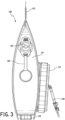
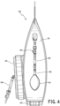
- a portable water filtration system 100 can be used in areas where potable water systems are not available.
- the system 100 includes a handle 105, a filter assembly 110 and a container vessel 115 that holds a volume of water.
- a pump 120 can be used to pressurize the vessel 115 to facilitate water flow through the filter assembly 110.
- the vessel 115 has a fill port that is covered by a cap 125.
- a retainer ring 130 is used to retain the cap 125.
- a sediment drain covered by a drain cap 135 is positioned at the bottom of the vessel 115.
- An outlet hose 140 is installed in an outlet of the filter assembly 110.
- the pump 120 includes a squeezable bulb 145, a pressure hose 150 and a valve actuated by a butterfly handle 155.
- the valve can seal the vessel 115 to maintain pressure.
- a protective cage 158 surrounds the filter assembly (not shown).
- the cage 158 includes a series of ribs that encircle the filter assembly. This protects the filter assembly against impact, such as, for example, if the container 100 is dropped.
- the filter assembly 110 include a carbon ring 160 and a series of corrugated filters 165 in a concentric ring. As will be described in more detail below, water flows from the outside to the inside of the concentric ring of filters to an exit port.
- the filter assembly 110 is positioned in a threaded collar 165 attached to the container 110.
- a threaded cap 170 is screwed into the threaded collar 165 to secure the filter assembly 110 in the container 110.
- a sealing ring 175 or gasket is positioned between the threaded cap and a lip 180 of the filter assembly 110 so that the filter assembly is clamped between the threaded collar 165 and the threaded cap 170 for a watertight seal ⁇
- the threaded cap is integrated into the filter assembly 110 so that the entire filter assembly 110 screws into the collar by rotating the integrated cap.
- the filter assembly 110 includes a circular intake cover 185, a sediment filter 190, a generally cylindrical wall 195, an inner circular wall 200 and a cover wall 205 over the concentric filters.
- the circular intake cover 185 has a series of ribs and openings that allow water to flow from the vessel 115 into the filter assembly 110.
- the inner circular wall 200 separates the filter assembly into a sediment filter chamber 210 and a concentric ring filter chamber 215.
- the inner circular wall 200 has a series of ports to allow water to flow from the sediment filter chamber 210 to the concentric ring filter chamber 215.
- the generally cylindrical wall 195 may have straight or parallel sides and a circular or oval cross-section in the shape or form of a cylinder. However, it may have other rectangular shafts or notches.
- the sediment filter 190 is positioned in a vertical orientation with respect to the height of the vessel 115. Thus, heavy sediment bypasses the sediment filter 190 and falls directly to the sediment drain thereby extending the life of the sediment filter 190.
- the embodiment shown in Fig. 11 has a series of four corrugated filters 220, 225, 230 and 235.
- the filters 220, 225, 230 and 235 are spaced apart by dividing walls 240, 245, and 250.
- each of the dividing walls 218, 240, 245, and 250 has ports or slots that allow the flow of water toward the center of the concentric rings.
- a circular outlet tube 255 is positioned at the center of the dividing walls 218, 240, 245, and 250.
- additional dividing walls may be added or dividing walls may not be used.
- One or more of the concentric filters 220, 225, 230 and 235 may be configured to remove suspended matter, microbiological matter and/or chemicals.
- a circular outlet tube 255 forces the water to change direction upward toward the sediment filter 190 and then down again through an outlet port 260 into an outlet chamber as shown by Arrow E. Water then flows down toward an exit port 265 in a direction to exit the container 100 as shown by Arrow F.
- a spiral flow agitator component 270 is positioned in the circular outlet tube 255.
- the agitator component 270 causes turbulence so that water has increased contact with a disinfectant media in the outlet tube 255.
- the agitator component may also include disinfection media.
- the filter material is designed with a larger range of pore sizes than that of a conventional filter.
- the range of pore sizes shown in Fig. 19 are generally larger than that shown in Fig. 20 , however, the range of pore sizes can overlap.
- Figs. 21 shows various filter media segment layers that make up the sediment filter.
- the range of pore sizes of the surface material making up each filter segment layer AAA, AA, A, B, C, D, E and F generally get smaller.
- some of the segment layers AA, A, B, C, E and F are made up of varying amounts of a first surface material sandwiching a second filter material.
- the range of pore sizes of the first surface material can be adjusted by adding or subtracting various layers of a filter media together, such as, for example, layers of a melt blown polypropylene (PP) web.
- a filter media such as, for example, layers of a melt blown polypropylene (PP) web.
- the degree of fiber-entanglement, fiber diameter and density of the melt blown web can also be used to vary effective pore sizes of the PP.
- spunbond fabric may be used in addition to or to replace the PP when, for example, additional strength is needed.
- segment layers AAA, AA, A, B, C and D include four individual layers that make up each of the segment layers.
- the four individual layers may have surfaces that are bonded to each other to make up the segment layer or they may be stacked on each other so that they contact adjacent individual layers without being bonded together.
- the surfaces of the individual layers are tacked to adjacent individual layers in discrete locations such as in the center of each layer and at the edges.
- the filter media segment layers AAA, AA, A, B, C, D, E and F are stacked together.
- Each segment AAA, AA, A, B, C, D, E and F is in contact with adjacent segment layers, but the surfaces of the segment layers are not bonded together.
- the filter media segment layers are stacked and cut together in a desired shape.
- the segment layers may be stacked, and an ultrasonic cutter may be used.
- a seal or bond at the edges of the segment layers may be formed during the cutting process.
- a form of heat welding may be used to bond the segment edges together.
- the edges of the segment layers can be clamped or bonded together with a plastic ring or silicone over molding to form the sediment filter.
- the sediment filter can be much denser at the edges while the center bulges outward at the top, bottom or both the top and bottom.
- segment layer AAA is shown in more detail with a multiple layer surface view, single layer surface view and a profile view. Each profile view is from the side with the filter media sandwiched between glass slides for illustration purposes only.
- Segment layer AAA is formed from multiple layers of PP that are bonded together. In one embodiment, four individual layers make up one segment layer AAA which is 100% PP with a density of 20 - 70 grams per square meter (GSM).
- the segment layers AA, A, B and C are illustrated by surface, cut-away, full stack profile and single layer profile views.
- the term full stack profile refers to the combinational of individual layers that make up the segment layer and single layer profile refers to an individual layer of the segment layer.
- the outer layers of each individual layer are formed from PP bonded to an inner layer formed from polyethylene terephthalate (PET) fibers.
- PET polyethylene terephthalate
- the outer PP layers dictate the range of pore sizes while the PET fibers provide a three-dimensional matrix of filter media with much less resistance to particle flow than the PP surface or outer layers.
- the PET fiber matrix allows sediment particles to travel in varying directions through the filter media as well as laterally. This provides a higher volume of particle loading in comparison to a filter with a more single directional flow through the filter media.
- the PET and PP fibers are bonded together to form each layer.
- segment layer AA includes a composition of 75% PET / 25% PP
- segment layer A includes a composition of 55% PET / 45% PP
- segment layer B includes a composition of 45% PET / 55% PP
- segment layer C includes a composition of 25% PET / 75% PP.
- Each segment layer AA, A, B and C may have a density of about 70 GSM.
- Each of the segment layers AA, A, B and C can be composed of three or more layers of individual sandwich structures of PP layers on each side of PET fibers.
- the outer PP layers exhibit randomly distributed pore size structure across the surface of a sheet which also is a micro three-dimensional structure. This helps maintain flow rate and prevent pressure drop.
- the inner PET layer is composed of fibers which create a further three-dimensional structure to allow better dust loading capacity whilst maintaining randomly distributed pore sizes which again helps prevent pressure drop and premature clogging.
- the PET layer generally has a lower density and has much more porosity than the PP layer.
- Multiple layers of the sandwich are stacked one on top of another to create a segment with more depth and hence more voids and more of a three-dimensional structure. These randomly distributed voids help to capture a range of particle sizes to prevent subsequent segment layers from clogging prematurely. Stacking of these layers helps create a more three-dimensional structure with multidirectional flow.
- Segment layer AA is made from PET fibers sandwiched between layers of PP. This "sandwich" is more open than subsequent segment layers and exhibits a larger pore size structure in general than subsequent segment layers but has a smaller pore size than previous segment layers.
- segment layer AA can be composed of three or more individual sandwich structures.
- the outer layers of each sandwich are composed of melt blown polypropylene which exhibits randomly distributed pore size structure across the surface of a sheet which is which also a micro three-dimensional structure. This helps maintain flow rate and prevent pressure drop.
- the inner layer is composed of polyethylene terephthalate fibers which create a further three-dimensional structure to allow better dust loading capacity whilst maintaining randomly distributed pore sizes which again helps prevent pressure drop and premature clogging.
- Multiple layers of the sandwich are stacked one on top of another to create a segment with more depth and hence more voids and more of a three-dimensional structure. These randomly distributed voids help to capture particle sizes to prevent subsequent segment layers from clogging prematurely. Stacking of these layers helps create a more three-dimensional structure with multidirectional flow.
- segment layer D is illustrated by in profile, stack profile and surface views.
- segment layer D has all PP individual sheets with a density of about 40 GSM that are bonded together into segment layer D.
- the PP sheet may have a depth of 0.5 - 2 mm.
- Multiple individual sheets are stacked to create a segment with depth and voids. These randomly distributed voids help to capture larger particle sizes above 3 microns to prevent the subsequent layers from clogging prematurely and causing a drop in pressure. This stacking helps creates a more three-dimensional filter segment with greater dust holding capacity and with multidirectional flow.
- segment layer E is shown in surface, cut away and profile views.
- Segment layer E includes PP on outer surfaces with pseudoboehmite sandwiched in-between.
- Pseudoboehmite is an aluminum compound with the chemical composition AIO. It consists of finely crystalline boehmite, but with a higher water content than in boehmite.
- Segment layer E can be composed of one or more layers of individual sandwich structures with a 6.25 mean micron pore size.
- the pseudoboehmite creates a further three-dimensional structure to allow better dust loading capacity whilst maintaining randomly distributed micro pore sizes which again helps prevent pressure drop and premature clogging. This helps maintain flow rate and prevent pressure drop with multidirectional flow.
- Powder activated carbon may also be incorporated in the inside of the sandwich for taste, odor contaminant reduction.
- segment layer F is shown in surface, cut away and profile views. Similar to segment layer E, segment layer F can be composed of includes PP on outer surfaces with pseudoboehmite sandwiched in-between, however, the individual sandwich structures have a much finer 1.25 micron mean pore size.
- filter media may be used instead of pseudoboehmite, such as, for example, very fine (small diameter), highly entangled and/or dense layers of PET fibers.
- Figs. 43 and 44 are photos of the full stack of segment layers AAA, AA, A, B, C, D and F shown in Figs. 21 - 23 mentioned above. All the segment layers are in contact with adjacent layers.
- the resulting sediment filter has can have a finer pore size and/or higher dust load capacity relative to conventional filters before the sediment filter gets clogged and loses its filtration capacity.
- a cylindrical sediment filter 300 is illustrated with filter media segment layers AAA', AA', A', B, C, D, E' and F' are configured as a concentric ring.
- Each segment AAA', AA', A', B', C', D', E' and F' are in contact with adjacent segment layers but the surfaces of adjacent segment layers are not bonded together.
- the composition of the segment layer may be similar to that described above with respect to Figs. 21 - 23 and 43 - 44 . In other embodiments, there may be more or less segment layers of different compositions.
- Fig. 48 illustrates the cylindrical sediment filter 300 in use.
- the cylindrical sediment filter 300 is installed in a filter casing 310.
- the filter casing has a water input line with water flowing into the filter casing shown by Arrow A.
- the bottom of the filter 300 is sealed or pressure fitted against the bottom of the casing such that water flows through the filter as shown by Arrow B.
- the water flows into an open channel at the center of the filter 300 and flows out of the casing case through output line 330 in the direction shown by Arrow C.
- Fig. 49 illustrates another embodiment of a sediment filter configured as a bag filter 350.
- the bag filter 350 includes multiple segment layers as that described above or may have another configuration of segment layers.
- the edges of the bag filter 350 may essentially be crimped or secured together by a round collar or may be heat bonded or glued together.
- the carbon ring 160 is replaced by an annular ring filter 510 that includes adsorption particles, such as, activated carbon granules, in a casing or enclosure.
- the filter 510 includes a first circular wall 515 and a second circular wall 520 mounted between a first annulas wall 525 and a second annul as wall 530.
- the internal volume of the annular ring filter 510 is filled with activated carbon granules.
- the first and second circular walls 515, 520 are permeable to water but retain the carbon granules.
- a first dividing wall 535 and a second dividing wall 540 is mounted between the first and second circular wall 515, 520 to divide the internal volume into first, second and third channels 545, 550, 555.
- a bisecting or termination wall 560 is attached between the first and second circular walls to the dividing walls to change the direct of water flow from a first direction in the first channel to a second direction in the second channel and to a third direction in a third channel.
- Protrusion walls 565 are mounted in the second channel with the protrusion walls partially obstructing the second channel thereby increasing turbulent water flow in the second channel.
- the protrusion walls include mating pairs of curling walls configured to cause a z-shaped or s-shaped water flow within the second channel.
- Each protrusion wall 565 is mounted to the dividing walls 535, 540.
- the protrusion walls 565 can be mounded to the annulas walls at a position in the second channel 555.
- the water enters the filter through the outer circular wall 515.
- the water flows in a first channel 550 until it reaches the end of the dividing wall 535 where it enters the second channel 555.
- the second channel 555 is filled with the protruding walls 565 that partially obstruct or change direction of water flow in the second channel 555.
- the resulting circuitous path results in more contact with the activated carbon granules.
- the water flows through the second channel 555 until it reaches the end of second dividing wall 540.
- the water is then in contact with the permeable inside filter wall 520.
- the water flows the permeable filter wall 520 to exits the annular filter ring 510 into the center of the ring.
- Some of the water also flows into the third channel 545 until it also exits through the permeable inside filter wall 520.
- the water may then enter other filters that are part of a concentric ring inside the annular ring filter 510.
Landscapes
- Chemical & Material Sciences (AREA)
- Chemical Kinetics & Catalysis (AREA)
- Life Sciences & Earth Sciences (AREA)
- Engineering & Computer Science (AREA)
- Environmental & Geological Engineering (AREA)
- Hydrology & Water Resources (AREA)
- Water Supply & Treatment (AREA)
- Organic Chemistry (AREA)
- Inorganic Chemistry (AREA)
- Ceramic Engineering (AREA)
- Geology (AREA)
- Filtering Materials (AREA)
- Water Treatment By Sorption (AREA)
- Filtration Of Liquid (AREA)
- Treatment Of Sludge (AREA)
- Electrical Discharge Machining, Electrochemical Machining, And Combined Machining (AREA)
- Separation Using Semi-Permeable Membranes (AREA)
- Excavating Of Shafts Or Tunnels (AREA)
Claims (13)
- Système de filtration d'eau (100), comprenant :un récipient de stockage (115) ayant un orifice de remplissage et un drain à sédiments et définissant un volume interne avec un passage de fluide entre l'orifice de remplissage et le drain à sédiments ;un boîtier de filtre comprenant une paroi de filtre cylindrique (195) avec une extrémité d'entrée et une extrémité de sortie ;un filtre à sédiments (190) disposé à l'intérieur de l'extrémité d'entrée et ayant une surface de filtre à sédiments faisant face à l'extrémité d'entrée, dans lequel une surface du filtre à sédiments (190) est sensiblement parallèle au passage de fluide entre l'orifice de remplissage et le drain à sédiments ;plus d'un filtre cylindrique (220, 225, 230, 235) à proximité de l'extrémité de sortie, le plus d'un filtre cylindrique (220, 225, 230, 235) ayant chacun une surface de filtre cylindrique, dans lequel la surface de filtre à sédiments est orthogonale à chaque surface de filtre cylindrique ; etun bouchon fileté (170) qui entoure l'extrémité de sortie de la paroi de filtre cylindrique (195) et conçu pour recevoir un collet fileté (165) sur le récipient de stockage (115), le bouchon fileté (170) ayant un orifice de sortie (265) relié de manière fluidique à un volume à l'intérieur d'une surface de filtre cylindrique la plus intérieure ; dans lequel au moins une partie du boîtier de filtre est positionnée à l'intérieur du volume interne du récipient de stockage (115).
- Système de filtration d'eau selon la revendication 1, dans lequel le filtre à sédiments (190) comprend un disque généralement circulaire.
- Système de filtration d'eau selon la revendication 1, dans lequel le plus d'un filtre cylindrique (220, 225, 230, 235) comprend plus d'un filtre cylindrique dans un anneau concentrique.
- Système de filtration d'eau selon la revendication 1, dans lequel un premier canal et un deuxième canal relient de manière fluidique le filtre à sédiments (190) au plus d'un filtre cylindrique (220, 225, 230, 235) et dans lequel le premier canal a un premier axe central qui est orthogonal à un axe central de filtre cylindrique de l'au moins un filtre cylindrique (220, 225, 230, 235).
- Système de filtration d'eau selon la revendication 4, dans lequel un second axe central du deuxième canal est parallèle à l'axe central de filtre cylindrique.
- Système de filtration d'eau selon la revendication 1, dans lequelle plus d'un filtre cylindrique (220, 225, 230, 235) comprend en outre un filtre annulaire (510) ayant une première paroi circulaire (515) et une seconde paroi circulaire (520) montées entre une première paroi annulaire (525) et une seconde paroi annulaire (530) qui définissent un volume interne ;le filtre annulaire (510) est rempli de granulés de charbon actif ; etles première et seconde parois circulaires (515, 520) sont perméables à l'eau mais retiennent les granulés de carbone.
- Système de filtration d'eau selon la revendication 6, comprenant en outre :une paire de parois de séparation (535, 540) montées entre la première et la seconde paroi circulaire (515, 520) pour diviser le volume interne en un premier, un deuxième et un troisième canal (545, 550, 555) ;une paroi bissectrice attachée entre la première et la seconde paroi circulaire (515, 520) pour modifier la direction de l'écoulement de l'eau d'une première direction dans le premier canal (545) à une seconde direction dans le deuxième canal (550) ; etplus d'une paroi en saillie (565) montée dans le deuxième canal (550), dans lequel la paroi en saillie (565) obstrue partiellement le deuxième canal (550), augmentant ainsi l'écoulement turbulent de l'eau dans le deuxième canal (550).
- Système de filtration d'eau selon la revendication 7, dans lequel la paroi en saillie (565) comprend une paire de parois incurvées conçues pour provoquer un écoulement de l'eau en forme de z ou de s à l'intérieur du deuxième canal.
- Système de filtration d'eau selon la revendication 8, dans lequel chaque paroi en saillie (565) est montée sur l'une ou les deux premières parois annulaires (525) et sur la deuxième paroi annulaire (530).
- Système de filtration d'eau selon la revendication 6, dans lequel le plus d'un filtre cylindrique (220, 225, 230, 235) comprend une pluralité de filtres à milieu à plis conçus en un anneau concentrique à l'intérieur du filtre annulaire.
- Système de filtration d'eau selon la revendication 10, comprenant en outre un tube de sortie au centre de l'anneau concentrique, dans lequel le tube de sortie comprend une paroi qui provoque un changement de direction du flux de l'eau d'une direction qui est orthogonale à l'axe central des filtres à milieu à plis à une direction qui est parallèle à l'axe central des filtres à milieu à plis.
- Système de filtration selon la revendication 1, dans lequel le récipient de stockage (115) comprend une paroi sensiblement verticale avec une ouverture, dans lequel le boîtier de filtre est reçu à l'intérieur de l'ouverture de la paroi verticale.
- Système de filtration selon la revendication 1, comprenant en outre le récipient de stockage (115) ayant une paroi sensiblement verticale et la surface de filtre à sédiments est sensiblement parallèle à la paroi verticale, de telle sorte que des particules non flottantes contournent le filtre à sédiments (190).
Priority Applications (1)
| Application Number | Priority Date | Filing Date | Title |
|---|---|---|---|
| EP25159961.9A EP4570341A3 (fr) | 2019-11-15 | 2020-11-16 | Système de filtration d'eau |
Applications Claiming Priority (4)
| Application Number | Priority Date | Filing Date | Title |
|---|---|---|---|
| US201962936111P | 2019-11-15 | 2019-11-15 | |
| US201962948784P | 2019-12-16 | 2019-12-16 | |
| US16/735,615 US10994229B1 (en) | 2019-11-15 | 2020-01-06 | Water filtration system |
| PCT/US2020/060798 WO2021097458A1 (fr) | 2019-11-15 | 2020-11-16 | Système de filtration d'eau |
Related Child Applications (1)
| Application Number | Title | Priority Date | Filing Date |
|---|---|---|---|
| EP25159961.9A Division EP4570341A3 (fr) | 2019-11-15 | 2020-11-16 | Système de filtration d'eau |
Publications (4)
| Publication Number | Publication Date |
|---|---|
| EP4058172A1 EP4058172A1 (fr) | 2022-09-21 |
| EP4058172A4 EP4058172A4 (fr) | 2023-11-22 |
| EP4058172B1 true EP4058172B1 (fr) | 2025-02-26 |
| EP4058172C0 EP4058172C0 (fr) | 2025-02-26 |
Family
ID=75689523
Family Applications (2)
| Application Number | Title | Priority Date | Filing Date |
|---|---|---|---|
| EP20887158.2A Active EP4058172B1 (fr) | 2019-11-15 | 2020-11-16 | Système de filtration d'eau |
| EP25159961.9A Pending EP4570341A3 (fr) | 2019-11-15 | 2020-11-16 | Système de filtration d'eau |
Family Applications After (1)
| Application Number | Title | Priority Date | Filing Date |
|---|---|---|---|
| EP25159961.9A Pending EP4570341A3 (fr) | 2019-11-15 | 2020-11-16 | Système de filtration d'eau |
Country Status (13)
| Country | Link |
|---|---|
| US (2) | US20210146282A1 (fr) |
| EP (2) | EP4058172B1 (fr) |
| JP (2) | JP2023502980A (fr) |
| KR (2) | KR20230162994A (fr) |
| CN (2) | CN117303661A (fr) |
| AU (1) | AU2020382668A1 (fr) |
| BR (1) | BR112022009278A2 (fr) |
| CA (1) | CA3161945A1 (fr) |
| IL (1) | IL292971A (fr) |
| MX (1) | MX2022005803A (fr) |
| PH (1) | PH12022551187A1 (fr) |
| WO (1) | WO2021097458A1 (fr) |
| ZA (1) | ZA202206547B (fr) |
Families Citing this family (2)
| Publication number | Priority date | Publication date | Assignee | Title |
|---|---|---|---|---|
| US20210147252A1 (en) * | 2019-11-15 | 2021-05-20 | Tech 23 Limited | Water filtration system |
| US11331616B2 (en) * | 2020-09-25 | 2022-05-17 | Mark Henderson | Pool filter assembly |
Family Cites Families (31)
| Publication number | Priority date | Publication date | Assignee | Title |
|---|---|---|---|---|
| US3209916A (en) * | 1961-10-04 | 1965-10-05 | Briggs Filtration Company | Filter construction |
| US4828698A (en) * | 1986-03-07 | 1989-05-09 | Pall Corporation | Filtering apparatus |
| US5017286A (en) * | 1990-03-05 | 1991-05-21 | Heiligman Randy B | Faucet-mounted water filter with wall inlet and annular chamber |
| US5266196A (en) * | 1991-07-19 | 1993-11-30 | Mountain Safety Research, Inc. | Water filter |
| US5259954A (en) | 1991-12-16 | 1993-11-09 | Sepratech, Inc. | Portable intravenous solution preparation apparatus and method |
| US5824232A (en) | 1996-04-15 | 1998-10-20 | Filtration Technologies Corporation | Corrugated filter sheet configured into a cylindrical filter media having near circular concentric channels |
| JPH10113507A (ja) | 1996-10-08 | 1998-05-06 | Japan Organo Co Ltd | プリーツ型カートリッジフィルタ |
| CA2346792A1 (fr) | 1998-10-08 | 2000-04-13 | Cuno Incorporated | Unite de filtrage |
| US20050035041A1 (en) * | 2001-08-10 | 2005-02-17 | Nohren John E. | Hollow fiber membrane filters in various containers |
| US6464870B1 (en) | 2000-08-08 | 2002-10-15 | Kuss Corporation | Filter assembly having plastic mesh conductive surround |
| US7601262B1 (en) | 2001-06-22 | 2009-10-13 | Argonide Corporation | Sub-micron filter |
| US20040149647A1 (en) * | 2001-12-20 | 2004-08-05 | Filtration Technology Corporation | Filter element flow diverter barrier and method |
| JP2005523144A (ja) | 2002-04-19 | 2005-08-04 | キュノ、インコーポレーテッド | 封入フィルター・カートリッジ |
| US6962660B2 (en) * | 2002-09-25 | 2005-11-08 | Master Spas, Inc. | Fluid filter system with secondary flow path for augmented filtration |
| US20040206682A1 (en) * | 2003-04-18 | 2004-10-21 | Thomas Hamlin | Filter assembly utilizing carbon block and pleated filter element |
| EP1651327A1 (fr) * | 2003-07-02 | 2006-05-03 | Dma Sorption Aps | Filtre |
| WO2006031838A1 (fr) | 2004-09-11 | 2006-03-23 | Randall Krafft | Filtre a eau compact |
| US7390343B2 (en) | 2005-09-12 | 2008-06-24 | Argonide Corporation | Drinking water filtration device |
| US7862720B2 (en) * | 2006-08-09 | 2011-01-04 | Aquamira Technologies, Inc. | Portable filtration system |
| US8231794B2 (en) * | 2007-07-05 | 2012-07-31 | Spintek Filtration, Inc. | Water filtration system |
| US7618480B2 (en) | 2007-07-16 | 2009-11-17 | Flair Corporation | Filter assembly and method |
| CN101784322B (zh) * | 2007-08-07 | 2014-03-12 | 3M创新有限公司 | 液体过滤系统 |
| US8287729B2 (en) * | 2008-04-28 | 2012-10-16 | California Polytechnic Corporation | Field water purification system |
| WO2009152291A1 (fr) | 2008-06-11 | 2009-12-17 | Argonide Corporation | Dispositif de chromatographie à phase stationnaire comprenant un milieu de nano alumine |
| KR100884847B1 (ko) * | 2008-09-29 | 2009-02-20 | 윤명순 | 정수기용 필터 |
| US8701895B2 (en) | 2010-05-11 | 2014-04-22 | Selecto, Inc. | Fluid purification media and systems and methods of using same |
| EP2609037B1 (fr) * | 2010-08-24 | 2014-06-04 | Unilever N.V. | Dispositif d'épuration d'eau comprenant un filtre alimenté par gravité |
| ES2905079T3 (es) * | 2012-04-09 | 2022-04-07 | Lifesaver Ip Ltd | Recipiente para agua y módulo de filtro de fibra hueca para el mismo |
| US9162167B2 (en) * | 2012-04-26 | 2015-10-20 | Aquamira Technologies, Inc. | Simplified filter |
| EP2866915A1 (fr) | 2012-06-27 | 2015-05-06 | Argonide Corporation | Sorbant siliceux aluminé et dispositif de purification de l'eau l'incorporant |
| US10913661B2 (en) * | 2016-08-22 | 2021-02-09 | Tender Corporation | Multi-stage filter assembly |
-
2020
- 2020-01-06 US US16/735,629 patent/US20210146282A1/en not_active Abandoned
- 2020-01-06 US US16/735,615 patent/US10994229B1/en active Active - Reinstated
- 2020-11-16 MX MX2022005803A patent/MX2022005803A/es unknown
- 2020-11-16 WO PCT/US2020/060798 patent/WO2021097458A1/fr not_active Ceased
- 2020-11-16 CN CN202311503384.4A patent/CN117303661A/zh active Pending
- 2020-11-16 PH PH1/2022/551187A patent/PH12022551187A1/en unknown
- 2020-11-16 CN CN202080079231.XA patent/CN114728219A/zh active Pending
- 2020-11-16 KR KR1020237039023A patent/KR20230162994A/ko active Pending
- 2020-11-16 BR BR112022009278A patent/BR112022009278A2/pt unknown
- 2020-11-16 JP JP2022528547A patent/JP2023502980A/ja active Pending
- 2020-11-16 CA CA3161945A patent/CA3161945A1/fr active Pending
- 2020-11-16 EP EP20887158.2A patent/EP4058172B1/fr active Active
- 2020-11-16 EP EP25159961.9A patent/EP4570341A3/fr active Pending
- 2020-11-16 AU AU2020382668A patent/AU2020382668A1/en active Pending
- 2020-11-16 KR KR1020227019649A patent/KR20220097993A/ko active Pending
- 2020-11-16 IL IL292971A patent/IL292971A/en unknown
-
2022
- 2022-06-13 ZA ZA2022/06547A patent/ZA202206547B/en unknown
-
2023
- 2023-11-23 JP JP2023198701A patent/JP7839563B2/ja active Active
Also Published As
| Publication number | Publication date |
|---|---|
| MX2022005803A (es) | 2022-10-07 |
| CA3161945A1 (fr) | 2021-05-20 |
| IL292971A (en) | 2022-07-01 |
| US20210146282A1 (en) | 2021-05-20 |
| KR20230162994A (ko) | 2023-11-29 |
| AU2020382668A1 (en) | 2022-06-30 |
| WO2021097458A1 (fr) | 2021-05-20 |
| JP2023502980A (ja) | 2023-01-26 |
| EP4058172A4 (fr) | 2023-11-22 |
| ZA202206547B (en) | 2024-01-31 |
| CN117303661A (zh) | 2023-12-29 |
| EP4058172A1 (fr) | 2022-09-21 |
| JP7839563B2 (ja) | 2026-04-02 |
| EP4570341A2 (fr) | 2025-06-18 |
| PH12022551187A1 (en) | 2023-10-09 |
| BR112022009278A2 (pt) | 2022-08-02 |
| JP2024009222A (ja) | 2024-01-19 |
| US20210146283A1 (en) | 2021-05-20 |
| CN114728219A (zh) | 2022-07-08 |
| US10994229B1 (en) | 2021-05-04 |
| KR20220097993A (ko) | 2022-07-08 |
| EP4570341A3 (fr) | 2025-08-13 |
| EP4058172C0 (fr) | 2025-02-26 |
Similar Documents
| Publication | Publication Date | Title |
|---|---|---|
| JP5582194B2 (ja) | 浄水カートリッジ及び浄水器 | |
| RU2262976C1 (ru) | Устройство фильтрационное | |
| JP7839563B2 (ja) | 水ろ過システム | |
| EP2219765A1 (fr) | Filtre avec composants de milieux extérieur et intérieur et procédé de filtration | |
| US11053137B1 (en) | Water filter cartridge | |
| US20250187945A1 (en) | Filter System | |
| US11376529B2 (en) | Particle filter system | |
| JPWO2007122909A1 (ja) | プリーツ型フィルタカートリッジ | |
| US20210147252A1 (en) | Water filtration system | |
| JP5433704B2 (ja) | 浄水カートリッジ | |
| HK40079134A (en) | Water filtration system | |
| JP4299522B2 (ja) | 浄水器用カートリッジ及び浄水器 | |
| JP2023060955A (ja) | 浄水器用カートリッジおよび浄水器 | |
| KR101957683B1 (ko) | 카본필터 | |
| EP2647414A1 (fr) | Ensemble pour former un composant d'un dispositif de traitement d'un fluide | |
| KR101947998B1 (ko) | 카본필터 | |
| KR20060042880A (ko) | 정수 카트리지 | |
| JP5081749B2 (ja) | 浄水器用カートリッジ | |
| JP5081750B2 (ja) | 浄水器用カートリッジ | |
| CN105174535A (zh) | 净水滤筒以及净水器 | |
| US20080257801A1 (en) | Device For Filtering Solid Particles For Liquids Containing Such Particles | |
| JP2020131152A (ja) | 浄水カートリッジ | |
| JP2003062561A (ja) | 浄水器用カートリッジ | |
| JPH03127685A (ja) | 浄水器 |
Legal Events
| Date | Code | Title | Description |
|---|---|---|---|
| STAA | Information on the status of an ep patent application or granted ep patent |
Free format text: STATUS: THE INTERNATIONAL PUBLICATION HAS BEEN MADE |
|
| PUAI | Public reference made under article 153(3) epc to a published international application that has entered the european phase |
Free format text: ORIGINAL CODE: 0009012 |
|
| STAA | Information on the status of an ep patent application or granted ep patent |
Free format text: STATUS: REQUEST FOR EXAMINATION WAS MADE |
|
| 17P | Request for examination filed |
Effective date: 20220607 |
|
| AK | Designated contracting states |
Kind code of ref document: A1 Designated state(s): AL AT BE BG CH CY CZ DE DK EE ES FI FR GB GR HR HU IE IS IT LI LT LU LV MC MK MT NL NO PL PT RO RS SE SI SK SM TR |
|
| DAV | Request for validation of the european patent (deleted) | ||
| DAX | Request for extension of the european patent (deleted) | ||
| A4 | Supplementary search report drawn up and despatched |
Effective date: 20231019 |
|
| RIC1 | Information provided on ipc code assigned before grant |
Ipc: C02F 1/42 20060101ALI20231013BHEP Ipc: C02F 1/00 20060101ALI20231013BHEP Ipc: B01D 39/16 20060101ALI20231013BHEP Ipc: B01D 29/92 20060101ALI20231013BHEP Ipc: B01D 35/30 20060101ALI20231013BHEP Ipc: B01D 29/86 20060101ALI20231013BHEP Ipc: B01D 29/58 20060101ALI20231013BHEP Ipc: B01D 29/21 20060101ALI20231013BHEP Ipc: B01D 29/15 20060101ALI20231013BHEP Ipc: B01D 29/33 20060101ALI20231013BHEP Ipc: B01D 36/02 20060101ALI20231013BHEP Ipc: B01D 35/26 20060101ALI20231013BHEP Ipc: C02F 1/28 20060101ALI20231013BHEP Ipc: C02F 1/52 20060101ALI20231013BHEP Ipc: B01D 25/00 20060101AFI20231013BHEP |
|
| REG | Reference to a national code |
Ref country code: DE Ref legal event code: R079 Ipc: C02F0001520000 Ref country code: DE Ref legal event code: R079 Ref document number: 602020046983 Country of ref document: DE Free format text: PREVIOUS MAIN CLASS: B01D0025000000 Ipc: C02F0001520000 |
|
| GRAP | Despatch of communication of intention to grant a patent |
Free format text: ORIGINAL CODE: EPIDOSNIGR1 |
|
| STAA | Information on the status of an ep patent application or granted ep patent |
Free format text: STATUS: GRANT OF PATENT IS INTENDED |
|
| RIC1 | Information provided on ipc code assigned before grant |
Ipc: B01D 25/00 20060101ALI20240902BHEP Ipc: C02F 1/42 20060101ALI20240902BHEP Ipc: C02F 1/00 20060101ALI20240902BHEP Ipc: B01D 39/16 20060101ALI20240902BHEP Ipc: B01D 29/92 20060101ALI20240902BHEP Ipc: B01D 35/30 20060101ALI20240902BHEP Ipc: B01D 29/86 20060101ALI20240902BHEP Ipc: B01D 29/58 20060101ALI20240902BHEP Ipc: B01D 29/21 20060101ALI20240902BHEP Ipc: B01D 29/15 20060101ALI20240902BHEP Ipc: B01D 29/33 20060101ALI20240902BHEP Ipc: B01D 36/02 20060101ALI20240902BHEP Ipc: B01D 35/26 20060101ALI20240902BHEP Ipc: C02F 1/28 20060101ALI20240902BHEP Ipc: C02F 1/52 20060101AFI20240902BHEP |
|
| INTG | Intention to grant announced |
Effective date: 20240923 |
|
| GRAS | Grant fee paid |
Free format text: ORIGINAL CODE: EPIDOSNIGR3 |
|
| GRAA | (expected) grant |
Free format text: ORIGINAL CODE: 0009210 |
|
| STAA | Information on the status of an ep patent application or granted ep patent |
Free format text: STATUS: THE PATENT HAS BEEN GRANTED |
|
| AK | Designated contracting states |
Kind code of ref document: B1 Designated state(s): AL AT BE BG CH CY CZ DE DK EE ES FI FR GB GR HR HU IE IS IT LI LT LU LV MC MK MT NL NO PL PT RO RS SE SI SK SM TR |
|
| REG | Reference to a national code |
Ref country code: GB Ref legal event code: FG4D |
|
| REG | Reference to a national code |
Ref country code: CH Ref legal event code: EP |
|
| REG | Reference to a national code |
Ref country code: DE Ref legal event code: R096 Ref document number: 602020046983 Country of ref document: DE |
|
| REG | Reference to a national code |
Ref country code: IE Ref legal event code: FG4D |
|
| U01 | Request for unitary effect filed |
Effective date: 20250227 |
|
| U07 | Unitary effect registered |
Designated state(s): AT BE BG DE DK EE FI FR IT LT LU LV MT NL PT RO SE SI Effective date: 20250310 |
|
| PG25 | Lapsed in a contracting state [announced via postgrant information from national office to epo] |
Ref country code: RS Free format text: LAPSE BECAUSE OF FAILURE TO SUBMIT A TRANSLATION OF THE DESCRIPTION OR TO PAY THE FEE WITHIN THE PRESCRIBED TIME-LIMIT Effective date: 20250526 |
|
| PG25 | Lapsed in a contracting state [announced via postgrant information from national office to epo] |
Ref country code: PL Free format text: LAPSE BECAUSE OF FAILURE TO SUBMIT A TRANSLATION OF THE DESCRIPTION OR TO PAY THE FEE WITHIN THE PRESCRIBED TIME-LIMIT Effective date: 20250226 |
|
| PG25 | Lapsed in a contracting state [announced via postgrant information from national office to epo] |
Ref country code: ES Free format text: LAPSE BECAUSE OF FAILURE TO SUBMIT A TRANSLATION OF THE DESCRIPTION OR TO PAY THE FEE WITHIN THE PRESCRIBED TIME-LIMIT Effective date: 20250226 |
|
| PG25 | Lapsed in a contracting state [announced via postgrant information from national office to epo] |
Ref country code: NO Free format text: LAPSE BECAUSE OF FAILURE TO SUBMIT A TRANSLATION OF THE DESCRIPTION OR TO PAY THE FEE WITHIN THE PRESCRIBED TIME-LIMIT Effective date: 20250526 Ref country code: IS Free format text: LAPSE BECAUSE OF FAILURE TO SUBMIT A TRANSLATION OF THE DESCRIPTION OR TO PAY THE FEE WITHIN THE PRESCRIBED TIME-LIMIT Effective date: 20250626 |
|
| PG25 | Lapsed in a contracting state [announced via postgrant information from national office to epo] |
Ref country code: HR Free format text: LAPSE BECAUSE OF FAILURE TO SUBMIT A TRANSLATION OF THE DESCRIPTION OR TO PAY THE FEE WITHIN THE PRESCRIBED TIME-LIMIT Effective date: 20250226 |
|
| PG25 | Lapsed in a contracting state [announced via postgrant information from national office to epo] |
Ref country code: GR Free format text: LAPSE BECAUSE OF FAILURE TO SUBMIT A TRANSLATION OF THE DESCRIPTION OR TO PAY THE FEE WITHIN THE PRESCRIBED TIME-LIMIT Effective date: 20250527 |
|
| PG25 | Lapsed in a contracting state [announced via postgrant information from national office to epo] |
Ref country code: SM Free format text: LAPSE BECAUSE OF FAILURE TO SUBMIT A TRANSLATION OF THE DESCRIPTION OR TO PAY THE FEE WITHIN THE PRESCRIBED TIME-LIMIT Effective date: 20250226 |
|
| PG25 | Lapsed in a contracting state [announced via postgrant information from national office to epo] |
Ref country code: CZ Free format text: LAPSE BECAUSE OF FAILURE TO SUBMIT A TRANSLATION OF THE DESCRIPTION OR TO PAY THE FEE WITHIN THE PRESCRIBED TIME-LIMIT Effective date: 20250226 |
|
| PG25 | Lapsed in a contracting state [announced via postgrant information from national office to epo] |
Ref country code: SK Free format text: LAPSE BECAUSE OF FAILURE TO SUBMIT A TRANSLATION OF THE DESCRIPTION OR TO PAY THE FEE WITHIN THE PRESCRIBED TIME-LIMIT Effective date: 20250226 |
|
| PLBE | No opposition filed within time limit |
Free format text: ORIGINAL CODE: 0009261 |
|
| STAA | Information on the status of an ep patent application or granted ep patent |
Free format text: STATUS: NO OPPOSITION FILED WITHIN TIME LIMIT |
|
| 26N | No opposition filed |
Effective date: 20251127 |