EP4058209B1 - Faltenbalgpumpe mit abwärtssperre - Google Patents
Faltenbalgpumpe mit abwärtssperre Download PDFInfo
- Publication number
- EP4058209B1 EP4058209B1 EP20804294.5A EP20804294A EP4058209B1 EP 4058209 B1 EP4058209 B1 EP 4058209B1 EP 20804294 A EP20804294 A EP 20804294A EP 4058209 B1 EP4058209 B1 EP 4058209B1
- Authority
- EP
- European Patent Office
- Prior art keywords
- pump
- insert
- housing
- actuator
- projections
- Prior art date
- Legal status (The legal status is an assumption and is not a legal conclusion. Google has not performed a legal analysis and makes no representation as to the accuracy of the status listed.)
- Active
Links
Images







Classifications
-
- B—PERFORMING OPERATIONS; TRANSPORTING
- B05—SPRAYING OR ATOMISING IN GENERAL; APPLYING FLUENT MATERIALS TO SURFACES, IN GENERAL
- B05B—SPRAYING APPARATUS; ATOMISING APPARATUS; NOZZLES
- B05B11/00—Single-unit hand-held apparatus in which flow of contents is produced by the muscular force of the operator at the moment of use
- B05B11/0005—Components or details
-
- B—PERFORMING OPERATIONS; TRANSPORTING
- B05—SPRAYING OR ATOMISING IN GENERAL; APPLYING FLUENT MATERIALS TO SURFACES, IN GENERAL
- B05B—SPRAYING APPARATUS; ATOMISING APPARATUS; NOZZLES
- B05B11/00—Single-unit hand-held apparatus in which flow of contents is produced by the muscular force of the operator at the moment of use
- B05B11/0005—Components or details
- B05B11/0037—Containers
- B05B11/0039—Containers associated with means for compensating the pressure difference between the ambient pressure and the pressure inside the container, e.g. pressure relief means
- B05B11/0044—Containers associated with means for compensating the pressure difference between the ambient pressure and the pressure inside the container, e.g. pressure relief means compensating underpressure by ingress of atmospheric air into the container, i.e. with venting means
-
- B—PERFORMING OPERATIONS; TRANSPORTING
- B05—SPRAYING OR ATOMISING IN GENERAL; APPLYING FLUENT MATERIALS TO SURFACES, IN GENERAL
- B05B—SPRAYING APPARATUS; ATOMISING APPARATUS; NOZZLES
- B05B11/00—Single-unit hand-held apparatus in which flow of contents is produced by the muscular force of the operator at the moment of use
- B05B11/01—Single-unit hand-held apparatus in which flow of contents is produced by the muscular force of the operator at the moment of use characterised by the means producing the flow
- B05B11/10—Pump arrangements for transferring the contents from the container to a pump chamber by a sucking effect and forcing the contents out through the dispensing nozzle
- B05B11/1001—Piston pumps
-
- B—PERFORMING OPERATIONS; TRANSPORTING
- B05—SPRAYING OR ATOMISING IN GENERAL; APPLYING FLUENT MATERIALS TO SURFACES, IN GENERAL
- B05B—SPRAYING APPARATUS; ATOMISING APPARATUS; NOZZLES
- B05B11/00—Single-unit hand-held apparatus in which flow of contents is produced by the muscular force of the operator at the moment of use
- B05B11/01—Single-unit hand-held apparatus in which flow of contents is produced by the muscular force of the operator at the moment of use characterised by the means producing the flow
- B05B11/10—Pump arrangements for transferring the contents from the container to a pump chamber by a sucking effect and forcing the contents out through the dispensing nozzle
- B05B11/1001—Piston pumps
- B05B11/1023—Piston pumps having an outlet valve opened by deformation or displacement of the piston relative to its actuating stem
-
- B—PERFORMING OPERATIONS; TRANSPORTING
- B05—SPRAYING OR ATOMISING IN GENERAL; APPLYING FLUENT MATERIALS TO SURFACES, IN GENERAL
- B05B—SPRAYING APPARATUS; ATOMISING APPARATUS; NOZZLES
- B05B11/00—Single-unit hand-held apparatus in which flow of contents is produced by the muscular force of the operator at the moment of use
- B05B11/01—Single-unit hand-held apparatus in which flow of contents is produced by the muscular force of the operator at the moment of use characterised by the means producing the flow
- B05B11/10—Pump arrangements for transferring the contents from the container to a pump chamber by a sucking effect and forcing the contents out through the dispensing nozzle
- B05B11/1028—Pumps having a pumping chamber with a deformable wall
- B05B11/1035—Pumps having a pumping chamber with a deformable wall the pumping chamber being a bellow
-
- B—PERFORMING OPERATIONS; TRANSPORTING
- B05—SPRAYING OR ATOMISING IN GENERAL; APPLYING FLUENT MATERIALS TO SURFACES, IN GENERAL
- B05B—SPRAYING APPARATUS; ATOMISING APPARATUS; NOZZLES
- B05B11/00—Single-unit hand-held apparatus in which flow of contents is produced by the muscular force of the operator at the moment of use
- B05B11/01—Single-unit hand-held apparatus in which flow of contents is produced by the muscular force of the operator at the moment of use characterised by the means producing the flow
- B05B11/10—Pump arrangements for transferring the contents from the container to a pump chamber by a sucking effect and forcing the contents out through the dispensing nozzle
- B05B11/1042—Components or details
- B05B11/1043—Sealing or attachment arrangements between pump and container
- B05B11/1046—Sealing or attachment arrangements between pump and container the pump chamber being arranged substantially coaxially to the neck of the container
- B05B11/1047—Sealing or attachment arrangements between pump and container the pump chamber being arranged substantially coaxially to the neck of the container the pump being preassembled as an independent unit before being mounted on the container
-
- B—PERFORMING OPERATIONS; TRANSPORTING
- B05—SPRAYING OR ATOMISING IN GENERAL; APPLYING FLUENT MATERIALS TO SURFACES, IN GENERAL
- B05B—SPRAYING APPARATUS; ATOMISING APPARATUS; NOZZLES
- B05B11/00—Single-unit hand-held apparatus in which flow of contents is produced by the muscular force of the operator at the moment of use
- B05B11/01—Single-unit hand-held apparatus in which flow of contents is produced by the muscular force of the operator at the moment of use characterised by the means producing the flow
- B05B11/10—Pump arrangements for transferring the contents from the container to a pump chamber by a sucking effect and forcing the contents out through the dispensing nozzle
- B05B11/1042—Components or details
- B05B11/1059—Means for locking a pump or its actuation means in a fixed position
-
- B—PERFORMING OPERATIONS; TRANSPORTING
- B05—SPRAYING OR ATOMISING IN GENERAL; APPLYING FLUENT MATERIALS TO SURFACES, IN GENERAL
- B05B—SPRAYING APPARATUS; ATOMISING APPARATUS; NOZZLES
- B05B11/00—Single-unit hand-held apparatus in which flow of contents is produced by the muscular force of the operator at the moment of use
- B05B11/01—Single-unit hand-held apparatus in which flow of contents is produced by the muscular force of the operator at the moment of use characterised by the means producing the flow
- B05B11/10—Pump arrangements for transferring the contents from the container to a pump chamber by a sucking effect and forcing the contents out through the dispensing nozzle
- B05B11/1042—Components or details
- B05B11/1059—Means for locking a pump or its actuation means in a fixed position
- B05B11/106—Means for locking a pump or its actuation means in a fixed position in a retracted position, e.g. in an end-of-dispensing-stroke position
-
- B—PERFORMING OPERATIONS; TRANSPORTING
- B05—SPRAYING OR ATOMISING IN GENERAL; APPLYING FLUENT MATERIALS TO SURFACES, IN GENERAL
- B05B—SPRAYING APPARATUS; ATOMISING APPARATUS; NOZZLES
- B05B11/00—Single-unit hand-held apparatus in which flow of contents is produced by the muscular force of the operator at the moment of use
- B05B11/01—Single-unit hand-held apparatus in which flow of contents is produced by the muscular force of the operator at the moment of use characterised by the means producing the flow
- B05B11/10—Pump arrangements for transferring the contents from the container to a pump chamber by a sucking effect and forcing the contents out through the dispensing nozzle
- B05B11/1042—Components or details
- B05B11/1073—Springs
- B05B11/1074—Springs located outside pump chambers
-
- B—PERFORMING OPERATIONS; TRANSPORTING
- B05—SPRAYING OR ATOMISING IN GENERAL; APPLYING FLUENT MATERIALS TO SURFACES, IN GENERAL
- B05B—SPRAYING APPARATUS; ATOMISING APPARATUS; NOZZLES
- B05B11/00—Single-unit hand-held apparatus in which flow of contents is produced by the muscular force of the operator at the moment of use
- B05B11/01—Single-unit hand-held apparatus in which flow of contents is produced by the muscular force of the operator at the moment of use characterised by the means producing the flow
- B05B11/10—Pump arrangements for transferring the contents from the container to a pump chamber by a sucking effect and forcing the contents out through the dispensing nozzle
- B05B11/1042—Components or details
- B05B11/1073—Springs
- B05B11/1077—Springs characterised by a particular shape or material
-
- F—MECHANICAL ENGINEERING; LIGHTING; HEATING; WEAPONS; BLASTING
- F04—POSITIVE - DISPLACEMENT MACHINES FOR LIQUIDS; PUMPS FOR LIQUIDS OR ELASTIC FLUIDS
- F04B—POSITIVE-DISPLACEMENT MACHINES FOR LIQUIDS; PUMPS
- F04B19/00—Machines or pumps having pertinent characteristics not provided for in, or of interest apart from, groups F04B1/00 - F04B17/00
- F04B19/04—Pumps for special use
-
- F—MECHANICAL ENGINEERING; LIGHTING; HEATING; WEAPONS; BLASTING
- F04—POSITIVE - DISPLACEMENT MACHINES FOR LIQUIDS; PUMPS FOR LIQUIDS OR ELASTIC FLUIDS
- F04B—POSITIVE-DISPLACEMENT MACHINES FOR LIQUIDS; PUMPS
- F04B43/00—Machines, pumps, or pumping installations having flexible working members
- F04B43/0009—Special features
Definitions
- This application relates generally to pump dispensers and, more specifically, to a bellows pump made from recyclable materials (e.g., a single grade of polymeric plastic or a combination of such plastics that are compatible with and amenable to current recycling programs) in which a lockdown function allows shipment of the pump without compression of the bellows itself.
- recyclable materials e.g., a single grade of polymeric plastic or a combination of such plastics that are compatible with and amenable to current recycling programs
- Containers for everyday household fluid products such as soaps, cleaners, oils, consumable liquids, and the like, can be outfitted with dispensing pumps to improve a consumer's ability to access and use the fluid.
- Dispensing pumps of this type usually rely upon a reciprocating pump, driven by a compressible biasing member.
- dispenser pumps have used metal springs to provide the biasing force necessary to drive the reciprocating action.
- Metal springs were considered particularly useful because they much less prone to fatigue, wear, and failure in comparison to existing non-metal alternatives, such as plastic coils.
- metal springs are fabricated from metal springs. They must be disassembled before they can be introduced into a recycling stream. As more and more governments and agencies adopt sustainable rules premised on recycling, the use of metal springs in dispenser pumps is becoming increasingly undesirable.
- a hollow body defines a suction and compression chamber.
- An elastic bellows, associated with the hollow body serves as a biasing member or spring to facilitate the reciprocating action of the pump, thereby drawing fluid through the hollow body for dispensing.
- the bellows, along with all other major components, can be made from recyclable polymeric materials, without the need for any metal components.
- a resiliently compressible plastic dome can be deformed by compressing its top central section. As the dome returns to its original, expanded shape, fluid is drawn into the dome (and subsequently expelled for dispensing on the next depression/actuation cycle).
- the need for metal components is eliminated.
- a pump with reduced dimensions owing to a reliable "lock down” mechanism would be welcome. Further, to the extent that lock down mechanism did not compress the biasing element, it would provide the opportunity to use plastic springs and elements without unnecessarily stressing the spring thereby improving its useful life. Ultimately, this results in a compressed design with reduced dimensions (particularly with respect to axial height).
- US2018030429A discloses a dispenser with a plunger that can be locked up or down using formations of a pump plunger stem and pump body insert.
- WO2008/045822 discloses a pump dispenser with a mechanism for locking the dispenser to prevent unintended pumping.
- US5899363B discloses a pump dispenser having a piston with an actuator, the actuator having lock down means for cooperating with lockdown means on an outlet valve by rotary movement.
- WO99/35079 discloses a pump dispenser with a plunger that locks in its vertically downward position in the pump chamber with a stopper that plugs a vent opening.
- Object of the present invention is a dispenser pump capable of being locked in operational and stocking positions without unwanted compression of components, the pump comprising:
- the words “example” and “exemplary” mean an instance, or illustration. The words “example” or “exemplary” do not indicate a key or preferred aspect or embodiment.
- the word “or” is intended to be inclusive rather an exclusive, unless context suggests otherwise.
- the phrase “A employs B or C,” includes any inclusive permutation (e.g., A employs B; A employs C; or A employs both B and C).
- the articles “a” and “an” are generally intended to mean “one or more” unless context suggest otherwise.
- a dispenser pump made from all recyclable materials is contemplated.
- the pump includes separate up and down lock functionality for the actuator head to make it more compact for shipment.
- the biasing element is not substantially compress the biasing element (i.e., it is less than 25%, less than 10%, less than 5%, and most preferably not compressed).
- the biasing element may remain slightly compressed so as to allow the projections of the sliding insert to remain seated in the cooperating stop elements formed on the interior of the housing. In this manner, the biasing element can be made from the same type of plastics as the other parts, while still delivering a pump that is suitable for e-commerce shipment. Further, the biasing member is not subjected to unnecessary stress normally associated with the down-locked position.
- the dispenser pump relies upon at least two distinct states: an up-locked or operating state and a partially and/or fully down-locked or stocking state.
- the actuator head is fully extended (at the urging of the biasing member), whereas the latter conceal significant portions within the container to which the pump is affixed.
- the stocking state reduces the axial height of the pump but, owing to operation of the sliding insert and the insert housing, the biasing member is not substantially compressed.
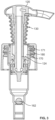
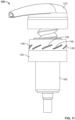
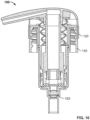
- pump dispenser 100 includes an actuator portion 120 having a dispensing port or outlet nozzle 121, a closure portion 140, and pump body portion 160 including an inlet 161 that is governed by valve 162.
- Closure portion 140 is formed so as to be attachable to a container (not shown), preferably by way of a screw-type or other fitting engagement as is known in this field.
- Inlet 161 and outlet 121 define a flow path for liquids or other flowable materials to be dispensed by pump 100.
- the liquids or flowable materials are confined within a container and drawn through the pump 100 by way of suction created by the reciprocating action of the actuator 120 and selected components of the pump body 140.
- the closure portion 140 is preferably sized so as to be easily adapted and attached to any number of standard container necks.
- Actuator 120 includes a shroud piece 123 that may engage the closure 140 in some embodiments, although in the operating position actuator 120 moves freely up and down relative to closure 140.
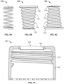
- Biasing member 130 such as an all-plastic bellows spring, is fitted to an interior facing/underside of the shroud 123.
- a duct or tube 124 is coaxially contained with the biasing member 130.
- the outer top facing of the tube 124 and the inner portions of the shroud 123 which serve to further define the flow path and/or outlet 121 may be formed with cooperating features (e.g., bead and groove, snap fittings, screw thread, stopping/positioning flange, etc.) to ensure these elements remain coupled together.
- Shroud 123 may also encase similar cooperating engagement features to attach to the top end of the biasing member 130.
- biasing member 130 To the extent that the weight of the actuator 120 can be minimized, the construction of the biasing member 130 can be adjusted accordingly, although it will be apparent that the biasing force exerted by member 130 must be sufficient to raise the actuator 120 upward. Biasing member must also possess sufficient shape memory and resilience to withstand repeated use. Olefinic materials, including but not limited to polypropylene, polyethylene, and the like, should be particularly useful for forming the biasing member 130, especially in view of the all-plastic aims of this invention.
- Biasing member 130 is generally cylindrical in shape, although it may be imparted with a tapered and/or conical shape. When present, the narrowing portion of the taper may be oriented downward proximate to the body 140/closure 140, although it is possible to position this narrowed end upward to attach to the actuator 120.
- a spiraled or helical bellows 131 imparts an accordion-like construction to facilitate compression and resilient restoration of the biasing member 130 to its extended shape. Alternatively, a series of flexing, indents and extensions could be used to create the same accordion-like structure.
- a more conventional metal or plastic spring, formed as a coil, could be substituted.
- Top and bottom flanges 132, 133 may include engagement features to secure and seal the biasing member 130 within the adjacent components of pump 100 (e.g., actuator 120, body 160, etc.).
- Closure 140 includes a cylindrical cap 141.
- the upper portion of the cap may include features to engage the actuator 120, while the lower portion has a cup-like shape defined by annular skirt 142. Threads 143 are formed on an inner facing of the skirt 142 to engage the container neck.
- An annular panel 144 extends radially inward to define an aperture 145 for receiving and accommodating the biasing member 130 and tube 124.
- a sealing flange 146 may extend into the aperture 145 from the inner-facing edge of panel 144.
- Flange 146 may be angled or otherwise constructed to ensure a sufficient seal is formed when the pump 100 is in a stocked position, particularly with respect to preventing fluid ingress into the inner recesses of the pump 100.
- panel 144 may be formed with one or more raised or lowered portions 147 (relative to the horizontal axis) so as to engage and accommodate connection to the pump body portion 160.
- Body portion 160 includes a piston housing 163 and a sliding piston 164 fitted within the lower portion of the housing 163 to define a variable volume pump chamber 165.
- the piston 164 is urged upward and downward through the chamber 165, with upward motion creating suction that temporarily displaces/opens valve 162 to draw fluid through the inlet 161 and into the chamber.
- piston 164 moves downward while allowing fluid to flow around it and into tube 124.
- fluid in the tube 124 will eventually be expelled through outlet 121.
- a sliding insert 170 is confined within an insert housing 180.
- housing 180 is fitted within the housing 163, which may include an annular ridge, ledge, or flange to secure the housing 180 therein.
- insert 170 is coaxially received within the housing 180.
- the insert 170 will rotate and move upward or downward, depending upon the rotation of actuator 120. More specifically, owing to the fixed connection between the biasing member 130 and formations 174 spaced regularly or irregularly on top of the insert 170 (but in a manner that cooperates with corresponding features on the flange 132 or 133), these items will move in concert when the actuator shroud 123 is rotated.
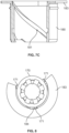
- One or more projections 171 formed along an outer facing of the insert 170 then move through guides 181, provided as channels, grooves, or ledge-like formations positioned along the inner facing of housing 180.
- guides 181 have a helical shape so as to allow smooth rotation and movement of the actuator 120.
- guides 181 could have a straight vertical orientation or even a stepped or other variable pattern.
- the same number of projections 171 and guides 181 are provided. When two or more projections 171 are present, they should be spaced apart, preferably at even and equal intervals, to ensure smooth movement and rotation.
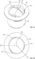
- Insert 170 will have a hollow tubular construction, preferably with a circular cylindrical shape.
- One or more flanges may be formed in arced sections along the top of the insert 170 to serve as the projections 171.
- ribs 172 can be provided to help position and guide the tube 124, which will slide freely through this central aperture 173.
- a groove, channel or other attachment feature will selectively receive and engage the piston 164.
- the lower end of tube 124 has a pair of vertical spaced apart ridges or engagement features, also to urge the piston 164 into proper position within chamber 165.
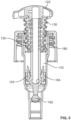
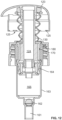
- Insert 170 is of sufficient diameter to extend almost completely below the insert housing 180 when the pump is in the stocked position.
- projections 171 engage the ledge on the housing 163 that serves to restrain the insert housing 180.
- the biasing member 130 is mostly or completely received within the inner volume normally occupied by the body portion 160. The spacing and size is such that biasing member 130 will not be substantially compressed in this stocked position.
- the tube 124 and piston 164 are configured at sufficient axial heights to ensure all components will be accommodated within the housing 163 and, more specifically in some instances, the chamber 165.
- the sliding insert 170 remains fixed in an up position, at or nearly flush with panel 144.
- the actuator 120 is depressed, the biasing member 130 is compressed while the tube 124 and associated, moveable components in the body portion 160 move downward. Upon release of the actuator 120, biasing member 130 urges these components upward and, in that process creates suction within the chamber 165.
- Insert housing 180 is also a hollow tube having an identical circular cylindrical shape on its inner aperture/bore 182.
- the inner diameter of insert housing 180 accommodates the outer diameter of sliding insert 170 and, in the stocked position, most or all of the biasing member 130.
- guides 181 are formed on the inner facings of the aperture/bore 182.
- stoppers 184 may be provided at the top and/or bottom edges of guide 181. Stoppers 184 are substantially horizontal ledges on which the projections may rest.
- Ramped sections 185 may be interposed between the main, vertical channel defined by guide 181 and the stopper ledge 184, so as to help keep the projections 171 seated on the stopper 184. Ramps 185 will be formed to require a certain level of torque is needed to move the pump 100 from operating to stocked positions (or vice versa).
- the outer shape (and diameter) of the insert housing 180 does not necessarily need to retain the circular cylindrical shape of the insert 170. Instead, the outer facing of housing 180 only needs to fit in and cooperate with the piston housing 163.
- An annular flange 183 is formed at the top of housing 180. This flange 183 helps attach and seal the body portion 160 to the closure 140. While only completely up and completely down positions are shown for the insert 170 and housing 180 combination, additional stoppers 184 and/or ramps 185 could be formed at a midway position.
- additional locking features can also be formed on the exterior facing of the closure 140 and the inner recess defined by the shroud 123.
- one or more radially inward indents or formations 125 are provided on the inner facing of the shroud 123.
- one or a series of spaced apart projections 148 are formed on an outer facing of the closure cap 141, possibly in the skirt 142 and/or at an upper portion.
- the indents 125 pass between the spaces between the projections 148.
- the projections 148 may be similar to guides, having a sloping or slanted surface to facilitate the rotation of the actuator 123.
- the indents 125 catch on a portion of the projections 148 so as to capture and retain the actuator 120 in a down-locked position.
- the indents 125/projections 148 may form a fully down-locked position or they may simply provide a partial down lock. In either case, the indents 125/projections 148 provide an additional safeguard against unwanted release of the actuator 120.
- the indents 125/projections 148 can be placed in radial positions around the periphery to facilitate the twisting motion imparted by the helical guides 181 and/or to terminate so as to coincide with a resting position of projections 171 on stoppers 184. In this manner, these further embodiments support the operational and stocked positions that help preserve and protect the biasing member.
- the pump bellows/biasing member 130 serves as a replacement for metal biasing springs.
- the bellows By affixing the bellows to a carrier element and allowing that carrier element to toggle between up and down locked positioned by engaging radial projections into corresponding beads, grooves, or aperture-like structures on an inner facing of the pump body, the bellows can be concealed within the container neck and the pump chamber without compression. When released, the projections slide freely along that inner surface so as to allow normal actuation and reciprocation of the pump.
- metal springs may not be desirable in certain context, metal springs can nevertheless be incorporated in certain aspects and embodiments of this invention.
- all components should be made of materials having sufficient flexibility and structural integrity, as well as a chemically inert nature.
- the materials should also be selected for workability, cost, and weight.
- Common polymers amenable to injection molding, extrusion, blow molding, or other common forming processes should have particular utility.
- references to coupling in this disclosure are to be understood as encompassing any of the conventional means used in this field. This may take the form of snap- or force fitting of components, although threaded connections, bead- and-groove, and slot-and-flange assemblies could be employed. Adhesive and fasteners could also be used, although such components must be judiciously selected so as to retain the recyclable nature of the assembly.
- engagement may involve coupling or an abutting relationship.
Landscapes
- Engineering & Computer Science (AREA)
- Mechanical Engineering (AREA)
- General Engineering & Computer Science (AREA)
- Reciprocating Pumps (AREA)
- Containers And Packaging Bodies Having A Special Means To Remove Contents (AREA)
Claims (13)
- Spenderpumpe (100), die in der Lage ist, in Betriebs- und Lagerungspositionen ohne unerwünschte Kompression von Komponenten verriegelt zu werden, wobei die Pumpe Folgendes umfasst:einen Aktuator (120), der einen Fluidströmungsweg (124) mit einem Auslass (121) definiert und an einem oberen Ende eines Vorspannelements (130) befestigt ist; undeinen Verschlusskörper (140) mit einer zylindrischen Schürze (142) und einer zentralen Öffnung (145), die eine Hin- und Herbewegung des Aktuators (120) durch sie hindurch ermöglicht,dadurch gekennzeichnet, dass die Spenderpumpe ferner einen Pumpenkörper (160) mit einem Außengehäuse (163) umfasst, das an dem Verschlusskörper (140) befestigt ist, wobei das Außengehäuse (163) koaxial Teile des Aktuators (120) innerhalb einer Pumpenkammer (165) aufnimmt, die innerhalb des Außengehäuses (163) ausgebildet ist, und mit einem verschiebbaren Einsatz (170), der verschiebbar in einem Einsatzgehäuse (180) aufgenommen ist, wobei das Einsatzgehäuse (180) an dem Außengehäuse (163) befestigt ist und wobei Führungen (181) und Anschlagelemente (184), die an einer Innenseite des Einsatzgehäuses (180) ausgebildet sind, mit Vorsprüngen (171) zusammenwirken, die sich von einer Außenseite des Einsatzes (170) radial nach außen erstrecken, um es dem Aktuator (120) zu ermöglichen, in einer Betriebsposition selektiv nach oben verriegelt und in einer Lagerungsposition nach unten verriegelt zu werden, ohne dass das Vorspannelement (130) wesentliche Kompression erfährt.
- Pumpe (100) nach Anspruch 1, wobei Rampen (185) zwischen den Führungen (181) und Anschlagelementen (185) angeordnet sind.
- Pumpe (100) nach Anspruch 1, wobei das Vorspannelement (130) einen Balg umfasst.
- Pumpe (100) nach Anspruch 3, wobei der Balg eine verjüngte oder konische Form aufweist.
- Pumpe (100) nach Anspruch 3, wobei der Balg Flansche (132, 133) aufweist, die separat an dem Aktuator (120) und dem Einsatz (170) befestigt sind.
- Pumpe (100) nach Anspruch 1, wobei der verschiebbare Einsatz (170) und das Einsatzgehäuse (180) zusammenwirkende, koaxial hohle Rohre bilden.
- Pumpe (100) nach Anspruch 6, wobei die Führungen (184) an einer Innenfläche des Einsatzgehäuses (180) ausgebildet sind.
- Pumpe nach Anspruch 7, wobei an einer Außenfläche des verschiebbaren Einsatzes (170) radial verlaufende Vorsprünge (171) ausgebildet sind.
- Pumpe nach Anspruch 1, wobei die Führungen (184) auf einer Innenfläche des Einsatzgehäuses (180) einem schraubenförmigen Weg folgen.
- Pumpe (100) nach Anspruch 1, wobei das Einsatzgehäuse (180) koaxial in das Außengehäuse (163) eingepasst ist, so dass es auf einer ringförmigen Schulter aufliegt, die an einer Innenfläche des Außengehäuses (163) unmittelbar über der Pumpenkammer (165) ausgebildet ist.
- Pumpe (100) nach Anspruch 1, wobei ein Dichtungsflansch (146) an dem Verschlusskörper (140) in der Nähe der zentralen Öffnung (145) ausgebildet ist.
- Pumpe (100) nach Anspruch 1, wobei an der Innenfläche des Aktuators (120) Einbuchtungen (125) vorgesehen sind, wobei die Einbuchtungen mit äußeren Vorsprüngen (148) zusammenwirken, die an einer Außenfläche des Verschlusskörpers (140) ausgebildet sind, um eine zweite Lagerungsposition zu definieren.
- Pumpe (100) nach Anspruch 1, wobei die äußeren Vorsprünge (148) abgewinkelt sind.
Applications Claiming Priority (2)
| Application Number | Priority Date | Filing Date | Title |
|---|---|---|---|
| IT102019000021321A IT201900021321A1 (it) | 2019-11-15 | 2019-11-15 | Pompa a soffietto bloccabile in posizione ritratta |
| PCT/EP2020/082302 WO2021094621A1 (en) | 2019-11-15 | 2020-11-16 | Down-lock bellows pump |
Publications (2)
| Publication Number | Publication Date |
|---|---|
| EP4058209A1 EP4058209A1 (de) | 2022-09-21 |
| EP4058209B1 true EP4058209B1 (de) | 2024-04-24 |
Family
ID=69743880
Family Applications (1)
| Application Number | Title | Priority Date | Filing Date |
|---|---|---|---|
| EP20804294.5A Active EP4058209B1 (de) | 2019-11-15 | 2020-11-16 | Faltenbalgpumpe mit abwärtssperre |
Country Status (5)
| Country | Link |
|---|---|
| US (1) | US12151253B2 (de) |
| EP (1) | EP4058209B1 (de) |
| CN (1) | CN114981015B (de) |
| IT (1) | IT201900021321A1 (de) |
| WO (1) | WO2021094621A1 (de) |
Families Citing this family (8)
| Publication number | Priority date | Publication date | Assignee | Title |
|---|---|---|---|---|
| WO2021206252A1 (ko) * | 2020-04-07 | 2021-10-14 | 주식회사 삼화 | 펌프캡 |
| CN115697569A (zh) * | 2020-05-29 | 2023-02-03 | Rpc布兰姆拉格股份有限公司 | 用于分配流体的泵 |
| FR3129612B1 (fr) * | 2021-11-29 | 2024-07-12 | Silgan Dispensing Systems Le Treport | Tete de distribution d’un produit fluide et flacon de produit fluide associe |
| CN116923889A (zh) * | 2022-04-08 | 2023-10-24 | 天舟医疗(苏州)有限公司 | 泵送装置 |
| WO2025153171A1 (de) * | 2024-01-16 | 2025-07-24 | ADA Cosmetics International GmbH | Pumpvorrichtung für einen dosierspender |
| KR102946286B1 (ko) * | 2024-03-26 | 2026-03-31 | 주식회사 삼화 | 부유 캡슐을 함유하는 내용물을 토출하기 위한 토출펌프, 이에 사용되는 튜브형 스프링 및 이들을 구비한 토출용기 |
| FR3164402A1 (fr) * | 2024-07-10 | 2026-01-16 | Aptar France Sas | Dispositif de distribution de produit fluide |
| CN120885355A (zh) * | 2024-08-02 | 2025-11-04 | 阿普塔(中国)投资有限公司 | 一种可清洗流体产品分配器 |
Family Cites Families (22)
| Publication number | Priority date | Publication date | Assignee | Title |
|---|---|---|---|---|
| US3362343A (en) * | 1966-03-01 | 1968-01-09 | Clamar Inc | Liquid dispenser |
| GB9117717D0 (en) * | 1991-08-16 | 1991-10-02 | English Glass Co Ltd | Dispenser pumps |
| US5899363A (en) * | 1997-12-22 | 1999-05-04 | Owens-Illinois Closure Inc. | Pump dispenser having a locking system with detents |
| US6006949A (en) * | 1998-01-12 | 1999-12-28 | Continental Sprayers International, Inc. | Manually operated reciprocating liquid pump with sealing vent opening |
| IT1315312B1 (it) | 2000-04-13 | 2003-02-10 | Taplast Spa | Pompa erogatrice multidose |
| EP1266696A1 (de) | 2001-06-13 | 2002-12-18 | Taplast S.p.A. | Balgpumpe zur Abgabe von Gasflüssigkeitmischungen |
| US6698623B2 (en) * | 2002-04-17 | 2004-03-02 | Valois S.A. | Fluid dispenser pump |
| ITVI20040169A1 (it) | 2004-07-09 | 2004-10-09 | Taplast Spa | Unita' per l'erogazione di fluidi o miscele e relativo dispositivo di erogazione |
| US7735692B2 (en) * | 2006-10-10 | 2010-06-15 | Meadwestvaco Calmar, Inc. | Rotating dispenser head with locking and venting closure connector for an air foaming pump dispenser |
| US7654409B2 (en) | 2008-02-19 | 2010-02-02 | Hoffmann Roy W | Shopping bag storage and dispensing unit |
| FR2941933B1 (fr) * | 2009-02-06 | 2016-02-12 | Rexam Pharma La Verpilliere | Dispositif pour la delivrance d'un produit comportant une pompe, comprenant une partie fixe et une partie mobile. |
| IT1393228B1 (it) * | 2009-03-02 | 2012-04-11 | Taplast Srl | Unita' per l'erogazione di fluidi o miscele e relativo dispositivo di erogazione. |
| GB0920768D0 (en) * | 2009-11-26 | 2010-01-13 | Rieke Corp | Dispenser pumps |
| WO2011064584A1 (en) * | 2009-11-26 | 2011-06-03 | Leafgreen Limited | Manual pump dispenser and a method of manufacturing the same |
| CN103420022B (zh) * | 2012-05-16 | 2015-09-09 | 丁要武 | 按压式液体泵 |
| GB2530613A (en) * | 2014-07-14 | 2016-03-30 | Rieke Packaging Systems Ltd | Pump dispensers |
| GB2531997B (en) | 2014-10-20 | 2018-08-01 | Rieke Packaging Systems Ltd | Pump dispenser with deformable pump chamber wall |
| GB201601237D0 (en) | 2016-01-22 | 2016-03-09 | Rieke Packaging Systems Ltd | Dispensing closures and dispensers |
| CA2908770C (en) * | 2015-10-15 | 2023-04-11 | Heiner Ophardt | Cover arrangement for fluid dispenser |
| GB201518910D0 (en) | 2015-10-26 | 2015-12-09 | Rieke Packaging Systems Ltd | Dispensers |
| GB201520997D0 (en) * | 2015-11-27 | 2016-01-13 | Rieke Packaging Systems Ltd | Dispensers |
| US10493478B2 (en) * | 2017-07-14 | 2019-12-03 | Armin Arminak | Hand pump with folding nozzle |
-
2019
- 2019-11-15 IT IT102019000021321A patent/IT201900021321A1/it unknown
-
2020
- 2020-11-16 CN CN202080093453.7A patent/CN114981015B/zh active Active
- 2020-11-16 US US17/775,702 patent/US12151253B2/en active Active
- 2020-11-16 WO PCT/EP2020/082302 patent/WO2021094621A1/en not_active Ceased
- 2020-11-16 EP EP20804294.5A patent/EP4058209B1/de active Active
Also Published As
| Publication number | Publication date |
|---|---|
| EP4058209A1 (de) | 2022-09-21 |
| WO2021094621A1 (en) | 2021-05-20 |
| IT201900021321A1 (it) | 2021-05-15 |
| CN114981015B (zh) | 2024-12-27 |
| CN114981015A (zh) | 2022-08-30 |
| US20230034207A1 (en) | 2023-02-02 |
| US12151253B2 (en) | 2024-11-26 |
Similar Documents
| Publication | Publication Date | Title |
|---|---|---|
| US12151253B2 (en) | Down-lock bellows pump | |
| US12364995B2 (en) | All-polymer helical biasing member and pump dispenser incorporating same | |
| US11446692B2 (en) | Pump dispensers | |
| US11413638B2 (en) | Dispenser pumps and dispensers | |
| US20250041888A1 (en) | Single-polymer dispenser for viscous fluids and oils | |
| US20250018411A1 (en) | Single-polymer, reciprocating dispenser for foam products | |
| CN114450093B (zh) | 聚合物泵分配器 | |
| US20250010320A1 (en) | Integral locking mechanism for reciprocating pumps | |
| WO2023012238A1 (en) | Single polymer, dome-actuated pump | |
| US11850613B2 (en) | All-polymer pump dispenser with internal plug seal | |
| WO2026050365A1 (en) | Integrated and removable pump dispenser with camming collet and collar | |
| EP4651996A1 (de) | Halter und einlassventil für kolbenpumpen |
Legal Events
| Date | Code | Title | Description |
|---|---|---|---|
| STAA | Information on the status of an ep patent application or granted ep patent |
Free format text: STATUS: UNKNOWN |
|
| STAA | Information on the status of an ep patent application or granted ep patent |
Free format text: STATUS: THE INTERNATIONAL PUBLICATION HAS BEEN MADE |
|
| PUAI | Public reference made under article 153(3) epc to a published international application that has entered the european phase |
Free format text: ORIGINAL CODE: 0009012 |
|
| STAA | Information on the status of an ep patent application or granted ep patent |
Free format text: STATUS: REQUEST FOR EXAMINATION WAS MADE |
|
| 17P | Request for examination filed |
Effective date: 20220606 |
|
| AK | Designated contracting states |
Kind code of ref document: A1 Designated state(s): AL AT BE BG CH CY CZ DE DK EE ES FI FR GB GR HR HU IE IS IT LI LT LU LV MC MK MT NL NO PL PT RO RS SE SI SK SM TR |
|
| DAV | Request for validation of the european patent (deleted) | ||
| DAX | Request for extension of the european patent (deleted) | ||
| GRAP | Despatch of communication of intention to grant a patent |
Free format text: ORIGINAL CODE: EPIDOSNIGR1 |
|
| STAA | Information on the status of an ep patent application or granted ep patent |
Free format text: STATUS: GRANT OF PATENT IS INTENDED |
|
| INTG | Intention to grant announced |
Effective date: 20231123 |
|
| GRAS | Grant fee paid |
Free format text: ORIGINAL CODE: EPIDOSNIGR3 |
|
| GRAA | (expected) grant |
Free format text: ORIGINAL CODE: 0009210 |
|
| STAA | Information on the status of an ep patent application or granted ep patent |
Free format text: STATUS: THE PATENT HAS BEEN GRANTED |
|
| P01 | Opt-out of the competence of the unified patent court (upc) registered |
Effective date: 20240227 |
|
| AK | Designated contracting states |
Kind code of ref document: B1 Designated state(s): AL AT BE BG CH CY CZ DE DK EE ES FI FR GB GR HR HU IE IS IT LI LT LU LV MC MK MT NL NO PL PT RO RS SE SI SK SM TR |
|
| REG | Reference to a national code |
Ref country code: GB Ref legal event code: FG4D |
|
| REG | Reference to a national code |
Ref country code: CH Ref legal event code: EP |
|
| REG | Reference to a national code |
Ref country code: DE Ref legal event code: R096 Ref document number: 602020029732 Country of ref document: DE |
|
| REG | Reference to a national code |
Ref country code: IE Ref legal event code: FG4D |
|
| REG | Reference to a national code |
Ref country code: LT Ref legal event code: MG9D |
|
| REG | Reference to a national code |
Ref country code: NL Ref legal event code: MP Effective date: 20240424 |
|
| REG | Reference to a national code |
Ref country code: AT Ref legal event code: MK05 Ref document number: 1679032 Country of ref document: AT Kind code of ref document: T Effective date: 20240424 |
|
| PG25 | Lapsed in a contracting state [announced via postgrant information from national office to epo] |
Ref country code: NL Free format text: LAPSE BECAUSE OF FAILURE TO SUBMIT A TRANSLATION OF THE DESCRIPTION OR TO PAY THE FEE WITHIN THE PRESCRIBED TIME-LIMIT Effective date: 20240424 |
|
| PG25 | Lapsed in a contracting state [announced via postgrant information from national office to epo] |
Ref country code: NL Free format text: LAPSE BECAUSE OF FAILURE TO SUBMIT A TRANSLATION OF THE DESCRIPTION OR TO PAY THE FEE WITHIN THE PRESCRIBED TIME-LIMIT Effective date: 20240424 |
|
| PG25 | Lapsed in a contracting state [announced via postgrant information from national office to epo] |
Ref country code: IS Free format text: LAPSE BECAUSE OF FAILURE TO SUBMIT A TRANSLATION OF THE DESCRIPTION OR TO PAY THE FEE WITHIN THE PRESCRIBED TIME-LIMIT Effective date: 20240824 |
|
| PG25 | Lapsed in a contracting state [announced via postgrant information from national office to epo] |
Ref country code: BG Free format text: LAPSE BECAUSE OF FAILURE TO SUBMIT A TRANSLATION OF THE DESCRIPTION OR TO PAY THE FEE WITHIN THE PRESCRIBED TIME-LIMIT Effective date: 20240424 |
|
| PG25 | Lapsed in a contracting state [announced via postgrant information from national office to epo] |
Ref country code: HR Free format text: LAPSE BECAUSE OF FAILURE TO SUBMIT A TRANSLATION OF THE DESCRIPTION OR TO PAY THE FEE WITHIN THE PRESCRIBED TIME-LIMIT Effective date: 20240424 Ref country code: FI Free format text: LAPSE BECAUSE OF FAILURE TO SUBMIT A TRANSLATION OF THE DESCRIPTION OR TO PAY THE FEE WITHIN THE PRESCRIBED TIME-LIMIT Effective date: 20240424 |
|
| PG25 | Lapsed in a contracting state [announced via postgrant information from national office to epo] |
Ref country code: GR Free format text: LAPSE BECAUSE OF FAILURE TO SUBMIT A TRANSLATION OF THE DESCRIPTION OR TO PAY THE FEE WITHIN THE PRESCRIBED TIME-LIMIT Effective date: 20240725 |
|
| PG25 | Lapsed in a contracting state [announced via postgrant information from national office to epo] |
Ref country code: PT Free format text: LAPSE BECAUSE OF FAILURE TO SUBMIT A TRANSLATION OF THE DESCRIPTION OR TO PAY THE FEE WITHIN THE PRESCRIBED TIME-LIMIT Effective date: 20240826 |
|
| PG25 | Lapsed in a contracting state [announced via postgrant information from national office to epo] |
Ref country code: ES Free format text: LAPSE BECAUSE OF FAILURE TO SUBMIT A TRANSLATION OF THE DESCRIPTION OR TO PAY THE FEE WITHIN THE PRESCRIBED TIME-LIMIT Effective date: 20240424 |
|
| PG25 | Lapsed in a contracting state [announced via postgrant information from national office to epo] |
Ref country code: AT Free format text: LAPSE BECAUSE OF FAILURE TO SUBMIT A TRANSLATION OF THE DESCRIPTION OR TO PAY THE FEE WITHIN THE PRESCRIBED TIME-LIMIT Effective date: 20240424 |
|
| PG25 | Lapsed in a contracting state [announced via postgrant information from national office to epo] |
Ref country code: PL Free format text: LAPSE BECAUSE OF FAILURE TO SUBMIT A TRANSLATION OF THE DESCRIPTION OR TO PAY THE FEE WITHIN THE PRESCRIBED TIME-LIMIT Effective date: 20240424 |
|
| PG25 | Lapsed in a contracting state [announced via postgrant information from national office to epo] |
Ref country code: LV Free format text: LAPSE BECAUSE OF FAILURE TO SUBMIT A TRANSLATION OF THE DESCRIPTION OR TO PAY THE FEE WITHIN THE PRESCRIBED TIME-LIMIT Effective date: 20240424 |
|
| PG25 | Lapsed in a contracting state [announced via postgrant information from national office to epo] |
Ref country code: PT Free format text: LAPSE BECAUSE OF FAILURE TO SUBMIT A TRANSLATION OF THE DESCRIPTION OR TO PAY THE FEE WITHIN THE PRESCRIBED TIME-LIMIT Effective date: 20240826 Ref country code: PL Free format text: LAPSE BECAUSE OF FAILURE TO SUBMIT A TRANSLATION OF THE DESCRIPTION OR TO PAY THE FEE WITHIN THE PRESCRIBED TIME-LIMIT Effective date: 20240424 Ref country code: NO Free format text: LAPSE BECAUSE OF FAILURE TO SUBMIT A TRANSLATION OF THE DESCRIPTION OR TO PAY THE FEE WITHIN THE PRESCRIBED TIME-LIMIT Effective date: 20240724 Ref country code: LV Free format text: LAPSE BECAUSE OF FAILURE TO SUBMIT A TRANSLATION OF THE DESCRIPTION OR TO PAY THE FEE WITHIN THE PRESCRIBED TIME-LIMIT Effective date: 20240424 Ref country code: IS Free format text: LAPSE BECAUSE OF FAILURE TO SUBMIT A TRANSLATION OF THE DESCRIPTION OR TO PAY THE FEE WITHIN THE PRESCRIBED TIME-LIMIT Effective date: 20240824 Ref country code: HR Free format text: LAPSE BECAUSE OF FAILURE TO SUBMIT A TRANSLATION OF THE DESCRIPTION OR TO PAY THE FEE WITHIN THE PRESCRIBED TIME-LIMIT Effective date: 20240424 Ref country code: GR Free format text: LAPSE BECAUSE OF FAILURE TO SUBMIT A TRANSLATION OF THE DESCRIPTION OR TO PAY THE FEE WITHIN THE PRESCRIBED TIME-LIMIT Effective date: 20240725 Ref country code: FI Free format text: LAPSE BECAUSE OF FAILURE TO SUBMIT A TRANSLATION OF THE DESCRIPTION OR TO PAY THE FEE WITHIN THE PRESCRIBED TIME-LIMIT Effective date: 20240424 Ref country code: ES Free format text: LAPSE BECAUSE OF FAILURE TO SUBMIT A TRANSLATION OF THE DESCRIPTION OR TO PAY THE FEE WITHIN THE PRESCRIBED TIME-LIMIT Effective date: 20240424 Ref country code: BG Free format text: LAPSE BECAUSE OF FAILURE TO SUBMIT A TRANSLATION OF THE DESCRIPTION OR TO PAY THE FEE WITHIN THE PRESCRIBED TIME-LIMIT Effective date: 20240424 Ref country code: AT Free format text: LAPSE BECAUSE OF FAILURE TO SUBMIT A TRANSLATION OF THE DESCRIPTION OR TO PAY THE FEE WITHIN THE PRESCRIBED TIME-LIMIT Effective date: 20240424 Ref country code: RS Free format text: LAPSE BECAUSE OF FAILURE TO SUBMIT A TRANSLATION OF THE DESCRIPTION OR TO PAY THE FEE WITHIN THE PRESCRIBED TIME-LIMIT Effective date: 20240724 |
|
| PG25 | Lapsed in a contracting state [announced via postgrant information from national office to epo] |
Ref country code: DK Free format text: LAPSE BECAUSE OF FAILURE TO SUBMIT A TRANSLATION OF THE DESCRIPTION OR TO PAY THE FEE WITHIN THE PRESCRIBED TIME-LIMIT Effective date: 20240424 |
|
| PG25 | Lapsed in a contracting state [announced via postgrant information from national office to epo] |
Ref country code: EE Free format text: LAPSE BECAUSE OF FAILURE TO SUBMIT A TRANSLATION OF THE DESCRIPTION OR TO PAY THE FEE WITHIN THE PRESCRIBED TIME-LIMIT Effective date: 20240424 |
|
| PG25 | Lapsed in a contracting state [announced via postgrant information from national office to epo] |
Ref country code: CZ Free format text: LAPSE BECAUSE OF FAILURE TO SUBMIT A TRANSLATION OF THE DESCRIPTION OR TO PAY THE FEE WITHIN THE PRESCRIBED TIME-LIMIT Effective date: 20240424 |
|
| PG25 | Lapsed in a contracting state [announced via postgrant information from national office to epo] |
Ref country code: RO Free format text: LAPSE BECAUSE OF FAILURE TO SUBMIT A TRANSLATION OF THE DESCRIPTION OR TO PAY THE FEE WITHIN THE PRESCRIBED TIME-LIMIT Effective date: 20240424 Ref country code: SK Free format text: LAPSE BECAUSE OF FAILURE TO SUBMIT A TRANSLATION OF THE DESCRIPTION OR TO PAY THE FEE WITHIN THE PRESCRIBED TIME-LIMIT Effective date: 20240424 |
|
| REG | Reference to a national code |
Ref country code: DE Ref legal event code: R097 Ref document number: 602020029732 Country of ref document: DE |
|
| PG25 | Lapsed in a contracting state [announced via postgrant information from national office to epo] |
Ref country code: SM Free format text: LAPSE BECAUSE OF FAILURE TO SUBMIT A TRANSLATION OF THE DESCRIPTION OR TO PAY THE FEE WITHIN THE PRESCRIBED TIME-LIMIT Effective date: 20240424 |
|
| PG25 | Lapsed in a contracting state [announced via postgrant information from national office to epo] |
Ref country code: SM Free format text: LAPSE BECAUSE OF FAILURE TO SUBMIT A TRANSLATION OF THE DESCRIPTION OR TO PAY THE FEE WITHIN THE PRESCRIBED TIME-LIMIT Effective date: 20240424 Ref country code: SK Free format text: LAPSE BECAUSE OF FAILURE TO SUBMIT A TRANSLATION OF THE DESCRIPTION OR TO PAY THE FEE WITHIN THE PRESCRIBED TIME-LIMIT Effective date: 20240424 Ref country code: RO Free format text: LAPSE BECAUSE OF FAILURE TO SUBMIT A TRANSLATION OF THE DESCRIPTION OR TO PAY THE FEE WITHIN THE PRESCRIBED TIME-LIMIT Effective date: 20240424 Ref country code: EE Free format text: LAPSE BECAUSE OF FAILURE TO SUBMIT A TRANSLATION OF THE DESCRIPTION OR TO PAY THE FEE WITHIN THE PRESCRIBED TIME-LIMIT Effective date: 20240424 Ref country code: DK Free format text: LAPSE BECAUSE OF FAILURE TO SUBMIT A TRANSLATION OF THE DESCRIPTION OR TO PAY THE FEE WITHIN THE PRESCRIBED TIME-LIMIT Effective date: 20240424 Ref country code: CZ Free format text: LAPSE BECAUSE OF FAILURE TO SUBMIT A TRANSLATION OF THE DESCRIPTION OR TO PAY THE FEE WITHIN THE PRESCRIBED TIME-LIMIT Effective date: 20240424 |
|
| PLBE | No opposition filed within time limit |
Free format text: ORIGINAL CODE: 0009261 |
|
| STAA | Information on the status of an ep patent application or granted ep patent |
Free format text: STATUS: NO OPPOSITION FILED WITHIN TIME LIMIT |
|
| 26N | No opposition filed |
Effective date: 20250127 |
|
| PG25 | Lapsed in a contracting state [announced via postgrant information from national office to epo] |
Ref country code: SI Free format text: LAPSE BECAUSE OF FAILURE TO SUBMIT A TRANSLATION OF THE DESCRIPTION OR TO PAY THE FEE WITHIN THE PRESCRIBED TIME-LIMIT Effective date: 20240424 |
|
| REG | Reference to a national code |
Ref country code: CH Ref legal event code: PL |
|
| PG25 | Lapsed in a contracting state [announced via postgrant information from national office to epo] |
Ref country code: MC Free format text: LAPSE BECAUSE OF FAILURE TO SUBMIT A TRANSLATION OF THE DESCRIPTION OR TO PAY THE FEE WITHIN THE PRESCRIBED TIME-LIMIT Effective date: 20240424 |
|
| PG25 | Lapsed in a contracting state [announced via postgrant information from national office to epo] |
Ref country code: LU Free format text: LAPSE BECAUSE OF NON-PAYMENT OF DUE FEES Effective date: 20241116 |
|
| REG | Reference to a national code |
Ref country code: CH Ref legal event code: PL |
|
| PG25 | Lapsed in a contracting state [announced via postgrant information from national office to epo] |
Ref country code: CH Free format text: LAPSE BECAUSE OF NON-PAYMENT OF DUE FEES Effective date: 20241130 |
|
| REG | Reference to a national code |
Ref country code: BE Ref legal event code: MM Effective date: 20241130 |
|
| PG25 | Lapsed in a contracting state [announced via postgrant information from national office to epo] |
Ref country code: SE Free format text: LAPSE BECAUSE OF FAILURE TO SUBMIT A TRANSLATION OF THE DESCRIPTION OR TO PAY THE FEE WITHIN THE PRESCRIBED TIME-LIMIT Effective date: 20240424 |
|
| PG25 | Lapsed in a contracting state [announced via postgrant information from national office to epo] |
Ref country code: BE Free format text: LAPSE BECAUSE OF NON-PAYMENT OF DUE FEES Effective date: 20241130 |
|
| PG25 | Lapsed in a contracting state [announced via postgrant information from national office to epo] |
Ref country code: IE Free format text: LAPSE BECAUSE OF NON-PAYMENT OF DUE FEES Effective date: 20241116 |
|
| PGFP | Annual fee paid to national office [announced via postgrant information from national office to epo] |
Ref country code: DE Payment date: 20251128 Year of fee payment: 6 |
|
| PGFP | Annual fee paid to national office [announced via postgrant information from national office to epo] |
Ref country code: GB Payment date: 20251127 Year of fee payment: 6 |
|
| PGFP | Annual fee paid to national office [announced via postgrant information from national office to epo] |
Ref country code: IT Payment date: 20251119 Year of fee payment: 6 |
|
| PGFP | Annual fee paid to national office [announced via postgrant information from national office to epo] |
Ref country code: FR Payment date: 20251125 Year of fee payment: 6 |
|
| PG25 | Lapsed in a contracting state [announced via postgrant information from national office to epo] |
Ref country code: HU Free format text: LAPSE BECAUSE OF FAILURE TO SUBMIT A TRANSLATION OF THE DESCRIPTION OR TO PAY THE FEE WITHIN THE PRESCRIBED TIME-LIMIT; INVALID AB INITIO Effective date: 20201116 |
|
| PG25 | Lapsed in a contracting state [announced via postgrant information from national office to epo] |
Ref country code: CY Free format text: LAPSE BECAUSE OF FAILURE TO SUBMIT A TRANSLATION OF THE DESCRIPTION OR TO PAY THE FEE WITHIN THE PRESCRIBED TIME-LIMIT; INVALID AB INITIO Effective date: 20201116 |