EP4058749B1 - Objet pyrotechnique - Google Patents
Objet pyrotechnique Download PDFInfo
- Publication number
- EP4058749B1 EP4058749B1 EP21802646.6A EP21802646A EP4058749B1 EP 4058749 B1 EP4058749 B1 EP 4058749B1 EP 21802646 A EP21802646 A EP 21802646A EP 4058749 B1 EP4058749 B1 EP 4058749B1
- Authority
- EP
- European Patent Office
- Prior art keywords
- ignition
- over
- charge
- opening
- effect
- Prior art date
- Legal status (The legal status is an assumption and is not a legal conclusion. Google has not performed a legal analysis and makes no representation as to the accuracy of the status listed.)
- Active
Links
Images

Classifications
-
- F—MECHANICAL ENGINEERING; LIGHTING; HEATING; WEAPONS; BLASTING
- F42—AMMUNITION; BLASTING
- F42C—AMMUNITION FUZES; ARMING OR SAFETY MEANS THEREFOR
- F42C9/00—Time fuzes; Combined time and percussion or pressure-actuated fuzes; Fuzes for timed self-destruction of ammunition
- F42C9/10—Time fuzes; Combined time and percussion or pressure-actuated fuzes; Fuzes for timed self-destruction of ammunition the timing being caused by combustion
-
- F—MECHANICAL ENGINEERING; LIGHTING; HEATING; WEAPONS; BLASTING
- F42—AMMUNITION; BLASTING
- F42B—EXPLOSIVE CHARGES, e.g. FOR BLASTING, FIREWORKS, AMMUNITION
- F42B3/00—Blasting cartridges, i.e. case and explosive
- F42B3/10—Initiators therefor
- F42B3/16—Pyrotechnic delay initiators
-
- F—MECHANICAL ENGINEERING; LIGHTING; HEATING; WEAPONS; BLASTING
- F42—AMMUNITION; BLASTING
- F42B—EXPLOSIVE CHARGES, e.g. FOR BLASTING, FIREWORKS, AMMUNITION
- F42B5/00—Cartridge ammunition, e.g. separately-loaded propellant charges
- F42B5/02—Cartridges, i.e. cases with charge and missile
- F42B5/16—Cartridges, i.e. cases with charge and missile characterised by composition or physical dimensions or form of propellant charge, with or without projectile, or powder
-
- F—MECHANICAL ENGINEERING; LIGHTING; HEATING; WEAPONS; BLASTING
- F42—AMMUNITION; BLASTING
- F42B—EXPLOSIVE CHARGES, e.g. FOR BLASTING, FIREWORKS, AMMUNITION
- F42B12/00—Projectiles, missiles or mines characterised by the warhead, the intended effect, or the material
- F42B12/02—Projectiles, missiles or mines characterised by the warhead, the intended effect, or the material characterised by the warhead or the intended effect
- F42B12/36—Projectiles, missiles or mines characterised by the warhead, the intended effect, or the material characterised by the warhead or the intended effect for dispensing materials; for producing chemical or physical reaction; for signalling ; for transmitting information
Definitions
- the invention relates to a pyrotechnic object, in particular an irritation body, irritation projectile or ammunition, with an ignition device, with a delay chamber extending along a delay section, in which a delay charge is accommodated, and with at least one and preferably several effect chambers in which one effect set to be ignited is accommodated in each case, the delay chamber being cross-connected to a respective effect chamber via a respective ignition opening branching off from the delay chamber and forming an ignition gap, with in the case of several effect chambers the plurality of transfer openings are arranged in the order of the effect sets to be ignited along the ignition path in succession, starting from the delay chamber.
- pyrotechnic objects are widely known. This can involve irritation bodies, in particular irritation projectiles with a combined flash/bang effect, possibly with fogging, but also ammunition in the broadest sense.
- a delay set is provided along a delay line.
- the delay charge which in particular can include one to three delay charges, in particular an ignition charge, a mixed charge and a main charge, has the task of igniting the first effect charge after a defined time of, for example, 1.5 seconds.
- the delay set is typically arranged axially centrally in the delay chamber forming the delay section and is in particular pressed in.
- a pyrotechnic object in the form of an irritation body with the features of the preamble of claim 1 is previously known from DE 10 2004 059 991 A1 .
- a non-generic pyrotechnic article called a delay element with a gas charge containing an ignition piece with a primer cap and a single continuous channel in a longitudinal direction, which has an ignition channel section, a section for an ignition charge, a section for a delay charge, a section for a transfer charge and a Includes section for a propellant charge to be finally ignited.
- a check valve with a cone and a ball is provided between the ignition channel section and the section for the ignition charge. The ball is embedded in the ignition charge, whose slag supports the seal.
- DE 10 2016 015 042 B4 relates to a non-generic ammunition module with an explosive arrangement in a warhead and a fuse and an ignition channel partially surrounded by the explosive arrangement with pyrotechnic material for igniting the explosive arrangement.
- an ignition channel that is self-sealing in the detonated state. This is realized by providing one or more sealing elements in or near the ignition channel.
- the sealing element can be a body that is introduced into the ignition channel by the at least partially converted explosive in order to seal it.
- the body or the sealing element can also be designed as a casing or sleeve surrounding the ignition channel, see above that it is compressed by the partially reacted explosive and, together with residual pyrotechnic material, causes a sealing of the ignition channel.
- the firing behavior i.e. the kinetics of the progression of the combustion front, and the kinetics of the heat passing through the ignition opening are also important for the proper ignition of the respective effect set of a pyrotechnic object of the type mentioned above and through the respective branching over ignition opening Particles, responsible or mission critical.
- the firing behavior is influenced, among other things, by the pressure conditions and the particle properties of the delay charge. (The same applies to the pressure and the particle arrangement within the respective effect set.)
- the object of the present invention is to address this problem, ie the functional reliability of the proper ignition in question pyrotechnic objects in the broadest sense, including ammunition.
- this object is achieved according to the invention in that an overignition charge that is different and chemically different from the respective effect charge is introduced into the overignition opening or in the several overignition openings in order to at least partially close the overignition opening after it has burned off and through its combustion residue close and thereby reduce or dampen the propagation of a pressure surge that occurs as a result of the ignition of the effect charge in the respective effect chamber and acts on the delay chamber via the respective transfer opening.
- the delay charge goes out, or the compressed delay charge hits one or more of the subsequent transfer openings and thus their associated effect charges, which means uncontrolled multiple ignition of effect charges.
- the burning delay charge will quickly burn past the downstream ignition opening and effect chamber as a result of the pressure surge, without igniting the effect charge. This then remains in the pyrotechnical object as a potentially dangerous explosive charge because it has not been ignited.
- the surface geometry of the combustion front of the delay charge can also be changed by the pressure impact in such a way that oblique combustion occurs, which can also impair proper ignition of the effect charges.
- the present invention it is proposed to deliberately introduce an overignition charge that is different from the effect charge into a respective overignition opening, at least along part of the overignition path formed thereby.
- this reduces the risk of non-ignition because the combustion front is guided to a certain extent can safely propagate through the overignition charge through a respective outgoing overignition opening.
- another important aspect is that the combustion residue remaining immediately after the ignition charge has burned off is able to at least partially close the ignition opening, with the result that the subsequent pressure shock caused by ignition of the effect charge is reduced in its effect on the delay chamber and the delay charge located therein.
- the burning of the overigniting charge is accompanied by the greatest possible formation of slag and overignition capacity, since this forms filling material for filling and sealing the overignition opening.
- the material of the overfiring charge can, for example, be based on a delay and ignition charge material DE 10 2015 014 821 A1 be educated; the relevant content of this publication, ie the composition of the ignition or delay charge material, is included in the content of the present application by reference to this publication.
- the ignition charge is at least 20%, in particular at least 30%, in particular at least 40%, in particular at least 50% and in particular over 100%, in particular at most 90%, in particular at most 80%, in particular, is introduced into the ignition opening over a maximum of 70% of the length of the ignition gap. If, for example, one takes into account the normal extension of the ignition gap formed by the ignition opening of 5-12 mm, then introduction over 30-100% of the length of the ignition gap proves to be preferred.
- the over-igniting charge in the ignition opening is pressed in. This can be done in any manner and, with regard to economic manufacturability, preferably by means of a ram that is introduced radially from the outside.
- the ignition charge is introduced into the ignition opening as a pasty or at least still flowable medium and hardened therein.
- the cross-section change in the ignition opening along the ignition gap is proposed.
- a change in cross section, in particular an expansion or narrowing of the ignition transfer opening allows the ignition charge introduced into the ignition transfer opening to be better anchored in the ignition transfer opening. This applies in particular to the combustion residue of the ignition charge after it has burned off. As a result, the sealing effect or damping effect of the combustion residue of the ignition charge can be further improved.
- a cross-sectional area of the ignition opening changes by at least 10%, in particular by at least 20%, in particular by at least 25%, in particular by at most 60%, in particular by at most 50% along the ignition path, i.e. in the direction of ignition propagation .
- a consequent widening or narrowing can occur along a continuous or discontinuous course, in particular stepped or conical/cone-shaped or also in a rounded shape.
- the change in cross section is oriented in such a way that the ignition propagation opening has an increasing cross-sectional area, ie an expanding cross section.
- the combustion residue can then become wedged in an overignition opening, which in particular tapers conically or funnel-shaped in the direction of propagation of the pressure shock, and close it like a plug.
- the ignition charge is arranged in the area of the change in cross section of the ignition opening viewed in the longitudinal direction of the ignition gap, so that the immobilisation and anchoring of its combustion residue is supported by the change in cross section.
- a housing inner body forming the chambers and an outer, in particular cylindrical, sleeve body surrounding the housing inner body, which forms a grippable outer side of the object and preferably in particular by means of optional sealing elements seals further still open or covered assembly openings communicating with the chambers.
- the interior of the chambers can be effectively protected against environmental influences, in particular penetrating moisture, by means of the sleeve body.
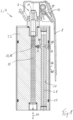
- the pyrotechnic object 2 designed according to the invention shown in the figures for example in the form of an irritation projectile 4 of the BTV "bottom top venting" type (i.e. with the blowing direction up and down or in opposite axial directions), comprises an ignition device 6 of previously known design .
- the ignition device 6 comprises a rocker arm 8 that can be held or pressed and released manually, a removable safety ring (not shown), a spring 10, a striking piece 12 and a percussion cap 14 of a known type, which are therefore not described in detail.
- Axially below the percussion cap 14 extends a delay chamber 16, which is embodied here as a bore, for example, along a delay section 18, in which at least one delay set 20 is arranged.
- the deceleration chamber 16 extends within an exemplary solid housing inner body 22 along an axial longitudinal direction 24, namely centrally in the middle and forms and delimits the deceleration section 18. Radially outside of the deceleration chamber 16 are also in the axial longitudinal direction 24 and are revolver-like and effect chambers 26 arranged concentrically with respect to the delay chamber 16, of which in figure 1 but only one corresponding to the section plane is shown. In each of the effect chambers 26 there is an effect set 28 to be ignited, preferably in the form of a uniformly introduced particle material.
- this application refers to an effect composition or an effect composition material
- this can, for example, be a flash composition and/or a bang composition and/or a smoke composition as an explosive substance.
- a respective effect chamber 26 is connected to the centrally located delay chamber 16 via a respective ignition port 30 .
- the transfer opening 30 is designed here as a bore.
- a combustion front of the deceleration charge 20 is intended to propagate from the ignition device 6 in the axial longitudinal direction 24 along the deceleration path 18 .
- the combustion front reaches the first or a subsequent cross-ignition opening 30, which in this case branches off radially by way of example, it is intended to be cross-ignited through this opening Transfer opening 30 through which the effect charge 28 can be ignited in the associated effect chamber 26 .
- the effect charge 28 can be ignited in the associated effect chamber 26 .
- the combustion front in the delay chamber 16 continues to spread axially until it reaches the next overignition opening 30 in the direction of the delay section 18 and in the same way, as intended, causes the effect charge 28 to be ignited in the associated effect chamber 26 .
- combustion residue 36 within the area 38 of the ignition opening 30 in which the ignition charge 32 is or was arranged.
- the combustion residue 36 therefore preferably comprises a not inconsiderable proportion of slag, which can remain and wedge within the ignition opening 30 .
- This pressure hammer now leads to a compression of the combustion residue 36 within the ignition transfer opening 30 in a manner according to the invention. That is, the combustion residue 36 helps to reduce or dampen the effects and the propagation of the pressure hammer through the ignition transfer opening 30 back towards the delay chamber 16 . As explained in detail at the outset, this proves to be advantageous with regard to improving the reliability of the intended ignitions of the effect sets in sequence.
- the transfer opening 30 has a cross-sectional change 40 along the extent of the transfer gap 34, and the cross-sectional change 40 is preferably oriented such that the transfer opening 30 has an increasing cross-sectional area in the direction of ignition propagation, i.e. in the direction of the effect chamber 26 .
- the cross-sectional change 40 is in the figure 2 conical or funnel-shaped. This shape can be formed, for example, in the form of a stepped bore, in which a radial bore is introduced into the housing inner body 22 from radially outside first with a small diameter drill and then with a larger diameter drill.
- the course of the cross-sectional change 40 can also be machined in the desired manner.
- access occurs from the radial outside through a further radial opening 42 in the inner housing body 22 which is then closed by a blind rivet 44 .
- the inner housing body 22 receives a cylindrical sleeve body 46 radially outside, which forms a manually grippable outer side 48 of the object 2 and, for example, causes a secure sealing of the other radial openings 42 against environmental influences by means of two O-ring seals 50 .
- the pressure surge-reducing or dampening effect of the combustion residue 36 of the ignition charge 32 is particularly effective.
- the combustion residue 36 is partially compressed, as already explained above, so that the particles of the combustion residue 36 wedge against one another in the transfer opening 30 and become an obstacle that is difficult to overcome in terms of pressure.
- the deceleration charge 20 located in the deceleration chamber 16 and its combustion front, which continues to advance as intended, are better protected against the effects of the pressure shock.
- the functional safety and reliability of the ignition of the subsequent effect sets 28 can be significantly improved.
Landscapes
- Engineering & Computer Science (AREA)
- General Engineering & Computer Science (AREA)
- Air Bags (AREA)
Claims (11)
- Objet pyrotechnique (2), en particulier corps irritant, projectile irritant (4) ou munition, avec un dispositif d'allumage (6), avec une chambre de retard (16) qui s'étend le long d'un trajet de retard (18) et à l'intérieur de laquelle est logée une charge de retard (20), et avec au moins une et de préférence plusieurs chambres à effet (26) dans laquelle ou bien dans lesquelles est logée respectivement une charge à effet (28) à allumer, dans lequel la chambre de retard (16) est reliée transversalement à une chambre à effet (26) respective par l'intermédiaire d'une ouverture de surallumage (30) respective qui est dérivée de ladite chambre de retard (16) et qui forme un trajet de surallumage, dans lequel, au cas où il y a une pluralité de chambres à effet (26), les plusieurs ouvertures de surallumage (30) sont agencées de manière à dériver successivement dans l'ordre des charges à effet (28) à allumer, le long du trajet de retard (18), caractérisé par le fait
que dans l'ouverture de surallumage (30) ou dans les plusieurs ouvertures de surallumage (30) est introduite une charge de surallumage (32) qui est différente et chimiquement différente de la charge à effet (28) respective, afin de fermer au moins en partie l'ouverture de surallumage (30) après sa combustion et par ses résidus de combustion (36) et de réduire ou amortir ainsi une propagation d'une surpression qui se produit à la suite de l'allumage de la charge à effet (28) dans la chambre à effet (26) respective et agit sur la chambre de retard (16) via l'ouverture de surallumage (30) respective. - Objet pyrotechnique (2) selon la revendication 1,
caractérisé par le fait que la charge de surallumage (32) est introduite dans ladite ouverture de surallumage (30) sur au moins 20 %, en particulier sur au moins 30 %, en particulier sur au moins 40 %, en particulier sur au moins 50 % et en particulier sur 100 %, en particulier sur 90 % tout au plus, en particulier sur 80 % tout au plus, en particulier sur 70 % tout au plus de la longueur du trajet de surallumage (34). - Objet pyrotechnique (2) selon la revendication 1 ou 2, caractérisé par le fait que la charge de surallumage (32) est pressée dans l'ouverture de surallumage (30).
- Objet pyrotechnique (2) selon la revendication 1, 2 ou 3, caractérisé par le fait que la charge de surallumage (32) est introduite dans l'ouverture de surallumage (30) sous forme de milieu pâteux ou en tout cas encore apte à couler et est durcie dans celle-ci.
- Objet pyrotechnique (2) selon l'une ou plusieurs des revendications précédentes, caractérisé par le fait que l'ouverture de surallumage (30) présente un changement de section transversale (40) le long du trajet de surallumage (34).
- Objet pyrotechnique (2) selon la revendication 5,
caractérisé par le fait qu'une surface de section transversale de l'ouverture de surallumage (30) change le long du trajet de surallumage (34) d'au moins 10 %, en particulier d'au moins 20 %, en particulier d'au moins 25 %, en particulier de 60 % tout au plus, en particulier de 50 % tout au plus. - Objet pyrotechnique (2) selon la revendication 5 ou 6, caractérisé par le fait que le changement de section transversale (40) est orientée de telle sorte que l'ouverture de surallumage (30) présente une surface de section transversale croissante dans le sens de propagation de l'allumage, donc une section transversale qui s'évase.
- Objet pyrotechnique (2) selon la revendication 5, 6 ou 7, caractérisé par le fait que le changement de section transversale (40) est conique ou en forme d'entonnoir.
- Objet pyrotechnique (2) selon l'une ou plusieurs des revendications précédentes 5 à 8, caractérisé par le fait que l'ouverture de surallumage (30) est conçue en tant qu'ouverture étagée, en particulier en tant que trou étagé.
- Objet pyrotechnique (2) selon l'une ou plusieurs des revendications précédentes 5 à 9, caractérisé par le fait que la charge de surallumage (32) est disposée au niveau du changement de section transversale (40) de sorte que l'immobilisation et l'ancrage de son résidu de combustion (36) est supporté par le changement de section transversale (40).
- Objet pyrotechnique (2) selon l'une ou plusieurs des revendications précédentes, caractérisé par le fait qu'il y a un corps intérieur de boîtier (22) formant les chambres (16, 26) ainsi qu'un corps extérieur de douille (46) en particulier cylindrique qui entoure le corps intérieur de boîtier (22) et qui forme une face extérieure (48) de l'objet (2) apte à être embrassée, et qui, de préférence en particulier au moyen d'éléments d'étanchéité (50) optionnels, rend étanche d'autres ouvertures de montage (42) qui sont encore ouvertes ou couvertes et communiquent avec les chambres (16, 26).
Applications Claiming Priority (2)
| Application Number | Priority Date | Filing Date | Title |
|---|---|---|---|
| DE102020129200.7A DE102020129200A1 (de) | 2020-11-05 | 2020-11-05 | Pyrotechnischer Gegenstand |
| PCT/EP2021/080098 WO2022096385A1 (fr) | 2020-11-05 | 2021-10-29 | Objet pyrotechnique |
Publications (2)
| Publication Number | Publication Date |
|---|---|
| EP4058749A1 EP4058749A1 (fr) | 2022-09-21 |
| EP4058749B1 true EP4058749B1 (fr) | 2023-05-10 |
Family
ID=78528925
Family Applications (1)
| Application Number | Title | Priority Date | Filing Date |
|---|---|---|---|
| EP21802646.6A Active EP4058749B1 (fr) | 2020-11-05 | 2021-10-29 | Objet pyrotechnique |
Country Status (4)
| Country | Link |
|---|---|
| US (1) | US12196536B2 (fr) |
| EP (1) | EP4058749B1 (fr) |
| DE (1) | DE102020129200A1 (fr) |
| WO (1) | WO2022096385A1 (fr) |
Family Cites Families (14)
| Publication number | Priority date | Publication date | Assignee | Title |
|---|---|---|---|---|
| BE624024A (fr) * | 1961-10-24 | |||
| DE2842797C2 (de) * | 1978-09-30 | 1986-01-23 | Nico-Pyrotechnik Hans-Jürgen Diederichs KG, 2077 Trittau | Wurfkörper |
| US4791870A (en) * | 1983-04-05 | 1988-12-20 | Haley & Weller Limited | Pyrotechnic assembly |
| DE3813039A1 (de) | 1988-04-19 | 1989-11-02 | Dynamit Nobel Ag | Verzoegerungselement mit rueckschlagventil und integriertem gassatz |
| US4998751A (en) * | 1990-03-26 | 1991-03-12 | Morton International, Inc. | Two-stage automotive gas bag inflator using igniter material to delay second stage ignition |
| US5983801A (en) * | 1998-04-29 | 1999-11-16 | Brunn; Michael | Separating smoke grenade |
| DE102004059991B4 (de) * | 2004-12-13 | 2007-03-15 | Nico-Pyrotechnik Hanns-Jürgen Diederichs GmbH & Co. KG | Irritationskörper |
| DE102008058776A1 (de) * | 2008-11-24 | 2010-05-27 | Rheinmetall Waffe Munition Gmbh | Irritationskörper mit Zusatzeffekt |
| DE102010052210B4 (de) * | 2010-11-24 | 2021-10-07 | Rheinmetall Waffe Munition Gmbh | Leistungsvariabler Irritationskörper |
| EP2937663B1 (fr) * | 2014-04-21 | 2018-06-13 | Orbital ATK, Inc. | Grenades incapacitantes et procédés d'assemblage de grenades incapacitantes |
| CA2969148C (fr) * | 2014-12-10 | 2021-02-16 | Ruag Ammotec Ag | Systeme de detonateur pour grenades |
| DE102015014821A1 (de) | 2015-11-18 | 2017-05-18 | Rheinmetall Waffe Munition Gmbh | REACh konformer pyrotechnischer Verzögerungs- und Anzündsatz mit variabel einstellbaren Leistungsparametern |
| DE102016015042B4 (de) * | 2016-12-16 | 2018-08-23 | Diehl Defence Gmbh & Co. Kg | Munitionsmodul, Gefechtskopf und Munition |
| DE102017108938B4 (de) * | 2017-04-26 | 2023-05-17 | Rheinmetall Waffe Munition Gmbh | Irritationskörper mit Mitteln zur Einstellung einer Wirkleistung |
-
2020
- 2020-11-05 DE DE102020129200.7A patent/DE102020129200A1/de not_active Withdrawn
-
2021
- 2021-10-29 WO PCT/EP2021/080098 patent/WO2022096385A1/fr not_active Ceased
- 2021-10-29 EP EP21802646.6A patent/EP4058749B1/fr active Active
-
2023
- 2023-05-03 US US18/142,651 patent/US12196536B2/en active Active
Also Published As
| Publication number | Publication date |
|---|---|
| DE102020129200A1 (de) | 2022-05-05 |
| EP4058749A1 (fr) | 2022-09-21 |
| US12196536B2 (en) | 2025-01-14 |
| WO2022096385A1 (fr) | 2022-05-12 |
| US20240118062A1 (en) | 2024-04-11 |
Similar Documents
| Publication | Publication Date | Title |
|---|---|---|
| DE4001864C2 (fr) | ||
| DE2130703A1 (de) | Geschoss mit kleiner Reichweite | |
| EP0656522A1 (fr) | Douille pour cartouche | |
| DE10105867B4 (de) | Geschoss | |
| DE450061C (de) | Zuender mit Vorrichtung zum Verhindern des Rueckschlagens des Zuendstrahls | |
| DE19738937C2 (de) | Patronierte Munition | |
| WO2022096385A1 (fr) | Objet pyrotechnique | |
| AT393322B (de) | Bodenzuender fuer eine granate | |
| DE4400545A1 (de) | Anordnung in einem Rauchladungs-Behälter | |
| EP1170570A2 (fr) | Sécurité pour une fusée à impact pour projectile, la fusée étant activée par voie pyrotechnique | |
| EP3555556B1 (fr) | Module de munition, ogive et munition | |
| DE69709852T2 (de) | Granate für granatwerfer | |
| EP0233208A1 (fr) | Fusee a double effet pour projectiles. | |
| DE10152023B4 (de) | Schockunempfindliche Nebelwurfkörper | |
| CH654407A5 (de) | Verfahren und vorrichtung zum zuenden der treibladung in einer ein gas erzeugenden kartusche sowie kartusche mit der vorrichtung. | |
| DE2310668A1 (de) | Aufschlagzuender | |
| DE102008032744B4 (de) | Zünder für ein Geschoss | |
| WO2014012616A1 (fr) | Grenade, notamment grenade de 40 mm | |
| DE2423921A1 (de) | Geschoss mit verzoegerter explosionswirkung | |
| DE102018124363B4 (de) | Anzündeinheit mit einstellbarer Verzögerungszeit | |
| EP0666464B1 (fr) | Fusée pour grenade | |
| EP3771881B1 (fr) | Initiateur pyrotechnique destiné à initier un tuyau d'allumage et procédé d'initialisation d'un tuyau d'allumage | |
| DE2920135A1 (de) | Vorrichtung zur zuendung einer zuendschnur, eines verzoegerungssatzes oder einer sprengkapsel | |
| DE3631249A1 (de) | Patrone | |
| WO1987001192A1 (fr) | Fusee a double effet pour projectiles |
Legal Events
| Date | Code | Title | Description |
|---|---|---|---|
| STAA | Information on the status of an ep patent application or granted ep patent |
Free format text: STATUS: UNKNOWN |
|
| STAA | Information on the status of an ep patent application or granted ep patent |
Free format text: STATUS: THE INTERNATIONAL PUBLICATION HAS BEEN MADE |
|
| PUAI | Public reference made under article 153(3) epc to a published international application that has entered the european phase |
Free format text: ORIGINAL CODE: 0009012 |
|
| STAA | Information on the status of an ep patent application or granted ep patent |
Free format text: STATUS: REQUEST FOR EXAMINATION WAS MADE |
|
| 17P | Request for examination filed |
Effective date: 20220614 |
|
| AK | Designated contracting states |
Kind code of ref document: A1 Designated state(s): AL AT BE BG CH CY CZ DE DK EE ES FI FR GB GR HR HU IE IS IT LI LT LU LV MC MK MT NL NO PL PT RO RS SE SI SK SM TR |
|
| GRAP | Despatch of communication of intention to grant a patent |
Free format text: ORIGINAL CODE: EPIDOSNIGR1 |
|
| STAA | Information on the status of an ep patent application or granted ep patent |
Free format text: STATUS: GRANT OF PATENT IS INTENDED |
|
| DAV | Request for validation of the european patent (deleted) | ||
| DAX | Request for extension of the european patent (deleted) | ||
| INTG | Intention to grant announced |
Effective date: 20221129 |
|
| GRAS | Grant fee paid |
Free format text: ORIGINAL CODE: EPIDOSNIGR3 |
|
| GRAA | (expected) grant |
Free format text: ORIGINAL CODE: 0009210 |
|
| STAA | Information on the status of an ep patent application or granted ep patent |
Free format text: STATUS: THE PATENT HAS BEEN GRANTED |
|
| AK | Designated contracting states |
Kind code of ref document: B1 Designated state(s): AL AT BE BG CH CY CZ DE DK EE ES FI FR GB GR HR HU IE IS IT LI LT LU LV MC MK MT NL NO PL PT RO RS SE SI SK SM TR |
|
| REG | Reference to a national code |
Ref country code: GB Ref legal event code: FG4D Free format text: NOT ENGLISH |
|
| REG | Reference to a national code |
Ref country code: AT Ref legal event code: REF Ref document number: 1567059 Country of ref document: AT Kind code of ref document: T Effective date: 20230515 Ref country code: CH Ref legal event code: EP |
|
| REG | Reference to a national code |
Ref country code: DE Ref legal event code: R096 Ref document number: 502021000679 Country of ref document: DE |
|
| REG | Reference to a national code |
Ref country code: IE Ref legal event code: FG4D Free format text: LANGUAGE OF EP DOCUMENT: GERMAN |
|
| REG | Reference to a national code |
Ref country code: NO Ref legal event code: T2 Effective date: 20230510 |
|
| REG | Reference to a national code |
Ref country code: LT Ref legal event code: MG9D |
|
| REG | Reference to a national code |
Ref country code: NL Ref legal event code: MP Effective date: 20230510 |
|
| PG25 | Lapsed in a contracting state [announced via postgrant information from national office to epo] |
Ref country code: SE Free format text: LAPSE BECAUSE OF FAILURE TO SUBMIT A TRANSLATION OF THE DESCRIPTION OR TO PAY THE FEE WITHIN THE PRESCRIBED TIME-LIMIT Effective date: 20230510 Ref country code: PT Free format text: LAPSE BECAUSE OF FAILURE TO SUBMIT A TRANSLATION OF THE DESCRIPTION OR TO PAY THE FEE WITHIN THE PRESCRIBED TIME-LIMIT Effective date: 20230911 Ref country code: NL Free format text: LAPSE BECAUSE OF FAILURE TO SUBMIT A TRANSLATION OF THE DESCRIPTION OR TO PAY THE FEE WITHIN THE PRESCRIBED TIME-LIMIT Effective date: 20230510 Ref country code: ES Free format text: LAPSE BECAUSE OF FAILURE TO SUBMIT A TRANSLATION OF THE DESCRIPTION OR TO PAY THE FEE WITHIN THE PRESCRIBED TIME-LIMIT Effective date: 20230510 |
|
| PG25 | Lapsed in a contracting state [announced via postgrant information from national office to epo] |
Ref country code: RS Free format text: LAPSE BECAUSE OF FAILURE TO SUBMIT A TRANSLATION OF THE DESCRIPTION OR TO PAY THE FEE WITHIN THE PRESCRIBED TIME-LIMIT Effective date: 20230510 Ref country code: PL Free format text: LAPSE BECAUSE OF FAILURE TO SUBMIT A TRANSLATION OF THE DESCRIPTION OR TO PAY THE FEE WITHIN THE PRESCRIBED TIME-LIMIT Effective date: 20230510 Ref country code: LV Free format text: LAPSE BECAUSE OF FAILURE TO SUBMIT A TRANSLATION OF THE DESCRIPTION OR TO PAY THE FEE WITHIN THE PRESCRIBED TIME-LIMIT Effective date: 20230510 Ref country code: LT Free format text: LAPSE BECAUSE OF FAILURE TO SUBMIT A TRANSLATION OF THE DESCRIPTION OR TO PAY THE FEE WITHIN THE PRESCRIBED TIME-LIMIT Effective date: 20230510 Ref country code: IS Free format text: LAPSE BECAUSE OF FAILURE TO SUBMIT A TRANSLATION OF THE DESCRIPTION OR TO PAY THE FEE WITHIN THE PRESCRIBED TIME-LIMIT Effective date: 20230910 Ref country code: HR Free format text: LAPSE BECAUSE OF FAILURE TO SUBMIT A TRANSLATION OF THE DESCRIPTION OR TO PAY THE FEE WITHIN THE PRESCRIBED TIME-LIMIT Effective date: 20230510 Ref country code: GR Free format text: LAPSE BECAUSE OF FAILURE TO SUBMIT A TRANSLATION OF THE DESCRIPTION OR TO PAY THE FEE WITHIN THE PRESCRIBED TIME-LIMIT Effective date: 20230811 |
|
| PG25 | Lapsed in a contracting state [announced via postgrant information from national office to epo] |
Ref country code: FI Free format text: LAPSE BECAUSE OF FAILURE TO SUBMIT A TRANSLATION OF THE DESCRIPTION OR TO PAY THE FEE WITHIN THE PRESCRIBED TIME-LIMIT Effective date: 20230510 |
|
| PG25 | Lapsed in a contracting state [announced via postgrant information from national office to epo] |
Ref country code: SK Free format text: LAPSE BECAUSE OF FAILURE TO SUBMIT A TRANSLATION OF THE DESCRIPTION OR TO PAY THE FEE WITHIN THE PRESCRIBED TIME-LIMIT Effective date: 20230510 |
|
| PG25 | Lapsed in a contracting state [announced via postgrant information from national office to epo] |
Ref country code: SM Free format text: LAPSE BECAUSE OF FAILURE TO SUBMIT A TRANSLATION OF THE DESCRIPTION OR TO PAY THE FEE WITHIN THE PRESCRIBED TIME-LIMIT Effective date: 20230510 Ref country code: SK Free format text: LAPSE BECAUSE OF FAILURE TO SUBMIT A TRANSLATION OF THE DESCRIPTION OR TO PAY THE FEE WITHIN THE PRESCRIBED TIME-LIMIT Effective date: 20230510 Ref country code: RO Free format text: LAPSE BECAUSE OF FAILURE TO SUBMIT A TRANSLATION OF THE DESCRIPTION OR TO PAY THE FEE WITHIN THE PRESCRIBED TIME-LIMIT Effective date: 20230510 Ref country code: EE Free format text: LAPSE BECAUSE OF FAILURE TO SUBMIT A TRANSLATION OF THE DESCRIPTION OR TO PAY THE FEE WITHIN THE PRESCRIBED TIME-LIMIT Effective date: 20230510 Ref country code: DK Free format text: LAPSE BECAUSE OF FAILURE TO SUBMIT A TRANSLATION OF THE DESCRIPTION OR TO PAY THE FEE WITHIN THE PRESCRIBED TIME-LIMIT Effective date: 20230510 Ref country code: CZ Free format text: LAPSE BECAUSE OF FAILURE TO SUBMIT A TRANSLATION OF THE DESCRIPTION OR TO PAY THE FEE WITHIN THE PRESCRIBED TIME-LIMIT Effective date: 20230510 |
|
| REG | Reference to a national code |
Ref country code: DE Ref legal event code: R097 Ref document number: 502021000679 Country of ref document: DE |
|
| PLBE | No opposition filed within time limit |
Free format text: ORIGINAL CODE: 0009261 |
|
| STAA | Information on the status of an ep patent application or granted ep patent |
Free format text: STATUS: NO OPPOSITION FILED WITHIN TIME LIMIT |
|
| 26N | No opposition filed |
Effective date: 20240213 |
|
| PG25 | Lapsed in a contracting state [announced via postgrant information from national office to epo] |
Ref country code: SI Free format text: LAPSE BECAUSE OF FAILURE TO SUBMIT A TRANSLATION OF THE DESCRIPTION OR TO PAY THE FEE WITHIN THE PRESCRIBED TIME-LIMIT Effective date: 20230510 |
|
| PG25 | Lapsed in a contracting state [announced via postgrant information from national office to epo] |
Ref country code: SI Free format text: LAPSE BECAUSE OF FAILURE TO SUBMIT A TRANSLATION OF THE DESCRIPTION OR TO PAY THE FEE WITHIN THE PRESCRIBED TIME-LIMIT Effective date: 20230510 Ref country code: IT Free format text: LAPSE BECAUSE OF FAILURE TO SUBMIT A TRANSLATION OF THE DESCRIPTION OR TO PAY THE FEE WITHIN THE PRESCRIBED TIME-LIMIT Effective date: 20230510 Ref country code: MC Free format text: LAPSE BECAUSE OF FAILURE TO SUBMIT A TRANSLATION OF THE DESCRIPTION OR TO PAY THE FEE WITHIN THE PRESCRIBED TIME-LIMIT Effective date: 20230510 |
|
| REG | Reference to a national code |
Ref country code: BE Ref legal event code: MM Effective date: 20231031 |
|
| PG25 | Lapsed in a contracting state [announced via postgrant information from national office to epo] |
Ref country code: LU Free format text: LAPSE BECAUSE OF NON-PAYMENT OF DUE FEES Effective date: 20231029 |
|
| PG25 | Lapsed in a contracting state [announced via postgrant information from national office to epo] |
Ref country code: LU Free format text: LAPSE BECAUSE OF NON-PAYMENT OF DUE FEES Effective date: 20231029 |
|
| PG25 | Lapsed in a contracting state [announced via postgrant information from national office to epo] |
Ref country code: BE Free format text: LAPSE BECAUSE OF NON-PAYMENT OF DUE FEES Effective date: 20231031 |
|
| PG25 | Lapsed in a contracting state [announced via postgrant information from national office to epo] |
Ref country code: IE Free format text: LAPSE BECAUSE OF NON-PAYMENT OF DUE FEES Effective date: 20231029 |
|
| PG25 | Lapsed in a contracting state [announced via postgrant information from national office to epo] |
Ref country code: IE Free format text: LAPSE BECAUSE OF NON-PAYMENT OF DUE FEES Effective date: 20231029 |
|
| PG25 | Lapsed in a contracting state [announced via postgrant information from national office to epo] |
Ref country code: BG Free format text: LAPSE BECAUSE OF FAILURE TO SUBMIT A TRANSLATION OF THE DESCRIPTION OR TO PAY THE FEE WITHIN THE PRESCRIBED TIME-LIMIT Effective date: 20230510 |
|
| PG25 | Lapsed in a contracting state [announced via postgrant information from national office to epo] |
Ref country code: BG Free format text: LAPSE BECAUSE OF FAILURE TO SUBMIT A TRANSLATION OF THE DESCRIPTION OR TO PAY THE FEE WITHIN THE PRESCRIBED TIME-LIMIT Effective date: 20230510 |
|
| REG | Reference to a national code |
Ref country code: CH Ref legal event code: PL |
|
| PG25 | Lapsed in a contracting state [announced via postgrant information from national office to epo] |
Ref country code: CH Free format text: LAPSE BECAUSE OF NON-PAYMENT OF DUE FEES Effective date: 20241031 |
|
| PG25 | Lapsed in a contracting state [announced via postgrant information from national office to epo] |
Ref country code: CY Free format text: LAPSE BECAUSE OF FAILURE TO SUBMIT A TRANSLATION OF THE DESCRIPTION OR TO PAY THE FEE WITHIN THE PRESCRIBED TIME-LIMIT; INVALID AB INITIO Effective date: 20211029 |
|
| PG25 | Lapsed in a contracting state [announced via postgrant information from national office to epo] |
Ref country code: TR Free format text: LAPSE BECAUSE OF FAILURE TO SUBMIT A TRANSLATION OF THE DESCRIPTION OR TO PAY THE FEE WITHIN THE PRESCRIBED TIME-LIMIT Effective date: 20230510 |
|
| PGFP | Annual fee paid to national office [announced via postgrant information from national office to epo] |
Ref country code: DE Payment date: 20251021 Year of fee payment: 5 |
|
| PGFP | Annual fee paid to national office [announced via postgrant information from national office to epo] |
Ref country code: GB Payment date: 20251022 Year of fee payment: 5 |
|
| PGFP | Annual fee paid to national office [announced via postgrant information from national office to epo] |
Ref country code: NO Payment date: 20251024 Year of fee payment: 5 |
|
| PGFP | Annual fee paid to national office [announced via postgrant information from national office to epo] |
Ref country code: AT Payment date: 20260113 Year of fee payment: 5 |
|
| PGFP | Annual fee paid to national office [announced via postgrant information from national office to epo] |
Ref country code: FR Payment date: 20251030 Year of fee payment: 5 |
|
| PG25 | Lapsed in a contracting state [announced via postgrant information from national office to epo] |
Ref country code: HU Free format text: LAPSE BECAUSE OF FAILURE TO SUBMIT A TRANSLATION OF THE DESCRIPTION OR TO PAY THE FEE WITHIN THE PRESCRIBED TIME-LIMIT; INVALID AB INITIO Effective date: 20211029 |