EP4059608B1 - Fliehkraftabscheider und schutzelement - Google Patents
Fliehkraftabscheider und schutzelement Download PDFInfo
- Publication number
- EP4059608B1 EP4059608B1 EP21163064.5A EP21163064A EP4059608B1 EP 4059608 B1 EP4059608 B1 EP 4059608B1 EP 21163064 A EP21163064 A EP 21163064A EP 4059608 B1 EP4059608 B1 EP 4059608B1
- Authority
- EP
- European Patent Office
- Prior art keywords
- protective member
- separator
- separator bowl
- nozzle
- bowl
- Prior art date
- Legal status (The legal status is an assumption and is not a legal conclusion. Google has not performed a legal analysis and makes no representation as to the accuracy of the status listed.)
- Active
Links
Images




Classifications
-
- B—PERFORMING OPERATIONS; TRANSPORTING
- B04—CENTRIFUGAL APPARATUS OR MACHINES FOR CARRYING-OUT PHYSICAL OR CHEMICAL PROCESSES
- B04B—CENTRIFUGES
- B04B1/00—Centrifuges with rotary bowls provided with solid jackets for separating predominantly liquid mixtures with or without solid particles
- B04B1/10—Centrifuges with rotary bowls provided with solid jackets for separating predominantly liquid mixtures with or without solid particles with discharging outlets in the plane of the maximum diameter of the bowl
- B04B1/12—Centrifuges with rotary bowls provided with solid jackets for separating predominantly liquid mixtures with or without solid particles with discharging outlets in the plane of the maximum diameter of the bowl with continuous discharge
-
- B—PERFORMING OPERATIONS; TRANSPORTING
- B04—CENTRIFUGAL APPARATUS OR MACHINES FOR CARRYING-OUT PHYSICAL OR CHEMICAL PROCESSES
- B04B—CENTRIFUGES
- B04B7/00—Elements of centrifuges
- B04B7/08—Rotary bowls
- B04B7/12—Inserts, e.g. armouring plates
Definitions
- the invention relates to a centrifugal separator and to a protective member for a centrifugal separator.
- a high speed centrifugal separator may be configured for separating a sludge phase from a liquid mixture.
- the sludge phase may have a solid matter content.
- the separator bowl of such a centrifugal separator may be provided with nozzles for discharging the sludge phase. The nozzles are arranged at an outer periphery of the separator bowl.
- the separator bowl outer surface may be subjected to wear at the nozzles. Restoring a worn separator bowl is a costly operation. Accordingly, the separator bowl may be protected by exchangeable wear protection members.
- EP 1572371 discloses a centrifugal a separator, comprising a centrifugal basket/bowl that has a basket shell provided with solids discharge nozzles.
- a wear protection system including wear protection elements protects the outer surface of the centrifugal basket.
- One wear protection element is mounted on the basket shell adjacent to each solids discharge nozzle.
- the wear protection element is fastened to the basket shell by means of screws and mutually corresponding groove and tongue elements between the basket shell and the wear protection element.
- the groove of the groove and tongue element is slanted from a groove start at an outer periphery of the basket shell at a distance from the solids discharge nozzle downwardly into the basket shell towards the solids discharge nozzle.
- XP055829834 discloses an example of an erosion liner.
- the wear protection system of the centrifugal separator of EP 1,572,371 has several disadvantages such as, if the screws holding the wear protection element should be worn down, come loose, or are not mounted, the wear protection element will be thrown out of the groove, which may cause excessive damage to the centrifugal separator. Namely, the direction of the groove, slanting from the nozzle outwardly towards the outer periphery of the separator bowl, promotes propelling of the wear protection element outwardly from the separator bowl if the screws do not hold the wear protection element in place. Accordingly, the screws are an essential part of the wear protection system of EP 1,572,371 .
- centrifugal separator overcoming, or at least alleviating, at least some of the above-mentioned drawbacks.
- a centrifugal separator having the features defined in independent claim 1 and/or a protective member as defined in a further independent claim is provided.
- a centrifugal separator comprising a separator bowl delimiting therein a separation space and being configured to rotate about a rotational axis and nozzle members arranged peripherally at the separator bowl.
- Each nozzle member forms a nozzle outlet providing a passage from the separation space to a space outside the separator bowl, and the centrifugal separator comprises a protective member arranged downstream of each nozzle outlet at an outer periphery of the separator bowl. The nozzle member secures the protective member in relation to the separator bowl, at least in one circumferential direction of the separator bowl.
- nozzle member secures the protective member in relation to the separator bowl, at least in one circumferential direction of the separator bowl, screws to secure the protective member are either omitted or at least the use of fastening members, such as screws, is not the only means for securing the protective member.
- the separator bowl forms a rotor of the centrifugal separator, which may be rotated at several thousand rotations per minute, rpm, during use of the centrifugal separator. Accordingly, the centrifugal separator may be a high speed centrifugal separator.
- the separator bowl may be arranged inside a stationary housing of the centrifugal separator.
- the separator bowl may be driven to rotate about a vertical axis of rotation by a drive arrangement comprising e.g. an electric motor.
- the centrifugal separator may be a disc stack centrifugal separator.
- the centrifugal separator during use thereof, is configured for separating a solid matter containing liquid feed mixture into at least a light phase and a sludge phase.
- the sludge phase is heavier than the light phase and is separated to a periphery of the separation space.
- the sludge phase is discharged from the separator bowl via the nozzle outlets into a portion of the stationary housing of the centrifugal separator.
- each nozzle member is arranged for continuous discharge of separated solid phase.
- Each protective member provides wear protection of at least a portion of the outer surface of the separator bowl.
- the protective member may have better wear resistance than the material of the body of the separator bowl.
- this is not a necessity since the protective members may be replaced when worn down. Accordingly, other and/or additional factors than wear resistance may also be considered in the choice of material, such as cost, available manufacturing methods, machining properties, etc.
- the protective member may provide wear protection of the separator bowl not only directly circumferentially downstream of the nozzle outlet but may also protect part of the separator bowl above and below the nozzle outlet.
- the jet of separated sludge phase exiting the nozzle outlet may have a conical shape of e.g. up to 45 degrees from a centre axis of the nozzle outlet.
- each nozzle member is directed rearwardly in relation to a rotational direction of the separator bowl. That is, a jet of the sludge phase exiting the nozzle outlet during use of the centrifugal separator has at least one directional component extending in parallel to a tangent of the separator bowl, the directional component being directed in an opposite direction to the rotational direction of the separator bowl. Accordingly, downstream of a nozzle outlet is a position behind the nozzle outlet seen along a rotational direction of the separator bowl.
- axial, radial, circumferential, and rotational directions relate to the separator bowl.
- An axial direction extends in parallel with a rotational axis of the separator bowl and a radial direction extends perpendicularly to the rotational axis.
- Circumferential and rotational directions extend around the rotational axis.
- the nozzle member may adjoin the protective member and/or may at least partially extends through the protective member in a radial direction of the separator bowl.
- the protective member may be secured by the nozzle member in or at the separator bowl by the nozzle member, at least along a rotational direction of the separator bowl and, according to some embodiments, in a radial direction of the separator bowl.
- a surface of the protective member facing radially inwardly towards a body of the separator bowl is arranged at an angle ( ⁇ ) within a range of 0 - 50 degrees in relation to a tangent of the outer periphery of the separator bowl at the nozzle member, the angle ( ⁇ ) having its vertex at the nozzle member.
- the protective member may be secured by the nozzle member in or at the separator bowl by the nozzle member.
- the angle ( ⁇ ) having its vertex at the nozzle member means that the vertex is positioned closer to the nozzle member than a broad end of the angle ( ⁇ ).
- securing of the protective member by the nozzle member may be achieved along a rotational direction of the separator bowl.
- the protective member may extend into the body of the separator bowl.
- the nozzle member may secure the protective member along a rotational direction of the separator bowl.
- the nozzle member may secure the protective member in a radial direction of the separator bowl.
- a related surface of the separator bowl opposite to the surface of the protective member facing towards the body of the separator bowl comprises a directional component in the radial direction of the separator bowl.
- the nozzle member may prevent displacement of the protective member along the related surface and accordingly, along the radial direction of the separator bowl.
- the angle ( ⁇ ) may be within a range of 10 - 50 degrees in relation to the tangent of the outer periphery of the separator bowl
- the protective member may comprise a wedge-shaped body.
- a vertex end portion of the wedge-shaped body may be configured to be arranged at the nozzle member and an opposite wide end portion of the wedge-shaped body may be configured to be arranged at a distance from the nozzle member,
- the protective member may be arranged to follow an outer contour of the body of the separator bowl and thus, may have an extension along the separator bowl suitable for protection against wear from a sludge phase exiting the separator bowl via the nozzle outlet during use of the centrifugal separator.
- the separator bowl may be provided with a recess in which the protective member may be received.
- the wedge-shaped body of the protective member may be positioned in the recess
- the radially outer surface of the protective member may have an extension substantially along an outer surface of the separator bowl.
- the radially outer surface of the wedge-shaped body of the protective member may be curved with the same radius as the outer surface of the separator bowl in the axial location of the nozzle member.
- the vertex end portion of the wedge-shaped body being arranged at the nozzle member and the wide end portion of the wedge-shaped body being arranged at a distance from the nozzle member means that the vertex end portion is arranged closer to the nozzle member than the wide end portion.
- the protective member may be arranged in a slot extending from the nozzle member into the body of the separator bowl. In this manner, the protective member may be positioned in the separator bowl.
- the slot forms a recess in the body of the separator bowl and may be sized such that the wedge-shaped body of the protective member fits into the slot and substantially fills the slot.
- a protective member for a centrifugal separator comprising a wedge-shaped body, a vertex end portion of the wedge-shaped body being configured to be arranged at the nozzle member, in that the outer contour of the vertex end portion has a radius adapted to be a radius of said nozzle member, and an opposite wide end portion of the wedge-shaped body being configured to be arranged at a distance from the nozzle member.
- the protective member is shaped such that, when mounted in the separator bowl of the centrifugal separator, the nozzle member secures the protective member in relation to the separator bowl.
- screws to secure the protective member can be omitted.
- a protective member for a centrifugal separator comprising a sheet arranged along an outer periphery of the separator bowl.
- Such a protective member in the form of a sheet may be utilised in embodiments of the centrifugal separator wherein the surface of the protective member facing towards the body of the separator bowl is arranged at an angle ( ⁇ ) of 0 degrees in relation to a tangent of an outer periphery of the separator bowl.
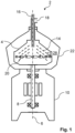
- Fig. 1 schematically illustrates a cross section through a centrifugal separator 2 according to embodiments.
- the centrifugal separator 2 is a high speed separator provided with nozzle outlets for a separated sludge phase from a separator bowl 4 of the centrifugal separator.
- the centrifugal separator 2 may be any such separator, the basic features of which will be described with reference to Fig. 1 .
- the centrifugal separator 2 comprises a separator bowl 4 being configured to rotate about a rotational axis 6.
- the separator bowl 4 is mounted on a spindle 8.
- the spindle 8 is supported in a stationary housing 10 of the centrifugal separator 2, e.g. via two bearings.
- a drive arrangement is configured to rotate the spindle 8 and the separator bowl 4 about the rotational axis 6.
- the spindle 8 forms part of the drive arrangement.
- the drive arrangement comprises an electric motor and a rotor of the electric motor forms part of the spindle 8.
- the drive arrangement may instead be connected to the spindle 8.
- Such alternative embodiments may comprise an electric motor connected via a transmission, e.g. comprising cog wheels or a belt drive, to the spindle 8.
- the separator bowl 4 delimits therein a separation space 12.
- a separation aid configured to improve separation of liquid mixture.
- the separation aid schematically indicated in the illustrated embodiments, comprises a stack of frusto-conical separation discs 14.
- the separation discs 14 provide for an efficient separation of the liquid mixture into at least a light phase and a sludge phase during use of the centrifugal separator 2.
- the stack of frusto-conical separation discs 14 is fitted coaxially with the rotational axis 6.
- the centrifugal separator 2 further comprises an inlet 16 for the liquid mixture and a light phase outlet 18 for the separated light phase.
- the inlet 16 and the light phase outlet 18 are arranged at an upper end of the separator bowl 4.
- One or both of the inlet 16 and the light phase outlet 18 may alternatively be arranged at a lower end of the separator bowl 4.
- a number of nozzle members 20 for discharging the separated sludge phase from the separation space 12 and the separator bowl 4 are arranged at a periphery of the separator bowl 4.
- the number of nozzle members 20 may be, e.g. 7 - 28.
- the housing 10 may comprise a number of individual parts and thus, may be assembled from several parts.
- the housing 10 may comprise a hood 22 enclosing the separator bowl 4. From the nozzle members 20, the sludge phase is discharged into a space 28 outside the separator bowl 4. The space 28 is formed between the bowl 4 and the hood 22. The sludge phase is lead out from the space 28 via a non-shown sludge outlet.
- the separator bowl 4 is rotated at high speed, such as several thousands of rpm, and a solid matter containing liquid mixture is conducted via the inlet 16 to the centre of the separator bowl 4 and from there into the separation space 12.
- the solid matter takes the form of small particles suspended in the liquid mixture.
- the liquid mixture may comprise one or more liquids. That is, in addition to the solid matter and a first liquid, the liquid mixture may comprise a further liquid of higher density than the first liquid.
- the liquid mixture is separated into the light phase and the sludge phase in the stack of frusto-conical separation discs 14.
- the light phase is a liquid substantially free of any solid matter and the sludge phase is a solid matter containing liquid.
- the separated light phase flows radially inwardly between the separation discs 14 towards the vertical axis 6 of rotation and out of the separator bowl 4 via the light phase outlet 18.
- the separated solid matter is transported radially outwardly between the separation discs 14 towards a periphery of the separation space 12.
- the solid matter flows out of the separator bowl 4 as a part of the sludge phase via the nozzle members 20 arranged at the periphery of the separator bowl 4.
- the sludge phase may include one or more of the light phase and/or a separated heavy liquid phase.
- the nozzle members 20 form an open passage from the separation space 12 to the space 28 outside the bowl 4.
- the centrifugal separator 2 comprises wear protection measures, which now will be discussed with reference to Figs. 2a - 6d .
- Figs. 2a and 2c illustrate partial views of a separator bowl 4, such as a separator bowl 4 of the centrifugal separator 2 discussed above with reference to Fig. 1 .
- Fig. 2b illustrates a cross section through a portion of the separator bowl 4 along line IIb - Ilb in Fig. 2a .
- the separator bowl 4 is provided with peripherally arranged nozzle members 20.
- nozzle members 20 In Figs. 2a and 2b one of the nozzle members 20 is shown.
- the nozzle member 20 forms a nozzle outlet 24 providing a passage 26 from the separation space 12 to a space 28 outside the separator bowl 4.
- the passage 26 is always open. That is, the nozzle member 20, the nozzle outlet 24 and the passage 26 are arranged for continuous discharge of solid phase.
- the nozzle member 20 comprises two main portions, an inner portion 21 and an outer portion 23.
- the outer portion 23 includes a radially outer portion of the passage 26 and the nozzle outlet 24 and may be made from a wear resistant material, such as a carbide or tungsten.
- the outer portion 24 may be exchangeable from an outside of the separator bowl 4 and may be fastened via e.g. a bayonet coupling to the inner portion 21.
- the nozzle member may comprise only one part or more than two parts.
- nozzle member may comprise only one part or more than two parts.
- the nozzle outlet 24 may be provided in a separate exchangeable part, which may be fitted in the outer portion 23 of the nozzle member 20 shown in the illustrated embodiments or in a different kind of nozzle member.
- a protective member 30 is arranged downstream of each nozzle outlet 24 at an outer periphery of the separator bowl 4.
- the rotational direction of the separator bowl is indicated with a broad arrow.
- the nozzle outlet 24 of each nozzle member 20 is directed rearwardly in relation to the rotational direction of the separator bowl 4. Downstream the nozzle outlet 24 is thus, behind the nozzle outlet 24 seen along the rotational direction of the separator bowl 4.
- the nozzle outlet 24 may be directed rearwardly at a right angle to a radial direction of the separator bowl 4 or at an acute angle to the radial direction as shown in Fig. 2b . Accordingly, the jet of the sludge phase discharged through the nozzle outlet 24 has at least one directional component extending in parallel to a tangent of the separator bowl 4.
- the protective member 30 is arranged on the separator bowl 4 to protect the outer surface of the separator bowl 4 against wear from abrasive sludge phase discharged from the nozzle outlet 24.
- the protective member 30 is exchangeable. Accordingly, if worn, the protective member 30 may be exchanged for an unworn protective member 30.
- the body of the separator bowl 4 does not wear or at least does wear to a considerably lesser degree than if it were not provided with the protective member 30.
- the nozzle member 20 secures the protective member 30 in relation to the separator bowl 4.
- Fig. 2c shows the protective member 30 being about to be positioned in its dedicated position at the outer periphery of the separator bowl 4.
- a new protective member 30 is performed by positioning it in its dedicated position at the outer periphery of the separator bowl 4 while the nozzle member 20, or at least part thereof such as the outer portion 23, is removed from the separator bowl 4.
- the protective member 30 is partially positioned, still covering the opening 25 (indicated with a broken line) in the separator bowl 4, into which the outer portion 23 of the nozzle member 20 fits.
- the nozzle member 20 is mounted in the separator bowl 4, such as the outer portion 23 of the nozzle member 20 being mounted in its inner portion 21. The nozzle member 20 prevents the protective member 30 from coming loose from the separator bowl 4.
- the outer portion 23 of the protective member 30 secures the protective member 30 in relation to the separator bowl 4.
- the nozzle member 20 adjoins the protective member 30.
- the nozzle member 20 prevents the protective member 30 from moving beyond the nozzle member 20 and secures the protective member 30 to the separator bowl 4.
- the nozzle member 20 may be arranged in adjoining abutment with the protective member 30 to ensure secure positioning of the protective member 30.
- a surface 32 of the protective member 30 facing radially inwardly towards a body 34 of the separator bowl 4 is arranged at an angle ⁇ within a range of 10 - 50 degrees in relation to a tangent of the outer periphery of the separator bowl 4 at the nozzle member 20.
- the angle ⁇ has its vertex at the nozzle member 20. Accordingly, the protective member 30 extends into the body 34 of the separator bowl 4.
- a related surface 36 of the body 34 of the separator bowl 4, opposite to the surface 32 of the protective member 30 facing towards the body 34 of the separator bowl 4, comprises a directional component along a radial direction of the separator bowl 4.
- the nozzle member 20 secures the protective member 30 along a rotational direction of the separator bowl 4 as well as along the radial direction of the separator bowl 4.
- the nozzle member 20 prevents displacement of the protective member 30 along the related surface 36 of the separator bowl 4.
- the protective member 30 is arranged in a slot 44 extending from the nozzle member 20 into the body 34 of the separator bowl 4.
- the protective member 30 positioned in the slot 44 is thus, arranged in the body 34 of the separator bowl 4.
- the related surface 36 of the body 34 of the separator bowl 4 forms a radially inner surface of the slot 44.
- the protective member 30 comprises a wedge-shaped body 38.
- a vertex end portion 40 of the wedge-shaped body 38 is configured to be arranged at the nozzle member 20 and an opposite wide end portion 42 of the wedge-shaped body 38 is configured to be arranged at a distance from the nozzle member 20.
- the protective member 30 is thus, devised to widen in a direction downstream of the nozzle outlet 24.
- the wedge-shaped body 38 may have a curved outer surface to generally follow the outer radius of the separator bowl 4.
- the wedge-shaped body 38 of the protective member 30 may comprises at least one lateral projection 46 and the body 34 of the separator bowl 4 may be provided with at least one groove 48 extending substantially perpendicularly to the slot 44.
- the at least one lateral projection 46 engages with the at least one groove 48. In this manner, the at least one lateral projection 46 engaging with the at least one groove 48 contributes to securing the protective member 30 to the separator bowl 4 in the slot 44.
- Fig. 2c it is shown how the lateral projection 46 extending around part of the body 38 of the protective member 30 is inserted and slid into the groove 48 extending around the perimeter of the slot 44.
- the nozzle outlet 24 may be arranged inside the outer periphery of the separator bowl 4. In this manner, the nozzle member 20 may be arranged, at least to a large extent, within the outer periphery of the separator bowl 4. Thus, it is avoided that the nozzle member 20 causes noise during high speed rotation of the separator bowl 4. Such noise would occur if the nozzle member 20 extends beyond the outer periphery of the separator bowl 4 to a certain extent.
- Figs. 3a - 3c illustrate a protective member 30 according to embodiments.
- the protective member 30 may be a protective member 30 as discussed above with reference to Figs. 2a - 2c .
- the protective member 30 is provided for a centrifugal separator according to aspects and/or embodiments discussed herein.
- the protective member 30 comprising a wedge-shaped body 38.
- a vertex end portion 40 of the wedge-shaped body 38 is configured to be arranged at a nozzle member of a separator bowl of the centrifugal separator.
- An opposite wide end portion 42 of the wedge-shaped body 38 is configured to be arranged at a distance from the nozzle member.
- the vertex end portion 40 of the wedge-shaped body 38 has an outer contour, which is shaped such that it is configured to border to the nozzle member.
- the outer contour has a radius R adapted to a radius of the relevant nozzle member. Accordingly, the vertex end portion 40 of the wedge-shaped body 38 may be arranged in adjoining abutment with the nozzle member.
- the opposite wide end portion 42 of the wedge-shaped body 38 is configured to be arranged at a distance from the nozzle member firstly, due to the fact that it is arranged opposite to the vertex end portion 40. Secondly, the opposite wide end portion 42 may be shaped such that it fits into a slot in the separator bowl. In the illustrated embodiments, the opposite wide end portion 42 has an outer contour adapted to an inner end portion of the slot in the separator bowl. For instance, the wide end portion 42 of the wedge-shaped body 38 may have a rounded outer contour perpendicular to the wedge-shape.
- the wedge-shaped body 38 may comprise at least one lateral projection 46.
- the at least one projection 46 may engage with a corresponding groove in a body of the separator bowl.
- the protective member 30 may be devised for being held by the at least one lateral projection 46 in the separator bowl, as discussed above inter alia with reference to Fig. 2c .
- the wedge-shaped body 38 of the protective member 30 may comprise a surface portion 50 extending perpendicularly to the at least one lateral projection 46.
- a relief surface 52 may be arranged between the at least one lateral projection 46 and the surface portion 50 extending perpendicularly to the at least one lateral projection 46.
- manufacturing of the protective member 30 may be facilitated. Namely, by providing the relief surface 52 between the lateral projection 46 and the surface portion 50 extending perpendicularly to the lateral projection 46, the surface portion 50 may be shaped without a transition between the lateral projection 46 and the surface portion 50 impeding such shaping.
- the relief surface 52 forms part of a recess into the body 38 of the protective member 30 between the at least one lateral projection 46 and the surface portion 50.
- the wedge-shaped body 38 of the protective member 30 may be produced by additive manufacturing. In this manner, a complex shape of the protective member 30 may be produced. Moreover, the protective member 30 may be manufactured from wear resistant materials, which may be difficult to subject to machining.
- the final tolerances of e.g. the lateral projection 46 and the surface portion 50 may be achieved after additive manufacturing, e.g. by grinding.
- the wedge-shaped body 38 of the protective member 30 may be produced by any other suitable manufacturing method, such as casting, machining, etc.
- Figs. 4a and 4b illustrate partial views of a separator bowl 4, such as a separator bowl 4 of the centrifugal separator 2 discussed above with reference to Fig. 1 .
- Fig. 4a shows a front view
- Fig. 4b shows a side view of the separator bowl 4 along line IVb - Ivb in Fig. 4a .
- the separator bowl 4 is provided with peripherally arranged nozzle members 20.
- Each nozzle member 20 forms a nozzle outlet 24 providing a passage from the separation space inside the separation bowl 4 to a space outside the separator bowl 4.
- a protective member 30 (marked with hatchings) is arranged downstream of each nozzle outlet 24 at an outer periphery of the separator bowl 4.
- FIG. 4a an opening 25 in the separator bowl 4, into which at least part of the nozzle member 20 fits is shown.
- a corresponding opening 27 for the nozzle member 20 is provided in the protective member 30.
- the nozzle member 20 is shown mounted in the separator bowl 4.
- the protective member 30 comprises a sheet 54 arranged along the outer periphery of the separator bowl 4.
- the sheet 54 protects the outer surface of the separator bowl 4 against wear.
- the sheet 54 may be a sheet metal with good abrasive properties.
- a surface 32 of the protective member 30 facing radially inwardly towards a body 34 of the separator bowl 4 is arranged at an angle of 0 degrees in relation to a tangent of the outer periphery of the separator bowl 4 at the nozzle member 20.
- the nozzle member 20 secures the protective member 30 in relation to the separator bowl 4.
- the nozzle member 20 secures the protective member 30 in the circumferential direction of the separator bowl 4, i.e. along a rotational direction of the separator bowl 4. This is achieved by the nozzle member 20 at least partially extending through the protective member 30 in a radial direction of the separator bowl 4.
- the nozzle member 20 is mounted in the separator bowl 4, such as the outer portion 23 of the nozzle member 20 being mounted in its inner portion 21.
- the protective member 30 is positioned on the outer periphery of the separator bowl 4 and then the nozzle member 20, such as an outer portion 23 of the nozzle member 20, is mounted in the separator bowl 4.
- the nozzle member 20, when mounted in the opening 25 of the separator bowl 4 extends at least partially through the opening 27 provided through the sheet 54 of the protective member 30.
- the nozzle member 20 secures the protective member 30 in the circumferential direction of the separator bowl 4.
- the nozzle member may be at least partially secured in a radial direction of the separator bowl by the protective member.
- the nozzle member may engage with the protective member via a bayonet coupling. Since the nozzle member extends into the body of the separator bowl, radially inside the protective member, also in such embodiments, the nozzle member secures the protective member in a circumferential direction of the separator bowl.
- the nozzle outlet 24 is arranged outside the outer periphery of the separator bowl 4 and radially outside the protective member 30. In this manner, the nozzle outlet 24 is positioned for unimpeded ejection of the sludge phase through the nozzle outlet 24 into the space outside the separator bowl 4.
- the protective member 30 is secured in a radial direction of the separator bowl 4 with at least two fastening elements 56 at the outer periphery of the separator bowl 4. In this manner, the protective member 30 is held in position at the outer periphery of the separator bowl 4 together with the nozzle member 20, in radial and circumferential directions.
- the at least two fastening elements 56 comprise two rails attached to the outer periphery of the separator bowl 4 axially above and below the opening 25 for the nozzle member 20.
- the protective member 30 is slid under the two rails. Thus, the securing in the radial direction of the protective member 30 is achieved.
- the protective member 30 extends outside the nozzle member 20 in an axial direction of the separator bowl 4. In this manner, a broad area of the outer surface of the separator bowl 4, in the axial direction, may be protected by the protective member 30. This may be advantageous if the nozzle outlet 24 is worn to such a degree that the jet of the sludge phase ejected through the nozzle outlet 24 has a wide spray angle.
- Fig. 5 illustrates embodiments of a protective member 30.
- the protective member 30 resembles in much the protective member 30 discussed above with reference to Figs. 4a and 4b .
- the protective member 30 comprises a sheet 54.
- the sheet 54 of the protective member 30 is configured to be arranged along the outer periphery of a separator bowl.
- the nozzle member (not shown) secures the protective member 30 in the circumferential direction of the separator bowl.
- the protective member 30 is secured in the radial direction of the separator bowl with at least two fastening elements at the outer periphery of the separator bowl 4.
- the at least two fastening elements comprise a number of screws (not shown), which extended through holes 58 provided in the sheet 54.
- screws are relied upon to secure the protective member 30 in a radial direction of the separator bowl, the protective member 30 is secured in a circumferential direction by the nozzle member extending through the opening 27 in the sheet 54.
- Figs. 6a - 6d illustrate a separator bowl 4 and a protective member 30 according to embodiments.
- Fig. 6a illustrates a partial view of the separator bowl 4, such as a separator bowl 4 of the centrifugal separator 2 discussed above with reference to Fig. 1 .
- Fig. 6b illustrates a cross section through a portion of the separator bowl 4 along line VIb - VIb in Fig. 6a.
- Figs. 6c and 6d illustrate two perspective views of the protective member 30.
- the protective member 30 of these embodiments resembles in much the protective member 30 according to the embodiments discussed above with reference to Figs. 2a - 3c .
- the manner in which the protective member 30 is connected to the separator bowl 4 resembles in much the manner discussed above with reference to Figs. 2a - 3c . Accordingly, in the following, mainly the differences between these embodiments and those of Figs. 2a - 3c will be discussed.
- the separator bowl 4 is provided with peripherally arranged nozzle members 20.
- nozzle members 20 In Figs. 6a and 6b an outer portion 23 of the nozzle members 20 is shown.
- the nozzle member 20 forms a nozzle outlet 24 providing a passage 26.
- a protective member 30 is arranged downstream of each nozzle outlet 24 at an outer periphery of the separator bowl 4.
- the nozzle member 20 secures the protective member 30 in relation to the separator bowl 4. There is no additional member required for securing the protective member 30 to the separator bowl 4.
- the nozzle member 20 extends partially trough the protective member 30.
- An opening 27 is provided in the protective member 30 through which part of the nozzle member 20 extends.
- the nozzle member 20 prevents the protective member 30 from moving in a circumferential direction of the separator bowl 4.
- the body 34 of the separator bowl 4 is provided with a slot 44 extending around the nozzle member 20.
- the protective member 30 is positioned in the slot 44.
- a body 38 of the protective member 30 comprises two protrusions 64, 66.
- the slot 44 comprises two recesses 60, 62.
- Each of the two protrusions 64, 66 has a form mating with a respective shape of the two recesses 60, 62.
- each of the two protrusions 64, 66 comprises a lateral projection 46.
- the body 34 of the separator bowl 4, in each of the recesses 60, 62, is provided with a groove 48 extending substantially perpendicularly to the slot 44.
- the lateral projections 46 engage with the grooves 48. This engagement between the projections 46 and the grooves 48 contributes to securing the protective member 30 to the separator bowl 4 in the slot 44.
- a surface 32 of the protective member 30 facing radially inwardly towards the body 34 of the separator bowl 4 is arranged at an angle ⁇ within a range of 10 - 50 degrees in relation to a tangent of the outer periphery of the separator bowl 4 at the nozzle member 20.
- the angle ⁇ has its vertex at the nozzle member 20, i.e. in a region of the nozzle member 20.
- the surface 32 may be a surface of one of the protrusions 60, 62.
- a related surface 36 of the body 34 of the separator bowl 4, opposite to the surface 32 of the protective member 30 facing towards the body 34 of the separator bowl 4, comprises a directional component along a radial direction of the separator bowl 4.
- the nozzle member 20 secures the protective member 30 along a rotational direction of the separator bowl 4 as well as along the radial direction of the separator bowl 4.
- the nozzle outlet 24 is arranged inside the outer periphery of the separator bowl 4.
- the protective member 30 extends outside the nozzle member 20 in an axial direction of the separator bowl 4. In this manner, a broad area of the outer surface of the separator bowl 4, in the axial direction, may be protected against wear by the protective member 30. This may be advantageous if the nozzle outlet 24 is worn to such a degree that the jet of the sludge phase ejected through the nozzle outlet 24 has a wide spray angle.
Landscapes
- Centrifugal Separators (AREA)
Claims (15)
- Zentrifugalabscheider (2), umfassend eine Abscheiderschale (4), die darin einen Abscheideraum (12) abgrenzt und die dafür konfiguriert ist, sich um eine Rotationsachse (6) zu drehen, undDüsenelemente (20), die peripher an der Abscheiderschale (4) angeordnet sind, wobeijedes Düsenelement (20) einen Düsenauslass (24) bildet, der einen Durchgang (26) von dem Abscheideraum (12) in einen Raum (28) außerhalb der Abscheiderschale (4) bereitstellt, und wobeider Zentrifugalabscheider (2) ein Schutzelement (30) umfasst, das stromabwärts von jedem Düsenauslass (24) an einer äußeren Peripherie der Abscheiderschale (4) angeordnet ist,dadurch gekennzeichnet, dassdas Düsenelement (20) das Schutzelement (30) in Bezug auf die Abscheiderschale (4) mindestens in einer Umfangsrichtung der Abscheiderschale (4) sichert.
- Zentrifugalabscheider (2) nach Anspruch 1, wobei das Düsenelement (20) an das Schutzelement (30) angrenzt und/oder sich mindestens teilweise durch das Schutzelement (30) in einer radialen Richtung der Abscheiderschale (4) erstreckt.
- Zentrifugalabscheider (2) nach Anspruch 1 oder 2, wobei eine Oberfläche (32) des Schutzelements (30), die radial nach innen zu einem Körper (34) der Abscheiderschale (4) gewandt ist, in einem Winkel (α) innerhalb eines Bereichs von 0 bis 50 Grad in Bezug auf eine Tangente der äußeren Peripherie der Abscheiderschale (4) an dem Düsenelement (20) angeordnet ist, wobei der Winkel (α) seinen Scheitel an dem Düsenelement (20) aufweist.
- Zentrifugalabscheider (2) nach Anspruch 3, wobei der Winkel (α) innerhalb eines Bereichs von 10 bis 50 Grad in Bezug auf die Tangente der äußeren Peripherie der Abscheiderschale (4) liegt, und wobei das Schutzelement (30) einen keilförmigen Körper (38) umfasst, wobei ein Scheitelendabschnitt (40) des keilförmigen Körpers (38) dafür konfiguriert ist, an dem Düsenelement (20) angeordnet zu sein, und ein entgegengesetzter breiter Endabschnitt (42) des keilförmigen Körpers (38) dafür konfiguriert ist, mit einem Abstand von dem Düsenelement (20) angeordnet zu sein.
- Zentrifugalabscheider (2) nach einem der vorhergehenden Ansprüche, wobei das Schutzelement (30) in einem Schlitz (44) angeordnet ist, der sich von dem Düsenelement (20) in einen Körper (34) der Abscheiderschale (4) erstreckt.
- Zentrifugalabscheider (2) nach den Ansprüchen 4 und 5, wobei der keilförmige Körper (38) des Schutzelements (30) mindestens einen seitlichen Vorsprung (46) umfasst und der Körper der Abscheiderschale (4) mit mindestens einer Nut (48) versehen ist, die sich im Wesentlichen senkrecht zu dem Schlitz (44) erstreckt, und wobei der mindestens eine seitliche Vorsprung (46) in die mindestens eine Nut (48) eingreift.
- Zentrifugalabscheider (2) nach einem der vorhergehenden Ansprüche, wobei der Düsenauslass (24) innerhalb der äußeren Peripherie der Abscheiderschale (4) angeordnet ist.
- Zentrifugalabscheider (2) nach einem der Ansprüche 1 bis 3, wobei das Schutzelement (30) eine Lage (54) umfasst, die entlang der äußeren Peripherie der Abscheiderschale (4) angeordnet ist.
- Zentrifugalabscheider (2) nach Anspruch 8, wobei das Schutzelement (30) in einer radialen Richtung der Abscheiderschale (4) mit mindestens zwei Befestigungselementen (56) an der äußeren Peripherie der Abscheiderschale (4) gesichert ist.
- Zentrifugalabscheider (2) nach Anspruch 8 oder 9, wobei der Düsenauslass (24) mindestens teilweise außerhalb der äußeren Peripherie der Abscheiderschale (4) und radial außerhalb des Schutzelements (30) angeordnet ist.
- Zentrifugalabscheider (2) nach einem der vorhergehenden Ansprüche, wobei sich das Schutzelement (30) außerhalb des Düsenelements (20) in einer axialen Richtung der Abscheiderschale (4) erstreckt.
- Schutzelement (30) für einen Zentrifugalabscheider (2) nach einem der Ansprüche 1 bis 7, wobei das Schutzelement (30) einen keilförmigen Körper (38) umfasst, wobei ein Scheitelendabschnitt (40) des keilförmigen Körpers (38) dafür konfiguriert ist, an dem Düsenelement (20) angeordnet zu sein, dadurch, dass die Außenkontur des Scheitelendabschnitts 40 einen Radius R aufweist, der an einen Radius des Düsenelements (20) angepasst ist, und wobei ein entgegengesetzter breiter Endabschnitt (42) des keilförmigen Körpers (38) dafür konfiguriert ist, mit einem Abstand von dem Düsenelement (20) angeordnet zu sein.
- Schutzelement (30) nach Anspruch 12, wobei der keilförmige Körper (38) mindestens einen seitlichen Vorsprung (46) umfasst.
- Schutzelement (30) nach Anspruch 13, wobei der keilförmige Körper (38) des Schutzelements (30) einen Oberflächenabschnitt (50) umfasst, der sich senkrecht zu dem mindestens einen seitlichen Vorsprung (46) erstreckt, und wobei eine Relieffläche (52) zwischen dem mindestens einen seitlichen Vorsprung (46) und dem Oberflächenabschnitt (50) angeordnet ist, der sich senkrecht zu dem mindestens einen seitlichen Vorsprung (46) erstreckt.
- Schutzelement (30) nach einem der Ansprüche 11 bis 14, wobei der keilförmige Körper (38) durch additive Fertigung hergestellt wird.
Priority Applications (6)
| Application Number | Priority Date | Filing Date | Title |
|---|---|---|---|
| EP21163064.5A EP4059608B1 (de) | 2021-03-17 | 2021-03-17 | Fliehkraftabscheider und schutzelement |
| US18/280,076 US20240066529A1 (en) | 2021-03-17 | 2022-02-18 | Centrifugal separator and protective member |
| CA3210749A CA3210749A1 (en) | 2021-03-17 | 2022-02-18 | Centrifugal separator and protective member |
| CN202280018552.8A CN116963840A (zh) | 2021-03-17 | 2022-02-18 | 离心分离器和保护部件 |
| BR112023015396A BR112023015396A2 (pt) | 2021-03-17 | 2022-02-18 | Separador centrífugo, e, membro protetor para um separador centrífugo |
| PCT/EP2022/054051 WO2022194487A1 (en) | 2021-03-17 | 2022-02-18 | Centrifugal separator and protective member |
Applications Claiming Priority (1)
| Application Number | Priority Date | Filing Date | Title |
|---|---|---|---|
| EP21163064.5A EP4059608B1 (de) | 2021-03-17 | 2021-03-17 | Fliehkraftabscheider und schutzelement |
Publications (2)
| Publication Number | Publication Date |
|---|---|
| EP4059608A1 EP4059608A1 (de) | 2022-09-21 |
| EP4059608B1 true EP4059608B1 (de) | 2025-02-19 |
Family
ID=74947115
Family Applications (1)
| Application Number | Title | Priority Date | Filing Date |
|---|---|---|---|
| EP21163064.5A Active EP4059608B1 (de) | 2021-03-17 | 2021-03-17 | Fliehkraftabscheider und schutzelement |
Country Status (6)
| Country | Link |
|---|---|
| US (1) | US20240066529A1 (de) |
| EP (1) | EP4059608B1 (de) |
| CN (1) | CN116963840A (de) |
| BR (1) | BR112023015396A2 (de) |
| CA (1) | CA3210749A1 (de) |
| WO (1) | WO2022194487A1 (de) |
Families Citing this family (1)
| Publication number | Priority date | Publication date | Assignee | Title |
|---|---|---|---|---|
| DE102024112819B3 (de) * | 2024-05-07 | 2025-09-04 | Flottweg Se | Zentrifugentrommel, Auslassanordnung, Umlenkbauteil und Zentrifuge |
Family Cites Families (11)
| Publication number | Priority date | Publication date | Assignee | Title |
|---|---|---|---|---|
| DK148736C (da) * | 1981-12-09 | 1986-03-03 | Alfa Laval Separation As | Transportsnegl, navnlig til en dekantercentrifuge |
| DE10065530A1 (de) | 2000-12-28 | 2002-07-04 | Bosch Gmbh Robert | Einrichtung zur Stromerzeugung und zum Abschatten bei Kraftfahrzeugen |
| DK175539B1 (da) * | 2002-03-14 | 2004-11-29 | Alfa Laval Copenhagen As | Dekantercentrifuge med slidforstærkning i indlöb |
| DE20219551U1 (de) | 2002-12-16 | 2004-04-29 | Westfalia Separator Ag | Zentrifuge, insbesondere Separator, mit Feststoff-Austrittsdüsen |
| DE102015001246B3 (de) * | 2015-01-31 | 2016-06-16 | Audi Ag | Reinigungsvorrichtung für eine mechanische Reinigung einer Gasdüse eines Schutzgas-Schweißbrenners |
| MX2018011526A (es) * | 2016-03-24 | 2019-07-04 | Fluid Quip Inc | Rotor centrífugo con boquillas alternadas para usarse en una centrífuga de disco de boquillas. |
| US20180008990A1 (en) * | 2016-07-07 | 2018-01-11 | Tobi D. Mengle | Centrifugal mechanical separator produced by additive manufacturing |
| CN205761838U (zh) * | 2016-07-17 | 2016-12-07 | 江苏巨能机械有限公司 | 喷嘴保护结构 |
| CN205868566U (zh) * | 2016-08-11 | 2017-01-11 | 山东金威力石油装备制造有限公司 | 一种卧螺离心机 |
| CN207446527U (zh) * | 2017-06-08 | 2018-06-05 | 坚纳森(青岛)机械有限公司 | 离心机的喷嘴以及离心机 |
| CN212215910U (zh) * | 2020-05-19 | 2020-12-25 | 福建省深蓝生物科技有限公司 | 一种螺旋离心机 |
-
2021
- 2021-03-17 EP EP21163064.5A patent/EP4059608B1/de active Active
-
2022
- 2022-02-18 CN CN202280018552.8A patent/CN116963840A/zh active Pending
- 2022-02-18 WO PCT/EP2022/054051 patent/WO2022194487A1/en not_active Ceased
- 2022-02-18 BR BR112023015396A patent/BR112023015396A2/pt unknown
- 2022-02-18 CA CA3210749A patent/CA3210749A1/en active Pending
- 2022-02-18 US US18/280,076 patent/US20240066529A1/en active Pending
Also Published As
| Publication number | Publication date |
|---|---|
| US20240066529A1 (en) | 2024-02-29 |
| EP4059608A1 (de) | 2022-09-21 |
| WO2022194487A1 (en) | 2022-09-22 |
| BR112023015396A2 (pt) | 2023-09-26 |
| CN116963840A (zh) | 2023-10-27 |
| CA3210749A1 (en) | 2022-09-22 |
Similar Documents
| Publication | Publication Date | Title |
|---|---|---|
| EP1993702B1 (de) | Zentrifugalabscheider | |
| EP1984093B1 (de) | Zentrifugalabscheider | |
| EP1991337B1 (de) | Zentrifugalabscheider | |
| US4543111A (en) | Dust separator | |
| US7083565B2 (en) | Solid-bowl centrifuge having a disk stack on the drum cover | |
| JP2017006909A (ja) | デカンタ型遠心分離機 | |
| EP4059608B1 (de) | Fliehkraftabscheider und schutzelement | |
| US4844354A (en) | Centrifugal refining crusher | |
| IE60187B1 (en) | A rotary crusher having self-protecting projection vanes | |
| CA3018847C (en) | Centrifuge rotor with staggered nozzles for use in a disc nozzle centrifuge | |
| JP4382992B2 (ja) | 反作用駆動型遠心ロータ | |
| JP7227038B2 (ja) | 遠心分離装置 | |
| JP6006453B1 (ja) | 遠心分離装置 | |
| US5074995A (en) | Apparatus for separating particles from a pulp flow and dividing the flow into fractions | |
| JP7416588B2 (ja) | スクリーン装置及びスクリーン装置用のロータ | |
| AU2024378075A1 (en) | Centrifuging drum of a centrifuge and centrifuge having such a centrifuging drum | |
| WO2005123261A1 (en) | An arrangement in a centrifugal separator | |
| JP2020121276A (ja) | 遠心分離装置 |
Legal Events
| Date | Code | Title | Description |
|---|---|---|---|
| PUAI | Public reference made under article 153(3) epc to a published international application that has entered the european phase |
Free format text: ORIGINAL CODE: 0009012 |
|
| STAA | Information on the status of an ep patent application or granted ep patent |
Free format text: STATUS: THE APPLICATION HAS BEEN PUBLISHED |
|
| AK | Designated contracting states |
Kind code of ref document: A1 Designated state(s): AL AT BE BG CH CY CZ DE DK EE ES FI FR GB GR HR HU IE IS IT LI LT LU LV MC MK MT NL NO PL PT RO RS SE SI SK SM TR |
|
| STAA | Information on the status of an ep patent application or granted ep patent |
Free format text: STATUS: REQUEST FOR EXAMINATION WAS MADE |
|
| 17P | Request for examination filed |
Effective date: 20230222 |
|
| RBV | Designated contracting states (corrected) |
Designated state(s): AL AT BE BG CH CY CZ DE DK EE ES FI FR GB GR HR HU IE IS IT LI LT LU LV MC MK MT NL NO PL PT RO RS SE SI SK SM TR |
|
| GRAP | Despatch of communication of intention to grant a patent |
Free format text: ORIGINAL CODE: EPIDOSNIGR1 |
|
| STAA | Information on the status of an ep patent application or granted ep patent |
Free format text: STATUS: GRANT OF PATENT IS INTENDED |
|
| INTG | Intention to grant announced |
Effective date: 20241025 |
|
| P01 | Opt-out of the competence of the unified patent court (upc) registered |
Free format text: CASE NUMBER: APP_59610/2024 Effective date: 20241105 |
|
| GRAS | Grant fee paid |
Free format text: ORIGINAL CODE: EPIDOSNIGR3 |
|
| GRAA | (expected) grant |
Free format text: ORIGINAL CODE: 0009210 |
|
| STAA | Information on the status of an ep patent application or granted ep patent |
Free format text: STATUS: THE PATENT HAS BEEN GRANTED |
|
| AK | Designated contracting states |
Kind code of ref document: B1 Designated state(s): AL AT BE BG CH CY CZ DE DK EE ES FI FR GB GR HR HU IE IS IT LI LT LU LV MC MK MT NL NO PL PT RO RS SE SI SK SM TR |
|
| REG | Reference to a national code |
Ref country code: GB Ref legal event code: FG4D |
|
| REG | Reference to a national code |
Ref country code: CH Ref legal event code: EP |
|
| REG | Reference to a national code |
Ref country code: IE Ref legal event code: FG4D |
|
| REG | Reference to a national code |
Ref country code: DE Ref legal event code: R096 Ref document number: 602021026232 Country of ref document: DE |
|
| PGFP | Annual fee paid to national office [announced via postgrant information from national office to epo] |
Ref country code: AT Payment date: 20250417 Year of fee payment: 5 |
|
| REG | Reference to a national code |
Ref country code: NL Ref legal event code: MP Effective date: 20250219 |
|
| PG25 | Lapsed in a contracting state [announced via postgrant information from national office to epo] |
Ref country code: RS Free format text: LAPSE BECAUSE OF FAILURE TO SUBMIT A TRANSLATION OF THE DESCRIPTION OR TO PAY THE FEE WITHIN THE PRESCRIBED TIME-LIMIT Effective date: 20250519 |
|
| PG25 | Lapsed in a contracting state [announced via postgrant information from national office to epo] |
Ref country code: FI Free format text: LAPSE BECAUSE OF FAILURE TO SUBMIT A TRANSLATION OF THE DESCRIPTION OR TO PAY THE FEE WITHIN THE PRESCRIBED TIME-LIMIT Effective date: 20250219 |
|
| PG25 | Lapsed in a contracting state [announced via postgrant information from national office to epo] |
Ref country code: PL Free format text: LAPSE BECAUSE OF FAILURE TO SUBMIT A TRANSLATION OF THE DESCRIPTION OR TO PAY THE FEE WITHIN THE PRESCRIBED TIME-LIMIT Effective date: 20250219 |
|
| PG25 | Lapsed in a contracting state [announced via postgrant information from national office to epo] |
Ref country code: ES Free format text: LAPSE BECAUSE OF FAILURE TO SUBMIT A TRANSLATION OF THE DESCRIPTION OR TO PAY THE FEE WITHIN THE PRESCRIBED TIME-LIMIT Effective date: 20250219 |
|
| REG | Reference to a national code |
Ref country code: LT Ref legal event code: MG9D |
|
| PG25 | Lapsed in a contracting state [announced via postgrant information from national office to epo] |
Ref country code: NO Free format text: LAPSE BECAUSE OF FAILURE TO SUBMIT A TRANSLATION OF THE DESCRIPTION OR TO PAY THE FEE WITHIN THE PRESCRIBED TIME-LIMIT Effective date: 20250519 Ref country code: IS Free format text: LAPSE BECAUSE OF FAILURE TO SUBMIT A TRANSLATION OF THE DESCRIPTION OR TO PAY THE FEE WITHIN THE PRESCRIBED TIME-LIMIT Effective date: 20250619 |
|
| PG25 | Lapsed in a contracting state [announced via postgrant information from national office to epo] |
Ref country code: NL Free format text: LAPSE BECAUSE OF FAILURE TO SUBMIT A TRANSLATION OF THE DESCRIPTION OR TO PAY THE FEE WITHIN THE PRESCRIBED TIME-LIMIT Effective date: 20250219 |
|
| PG25 | Lapsed in a contracting state [announced via postgrant information from national office to epo] |
Ref country code: HR Free format text: LAPSE BECAUSE OF FAILURE TO SUBMIT A TRANSLATION OF THE DESCRIPTION OR TO PAY THE FEE WITHIN THE PRESCRIBED TIME-LIMIT Effective date: 20250219 |
|
| PG25 | Lapsed in a contracting state [announced via postgrant information from national office to epo] |
Ref country code: LV Free format text: LAPSE BECAUSE OF FAILURE TO SUBMIT A TRANSLATION OF THE DESCRIPTION OR TO PAY THE FEE WITHIN THE PRESCRIBED TIME-LIMIT Effective date: 20250219 Ref country code: PT Free format text: LAPSE BECAUSE OF FAILURE TO SUBMIT A TRANSLATION OF THE DESCRIPTION OR TO PAY THE FEE WITHIN THE PRESCRIBED TIME-LIMIT Effective date: 20250620 |
|
| PG25 | Lapsed in a contracting state [announced via postgrant information from national office to epo] |
Ref country code: GR Free format text: LAPSE BECAUSE OF FAILURE TO SUBMIT A TRANSLATION OF THE DESCRIPTION OR TO PAY THE FEE WITHIN THE PRESCRIBED TIME-LIMIT Effective date: 20250520 Ref country code: BG Free format text: LAPSE BECAUSE OF FAILURE TO SUBMIT A TRANSLATION OF THE DESCRIPTION OR TO PAY THE FEE WITHIN THE PRESCRIBED TIME-LIMIT Effective date: 20250219 |
|
| REG | Reference to a national code |
Ref country code: AT Ref legal event code: MK05 Ref document number: 1767812 Country of ref document: AT Kind code of ref document: T Effective date: 20250219 |
|
| PG25 | Lapsed in a contracting state [announced via postgrant information from national office to epo] |
Ref country code: SE Free format text: LAPSE BECAUSE OF FAILURE TO SUBMIT A TRANSLATION OF THE DESCRIPTION OR TO PAY THE FEE WITHIN THE PRESCRIBED TIME-LIMIT Effective date: 20250219 |
|
| PG25 | Lapsed in a contracting state [announced via postgrant information from national office to epo] |
Ref country code: SM Free format text: LAPSE BECAUSE OF FAILURE TO SUBMIT A TRANSLATION OF THE DESCRIPTION OR TO PAY THE FEE WITHIN THE PRESCRIBED TIME-LIMIT Effective date: 20250219 |
|
| PG25 | Lapsed in a contracting state [announced via postgrant information from national office to epo] |
Ref country code: DK Free format text: LAPSE BECAUSE OF FAILURE TO SUBMIT A TRANSLATION OF THE DESCRIPTION OR TO PAY THE FEE WITHIN THE PRESCRIBED TIME-LIMIT Effective date: 20250219 |
|
| PG25 | Lapsed in a contracting state [announced via postgrant information from national office to epo] |
Ref country code: IT Free format text: LAPSE BECAUSE OF FAILURE TO SUBMIT A TRANSLATION OF THE DESCRIPTION OR TO PAY THE FEE WITHIN THE PRESCRIBED TIME-LIMIT Effective date: 20250219 |
|
| PG25 | Lapsed in a contracting state [announced via postgrant information from national office to epo] |
Ref country code: AT Free format text: LAPSE BECAUSE OF FAILURE TO SUBMIT A TRANSLATION OF THE DESCRIPTION OR TO PAY THE FEE WITHIN THE PRESCRIBED TIME-LIMIT Effective date: 20250219 |
|
| PG25 | Lapsed in a contracting state [announced via postgrant information from national office to epo] |
Ref country code: CZ Free format text: LAPSE BECAUSE OF FAILURE TO SUBMIT A TRANSLATION OF THE DESCRIPTION OR TO PAY THE FEE WITHIN THE PRESCRIBED TIME-LIMIT Effective date: 20250219 Ref country code: EE Free format text: LAPSE BECAUSE OF FAILURE TO SUBMIT A TRANSLATION OF THE DESCRIPTION OR TO PAY THE FEE WITHIN THE PRESCRIBED TIME-LIMIT Effective date: 20250219 |
|
| REG | Reference to a national code |
Ref country code: CH Ref legal event code: H13 Free format text: ST27 STATUS EVENT CODE: U-0-0-H10-H13 (AS PROVIDED BY THE NATIONAL OFFICE) Effective date: 20251023 |
|
| PG25 | Lapsed in a contracting state [announced via postgrant information from national office to epo] |
Ref country code: RO Free format text: LAPSE BECAUSE OF FAILURE TO SUBMIT A TRANSLATION OF THE DESCRIPTION OR TO PAY THE FEE WITHIN THE PRESCRIBED TIME-LIMIT Effective date: 20250219 |
|
| PG25 | Lapsed in a contracting state [announced via postgrant information from national office to epo] |
Ref country code: SK Free format text: LAPSE BECAUSE OF FAILURE TO SUBMIT A TRANSLATION OF THE DESCRIPTION OR TO PAY THE FEE WITHIN THE PRESCRIBED TIME-LIMIT Effective date: 20250219 |
|
| PG25 | Lapsed in a contracting state [announced via postgrant information from national office to epo] |
Ref country code: LU Free format text: LAPSE BECAUSE OF NON-PAYMENT OF DUE FEES Effective date: 20250317 |
|
| REG | Reference to a national code |
Ref country code: DE Ref legal event code: R097 Ref document number: 602021026232 Country of ref document: DE |
|
| REG | Reference to a national code |
Ref country code: BE Ref legal event code: MM Effective date: 20250331 |
|
| PG25 | Lapsed in a contracting state [announced via postgrant information from national office to epo] |
Ref country code: MC Free format text: LAPSE BECAUSE OF FAILURE TO SUBMIT A TRANSLATION OF THE DESCRIPTION OR TO PAY THE FEE WITHIN THE PRESCRIBED TIME-LIMIT Effective date: 20250219 |
|
| PLBE | No opposition filed within time limit |
Free format text: ORIGINAL CODE: 0009261 |
|
| STAA | Information on the status of an ep patent application or granted ep patent |
Free format text: STATUS: NO OPPOSITION FILED WITHIN TIME LIMIT |
|
| PG25 | Lapsed in a contracting state [announced via postgrant information from national office to epo] |
Ref country code: FR Free format text: LAPSE BECAUSE OF NON-PAYMENT OF DUE FEES Effective date: 20250419 |
|
| PG25 | Lapsed in a contracting state [announced via postgrant information from national office to epo] |
Ref country code: BE Free format text: LAPSE BECAUSE OF NON-PAYMENT OF DUE FEES Effective date: 20250331 |
|
| PG25 | Lapsed in a contracting state [announced via postgrant information from national office to epo] |
Ref country code: CH Free format text: LAPSE BECAUSE OF NON-PAYMENT OF DUE FEES Effective date: 20250331 |
|
| PG25 | Lapsed in a contracting state [announced via postgrant information from national office to epo] |
Ref country code: IE Free format text: LAPSE BECAUSE OF NON-PAYMENT OF DUE FEES Effective date: 20250317 |
|
| 26N | No opposition filed |
Effective date: 20251120 |
|
| GBPC | Gb: european patent ceased through non-payment of renewal fee |
Effective date: 20250519 |
|
| PG25 | Lapsed in a contracting state [announced via postgrant information from national office to epo] |
Ref country code: GB Free format text: LAPSE BECAUSE OF NON-PAYMENT OF DUE FEES Effective date: 20250519 |
|
| PGFP | Annual fee paid to national office [announced via postgrant information from national office to epo] |
Ref country code: DE Payment date: 20260102 Year of fee payment: 6 |