EP4059701A1 - Procédé de fabrication d'un réservoir haute pression, appareil de fabrication d'un réservoir haute pression, et support de stockage non transitoire - Google Patents
Procédé de fabrication d'un réservoir haute pression, appareil de fabrication d'un réservoir haute pression, et support de stockage non transitoire Download PDFInfo
- Publication number
- EP4059701A1 EP4059701A1 EP22161637.8A EP22161637A EP4059701A1 EP 4059701 A1 EP4059701 A1 EP 4059701A1 EP 22161637 A EP22161637 A EP 22161637A EP 4059701 A1 EP4059701 A1 EP 4059701A1
- Authority
- EP
- European Patent Office
- Prior art keywords
- pressure
- molten resin
- cavity
- increasing
- internal pressure
- Prior art date
- Legal status (The legal status is an assumption and is not a legal conclusion. Google has not performed a legal analysis and makes no representation as to the accuracy of the status listed.)
- Granted
Links
Images


Classifications
-
- B—PERFORMING OPERATIONS; TRANSPORTING
- B29—WORKING OF PLASTICS; WORKING OF SUBSTANCES IN A PLASTIC STATE IN GENERAL
- B29C—SHAPING OR JOINING OF PLASTICS; SHAPING OF MATERIAL IN A PLASTIC STATE, NOT OTHERWISE PROVIDED FOR; AFTER-TREATMENT OF THE SHAPED PRODUCTS, e.g. REPAIRING
- B29C70/00—Shaping composites, i.e. plastics material comprising reinforcements, fillers or preformed parts, e.g. inserts
- B29C70/04—Shaping composites, i.e. plastics material comprising reinforcements, fillers or preformed parts, e.g. inserts comprising reinforcements only, e.g. self-reinforcing plastics
- B29C70/28—Shaping operations therefor
- B29C70/40—Shaping or impregnating by compression not applied
- B29C70/42—Shaping or impregnating by compression not applied for producing articles of definite length, i.e. discrete articles
- B29C70/44—Shaping or impregnating by compression not applied for producing articles of definite length, i.e. discrete articles using isostatic pressure, e.g. pressure difference-moulding, vacuum bag-moulding, autoclave-moulding or expanding rubber-moulding
- B29C70/443—Shaping or impregnating by compression not applied for producing articles of definite length, i.e. discrete articles using isostatic pressure, e.g. pressure difference-moulding, vacuum bag-moulding, autoclave-moulding or expanding rubber-moulding and impregnating by vacuum or injection
-
- F—MECHANICAL ENGINEERING; LIGHTING; HEATING; WEAPONS; BLASTING
- F17—STORING OR DISTRIBUTING GASES OR LIQUIDS
- F17C—VESSELS FOR CONTAINING OR STORING COMPRESSED, LIQUEFIED OR SOLIDIFIED GASES; FIXED-CAPACITY GAS-HOLDERS; FILLING VESSELS WITH, OR DISCHARGING FROM VESSELS, COMPRESSED, LIQUEFIED, OR SOLIDIFIED GASES
- F17C1/00—Pressure vessels, e.g. gas cylinder, gas tank, replaceable cartridge
- F17C1/02—Pressure vessels, e.g. gas cylinder, gas tank, replaceable cartridge involving reinforcing arrangements
- F17C1/04—Protecting sheathings
- F17C1/06—Protecting sheathings built-up from wound-on bands or filamentary material, e.g. wires
-
- B—PERFORMING OPERATIONS; TRANSPORTING
- B29—WORKING OF PLASTICS; WORKING OF SUBSTANCES IN A PLASTIC STATE IN GENERAL
- B29C—SHAPING OR JOINING OF PLASTICS; SHAPING OF MATERIAL IN A PLASTIC STATE, NOT OTHERWISE PROVIDED FOR; AFTER-TREATMENT OF THE SHAPED PRODUCTS, e.g. REPAIRING
- B29C70/00—Shaping composites, i.e. plastics material comprising reinforcements, fillers or preformed parts, e.g. inserts
- B29C70/04—Shaping composites, i.e. plastics material comprising reinforcements, fillers or preformed parts, e.g. inserts comprising reinforcements only, e.g. self-reinforcing plastics
- B29C70/28—Shaping operations therefor
- B29C70/40—Shaping or impregnating by compression not applied
- B29C70/42—Shaping or impregnating by compression not applied for producing articles of definite length, i.e. discrete articles
- B29C70/46—Shaping or impregnating by compression not applied for producing articles of definite length, i.e. discrete articles using matched moulds, e.g. for deforming sheet moulding compounds [SMC] or prepregs
- B29C70/48—Shaping or impregnating by compression not applied for producing articles of definite length, i.e. discrete articles using matched moulds, e.g. for deforming sheet moulding compounds [SMC] or prepregs and impregnating the reinforcements in the closed mould, e.g. resin transfer moulding [RTM], e.g. by vacuum
-
- B—PERFORMING OPERATIONS; TRANSPORTING
- B29—WORKING OF PLASTICS; WORKING OF SUBSTANCES IN A PLASTIC STATE IN GENERAL
- B29C—SHAPING OR JOINING OF PLASTICS; SHAPING OF MATERIAL IN A PLASTIC STATE, NOT OTHERWISE PROVIDED FOR; AFTER-TREATMENT OF THE SHAPED PRODUCTS, e.g. REPAIRING
- B29C70/00—Shaping composites, i.e. plastics material comprising reinforcements, fillers or preformed parts, e.g. inserts
- B29C70/04—Shaping composites, i.e. plastics material comprising reinforcements, fillers or preformed parts, e.g. inserts comprising reinforcements only, e.g. self-reinforcing plastics
- B29C70/28—Shaping operations therefor
- B29C70/40—Shaping or impregnating by compression not applied
- B29C70/42—Shaping or impregnating by compression not applied for producing articles of definite length, i.e. discrete articles
-
- B—PERFORMING OPERATIONS; TRANSPORTING
- B29—WORKING OF PLASTICS; WORKING OF SUBSTANCES IN A PLASTIC STATE IN GENERAL
- B29C—SHAPING OR JOINING OF PLASTICS; SHAPING OF MATERIAL IN A PLASTIC STATE, NOT OTHERWISE PROVIDED FOR; AFTER-TREATMENT OF THE SHAPED PRODUCTS, e.g. REPAIRING
- B29C53/00—Shaping by bending, folding, twisting, straightening or flattening; Apparatus therefor
- B29C53/56—Winding and joining, e.g. winding spirally
- B29C53/566—Winding and joining, e.g. winding spirally for making tubular articles followed by compression
-
- B—PERFORMING OPERATIONS; TRANSPORTING
- B29—WORKING OF PLASTICS; WORKING OF SUBSTANCES IN A PLASTIC STATE IN GENERAL
- B29C—SHAPING OR JOINING OF PLASTICS; SHAPING OF MATERIAL IN A PLASTIC STATE, NOT OTHERWISE PROVIDED FOR; AFTER-TREATMENT OF THE SHAPED PRODUCTS, e.g. REPAIRING
- B29C53/00—Shaping by bending, folding, twisting, straightening or flattening; Apparatus therefor
- B29C53/56—Winding and joining, e.g. winding spirally
- B29C53/58—Winding and joining, e.g. winding spirally helically
- B29C53/60—Winding and joining, e.g. winding spirally helically using internal forming surfaces, e.g. mandrels
- B29C53/602—Winding and joining, e.g. winding spirally helically using internal forming surfaces, e.g. mandrels for tubular articles having closed or nearly closed ends, e.g. vessels, tanks, containers
-
- B—PERFORMING OPERATIONS; TRANSPORTING
- B29—WORKING OF PLASTICS; WORKING OF SUBSTANCES IN A PLASTIC STATE IN GENERAL
- B29C—SHAPING OR JOINING OF PLASTICS; SHAPING OF MATERIAL IN A PLASTIC STATE, NOT OTHERWISE PROVIDED FOR; AFTER-TREATMENT OF THE SHAPED PRODUCTS, e.g. REPAIRING
- B29C63/00—Lining or sheathing, i.e. applying preformed layers or sheathings of plastics; Apparatus therefor
- B29C63/26—Lining or sheathing of internal surfaces
-
- B—PERFORMING OPERATIONS; TRANSPORTING
- B29—WORKING OF PLASTICS; WORKING OF SUBSTANCES IN A PLASTIC STATE IN GENERAL
- B29C—SHAPING OR JOINING OF PLASTICS; SHAPING OF MATERIAL IN A PLASTIC STATE, NOT OTHERWISE PROVIDED FOR; AFTER-TREATMENT OF THE SHAPED PRODUCTS, e.g. REPAIRING
- B29C70/00—Shaping composites, i.e. plastics material comprising reinforcements, fillers or preformed parts, e.g. inserts
- B29C70/04—Shaping composites, i.e. plastics material comprising reinforcements, fillers or preformed parts, e.g. inserts comprising reinforcements only, e.g. self-reinforcing plastics
- B29C70/28—Shaping operations therefor
- B29C70/30—Shaping by lay-up, i.e. applying fibres, tape or broadsheet on a mould, former or core; Shaping by spray-up, i.e. spraying of fibres on a mould, former or core
- B29C70/34—Shaping by lay-up, i.e. applying fibres, tape or broadsheet on a mould, former or core; Shaping by spray-up, i.e. spraying of fibres on a mould, former or core and shaping or impregnating by compression, i.e. combined with compressing after the lay-up operation
- B29C70/345—Shaping by lay-up, i.e. applying fibres, tape or broadsheet on a mould, former or core; Shaping by spray-up, i.e. spraying of fibres on a mould, former or core and shaping or impregnating by compression, i.e. combined with compressing after the lay-up operation using matched moulds
-
- B—PERFORMING OPERATIONS; TRANSPORTING
- B29—WORKING OF PLASTICS; WORKING OF SUBSTANCES IN A PLASTIC STATE IN GENERAL
- B29C—SHAPING OR JOINING OF PLASTICS; SHAPING OF MATERIAL IN A PLASTIC STATE, NOT OTHERWISE PROVIDED FOR; AFTER-TREATMENT OF THE SHAPED PRODUCTS, e.g. REPAIRING
- B29C70/00—Shaping composites, i.e. plastics material comprising reinforcements, fillers or preformed parts, e.g. inserts
- B29C70/04—Shaping composites, i.e. plastics material comprising reinforcements, fillers or preformed parts, e.g. inserts comprising reinforcements only, e.g. self-reinforcing plastics
- B29C70/28—Shaping operations therefor
- B29C70/40—Shaping or impregnating by compression not applied
- B29C70/42—Shaping or impregnating by compression not applied for producing articles of definite length, i.e. discrete articles
- B29C70/46—Shaping or impregnating by compression not applied for producing articles of definite length, i.e. discrete articles using matched moulds, e.g. for deforming sheet moulding compounds [SMC] or prepregs
- B29C70/462—Moulding structures having an axis of symmetry or at least one channel, e.g. tubular structures, frames
-
- B—PERFORMING OPERATIONS; TRANSPORTING
- B29—WORKING OF PLASTICS; WORKING OF SUBSTANCES IN A PLASTIC STATE IN GENERAL
- B29C—SHAPING OR JOINING OF PLASTICS; SHAPING OF MATERIAL IN A PLASTIC STATE, NOT OTHERWISE PROVIDED FOR; AFTER-TREATMENT OF THE SHAPED PRODUCTS, e.g. REPAIRING
- B29C70/00—Shaping composites, i.e. plastics material comprising reinforcements, fillers or preformed parts, e.g. inserts
- B29C70/04—Shaping composites, i.e. plastics material comprising reinforcements, fillers or preformed parts, e.g. inserts comprising reinforcements only, e.g. self-reinforcing plastics
- B29C70/28—Shaping operations therefor
- B29C70/54—Component parts, details or accessories; Auxiliary operations, e.g. feeding or storage of prepregs or SMC after impregnation or during ageing
- B29C70/546—Measures for feeding or distributing the matrix material in the reinforcing structure
- B29C70/548—Measures for feeding or distributing the matrix material in the reinforcing structure using distribution constructions, e.g. channels incorporated in or associated with the mould
-
- B—PERFORMING OPERATIONS; TRANSPORTING
- B29—WORKING OF PLASTICS; WORKING OF SUBSTANCES IN A PLASTIC STATE IN GENERAL
- B29C—SHAPING OR JOINING OF PLASTICS; SHAPING OF MATERIAL IN A PLASTIC STATE, NOT OTHERWISE PROVIDED FOR; AFTER-TREATMENT OF THE SHAPED PRODUCTS, e.g. REPAIRING
- B29C70/00—Shaping composites, i.e. plastics material comprising reinforcements, fillers or preformed parts, e.g. inserts
- B29C70/68—Shaping composites, i.e. plastics material comprising reinforcements, fillers or preformed parts, e.g. inserts by incorporating or moulding on preformed parts, e.g. inserts or layers, e.g. foam blocks
-
- B—PERFORMING OPERATIONS; TRANSPORTING
- B29—WORKING OF PLASTICS; WORKING OF SUBSTANCES IN A PLASTIC STATE IN GENERAL
- B29C—SHAPING OR JOINING OF PLASTICS; SHAPING OF MATERIAL IN A PLASTIC STATE, NOT OTHERWISE PROVIDED FOR; AFTER-TREATMENT OF THE SHAPED PRODUCTS, e.g. REPAIRING
- B29C37/00—Component parts, details, accessories or auxiliary operations, not covered by group B29C33/00 or B29C35/00
- B29C2037/90—Measuring, controlling or regulating
-
- B—PERFORMING OPERATIONS; TRANSPORTING
- B29—WORKING OF PLASTICS; WORKING OF SUBSTANCES IN A PLASTIC STATE IN GENERAL
- B29L—INDEXING SCHEME ASSOCIATED WITH SUBCLASS B29C, RELATING TO PARTICULAR ARTICLES
- B29L2031/00—Other particular articles
- B29L2031/712—Containers; Packaging elements or accessories, Packages
- B29L2031/7154—Barrels, drums, tuns, vats
- B29L2031/7156—Pressure vessels
-
- B—PERFORMING OPERATIONS; TRANSPORTING
- B29—WORKING OF PLASTICS; WORKING OF SUBSTANCES IN A PLASTIC STATE IN GENERAL
- B29L—INDEXING SCHEME ASSOCIATED WITH SUBCLASS B29C, RELATING TO PARTICULAR ARTICLES
- B29L2031/00—Other particular articles
- B29L2031/712—Containers; Packaging elements or accessories, Packages
- B29L2031/7172—Fuel tanks, jerry cans
-
- F—MECHANICAL ENGINEERING; LIGHTING; HEATING; WEAPONS; BLASTING
- F17—STORING OR DISTRIBUTING GASES OR LIQUIDS
- F17C—VESSELS FOR CONTAINING OR STORING COMPRESSED, LIQUEFIED OR SOLIDIFIED GASES; FIXED-CAPACITY GAS-HOLDERS; FILLING VESSELS WITH, OR DISCHARGING FROM VESSELS, COMPRESSED, LIQUEFIED, OR SOLIDIFIED GASES
- F17C1/00—Pressure vessels, e.g. gas cylinder, gas tank, replaceable cartridge
- F17C1/16—Pressure vessels, e.g. gas cylinder, gas tank, replaceable cartridge constructed of plastics materials
-
- F—MECHANICAL ENGINEERING; LIGHTING; HEATING; WEAPONS; BLASTING
- F17—STORING OR DISTRIBUTING GASES OR LIQUIDS
- F17C—VESSELS FOR CONTAINING OR STORING COMPRESSED, LIQUEFIED OR SOLIDIFIED GASES; FIXED-CAPACITY GAS-HOLDERS; FILLING VESSELS WITH, OR DISCHARGING FROM VESSELS, COMPRESSED, LIQUEFIED, OR SOLIDIFIED GASES
- F17C2201/00—Vessel construction, in particular geometry, arrangement or size
- F17C2201/01—Shape
- F17C2201/0104—Shape cylindrical
- F17C2201/0109—Shape cylindrical with exteriorly curved end-piece
-
- F—MECHANICAL ENGINEERING; LIGHTING; HEATING; WEAPONS; BLASTING
- F17—STORING OR DISTRIBUTING GASES OR LIQUIDS
- F17C—VESSELS FOR CONTAINING OR STORING COMPRESSED, LIQUEFIED OR SOLIDIFIED GASES; FIXED-CAPACITY GAS-HOLDERS; FILLING VESSELS WITH, OR DISCHARGING FROM VESSELS, COMPRESSED, LIQUEFIED, OR SOLIDIFIED GASES
- F17C2201/00—Vessel construction, in particular geometry, arrangement or size
- F17C2201/05—Size
- F17C2201/056—Small (<1 m3)
-
- F—MECHANICAL ENGINEERING; LIGHTING; HEATING; WEAPONS; BLASTING
- F17—STORING OR DISTRIBUTING GASES OR LIQUIDS
- F17C—VESSELS FOR CONTAINING OR STORING COMPRESSED, LIQUEFIED OR SOLIDIFIED GASES; FIXED-CAPACITY GAS-HOLDERS; FILLING VESSELS WITH, OR DISCHARGING FROM VESSELS, COMPRESSED, LIQUEFIED, OR SOLIDIFIED GASES
- F17C2201/00—Vessel construction, in particular geometry, arrangement or size
- F17C2201/05—Size
- F17C2201/058—Size portable (<30 l)
-
- F—MECHANICAL ENGINEERING; LIGHTING; HEATING; WEAPONS; BLASTING
- F17—STORING OR DISTRIBUTING GASES OR LIQUIDS
- F17C—VESSELS FOR CONTAINING OR STORING COMPRESSED, LIQUEFIED OR SOLIDIFIED GASES; FIXED-CAPACITY GAS-HOLDERS; FILLING VESSELS WITH, OR DISCHARGING FROM VESSELS, COMPRESSED, LIQUEFIED, OR SOLIDIFIED GASES
- F17C2203/00—Vessel construction, in particular walls or details thereof
- F17C2203/06—Materials for walls or layers thereof; Properties or structures of walls or their materials
- F17C2203/0602—Wall structures; Special features thereof
- F17C2203/0604—Liners
-
- F—MECHANICAL ENGINEERING; LIGHTING; HEATING; WEAPONS; BLASTING
- F17—STORING OR DISTRIBUTING GASES OR LIQUIDS
- F17C—VESSELS FOR CONTAINING OR STORING COMPRESSED, LIQUEFIED OR SOLIDIFIED GASES; FIXED-CAPACITY GAS-HOLDERS; FILLING VESSELS WITH, OR DISCHARGING FROM VESSELS, COMPRESSED, LIQUEFIED, OR SOLIDIFIED GASES
- F17C2203/00—Vessel construction, in particular walls or details thereof
- F17C2203/06—Materials for walls or layers thereof; Properties or structures of walls or their materials
- F17C2203/0634—Materials for walls or layers thereof
- F17C2203/0658—Synthetics
- F17C2203/0663—Synthetics in form of fibers or filaments
-
- F—MECHANICAL ENGINEERING; LIGHTING; HEATING; WEAPONS; BLASTING
- F17—STORING OR DISTRIBUTING GASES OR LIQUIDS
- F17C—VESSELS FOR CONTAINING OR STORING COMPRESSED, LIQUEFIED OR SOLIDIFIED GASES; FIXED-CAPACITY GAS-HOLDERS; FILLING VESSELS WITH, OR DISCHARGING FROM VESSELS, COMPRESSED, LIQUEFIED, OR SOLIDIFIED GASES
- F17C2209/00—Vessel construction, in particular methods of manufacturing
- F17C2209/21—Shaping processes
- F17C2209/2109—Moulding
- F17C2209/2127—Moulding by blowing
-
- F—MECHANICAL ENGINEERING; LIGHTING; HEATING; WEAPONS; BLASTING
- F17—STORING OR DISTRIBUTING GASES OR LIQUIDS
- F17C—VESSELS FOR CONTAINING OR STORING COMPRESSED, LIQUEFIED OR SOLIDIFIED GASES; FIXED-CAPACITY GAS-HOLDERS; FILLING VESSELS WITH, OR DISCHARGING FROM VESSELS, COMPRESSED, LIQUEFIED, OR SOLIDIFIED GASES
- F17C2209/00—Vessel construction, in particular methods of manufacturing
- F17C2209/21—Shaping processes
- F17C2209/2154—Winding
-
- F—MECHANICAL ENGINEERING; LIGHTING; HEATING; WEAPONS; BLASTING
- F17—STORING OR DISTRIBUTING GASES OR LIQUIDS
- F17C—VESSELS FOR CONTAINING OR STORING COMPRESSED, LIQUEFIED OR SOLIDIFIED GASES; FIXED-CAPACITY GAS-HOLDERS; FILLING VESSELS WITH, OR DISCHARGING FROM VESSELS, COMPRESSED, LIQUEFIED, OR SOLIDIFIED GASES
- F17C2221/00—Handled fluid, in particular type of fluid
- F17C2221/01—Pure fluids
- F17C2221/012—Hydrogen
-
- F—MECHANICAL ENGINEERING; LIGHTING; HEATING; WEAPONS; BLASTING
- F17—STORING OR DISTRIBUTING GASES OR LIQUIDS
- F17C—VESSELS FOR CONTAINING OR STORING COMPRESSED, LIQUEFIED OR SOLIDIFIED GASES; FIXED-CAPACITY GAS-HOLDERS; FILLING VESSELS WITH, OR DISCHARGING FROM VESSELS, COMPRESSED, LIQUEFIED, OR SOLIDIFIED GASES
- F17C2221/00—Handled fluid, in particular type of fluid
- F17C2221/03—Mixtures
- F17C2221/032—Hydrocarbons
- F17C2221/033—Methane, e.g. natural gas, CNG, LNG, GNL, GNC, PLNG
-
- F—MECHANICAL ENGINEERING; LIGHTING; HEATING; WEAPONS; BLASTING
- F17—STORING OR DISTRIBUTING GASES OR LIQUIDS
- F17C—VESSELS FOR CONTAINING OR STORING COMPRESSED, LIQUEFIED OR SOLIDIFIED GASES; FIXED-CAPACITY GAS-HOLDERS; FILLING VESSELS WITH, OR DISCHARGING FROM VESSELS, COMPRESSED, LIQUEFIED, OR SOLIDIFIED GASES
- F17C2223/00—Handled fluid before transfer, i.e. state of fluid when stored in the vessel or before transfer from the vessel
- F17C2223/01—Handled fluid before transfer, i.e. state of fluid when stored in the vessel or before transfer from the vessel characterised by the phase
- F17C2223/0107—Single phase
- F17C2223/0123—Single phase gaseous, e.g. CNG, GNC
-
- F—MECHANICAL ENGINEERING; LIGHTING; HEATING; WEAPONS; BLASTING
- F17—STORING OR DISTRIBUTING GASES OR LIQUIDS
- F17C—VESSELS FOR CONTAINING OR STORING COMPRESSED, LIQUEFIED OR SOLIDIFIED GASES; FIXED-CAPACITY GAS-HOLDERS; FILLING VESSELS WITH, OR DISCHARGING FROM VESSELS, COMPRESSED, LIQUEFIED, OR SOLIDIFIED GASES
- F17C2223/00—Handled fluid before transfer, i.e. state of fluid when stored in the vessel or before transfer from the vessel
- F17C2223/03—Handled fluid before transfer, i.e. state of fluid when stored in the vessel or before transfer from the vessel characterised by the pressure level
- F17C2223/036—Very high pressure (>80 bar)
-
- Y—GENERAL TAGGING OF NEW TECHNOLOGICAL DEVELOPMENTS; GENERAL TAGGING OF CROSS-SECTIONAL TECHNOLOGIES SPANNING OVER SEVERAL SECTIONS OF THE IPC; TECHNICAL SUBJECTS COVERED BY FORMER USPC CROSS-REFERENCE ART COLLECTIONS [XRACs] AND DIGESTS
- Y02—TECHNOLOGIES OR APPLICATIONS FOR MITIGATION OR ADAPTATION AGAINST CLIMATE CHANGE
- Y02E—REDUCTION OF GREENHOUSE GAS [GHG] EMISSIONS, RELATED TO ENERGY GENERATION, TRANSMISSION OR DISTRIBUTION
- Y02E60/00—Enabling technologies; Technologies with a potential or indirect contribution to GHG emissions mitigation
- Y02E60/30—Hydrogen technology
- Y02E60/32—Hydrogen storage
Definitions
- This specification discloses a high-pressure tank manufacturing apparatus, a method for manufacturing a high-pressure tank and a non-transitory storage medium.
- JP 2019-152310 A discloses a method for manufacturing a high-pressure tank.
- a fiber bundle is impregnated with a resin by filling a mold with the resin and pressurizing the resin.
- An intermediate obtained by winding the fiber bundle around a liner is arranged in the mold.
- This specification provides a technology for suppressing the deformation of the intermediate due to the increased pressure on the resin without presetting a high internal pressure for the intermediate.
- a first aspect of the present invention relates to a method for manufacturing a high-pressure tank.
- the method includes an arrangement step of arranging, in a cavity of a mold, an intermediate including a liner and a fiber bundle wound around the liner, and an impregnation step of impregnating the fiber bundle with a molten resin in the cavity by increasing a pressure on the molten resin injected into the cavity.
- the impregnation step includes a pressure increasing step of increasing an internal pressure of the intermediate when increasing the pressure on the molten resin.
- a second aspect of the present invention relates to a high-pressure tank manufacturing apparatus including a mold having a cavity where an intermediate including a liner and a fiber bundle wound around the liner is arranged, an injection mechanism configured to inject a molten resin into the cavity and increase a pressure on the molten resin, and a pressure increasing mechanism configured to increase an internal pressure of the intermediate arranged in the cavity when increasing the pressure on the molten resin.
- the internal pressure of the intermediate is increased when increasing the pressure on the molten resin.
- the internal pressure of the intermediate need not be preset high. As a result, it is possible to reduce the occurrence of a case where the liner is deformed and the fiber bundle is misaligned.
- By increasing the internal pressure of the intermediate when increasing the pressure on the molten resin it is possible to suppress deformation of the intermediate due to the increase in the pressure on the molten resin.
- the high-pressure tank manufacturing apparatus includes a mold provided with a cavity where an intermediate including a liner and a fiber bundle wound around the liner is arranged, an injection mechanism configured to inject a molten resin into the cavity and increase a pressure on the molten resin, a pressure increasing mechanism configured to increase an internal pressure of the intermediate arranged in the cavity while increasing the pressure on the molten resin, and one or more processors configured to control at least one of the injection mechanism and the pressure increasing mechanism.
- a third aspect of the present invention relates to the non-transitory storage medium storing instructions that are executable by the one or more processors and that cause the one or more processors to perform functions including controlling an increase in at least one of the internal pressure of the intermediate and the pressure on the molten resin in the cavity when increasing the pressure on the molten resin in the cavity.
- the increase in at least one of the internal pressure of the intermediate and the pressure on the molten resin in the cavity is controlled when increasing the pressure on the molten resin.
- An impregnation step may include a pressure control step of controlling an increase in a pressure on a molten resin in a cavity.
- a pressure increasing step an internal pressure of an intermediate may be increased in response to the controlled increase in the pressure on the molten resin.
- the pressure on the molten resin can be increased in association with the increase in the internal pressure of the intermediate by controlling the increase in the pressure on the molten resin. It is possible to appropriately reduce the occurrence of a case where the intermediate is deformed due to the increase in the pressure on the molten resin.
- At least one of a force for pressing the molten resin and a flow rate of the molten resin flowing into the cavity per unit time may be controlled.
- the pressure on the molten resin flowing into the cavity can be increased in association with the internal pressure of the intermediate.
- the internal pressure of the intermediate may be an initial internal pressure.
- a pressure difference between the internal pressure of the intermediate and the pressure on the molten resin in the cavity may be equal to or higher than the initial internal pressure until the molten resin is cured.
- the pressure difference between the internal pressure of the intermediate and the pressure on the molten resin in the cavity may be equal to or lower than 2 MPa until the molten resin is cured.
- a storage step may further be provided to store the molten resin in a storage space different from the cavity of the mold and communicating with the cavity.
- the molten resin stored in the storage space may be pushed out and injected into the cavity.
- the pressure on the molten resin in the cavity can be controlled more easily than a case where the molten resin outside the mold is directly injected into the cavity.
- the mold may have a storage space communicating with the cavity.
- An injection mechanism may include a piston configured to push out, into the cavity, the molten resin stored in the storage space, and an actuator configured to move the piston.
- the pressure on the molten resin in the cavity can be controlled by controlling the piston by the actuator.
- the actuator may include a servomotor.
- the movement of the piston can finely be controlled by the servomotor.
- the pressure on the molten resin in the cavity can be controlled easily.
- the injection mechanism may include a controller configured to control at least one of a force for injecting the molten resin into the cavity and a flow rate of the molten resin flowing into the cavity per unit time.
- the pressure on the molten resin flowing into the cavity can be increased in association with the internal pressure of the intermediate.
- a computer program for a high-pressure tank manufacturing apparatus may cause a computer of the high-pressure tank manufacturing apparatus to control the pressure on the molten resin by controlling at least one of the force for pressing the molten resin and the flow rate of the molten resin flowing into the cavity per unit time when increasing the pressure on the molten resin in the cavity.
- the pressure on the molten resin flowing into the cavity can be increased in association with the internal pressure of the intermediate.
- the computer program for the high-pressure tank manufacturing apparatus may cause the computer of the high-pressure tank manufacturing apparatus to control the pressure on the molten resin by controlling at least one of the force for pressing the molten resin in the cavity and the flow rate of the molten resin flowing into the cavity per unit time at intervals of 0.5 seconds or shorter while increasing the pressure on the molten resin in the cavity.
- the pressure on the molten resin can be increased in association with the increase in the internal pressure of the intermediate by finely controlling the pressing force on the molten resin and the inflow rate.
- a high-pressure tank manufacturing apparatus 10 of this embodiment is used for manufacturing a high-pressure tank 100.
- the high-pressure tank 100 is mounted on a fuel cell vehicle and stores fuel gas such as natural gas or hydrogen gas.
- the high-pressure tank 100 includes a liner 102, a fiber bundle 104 impregnated with a resin, and annular members 106.
- the liner 102 is made of a gas barrier resin material.
- the liner 102 has a cylindrical shape at a central portion 104a. Each tip portion 104b of the liner 102 is gradually tapered away from the central portion 104a toward the end of the liner 102.
- the fiber bundle 104 is arranged on the outer surface of the liner 102.
- the fiber bundle 104 is formed by winding carbon fibers around the outer surface of the liner 102.
- the fiber bundle 104 is arranged over the entire length of the liner 102.
- the carbon fibers of the fiber bundle 104 are wound by braiding.
- the fiber bundle 104 is sandwiched and held by the liner 102 and the annular members 106 at both ends of the high-pressure tank 100.
- the high-pressure tank manufacturing apparatus 10 is used to impregnate a resin into the fiber bundle 104 of an intermediate 200 including the fiber bundle 104 wound around the liner 102 and held by the annular members 106. Therefore, the high-pressure tank manufacturing apparatus 10 may be referred to also as "impregnation apparatus".
- the application of the high-pressure tank 100 is not limited to the storage of the fuel gas of the fuel cell vehicle, and may be storage of a high-pressure gas with the same structure as that described above.
- the high-pressure tank manufacturing apparatus 10 includes a mold 11, a pressure increasing mechanism 50, and an injection mechanism 60.
- the mold 11 includes an upper die 12 and a lower die 14.
- the intermediate 200 is arranged in the cavity 40.
- the cavity 40 is a space slightly larger than the outer shape of the intermediate 200. Therefore, when the intermediate 200 is arranged in the cavity 40, a small clearance is secured between the cavity 40 and the intermediate 200 so that a molten resin can flow. In FIG. 1 , a large clearance is drawn between the cavity 40 and the intermediate 200 for visibility.
- the pressure increasing mechanism 50 is attached to the mold 11.
- the pressure increasing mechanism 50 increases an internal pressure of the intermediate 200 arranged in the mold 11.
- the pressure increasing mechanism 50 includes a gas cylinder 52, a communication pipe 54, and a valve device 56.
- the gas cylinder 52 stores gas such as nitrogen gas to be injected into the liner 102.
- the communication pipe 54 communicates with the inside of the intermediate 200 arranged in the cavity 40 to communicate the inside of the intermediate 200 with the gas cylinder 52.
- the valve device 56 adjusts the amount of nitrogen flowing from the gas cylinder 52 to the inside of the intermediate 200 by opening or closing the communication pipe 54.
- the valve device 56 is manually controlled by an operator.
- the injection mechanism 60 is arranged in the lower die 14.
- the injection mechanism 60 injects a molten resin into the cavity 40.
- the injection mechanism 60 includes an injection port 66, a plurality of storage spaces 62, 64, and 65, resin channels 68 and 69, a plurality of pistons 70, servomotors 74, and a control device 80 (see FIG. 3 ).
- the injection port 66 is open on the upper surface of the lower die 14.
- the injection port 66 communicates with a reservoir arranged outside the lower die 14 via a through hole formed in the lower die 14. The molten resin is stored in the reservoir.
- the injection port 66 is connected to the resin channel 68.
- the resin channel 68 has a groove shape on the upper surface of the lower die 14.
- the resin channel 68 extends to the storage spaces 62 arranged closer to the injection port 66 with respect to the cavity 40. As a result, the injection port 66 and each of the storage spaces 62 communicate with each other.
- the resin channel 68 further extends from the storage spaces 62 to the cavity 40. As a result, each of the storage spaces 62 and the cavity 40 communicate with each other.
- Each of the storage spaces 62 is a circular tube-shaped hole extending downward from the upper surface of the lower die 14.
- the storage spaces 62 have the same shape.
- the piston 70 is arranged in each of the storage spaces 62.
- the piston 70 is movable in a vertical direction in the storage space 62.
- the piston 70 has a clearance from the peripheral wall of the storage space 62 so that the molten resin does not flow into the clearance.
- the piston 70 is attached to the servomotors 74 via a flat support plate 72.
- the servomotor 74 is controlled by the control device 80.
- the control device 80 includes a central processing unit (CPU) and a memory. A computer program for the CPU is prestored in the memory.
- the control device 80 controls a torque of the servomotor 74 and a moving speed of the piston 70 based on the computer program.
- four servomotors 74 are arranged but the number of servomotors may be one, two, or more.
- the pistons 70 arranged in the storage spaces 62 are attached to one support plate 72. As a result, the pistons 70 are moved in the vertical direction by one support plate 72 that is moved in the vertical direction by the servomotors 74.
- the resin channel 69 is arranged on the upper surface of the lower die 14 opposite to the injection port 66 across the cavity 40.
- the resin channel 69 has a groove shape similarly to the resin channel 68.
- the resin channel 69 extends from the cavity 40 to the storage spaces 64 and 65.
- Each of the storage spaces 65 has the same shape as that of the storage space 62.
- the storage spaces 64 are cylindrical holes having a smaller hole diameter than those of the storage spaces 62 and 65.
- the piston 70 is arranged in each of the storage spaces 64 and 65.
- the pistons 70 in the storage spaces 64 and 65 are attached to the same support plate 72 as that of the pistons 70 in the storage spaces 62.
- the intermediate 200 is first manufactured by arranging the fiber bundle 104 on the liner 102 and holding the fiber bundle 104 by the annular members 106.
- a resin impregnation process is performed to impregnate the fiber bundle 104 with a resin.
- so-called resin transfer molding (RTM) is performed.
- RTM resin transfer molding
- the fiber bundle 104 is impregnated with the resin by injecting the resin into the cavity 40 where the intermediate 200 is arranged and pressurizing the resin in the mold 11 attached to equipment 300 (for example, a press).
- the intermediate 200 is arranged in a portion shaped as the cavity 40 in the lower die 14, and the intermediate 200 is fixed by supports 16 (S12).
- the communication pipe 54 of the pressure increasing mechanism 50 is attached to the intermediate 200 at its one end, and the communication pipe 54 communicates with the inside of the intermediate 200.
- the upper die 12 and the lower die 14 are closed.
- a molten resin is injected into the storage spaces 62, 64, and 65 from the injection port 66 (S14).
- the resin to be injected include an epoxy resin.
- the pistons 70 in the storage spaces 62, 64, and 65 are arranged at lower limit positions.
- the molten resin that has flowed into the mold 11 from the injection port 66 passes through the resin channel 68, and flows into and fills the storage spaces 62.
- the molten resin passes through the clearance between the surface of the cavity 40 and the intermediate 200 from the resin channel 68, and flows into the resin channel 69.
- the molten resin flowing through the resin channel 69 flows into and fills the storage spaces 64 and 65.
- the control device 80 drives the servomotors 74 to raise the pistons 70, thereby pressing the molten resin stored in the storage spaces 62, 64, and 65 and filling the cavity 40 with the molten resin.
- the control device 80 causes the servomotors 74 to press the pistons 70 upward, thereby increasing the pressure on the molten resin in the cavity 40. As a result, the resin starts to be impregnated into the fiber bundle 104.
- the operator operates the valve device 56 to introduce gas from the gas cylinder 52 into the intermediate 200 via the communication pipe 54. As a result, the internal pressure of the intermediate 200 is increased.
- the control device 80 controls the servomotors 74 by using upper limit values of the torque and the ascending speed of the servomotors 74 preset by the computer program.
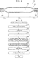
- FIG. 6 description is given of an internal pressure 202 of the intermediate 200 and a pressure 204 on the molten resin in the cavity 40 in the process from the injection of the molten resin into the mold 11 to the curing of the molten resin.
- the internal pressure 202 and the pressure 204 in FIG. 6 are schematic representations of an actual internal pressure of the intermediate 200 and an actual pressure on the molten resin for description of a tendency of pressure changes.
- An internal pressure P1 is applied in advance to the intermediate 200 arranged in the mold 11.
- the pressure P1 is applied to maintain the shape of the intermediate 200, and is, for example, 0.7 MPa.
- the molten resin is introduced so that a pressure on the molten resin passing through the cavity 40 is equal to a pressure in the cavity 40 before the molten resin flows into the cavity 40 (0.0 MPa in FIG. 6 ) as shown in a period up to a timing T1.
- the pistons 70 are not moved from the lower limit positions.
- the control device 80 controls the servomotors 74 to raise the pistons 70, thereby pressing the molten resin stored in the storage spaces 62, 64, and 65. As a result, the molten resin flows into the cavity 40.
- the internal pressure 202 of the intermediate 200 and the pressure 204 on the molten resin in the cavity 40 do not change as shown in a period from the timing T1 to a timing T2. In the period up to the timing T2, a pressure difference between the internal pressure 202 of the intermediate 200 and the pressure 204 on the molten resin in the cavity 40 is maintained to be a pressure difference D1.
- control device 80 controls the servomotors 74 to keep the servomotors 74 at a torque N1 and keep the upper limit of the ascending speed of each piston 70 at a speed VI.
- control device 80 maintains a constant force for pressing the molten resin, and determines the upper limit of the flow rate of the molten resin flowing into the cavity 40 per unit time.
- the pressure 204 on the molten resin in the cavity 40 is increased to a pressure P2 and the internal pressure 202 of the intermediate 200 is increased from the pressure P1 to a pressure P3 as shown in a period from the timing T2 to a timing T3.
- the control device 80 gradually increases the torque of the servomotors 74 from the torque N1.
- the control device 80 gradually increases the torque of the servomotors 74 from the torque N1 at intervals of 0.1 seconds to reach a torque N2 in 15 seconds.
- the torque N2 is a torque for bringing the pressure 204 on the molten resin in the cavity 40 to the pressure P2.
- the torque is constantly increased every 0.1 seconds. As a result, the control device 80 gradually increases the pressing force applied to the molten resin in the cavity 40.
- control device 80 keeps the upper limit of the ascending speed of each piston 70 at a speed V2 lower than the speed VI. As a result, the control device 80 determines the upper limit of the flow rate of the molten resin flowing into the cavity 40 per unit time.
- the pressure on the molten resin abruptly increases when the cavity 40 is filled with the molten resin and the impregnation is started.
- a pressure difference D2 between the internal pressure 202 of the intermediate 200 and the pressure 204 on the molten resin in the cavity 40 in the pressure increasing step is kept equal to or higher than the pressure difference D1.
- the pressure difference D2 is suppressed to be 2.0 MPa or lower.
- the pressure 204 on the molten resin in the cavity 40 is kept at the pressure P2 and the internal pressure 202 of the intermediate 200 is kept at the pressure P3 as shown in a period from the timing T3 to a timing T4.
- the control device 80 keeps the torque of the servomotors 74 at the torque N2. As a result, the pressing force applied to the molten resin in the cavity 40 is maintained.
- a pressure difference D3 between the internal pressure 202 of the intermediate 200 and the pressure 204 on the molten resin in the cavity 40 in the pressure maintaining step is kept equal to or higher than the pressure difference D1 and equal to or lower than 2.0 MPa.
- the resin is cured and the pressure 204 is reduced.
- the control device 80 lowers the pistons 70.
- the internal pressure of the intermediate 200 arranged in the cavity 40 is increased while the pressure on the molten resin is increased.
- the initial internal pressure of the intermediate 200 need not be preset high. As a result, it is possible to reduce the occurrence of a case where the liner 102 is deformed and the fiber bundle 104 is misaligned due to the internal pressure.
- By increasing the internal pressure of the intermediate 200 when the pressure on the molten resin is increased it is possible to suppress the deformation of the intermediate 200 due to the increase in the pressure on the molten resin.
- the pressure on the molten resin By controlling the pressure on the molten resin when the pressure on the molten resin is increased, the balance between the internal pressure of the intermediate 200 and the pressure on the molten resin in the cavity 40 can be maintained. As a result, it is possible to reduce the occurrence of a case where the liner 102 is deformed and the fiber bundle 104 is misaligned, and to suppress the deformation of the intermediate 200.
- the control device 80 controls the torque and the ascending speed of the servomotors 74 to control the force for pressing the molten resin and the flow rate of the molten resin flowing into the cavity 40 per unit time. As a result, the pressure on the molten resin flowing into the cavity 40 can be increased in association with the internal pressure of the intermediate 200.
- the control device 80 increases the torque of the servomotors 74 in units of 0.1 seconds.
- the control device 80 determines the upper limit of the ascending speed of the servomotors 74.
- the pressure 204 on the molten resin changes significantly in the initial stage of the period from the timing T2 to the timing T3.
- the degree of change in the pressure on the molten resin is greater than the change represented by the pressure 204.
- the fiber bundle 104 needs to be impregnated with the molten resin before the molten resin starts to cure. Therefore, the period of the increase in the pressure on the molten resin is predetermined based on a curing rate of the molten resin.
- the pressure on the molten resin to be held for the impregnation that is, the torque of the servomotors 74 to be increased is predetermined as well.
- the torque of the servomotors 74 is increased in units of time longer than 0.1 seconds (for example, in units of 1.0 second), a larger amount of torque is increased per unit time. That is, the amount of change in the torque per unit time increases.
- the molten resin injected into the mold 11 from the injection port 66 is temporarily stored in the storage spaces 62, 64, and 65 and then fills the cavity 40.
- the pressure on the molten resin in the cavity can be controlled more easily than a case where the molten resin from the injection port 66 directly fills the cavity 40.
- the molten resin in the storage spaces 62, 64, and 65 is pushed out by the pistons 70 moved by the servomotors 74 to fill the cavity 40.
- the pressure on the molten resin in the cavity 40 can appropriately be controlled by finely controlling the movement of the pistons 70 by the servomotors 74.
- the control device 80 controls the valve device 56 together with the servomotors 74 based on a computer program. Specifically, the control device 80 opens the valve device 56 at the timing T2, and closes the valve device 56 at the timing T3. During the period from the timing T2 to the timing T3, the control device 80 keeps a constant opening degree of the valve device 56. In the period after the timing T3, the control device 80 closes the valve device 56. In a modified example, the control device 80 may change the opening degree of the valve device 56 depending on the pressure on the molten resin during the period from the timing T2 to the timing T3.
- control device 80 may control the opening and closing of the valve device 56 without controlling the force for pressing the molten resin and the flow rate of the molten resin flowing into the cavity 40 per unit time.
Landscapes
- Engineering & Computer Science (AREA)
- Mechanical Engineering (AREA)
- Chemical & Material Sciences (AREA)
- Composite Materials (AREA)
- General Engineering & Computer Science (AREA)
- Manufacturing & Machinery (AREA)
- Injection Moulding Of Plastics Or The Like (AREA)
- Moulding By Coating Moulds (AREA)
- Casting Or Compression Moulding Of Plastics Or The Like (AREA)
- Pressure Vessels And Lids Thereof (AREA)
- Filling Or Discharging Of Gas Storage Vessels (AREA)
Applications Claiming Priority (1)
| Application Number | Priority Date | Filing Date | Title |
|---|---|---|---|
| JP2021042902A JP7447851B2 (ja) | 2021-03-16 | 2021-03-16 | 高圧タンクの製造方法、高圧タンク製造装置、及びコンピュータプログラム |
Publications (2)
| Publication Number | Publication Date |
|---|---|
| EP4059701A1 true EP4059701A1 (fr) | 2022-09-21 |
| EP4059701B1 EP4059701B1 (fr) | 2023-04-12 |
Family
ID=80775107
Family Applications (1)
| Application Number | Title | Priority Date | Filing Date |
|---|---|---|---|
| EP22161637.8A Active EP4059701B1 (fr) | 2021-03-16 | 2022-03-11 | Appareil de fabrication d'un réservoir haute pression |
Country Status (5)
| Country | Link |
|---|---|
| US (1) | US12173846B2 (fr) |
| EP (1) | EP4059701B1 (fr) |
| JP (1) | JP7447851B2 (fr) |
| KR (1) | KR20220129474A (fr) |
| CN (1) | CN115071169B (fr) |
Cited By (1)
| Publication number | Priority date | Publication date | Assignee | Title |
|---|---|---|---|---|
| US12036753B2 (en) | 2021-08-26 | 2024-07-16 | Toyota Jidosha Kabushiki Kaisha | Method for manufacturing tank and manufacturing device thereof |
Families Citing this family (1)
| Publication number | Priority date | Publication date | Assignee | Title |
|---|---|---|---|---|
| CN117698166B (zh) * | 2024-01-15 | 2026-04-24 | 北京航空航天大学 | 一种基于熔融树脂基体的热粘性介质隔膜成型工艺 |
Citations (5)
| Publication number | Priority date | Publication date | Assignee | Title |
|---|---|---|---|---|
| JP2019152310A (ja) | 2018-03-06 | 2019-09-12 | トヨタ自動車株式会社 | 高圧タンクの製造方法 |
| WO2020120895A1 (fr) * | 2018-12-14 | 2020-06-18 | Safran | Moule de cuisson pour fabriquer une piece de turbomachine en materiau composite a partir d'une preforme et procede de fabrication d'une piece au moyen d'un tel moule |
| WO2020166265A1 (fr) * | 2019-02-13 | 2020-08-20 | 株式会社豊田自動織機 | Procédé de production de récipient sous pression et dispositif de production de récipient sous pression |
| EP3702155A1 (fr) * | 2019-02-26 | 2020-09-02 | Fiberneering Technology Development B.V. | Procédé de préparation d'un produit composite |
| FR3094260A1 (fr) * | 2019-03-29 | 2020-10-02 | Faurecia Systemes D'echappement | Fabrication d’un réservoir à gaz sous haute pression |
Family Cites Families (33)
| Publication number | Priority date | Publication date | Assignee | Title |
|---|---|---|---|---|
| US5499739A (en) * | 1994-01-19 | 1996-03-19 | Atlantic Research Corporation | Thermoplastic liner for and method of overwrapping high pressure vessels |
| JPH0996399A (ja) * | 1995-07-25 | 1997-04-08 | Toyoda Gosei Co Ltd | 圧力容器 |
| CA2318005A1 (fr) * | 2000-09-12 | 2002-03-12 | Heinz Portmann | Conteneur haute pression precontraint renforce de fibres |
| US6651659B2 (en) * | 2001-05-23 | 2003-11-25 | John I. Izuchukwu | Ambulatory storage system for pressurized gases |
| US7100262B2 (en) * | 2003-07-08 | 2006-09-05 | Polymer & Steel Technologies Holding Company Llc | Method of forming filament-reinforced composite thermoplastic pressure vessel fitting assembly |
| US20070065538A1 (en) * | 2005-09-16 | 2007-03-22 | Husky Injection Molding Systems Ltd. | Molding system having valve including pump |
| CN100463129C (zh) | 2006-02-09 | 2009-02-18 | 夏普株式会社 | 半导体装置的制造方法及半导体装置的制造装置 |
| JP2007243146A (ja) | 2006-02-09 | 2007-09-20 | Sharp Corp | 半導体装置の製造方法、および、半導体装置の製造装置 |
| DE102006026609A1 (de) * | 2006-06-08 | 2008-01-17 | Krauss Maffei Gmbh | Komponentenzufuhr-Düse mit Druckentlastung |
| JP4552159B2 (ja) * | 2008-07-09 | 2010-09-29 | トヨタ自動車株式会社 | ガスタンク及びガスタンクの製造方法 |
| JP2010064392A (ja) | 2008-09-11 | 2010-03-25 | Toyota Motor Corp | 繊維強化プラスチックの製造方法および製造装置 |
| JP2010071444A (ja) * | 2008-09-22 | 2010-04-02 | Toyota Motor Corp | 高圧タンクおよびその製造方法、製造装置 |
| WO2010116526A1 (fr) * | 2009-04-10 | 2010-10-14 | トヨタ自動車株式会社 | Réservoir et procédé de fabrication associé |
| JP5456889B2 (ja) * | 2010-05-19 | 2014-04-02 | 八千代工業株式会社 | 圧力容器の口金部材とブローピンとの係合構造並びにこれを有する圧力容器の口金構造および圧力容器の製造方法 |
| WO2013109928A1 (fr) * | 2012-01-20 | 2013-07-25 | Lightsail Energy Inc. | Unité de stockage de gaz comprimé |
| DE102012013937A1 (de) * | 2012-07-16 | 2014-01-16 | Elkamet Kunststofftechnik Gmbh | Druckbehälter und Verfahren zur Herstellung dieses Behälters |
| KR20150121730A (ko) * | 2014-03-26 | 2015-10-30 | 현대자동차주식회사 | 연료가스 저장탱크 및 제조방법 |
| DE102014008649A1 (de) | 2014-06-13 | 2015-12-17 | Hydac Technology Gmbh | Verfahren zum Herstellen eines Druckbehälters |
| EP3012507B1 (fr) * | 2014-10-23 | 2019-02-06 | Magna Steyr Fuel Systems GesmbH | Procédé et outil destinés à la fabrication d'un récipient sous pression et récipient sous pression |
| KR102408678B1 (ko) * | 2014-11-28 | 2022-06-14 | 미쯔비시 가스 케미칼 컴파니, 인코포레이티드 | 압력용기, 라이너 및 압력용기의 제조방법 |
| JP2017096334A (ja) | 2015-11-19 | 2017-06-01 | トヨタ自動車株式会社 | 高圧タンクの製造方法 |
| DE102017101627A1 (de) * | 2016-02-18 | 2017-08-24 | Toyota Jidosha Kabushiki Kaisha | Hochdrucktank und Verfahren zum Herstellen eines Hochdrucktanks |
| US20170276294A1 (en) * | 2016-03-23 | 2017-09-28 | Worthington Industries, Inc. | Boss and liner interface for a pressure vessel |
| CN109790377B (zh) * | 2016-10-05 | 2022-02-25 | 法国全耐塑料新能源公司 | 具有单层衬里的复合材料压力容器 |
| JP6601425B2 (ja) * | 2017-01-18 | 2019-11-06 | トヨタ自動車株式会社 | ガスタンク用のライナーおよびガスタンク |
| JP6614180B2 (ja) * | 2017-02-21 | 2019-12-04 | トヨタ自動車株式会社 | 水素タンク素体の製造方法、および水素タンクの製造方法 |
| US10422477B2 (en) * | 2017-04-07 | 2019-09-24 | United Technologies Corporation | Composite vessel assembly and method of manufacture |
| JP6790997B2 (ja) | 2017-04-28 | 2020-11-25 | トヨタ自動車株式会社 | 高圧タンクの製造方法 |
| EP3489001B1 (fr) * | 2017-11-22 | 2025-08-06 | Afros S.P.A. | Appareil permettant un ajustement fin et contrôlé d'un processus de moulage par injection et procédé industriel associé |
| JP6939525B2 (ja) * | 2017-12-25 | 2021-09-22 | トヨタ自動車株式会社 | 高圧タンクの製造方法 |
| JP6915564B2 (ja) | 2018-02-21 | 2021-08-04 | トヨタ自動車株式会社 | 高圧タンクの製造方法 |
| JP2020175564A (ja) | 2019-04-17 | 2020-10-29 | トヨタ自動車株式会社 | 高圧タンクの製造方法 |
| JP7264075B2 (ja) * | 2020-01-30 | 2023-04-25 | トヨタ自動車株式会社 | 高圧タンク製造装置 |
-
2021
- 2021-03-16 JP JP2021042902A patent/JP7447851B2/ja active Active
-
2022
- 2022-03-11 KR KR1020220030471A patent/KR20220129474A/ko not_active Ceased
- 2022-03-11 EP EP22161637.8A patent/EP4059701B1/fr active Active
- 2022-03-14 US US17/654,809 patent/US12173846B2/en active Active
- 2022-03-14 CN CN202210246715.XA patent/CN115071169B/zh active Active
Patent Citations (5)
| Publication number | Priority date | Publication date | Assignee | Title |
|---|---|---|---|---|
| JP2019152310A (ja) | 2018-03-06 | 2019-09-12 | トヨタ自動車株式会社 | 高圧タンクの製造方法 |
| WO2020120895A1 (fr) * | 2018-12-14 | 2020-06-18 | Safran | Moule de cuisson pour fabriquer une piece de turbomachine en materiau composite a partir d'une preforme et procede de fabrication d'une piece au moyen d'un tel moule |
| WO2020166265A1 (fr) * | 2019-02-13 | 2020-08-20 | 株式会社豊田自動織機 | Procédé de production de récipient sous pression et dispositif de production de récipient sous pression |
| EP3702155A1 (fr) * | 2019-02-26 | 2020-09-02 | Fiberneering Technology Development B.V. | Procédé de préparation d'un produit composite |
| FR3094260A1 (fr) * | 2019-03-29 | 2020-10-02 | Faurecia Systemes D'echappement | Fabrication d’un réservoir à gaz sous haute pression |
Cited By (1)
| Publication number | Priority date | Publication date | Assignee | Title |
|---|---|---|---|---|
| US12036753B2 (en) | 2021-08-26 | 2024-07-16 | Toyota Jidosha Kabushiki Kaisha | Method for manufacturing tank and manufacturing device thereof |
Also Published As
| Publication number | Publication date |
|---|---|
| BR102022004425A2 (pt) | 2022-09-20 |
| KR20220129474A (ko) | 2022-09-23 |
| CN115071169B (zh) | 2024-05-31 |
| JP7447851B2 (ja) | 2024-03-12 |
| JP2022142647A (ja) | 2022-09-30 |
| US12173846B2 (en) | 2024-12-24 |
| CN115071169A (zh) | 2022-09-20 |
| EP4059701B1 (fr) | 2023-04-12 |
| US20220299161A1 (en) | 2022-09-22 |
Similar Documents
| Publication | Publication Date | Title |
|---|---|---|
| EP4059701A1 (fr) | Procédé de fabrication d'un réservoir haute pression, appareil de fabrication d'un réservoir haute pression, et support de stockage non transitoire | |
| KR102403410B1 (ko) | 섬유 강화 수지 성형품의 제조 방법 및 제조 장치 | |
| JP4825899B2 (ja) | 繊維強化樹脂の製造方法、繊維強化樹脂の製造装置 | |
| JP7287324B2 (ja) | 繊維強化樹脂成形品の製造方法および製造装置 | |
| JP7230832B2 (ja) | 繊維強化樹脂成形品の製造方法および製造装置 | |
| CN108372640A (zh) | 用于成型机的双板式合模单元 | |
| CN114101621A (zh) | 压铸机增压闭环控制系统 | |
| JP2014156115A (ja) | 繊維強化樹脂の製造方法 | |
| JP2010064392A (ja) | 繊維強化プラスチックの製造方法および製造装置 | |
| CN110382214B (zh) | 用于制造纤维增强塑料构件的方法和设备 | |
| BR102022004425B1 (pt) | Aparelho de fabricação de tanque de alta pressão | |
| KR100697631B1 (ko) | 섬유강화 열경화성 수지의 가변 단면 제품 제조방법 및 그장치 | |
| JP2007007910A (ja) | RTM(ResinTransferMolding)成形方法およびRTM成形用樹脂注入装置 | |
| JP7683573B2 (ja) | 高圧タンク用金型構造 | |
| JP7816028B2 (ja) | 高圧タンク及び高圧タンクの製造装置 | |
| JP7533287B2 (ja) | 高圧タンク製造装置及び高圧タンク製造方法 | |
| DE102017219719A1 (de) | Formwerkzeug und Verfahren zur Herstellung eines RTM-Bauteils | |
| JP2007062150A (ja) | 強化繊維プリフォームおよびrtm成形方法 | |
| JP2025073267A (ja) | タンクの製造方法、および、水素タンク | |
| KR101510457B1 (ko) | 전기 유압 액츄에이터를 활용한 서보 프레스 |
Legal Events
| Date | Code | Title | Description |
|---|---|---|---|
| PUAI | Public reference made under article 153(3) epc to a published international application that has entered the european phase |
Free format text: ORIGINAL CODE: 0009012 |
|
| STAA | Information on the status of an ep patent application or granted ep patent |
Free format text: STATUS: REQUEST FOR EXAMINATION WAS MADE |
|
| 17P | Request for examination filed |
Effective date: 20220311 |
|
| AK | Designated contracting states |
Kind code of ref document: A1 Designated state(s): AL AT BE BG CH CY CZ DE DK EE ES FI FR GB GR HR HU IE IS IT LI LT LU LV MC MK MT NL NO PL PT RO RS SE SI SK SM TR |
|
| GRAP | Despatch of communication of intention to grant a patent |
Free format text: ORIGINAL CODE: EPIDOSNIGR1 |
|
| STAA | Information on the status of an ep patent application or granted ep patent |
Free format text: STATUS: GRANT OF PATENT IS INTENDED |
|
| RIC1 | Information provided on ipc code assigned before grant |
Ipc: B29L 31/00 20060101ALN20221121BHEP Ipc: F17C 1/16 20060101ALI20221121BHEP Ipc: F17C 1/06 20060101ALI20221121BHEP Ipc: B29C 70/46 20060101ALI20221121BHEP Ipc: B29C 70/54 20060101ALI20221121BHEP Ipc: B29C 70/48 20060101AFI20221121BHEP |
|
| INTG | Intention to grant announced |
Effective date: 20221223 |
|
| RAP3 | Party data changed (applicant data changed or rights of an application transferred) |
Owner name: TOYOTA JIDOSHA KABUSHIKI KAISHA |
|
| RIN1 | Information on inventor provided before grant (corrected) |
Inventor name: NISHIYAMA, TOMOHIKO |
|
| GRAS | Grant fee paid |
Free format text: ORIGINAL CODE: EPIDOSNIGR3 |
|
| GRAA | (expected) grant |
Free format text: ORIGINAL CODE: 0009210 |
|
| STAA | Information on the status of an ep patent application or granted ep patent |
Free format text: STATUS: THE PATENT HAS BEEN GRANTED |
|
| AK | Designated contracting states |
Kind code of ref document: B1 Designated state(s): AL AT BE BG CH CY CZ DE DK EE ES FI FR GB GR HR HU IE IS IT LI LT LU LV MC MK MT NL NO PL PT RO RS SE SI SK SM TR |
|
| REG | Reference to a national code |
Ref country code: GB Ref legal event code: FG4D |
|
| REG | Reference to a national code |
Ref country code: CH Ref legal event code: EP |
|
| REG | Reference to a national code |
Ref country code: DE Ref legal event code: R096 Ref document number: 602022000032 Country of ref document: DE |
|
| REG | Reference to a national code |
Ref country code: IE Ref legal event code: FG4D |
|
| REG | Reference to a national code |
Ref country code: AT Ref legal event code: REF Ref document number: 1559536 Country of ref document: AT Kind code of ref document: T Effective date: 20230515 |
|
| REG | Reference to a national code |
Ref country code: LT Ref legal event code: MG9D |
|
| REG | Reference to a national code |
Ref country code: NL Ref legal event code: MP Effective date: 20230412 |
|
| REG | Reference to a national code |
Ref country code: DE Ref legal event code: R084 Ref document number: 602022000032 Country of ref document: DE |
|
| REG | Reference to a national code |
Ref country code: AT Ref legal event code: MK05 Ref document number: 1559536 Country of ref document: AT Kind code of ref document: T Effective date: 20230412 |
|
| PG25 | Lapsed in a contracting state [announced via postgrant information from national office to epo] |
Ref country code: NL Free format text: LAPSE BECAUSE OF FAILURE TO SUBMIT A TRANSLATION OF THE DESCRIPTION OR TO PAY THE FEE WITHIN THE PRESCRIBED TIME-LIMIT Effective date: 20230412 |
|
| PG25 | Lapsed in a contracting state [announced via postgrant information from national office to epo] |
Ref country code: SE Free format text: LAPSE BECAUSE OF FAILURE TO SUBMIT A TRANSLATION OF THE DESCRIPTION OR TO PAY THE FEE WITHIN THE PRESCRIBED TIME-LIMIT Effective date: 20230412 Ref country code: PT Free format text: LAPSE BECAUSE OF FAILURE TO SUBMIT A TRANSLATION OF THE DESCRIPTION OR TO PAY THE FEE WITHIN THE PRESCRIBED TIME-LIMIT Effective date: 20230814 Ref country code: NO Free format text: LAPSE BECAUSE OF FAILURE TO SUBMIT A TRANSLATION OF THE DESCRIPTION OR TO PAY THE FEE WITHIN THE PRESCRIBED TIME-LIMIT Effective date: 20230712 Ref country code: ES Free format text: LAPSE BECAUSE OF FAILURE TO SUBMIT A TRANSLATION OF THE DESCRIPTION OR TO PAY THE FEE WITHIN THE PRESCRIBED TIME-LIMIT Effective date: 20230412 Ref country code: AT Free format text: LAPSE BECAUSE OF FAILURE TO SUBMIT A TRANSLATION OF THE DESCRIPTION OR TO PAY THE FEE WITHIN THE PRESCRIBED TIME-LIMIT Effective date: 20230412 |
|
| P01 | Opt-out of the competence of the unified patent court (upc) registered |
Effective date: 20231024 |
|
| PG25 | Lapsed in a contracting state [announced via postgrant information from national office to epo] |
Ref country code: RS Free format text: LAPSE BECAUSE OF FAILURE TO SUBMIT A TRANSLATION OF THE DESCRIPTION OR TO PAY THE FEE WITHIN THE PRESCRIBED TIME-LIMIT Effective date: 20230412 Ref country code: PL Free format text: LAPSE BECAUSE OF FAILURE TO SUBMIT A TRANSLATION OF THE DESCRIPTION OR TO PAY THE FEE WITHIN THE PRESCRIBED TIME-LIMIT Effective date: 20230412 Ref country code: LV Free format text: LAPSE BECAUSE OF FAILURE TO SUBMIT A TRANSLATION OF THE DESCRIPTION OR TO PAY THE FEE WITHIN THE PRESCRIBED TIME-LIMIT Effective date: 20230412 Ref country code: LT Free format text: LAPSE BECAUSE OF FAILURE TO SUBMIT A TRANSLATION OF THE DESCRIPTION OR TO PAY THE FEE WITHIN THE PRESCRIBED TIME-LIMIT Effective date: 20230412 Ref country code: IS Free format text: LAPSE BECAUSE OF FAILURE TO SUBMIT A TRANSLATION OF THE DESCRIPTION OR TO PAY THE FEE WITHIN THE PRESCRIBED TIME-LIMIT Effective date: 20230812 Ref country code: HR Free format text: LAPSE BECAUSE OF FAILURE TO SUBMIT A TRANSLATION OF THE DESCRIPTION OR TO PAY THE FEE WITHIN THE PRESCRIBED TIME-LIMIT Effective date: 20230412 Ref country code: GR Free format text: LAPSE BECAUSE OF FAILURE TO SUBMIT A TRANSLATION OF THE DESCRIPTION OR TO PAY THE FEE WITHIN THE PRESCRIBED TIME-LIMIT Effective date: 20230713 Ref country code: AL Free format text: LAPSE BECAUSE OF FAILURE TO SUBMIT A TRANSLATION OF THE DESCRIPTION OR TO PAY THE FEE WITHIN THE PRESCRIBED TIME-LIMIT Effective date: 20230412 |
|
| PG25 | Lapsed in a contracting state [announced via postgrant information from national office to epo] |
Ref country code: FI Free format text: LAPSE BECAUSE OF FAILURE TO SUBMIT A TRANSLATION OF THE DESCRIPTION OR TO PAY THE FEE WITHIN THE PRESCRIBED TIME-LIMIT Effective date: 20230412 |
|
| REG | Reference to a national code |
Ref country code: DE Ref legal event code: R097 Ref document number: 602022000032 Country of ref document: DE |
|
| PG25 | Lapsed in a contracting state [announced via postgrant information from national office to epo] |
Ref country code: SK Free format text: LAPSE BECAUSE OF FAILURE TO SUBMIT A TRANSLATION OF THE DESCRIPTION OR TO PAY THE FEE WITHIN THE PRESCRIBED TIME-LIMIT Effective date: 20230412 |
|
| PG25 | Lapsed in a contracting state [announced via postgrant information from national office to epo] |
Ref country code: SM Free format text: LAPSE BECAUSE OF FAILURE TO SUBMIT A TRANSLATION OF THE DESCRIPTION OR TO PAY THE FEE WITHIN THE PRESCRIBED TIME-LIMIT Effective date: 20230412 Ref country code: SK Free format text: LAPSE BECAUSE OF FAILURE TO SUBMIT A TRANSLATION OF THE DESCRIPTION OR TO PAY THE FEE WITHIN THE PRESCRIBED TIME-LIMIT Effective date: 20230412 Ref country code: RO Free format text: LAPSE BECAUSE OF FAILURE TO SUBMIT A TRANSLATION OF THE DESCRIPTION OR TO PAY THE FEE WITHIN THE PRESCRIBED TIME-LIMIT Effective date: 20230412 Ref country code: EE Free format text: LAPSE BECAUSE OF FAILURE TO SUBMIT A TRANSLATION OF THE DESCRIPTION OR TO PAY THE FEE WITHIN THE PRESCRIBED TIME-LIMIT Effective date: 20230412 Ref country code: DK Free format text: LAPSE BECAUSE OF FAILURE TO SUBMIT A TRANSLATION OF THE DESCRIPTION OR TO PAY THE FEE WITHIN THE PRESCRIBED TIME-LIMIT Effective date: 20230412 Ref country code: CZ Free format text: LAPSE BECAUSE OF FAILURE TO SUBMIT A TRANSLATION OF THE DESCRIPTION OR TO PAY THE FEE WITHIN THE PRESCRIBED TIME-LIMIT Effective date: 20230412 |
|
| PLBE | No opposition filed within time limit |
Free format text: ORIGINAL CODE: 0009261 |
|
| STAA | Information on the status of an ep patent application or granted ep patent |
Free format text: STATUS: NO OPPOSITION FILED WITHIN TIME LIMIT |
|
| 26N | No opposition filed |
Effective date: 20240115 |
|
| PG25 | Lapsed in a contracting state [announced via postgrant information from national office to epo] |
Ref country code: SI Free format text: LAPSE BECAUSE OF FAILURE TO SUBMIT A TRANSLATION OF THE DESCRIPTION OR TO PAY THE FEE WITHIN THE PRESCRIBED TIME-LIMIT Effective date: 20230412 |
|
| PG25 | Lapsed in a contracting state [announced via postgrant information from national office to epo] |
Ref country code: SI Free format text: LAPSE BECAUSE OF FAILURE TO SUBMIT A TRANSLATION OF THE DESCRIPTION OR TO PAY THE FEE WITHIN THE PRESCRIBED TIME-LIMIT Effective date: 20230412 Ref country code: IT Free format text: LAPSE BECAUSE OF FAILURE TO SUBMIT A TRANSLATION OF THE DESCRIPTION OR TO PAY THE FEE WITHIN THE PRESCRIBED TIME-LIMIT Effective date: 20230412 |
|
| PG25 | Lapsed in a contracting state [announced via postgrant information from national office to epo] |
Ref country code: BG Free format text: LAPSE BECAUSE OF FAILURE TO SUBMIT A TRANSLATION OF THE DESCRIPTION OR TO PAY THE FEE WITHIN THE PRESCRIBED TIME-LIMIT Effective date: 20230412 |
|
| PG25 | Lapsed in a contracting state [announced via postgrant information from national office to epo] |
Ref country code: LU Free format text: LAPSE BECAUSE OF NON-PAYMENT OF DUE FEES Effective date: 20240311 |
|
| PG25 | Lapsed in a contracting state [announced via postgrant information from national office to epo] |
Ref country code: MC Free format text: LAPSE BECAUSE OF FAILURE TO SUBMIT A TRANSLATION OF THE DESCRIPTION OR TO PAY THE FEE WITHIN THE PRESCRIBED TIME-LIMIT Effective date: 20230412 |
|
| PG25 | Lapsed in a contracting state [announced via postgrant information from national office to epo] |
Ref country code: MC Free format text: LAPSE BECAUSE OF FAILURE TO SUBMIT A TRANSLATION OF THE DESCRIPTION OR TO PAY THE FEE WITHIN THE PRESCRIBED TIME-LIMIT Effective date: 20230412 Ref country code: LU Free format text: LAPSE BECAUSE OF NON-PAYMENT OF DUE FEES Effective date: 20240311 Ref country code: BG Free format text: LAPSE BECAUSE OF FAILURE TO SUBMIT A TRANSLATION OF THE DESCRIPTION OR TO PAY THE FEE WITHIN THE PRESCRIBED TIME-LIMIT Effective date: 20230412 |
|
| REG | Reference to a national code |
Ref country code: BE Ref legal event code: MM Effective date: 20240331 |
|
| PG25 | Lapsed in a contracting state [announced via postgrant information from national office to epo] |
Ref country code: BE Free format text: LAPSE BECAUSE OF NON-PAYMENT OF DUE FEES Effective date: 20240331 |
|
| PG25 | Lapsed in a contracting state [announced via postgrant information from national office to epo] |
Ref country code: FR Free format text: LAPSE BECAUSE OF NON-PAYMENT OF DUE FEES Effective date: 20240331 |
|
| PG25 | Lapsed in a contracting state [announced via postgrant information from national office to epo] |
Ref country code: IE Free format text: LAPSE BECAUSE OF NON-PAYMENT OF DUE FEES Effective date: 20240311 |
|
| PG25 | Lapsed in a contracting state [announced via postgrant information from national office to epo] |
Ref country code: IE Free format text: LAPSE BECAUSE OF NON-PAYMENT OF DUE FEES Effective date: 20240311 Ref country code: FR Free format text: LAPSE BECAUSE OF NON-PAYMENT OF DUE FEES Effective date: 20240331 Ref country code: BE Free format text: LAPSE BECAUSE OF NON-PAYMENT OF DUE FEES Effective date: 20240331 |
|
| PG25 | Lapsed in a contracting state [announced via postgrant information from national office to epo] |
Ref country code: CY Free format text: LAPSE BECAUSE OF FAILURE TO SUBMIT A TRANSLATION OF THE DESCRIPTION OR TO PAY THE FEE WITHIN THE PRESCRIBED TIME-LIMIT; INVALID AB INITIO Effective date: 20220311 |
|
| REG | Reference to a national code |
Ref country code: CH Ref legal event code: H13 Free format text: ST27 STATUS EVENT CODE: U-0-0-H10-H13 (AS PROVIDED BY THE NATIONAL OFFICE) Effective date: 20251023 |
|
| PG25 | Lapsed in a contracting state [announced via postgrant information from national office to epo] |
Ref country code: TR Free format text: LAPSE BECAUSE OF FAILURE TO SUBMIT A TRANSLATION OF THE DESCRIPTION OR TO PAY THE FEE WITHIN THE PRESCRIBED TIME-LIMIT Effective date: 20230412 |
|
| PG25 | Lapsed in a contracting state [announced via postgrant information from national office to epo] |
Ref country code: CH Free format text: LAPSE BECAUSE OF NON-PAYMENT OF DUE FEES Effective date: 20250331 |
|
| PGFP | Annual fee paid to national office [announced via postgrant information from national office to epo] |
Ref country code: DE Payment date: 20260128 Year of fee payment: 5 |