EP4059767A1 - Connecteur de chargement pour véhicule électrique - Google Patents
Connecteur de chargement pour véhicule électrique Download PDFInfo
- Publication number
- EP4059767A1 EP4059767A1 EP21163123.9A EP21163123A EP4059767A1 EP 4059767 A1 EP4059767 A1 EP 4059767A1 EP 21163123 A EP21163123 A EP 21163123A EP 4059767 A1 EP4059767 A1 EP 4059767A1
- Authority
- EP
- European Patent Office
- Prior art keywords
- sensor
- charging connector
- casing
- charging
- connector
- Prior art date
- Legal status (The legal status is an assumption and is not a legal conclusion. Google has not performed a legal analysis and makes no representation as to the accuracy of the status listed.)
- Pending
Links
- 238000012545 processing Methods 0.000 claims description 11
- 238000007789 sealing Methods 0.000 claims description 10
- 230000003287 optical effect Effects 0.000 claims description 6
- 238000012546 transfer Methods 0.000 claims description 4
- 238000010586 diagram Methods 0.000 description 9
- 238000000034 method Methods 0.000 description 9
- 238000004891 communication Methods 0.000 description 6
- 238000013461 design Methods 0.000 description 4
- 230000001939 inductive effect Effects 0.000 description 4
- XLYOFNOQVPJJNP-UHFFFAOYSA-N water Substances O XLYOFNOQVPJJNP-UHFFFAOYSA-N 0.000 description 4
- 230000005540 biological transmission Effects 0.000 description 3
- 230000011664 signaling Effects 0.000 description 3
- XAGFODPZIPBFFR-UHFFFAOYSA-N aluminium Chemical compound [Al] XAGFODPZIPBFFR-UHFFFAOYSA-N 0.000 description 2
- 229910052782 aluminium Inorganic materials 0.000 description 2
- 230000001419 dependent effect Effects 0.000 description 2
- 230000007613 environmental effect Effects 0.000 description 2
- 238000009413 insulation Methods 0.000 description 2
- 239000000463 material Substances 0.000 description 2
- 230000008054 signal transmission Effects 0.000 description 2
- 239000003990 capacitor Substances 0.000 description 1
- 238000006243 chemical reaction Methods 0.000 description 1
- 238000010276 construction Methods 0.000 description 1
- 238000011109 contamination Methods 0.000 description 1
- 238000011157 data evaluation Methods 0.000 description 1
- 238000001514 detection method Methods 0.000 description 1
- 238000010292 electrical insulation Methods 0.000 description 1
- 238000011156 evaluation Methods 0.000 description 1
- 239000011888 foil Substances 0.000 description 1
- 230000006698 induction Effects 0.000 description 1
- 238000002955 isolation Methods 0.000 description 1
- 239000011347 resin Substances 0.000 description 1
- 229920005989 resin Polymers 0.000 description 1
- 239000000758 substrate Substances 0.000 description 1
- 230000002195 synergetic effect Effects 0.000 description 1
- 239000002966 varnish Substances 0.000 description 1
- 239000013585 weight reducing agent Substances 0.000 description 1
Images

Classifications
-
- B—PERFORMING OPERATIONS; TRANSPORTING
- B60—VEHICLES IN GENERAL
- B60L—PROPULSION OF ELECTRICALLY-PROPELLED VEHICLES; SUPPLYING ELECTRIC POWER FOR AUXILIARY EQUIPMENT OF ELECTRICALLY-PROPELLED VEHICLES; ELECTRODYNAMIC BRAKE SYSTEMS FOR VEHICLES IN GENERAL; MAGNETIC SUSPENSION OR LEVITATION FOR VEHICLES; MONITORING OPERATING VARIABLES OF ELECTRICALLY-PROPELLED VEHICLES; ELECTRIC SAFETY DEVICES FOR ELECTRICALLY-PROPELLED VEHICLES
- B60L53/00—Methods of charging batteries, specially adapted for electric vehicles; Charging stations or on-board charging equipment therefor; Exchange of energy storage elements in electric vehicles
- B60L53/10—Methods of charging batteries, specially adapted for electric vehicles; Charging stations or on-board charging equipment therefor; Exchange of energy storage elements in electric vehicles characterised by the energy transfer between the charging station and the vehicle
- B60L53/14—Conductive energy transfer
- B60L53/16—Connectors, e.g. plugs or sockets, specially adapted for charging electric vehicles
-
- B—PERFORMING OPERATIONS; TRANSPORTING
- B60—VEHICLES IN GENERAL
- B60L—PROPULSION OF ELECTRICALLY-PROPELLED VEHICLES; SUPPLYING ELECTRIC POWER FOR AUXILIARY EQUIPMENT OF ELECTRICALLY-PROPELLED VEHICLES; ELECTRODYNAMIC BRAKE SYSTEMS FOR VEHICLES IN GENERAL; MAGNETIC SUSPENSION OR LEVITATION FOR VEHICLES; MONITORING OPERATING VARIABLES OF ELECTRICALLY-PROPELLED VEHICLES; ELECTRIC SAFETY DEVICES FOR ELECTRICALLY-PROPELLED VEHICLES
- B60L53/00—Methods of charging batteries, specially adapted for electric vehicles; Charging stations or on-board charging equipment therefor; Exchange of energy storage elements in electric vehicles
- B60L53/10—Methods of charging batteries, specially adapted for electric vehicles; Charging stations or on-board charging equipment therefor; Exchange of energy storage elements in electric vehicles characterised by the energy transfer between the charging station and the vehicle
- B60L53/14—Conductive energy transfer
- B60L53/18—Cables specially adapted for charging electric vehicles
-
- B—PERFORMING OPERATIONS; TRANSPORTING
- B60—VEHICLES IN GENERAL
- B60L—PROPULSION OF ELECTRICALLY-PROPELLED VEHICLES; SUPPLYING ELECTRIC POWER FOR AUXILIARY EQUIPMENT OF ELECTRICALLY-PROPELLED VEHICLES; ELECTRODYNAMIC BRAKE SYSTEMS FOR VEHICLES IN GENERAL; MAGNETIC SUSPENSION OR LEVITATION FOR VEHICLES; MONITORING OPERATING VARIABLES OF ELECTRICALLY-PROPELLED VEHICLES; ELECTRIC SAFETY DEVICES FOR ELECTRICALLY-PROPELLED VEHICLES
- B60L53/00—Methods of charging batteries, specially adapted for electric vehicles; Charging stations or on-board charging equipment therefor; Exchange of energy storage elements in electric vehicles
- B60L53/30—Constructional details of charging stations
- B60L53/35—Means for automatic or assisted adjustment of the relative position of charging devices and vehicles
- B60L53/37—Means for automatic or assisted adjustment of the relative position of charging devices and vehicles using optical position determination, e.g. using cameras
-
- B—PERFORMING OPERATIONS; TRANSPORTING
- B60—VEHICLES IN GENERAL
- B60L—PROPULSION OF ELECTRICALLY-PROPELLED VEHICLES; SUPPLYING ELECTRIC POWER FOR AUXILIARY EQUIPMENT OF ELECTRICALLY-PROPELLED VEHICLES; ELECTRODYNAMIC BRAKE SYSTEMS FOR VEHICLES IN GENERAL; MAGNETIC SUSPENSION OR LEVITATION FOR VEHICLES; MONITORING OPERATING VARIABLES OF ELECTRICALLY-PROPELLED VEHICLES; ELECTRIC SAFETY DEVICES FOR ELECTRICALLY-PROPELLED VEHICLES
- B60L53/00—Methods of charging batteries, specially adapted for electric vehicles; Charging stations or on-board charging equipment therefor; Exchange of energy storage elements in electric vehicles
- B60L53/60—Monitoring or controlling charging stations
- B60L53/62—Monitoring or controlling charging stations in response to charging parameters, e.g. current, voltage or electrical charge
-
- H—ELECTRICITY
- H01—ELECTRIC ELEMENTS
- H01R—ELECTRICALLY-CONDUCTIVE CONNECTIONS; STRUCTURAL ASSOCIATIONS OF A PLURALITY OF MUTUALLY-INSULATED ELECTRICAL CONNECTING ELEMENTS; COUPLING DEVICES; CURRENT COLLECTORS
- H01R13/00—Details of coupling devices of the kinds covered by groups H01R12/70 or H01R24/00 - H01R33/00
- H01R13/46—Bases; Cases
- H01R13/502—Bases; Cases composed of different pieces
-
- H—ELECTRICITY
- H01—ELECTRIC ELEMENTS
- H01R—ELECTRICALLY-CONDUCTIVE CONNECTIONS; STRUCTURAL ASSOCIATIONS OF A PLURALITY OF MUTUALLY-INSULATED ELECTRICAL CONNECTING ELEMENTS; COUPLING DEVICES; CURRENT COLLECTORS
- H01R13/00—Details of coupling devices of the kinds covered by groups H01R12/70 or H01R24/00 - H01R33/00
- H01R13/62—Means for facilitating engagement or disengagement of coupling parts or for holding them in engagement
- H01R13/627—Snap or like fastening
- H01R13/6275—Latching arms not integral with the housing
-
- H—ELECTRICITY
- H01—ELECTRIC ELEMENTS
- H01R—ELECTRICALLY-CONDUCTIVE CONNECTIONS; STRUCTURAL ASSOCIATIONS OF A PLURALITY OF MUTUALLY-INSULATED ELECTRICAL CONNECTING ELEMENTS; COUPLING DEVICES; CURRENT COLLECTORS
- H01R13/00—Details of coupling devices of the kinds covered by groups H01R12/70 or H01R24/00 - H01R33/00
- H01R13/64—Means for preventing incorrect coupling
- H01R13/641—Means for preventing incorrect coupling by indicating incorrect coupling; by indicating correct or full engagement
-
- H—ELECTRICITY
- H01—ELECTRIC ELEMENTS
- H01R—ELECTRICALLY-CONDUCTIVE CONNECTIONS; STRUCTURAL ASSOCIATIONS OF A PLURALITY OF MUTUALLY-INSULATED ELECTRICAL CONNECTING ELEMENTS; COUPLING DEVICES; CURRENT COLLECTORS
- H01R13/00—Details of coupling devices of the kinds covered by groups H01R12/70 or H01R24/00 - H01R33/00
- H01R13/66—Structural association with built-in electrical component
- H01R13/665—Structural association with built-in electrical component with built-in electronic circuit
- H01R13/6683—Structural association with built-in electrical component with built-in electronic circuit with built-in sensor
-
- H—ELECTRICITY
- H01—ELECTRIC ELEMENTS
- H01R—ELECTRICALLY-CONDUCTIVE CONNECTIONS; STRUCTURAL ASSOCIATIONS OF A PLURALITY OF MUTUALLY-INSULATED ELECTRICAL CONNECTING ELEMENTS; COUPLING DEVICES; CURRENT COLLECTORS
- H01R13/00—Details of coupling devices of the kinds covered by groups H01R12/70 or H01R24/00 - H01R33/00
- H01R13/66—Structural association with built-in electrical component
- H01R13/665—Structural association with built-in electrical component with built-in electronic circuit
- H01R13/6691—Structural association with built-in electrical component with built-in electronic circuit with built-in signalling means
-
- G—PHYSICS
- G01—MEASURING; TESTING
- G01R—MEASURING ELECTRIC VARIABLES; MEASURING MAGNETIC VARIABLES
- G01R31/00—Arrangements for testing electric properties; Arrangements for locating electric faults; Arrangements for electrical testing characterised by what is being tested not provided for elsewhere
- G01R31/50—Testing of electric apparatus, lines, cables or components for short-circuits, continuity, leakage current or incorrect line connections
- G01R31/66—Testing of connections, e.g. of plugs or non-disconnectable joints
- G01R31/68—Testing of releasable connections, e.g. of terminals mounted on a printed circuit board
-
- H—ELECTRICITY
- H01—ELECTRIC ELEMENTS
- H01R—ELECTRICALLY-CONDUCTIVE CONNECTIONS; STRUCTURAL ASSOCIATIONS OF A PLURALITY OF MUTUALLY-INSULATED ELECTRICAL CONNECTING ELEMENTS; COUPLING DEVICES; CURRENT COLLECTORS
- H01R2201/00—Connectors or connections adapted for particular applications
- H01R2201/26—Connectors or connections adapted for particular applications for vehicles
-
- Y—GENERAL TAGGING OF NEW TECHNOLOGICAL DEVELOPMENTS; GENERAL TAGGING OF CROSS-SECTIONAL TECHNOLOGIES SPANNING OVER SEVERAL SECTIONS OF THE IPC; TECHNICAL SUBJECTS COVERED BY FORMER USPC CROSS-REFERENCE ART COLLECTIONS [XRACs] AND DIGESTS
- Y02—TECHNOLOGIES OR APPLICATIONS FOR MITIGATION OR ADAPTATION AGAINST CLIMATE CHANGE
- Y02T—CLIMATE CHANGE MITIGATION TECHNOLOGIES RELATED TO TRANSPORTATION
- Y02T10/00—Road transport of goods or passengers
- Y02T10/60—Other road transportation technologies with climate change mitigation effect
- Y02T10/70—Energy storage systems for electromobility, e.g. batteries
-
- Y—GENERAL TAGGING OF NEW TECHNOLOGICAL DEVELOPMENTS; GENERAL TAGGING OF CROSS-SECTIONAL TECHNOLOGIES SPANNING OVER SEVERAL SECTIONS OF THE IPC; TECHNICAL SUBJECTS COVERED BY FORMER USPC CROSS-REFERENCE ART COLLECTIONS [XRACs] AND DIGESTS
- Y02—TECHNOLOGIES OR APPLICATIONS FOR MITIGATION OR ADAPTATION AGAINST CLIMATE CHANGE
- Y02T—CLIMATE CHANGE MITIGATION TECHNOLOGIES RELATED TO TRANSPORTATION
- Y02T10/00—Road transport of goods or passengers
- Y02T10/60—Other road transportation technologies with climate change mitigation effect
- Y02T10/7072—Electromobility specific charging systems or methods for batteries, ultracapacitors, supercapacitors or double-layer capacitors
-
- Y—GENERAL TAGGING OF NEW TECHNOLOGICAL DEVELOPMENTS; GENERAL TAGGING OF CROSS-SECTIONAL TECHNOLOGIES SPANNING OVER SEVERAL SECTIONS OF THE IPC; TECHNICAL SUBJECTS COVERED BY FORMER USPC CROSS-REFERENCE ART COLLECTIONS [XRACs] AND DIGESTS
- Y02—TECHNOLOGIES OR APPLICATIONS FOR MITIGATION OR ADAPTATION AGAINST CLIMATE CHANGE
- Y02T—CLIMATE CHANGE MITIGATION TECHNOLOGIES RELATED TO TRANSPORTATION
- Y02T90/00—Enabling technologies or technologies with a potential or indirect contribution to GHG emissions mitigation
- Y02T90/10—Technologies relating to charging of electric vehicles
- Y02T90/12—Electric charging stations
-
- Y—GENERAL TAGGING OF NEW TECHNOLOGICAL DEVELOPMENTS; GENERAL TAGGING OF CROSS-SECTIONAL TECHNOLOGIES SPANNING OVER SEVERAL SECTIONS OF THE IPC; TECHNICAL SUBJECTS COVERED BY FORMER USPC CROSS-REFERENCE ART COLLECTIONS [XRACs] AND DIGESTS
- Y02—TECHNOLOGIES OR APPLICATIONS FOR MITIGATION OR ADAPTATION AGAINST CLIMATE CHANGE
- Y02T—CLIMATE CHANGE MITIGATION TECHNOLOGIES RELATED TO TRANSPORTATION
- Y02T90/00—Enabling technologies or technologies with a potential or indirect contribution to GHG emissions mitigation
- Y02T90/10—Technologies relating to charging of electric vehicles
- Y02T90/14—Plug-in electric vehicles
Definitions
- the present invention relates to a charging connector for an electric vehicle, a charging station, a sensor, and a use of a sensor. More specifically, the charging connector further comprises a sensor configured to indicate a safe fastening of the connector.
- a sensor that has an electrical connection for power supply and data or signal transmission.
- a sensor cable may be guided through the casing of the connector to a processing module and a power supply at the charging station and/or a processing module inside the connector casing.
- a casing that reduces the weight of the connector may increase the susceptibility of the connector and the sensor cable to the sensor to environmental conditions.
- An objective of the invention may be to provide an improved charging connector.
- the described embodiments similarly pertain to the charging connector for a vehicle, the charging station, the sensor, and the use of a sensor. Synergetic effects may arise from different combinations of the embodiments although they might not be described in detail.
- a charging connector for a vehicle comprises a latch configured to secure a mechanical connection of the charging connector to a vehicle-side socket.
- the charging connector further comprises a sensor configured to indicate the correct secured connection, i.e., a safe fastening of the charging connector to the vehicle.
- the charging connector further comprises a first casing being an external casing, and a second casing, the second casing being a closed inner casing. The first and the second casing enclose a charging connector interface to the vehicle socket, and the second casing encloses a charging cable.
- the sensor is arranged outside the second casing.
- the charging connector provides the charging current from a charging station to the battery of an electric vehicle.
- charging connector is understood to be a handheld device such as a charging gun or charging nozzle.
- the counterpart of the charging connector on vehicle-side is called “socket” in this disclosure.
- the socket has a counter-interface to the interface of the charging connector, and the interface comprises an electrical and a mechanical part.
- the latch is an arrangement, which is a part of the mechanical interface of the connector and is configured to secure the charging connector mechanically to the socket of a vehicle.
- the latch may have moving parts and/or parts that are elastic, or it may be movable itself and is configured such that the mechanical connection can be established and released.
- the charging connector may be a part of the charging station, under the terms “cable, current, signal to/from the charging station", is understood the cable, current, signal to/from the fixed part of the charging station. This fixed part is also designated “charging post” in this disclosure.
- the connector comprises a first casing, which is an outer casing and further a second casing, which is an inner casing. Between the external casing and the inner casing, there may be free space or air such that the weight of the connector is reduced, thereby providing a convenient handling and shape of the connector.
- the first casing may comprise channels to the environment to exchange heat via air and hence is in parts open to the environment, whereas the second, inner casing is tight and insulates its inner part from ambient conditions.
- the inner casing includes a charging cable and a connector interface to the vehicle socket.
- the second casing is an important part of the connector as it insulates the ambient influences such as dirt, moisture, water etc. from the high current parts in the area of the contacts.
- a further, third casing may insulate the contacts of the wires of the cable.
- the external casing therefore can be seen as a cover or a shell that may not be integral with the second casing.
- the charging connector comprises a sensor cable comprising a data wire and/or a power wire.
- the sensor cable is located at least partly inside the second casing configured to transmit data from and/or power to the sensor.
- the sensor cable may arranged such that it is guided from the fixed station to the charging connector, and together with the charging cable to the inside of the second casing.
- the sensor cable may include a data wire and/or a power supply wire and join the charging cable for charging the battery of the vehicle. This is achieved best at a location where the sheathing of the inner cables or wires ends. Such a location is inside the second casing.
- a sensor cable is defined here to be a cable for the transmission of signal or data from or to the sensor, and/or power to the sensor.
- the sensor cable or wire may end at the sensor or sensor electronics in case of a wired connection. In another case, it may end at a wireless interface so that it is not attached to the sensor or sensor electronics outside the inner casing as described in more detail below.
- Guiding the sensor cable into the inner casing has the advantage that both, sensor and charging cables can be guided together, and even be guided together up to the contactor area, thereby facilitating the guiding of the cables as one single cable instead of two separated cables, and especially without cutting the sheathing to lead out the sensor cable.
- the second casing comprises a sealing pass-through configured to guide the sensor cable from the inside of the second casing to the outside of the second casing.
- “Outside the second casing” means that it is guided to the sensor or sensor electronics at or near the sensor, inside the external casing. Since the insulation characteristics of the inner casing shall be maintained, the pass-through has to be realized in a sealing way such that the inner casing is still tight, protecting its inside from ambient conditions.
- the charging connector comprises a wireless interface configured to connect the sensor wirelessly to a processing circuit and / or a power supply.
- the processing circuit may be, for example, a PCB (printed circuit board) with a wireless communication module, A/D conversion capabilities, or capabilities for signal processing, data evaluation, etc.
- the processing circuit may be mounted inside the inner casing and may provide the counter-part of the wireless interface to the sensor-side wireless interface.
- the wireless interface is attached, for example, at the outside surface of the inner casing facing the wireless interface at the inside or being at least in the vicinity to it.
- the wireless interface may comprise, for example, NFC (near field communication) devices such as RFID (radiofrequency identification) antennas, Bluetooth or another means to transmit power and/or data wirelessly, for example, by using induction.
- the charging connector comprises a wireless interface configured to connect the sensor wirelessly to a processing circuit and / or a power supply external of the charging connector.
- the sensor may be connected wirelessly to the fixed part of the station.
- an electronic module near or at the sensor inside the external casing and outside the inner casing may comprise a re-chargeable power storage, such as a capacitor or a battery.
- the charging station may comprise a wireless interface for data and for power, for example an inductive interface. The power storage may be loaded when the charging connector is plugged into the socket of the fixed part of the charging station. In this case, no sensor cable is necessary at all.
- the connector may comprise the pass-through and/or the wireless interface.
- the communication may be accomplished wirelessly, and the power transmission may be accomplished wired using the pass-through, or vice versa.
- the electronic parts for operating the sensor that are located outside the second casing are sealed.
- This may include the cables and especially the connections between a cable and an electronic device.
- the electronic module and/or the sensor are sealed.
- the sealing may relate to the PCB or other types of above-mentioned electronic modules, to an antenna of the wireless interface, to cables and cable connections and/or to the sensor or parts of the sensor.
- the sealing may be implemented such that there is a continuous sealing from the pass-through to the electronic module and/or the sensor.
- the sealing may be achieved by varnish, resin or other suitable material. This applies also to the electronic module, the sensor or parts of the sensor and cables.
- the charging connector comprises an electronic module, and the sensor is mounted on or integrated into the electronic module.
- the electronic module may be a for example a PCB, a foil, an aluminum plate, e.g. coated aluminum plate, or it may be arrangement without any substrate, e.g. just based on wires.
- the electronic module may provide a power supply circuit, electronics for controlling the sensor, for evaluating and/or outputting the signal in analog or digital form to a signal line.
- the senor is arranged inside the external casing of the charging connector.
- Inside means especially that the sensor is in a space that is encased by the external casing.
- the sensor may also be embedded in the casing, such that it is a part of the casing covered completely or partly with the material of the casing.
- the sensor may also be arranged at the external casing of the charging connector.
- the expression “at the external casing” includes positions inside or outside the external casing.
- the sensor may be located at the front side of the charging connector, that is, attached to the casing or embedded in the casing on the side facing the socket of the vehicle.
- the senor measures a distance to the counter-interface such as a width of the gap between them.
- the sensor may be arranged inside the casing or on the outside. Suitable positions for the sensor at the external casing are, for example positions that are near moving parts of, e.g., the latch, when the mechanical interfaces are connected to each other, or positions where the distance to the counter-interface can be measured.
- a sealing may be applied also for such locations. In case of wireless connection, these locations are independent of the cabling.
- the senor is a proximity sensor.
- a proximity sensor may be a mechanical sensor or switch, an optical sensor, a Hall sensor, an inductive sensor, a magnetic sensor, a capacitive sensor, an ultrasonic sensor, a Lidar or a radar sensor etc.
- a Hall sensor is particularly suitable sensor due to its robustness against environmental influences as dirt, moisture or water.
- a magnet may be mounted on the mechanical socket interface of the vehicle.
- the sensing is independent of the vehicle-side socket construction. Therefore, the magnet may be mounted on a movable part such as the latch itself, or a movable rod or a plane part that is shifted or pressed when the mechanical connection is established, such that the magnet faces the Hall sensor.
- the sensor may be a mechanical switch. The switch is arranged such that when connecting the charging connector to the vehicle, the switch is actuated, i.e. opened or closed, and the correct position is detected.
- the switch is actuated when the connector is sliding into the socket and reaches an end position.
- the switch may be integrated into or attached to the external or inner casing. Alternatively, it may be mounted on the latch. In this case, it may be engaged, when a part of the socket is introduced in the latch or a mechanical fastening mechanism is activated when plugging in the charging connector.
- the switch establishes a galvanic connection as soon as the latch is in the correct position with respect to the connection to the mechanical interface.
- the charging connector comprises acoustical and / or optical means configured to indicate a correct or non-correct mechanical connection of the charging connector with the socket. The user thus is shown the correct fit of the charging connector.
- these components may be supplied and controlled wirelessly, e.g. over the same wireless interface or a further wireless interface. If the electronic module is inside the second casing, the wireless connection may be established from this electronic module to the components or electronics that drive these components. In case of a wired connection, the same wired interface as for the power and signal cable is used or an interface directly from the electronic module, where the sensor evaluation is implemented on.
- the optical and acoustic components may, alternatively be implemented on the electronic module. In any of these cases, they may be sealed, either separately or in a continuous way with further components.
- the charging connector comprises a charging cable, the charging cable comprising a charging wire configured to conduct charging current to a vehicle, wherein the charging wire is configured to conduct the charging current only when the sensor has detected a correct mechanical connection. That is, the charging cable is connected to the power source of the charging station only if the connection is correct.
- the sensor cable may be configured to conduct a control signal for controlling the charging current over the wireless interface or the sealing pass-through, or a control signal may be transmitted wirelessly over a wireless connection to the charging station.
- a charging station comprising a charging connector as described herein.
- the charging station may be an electrical vehicle charging station.
- the charging station may consist of a fixed part connected to a power source, e.g. a public or private power grid, and the charging connector that is connected to the fixed part by a cable.
- the cable comprises at least a wire for the vehicle charging current and at least a wire for supplying a sensor and sensor electronics in the charging connector with power and for transmitting sensor data and/or signaling data.
- the charging station comprises a control unit and / or a power supply unit configured to transfer energy to a sensor of the charging connector and / or to exchange signals with the sensor of the charging connector.
- the charging station may further comprise means to indicate optically or acoustically the correct mechanical connection.
- the transfer of energy and the transmission and reception of signals passes a wireless communication interface and/or a pass-through at the second casing as describe herein.
- a sensor configured to detect a correct connection of a charging connector in a charging connector.
- the sensor may be a proximity sensor such as a mechanical sensor or switch, an optical sensor, a Hall sensor, an inductive sensor, a magnetic sensor, a capacitive sensor, a ultrasonic sensor, a Lidar or a radar sensor. Therefore, the sensor may be configured, e.g. to measure a distance, detect a contact, to measure a voltage or current, or measure directly or indirectly values or changes of values of parameters describing physical, electrical, magnetic or electromagnetic characteristics.
- a use of such a sensor configured to detect a correct connection of a charging connector with a first and a second casing as described herein is provided.
- a method for detecting a secure mechanical connection of a charging connector in a charging connector with a first and a second casing to a vehicle may be formulated, wherein. the mechanical connection is established using a latch, the detection is performed using a sensor, and the charging connector comprises a first external casing and a second inner casing.
- the method comprises the following steps: connecting the charging connector to the vehicle, detecting, by the sensor, the correct mechanical connection of the charging connector, and transmitting, by the sensor, a signal indicating the correct mechanical connection, wherein the sensor power and the sensor data or signal are passed to the sensor located outside the second casing.
- a sensor cable on which data and / or power is conducted may end at the inside of the second casing or guided through the inner casing. Alternatively or additionally, the data and / or power may be provided wirelessly to/from the charging station.
- Fig. 1 shows a charging connector design that is suitable for the invention.
- Cable 101 is linked to a contact holder 102 inside of an inner casing 103.
- the function of the inner casing 103 is to ensure electrical insulation, mechanical strength, prevent water and dirt contamination. For this reason, casing 103 is massively sealed, and in some designs also nearly completely potted structure. Also the contact holder 102 can be treated in this way.
- the combination of components 102 and 103 is further enclosed in external casing 104.
- the connectors type "CCS-1” which are connectors used in North America, the connector contains an additional "latch element" 115. This element is a lever used to lock the connector to the car, and facilitate the communication between car and charging post so that the charging session can begin.
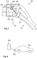
- Cable 101 is further conducted from the front portion 113 to the back portion 111 of the charging connector 100, from which it lead to a charging station 400 as shown in Fig. 4 .
- the purpose of the overall design is to have a triple mechanical protection of the contacts that is guaranteed by the contact holder 102, the inner casing 103, and the external casing 104, and that is further guaranteed by a double IP protection that is guaranteed by the contact holder 102 and the inner casing 103.
- Another reason for separating casing 103 and 104 is weight.
- the severe functional requirements on inner casing 103 lead to fairly robust and heavy design, that is also potentially "sealed for life”.
- the bulkier external casing 104 is built in fairly light manner, with focus on weight reduction and comfort.
- a challenge regards the way in which the latch 115 may guarantee the communication between the car 402 and the charging station 400 or "charging post". Indeed, the good mechanical isolation of the contact elements comes at the expense of good insulation of the latch 115 from the cable 101, which is the component eventually carrying the signal towards the charging station 400.
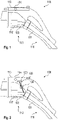
- Fig. 2 shows an schematic diagram of an embodiment, where the problem is solved by a sensor that may detect the position of the latch 115 outside of the inner casing 103 and inside of the external casing 104.
- the sensor 120 could be, for example, a proximity sensor as described above. For example, it may be a Hall sensor that could detect magnets present in the latch 115, or any other sensor type.
- the signal could be transmitted towards the cable 101 via additional cables 106 that would connect the sensor 120 that may be embedded, for example, in a printed circuit board and the cable 101 going through a pass-through connection 108 with adequate IP protection rating.
- Fig. 3 shows an schematic diagram of a further embodiment, in which the signal is transmitted towards the inside of the inner casing 103 in a wireless manner via a wireless signal emitter 107, for example an NFC connection with an RFID antenna, towards the processing unit 108.
- a wireless signal emitter 107 for example an NFC connection with an RFID antenna
- the latter would be connected with a cable 106 to the main cable 101 within the inner casing 103. In such way, a mechanical pass through connection is not required.
- Fig. 4 shows a schematic diagram of a charging station 400 where the charging connector 100 is connected to a socket of the vehicle 402.
- Fig. 5 shows a flow diagram of a method 500 for detecting a secure mechanical connection of a charging connector.
- the method 500 comprises the following steps.
- the charging connector 100 is connected to a vehicle 402.
- the sensor detects the correct mechanical connection of the charging connector 100.
- the sensor sends a signal indicating the correct mechanical connection.
- This step may further comprise an acoustic or optical indication.
- the charging station 400 may receive the signal and may switch on the charging current.
- Sensor power and sensor signal are passed from a sensor cable inside the second casing to the sensor outside the second casing.
- the sensor cable may end inside the inner casing in case of a wireless connection or may be attached to the sensor or a sensor electronics. Additionally or alternatively, the power and the signal may be transmitted wirelessly to the charging station.
Landscapes
- Engineering & Computer Science (AREA)
- Power Engineering (AREA)
- Transportation (AREA)
- Mechanical Engineering (AREA)
- Microelectronics & Electronic Packaging (AREA)
- Charge And Discharge Circuits For Batteries Or The Like (AREA)
Priority Applications (2)
| Application Number | Priority Date | Filing Date | Title |
|---|---|---|---|
| EP21163123.9A EP4059767A1 (fr) | 2021-03-17 | 2021-03-17 | Connecteur de chargement pour véhicule électrique |
| US17/697,348 US12233727B2 (en) | 2021-03-17 | 2022-03-17 | Charging connector for an electric vehicle |
Applications Claiming Priority (1)
| Application Number | Priority Date | Filing Date | Title |
|---|---|---|---|
| EP21163123.9A EP4059767A1 (fr) | 2021-03-17 | 2021-03-17 | Connecteur de chargement pour véhicule électrique |
Publications (1)
| Publication Number | Publication Date |
|---|---|
| EP4059767A1 true EP4059767A1 (fr) | 2022-09-21 |
Family
ID=74947158
Family Applications (1)
| Application Number | Title | Priority Date | Filing Date |
|---|---|---|---|
| EP21163123.9A Pending EP4059767A1 (fr) | 2021-03-17 | 2021-03-17 | Connecteur de chargement pour véhicule électrique |
Country Status (2)
| Country | Link |
|---|---|
| US (1) | US12233727B2 (fr) |
| EP (1) | EP4059767A1 (fr) |
Cited By (1)
| Publication number | Priority date | Publication date | Assignee | Title |
|---|---|---|---|---|
| NO348632B1 (en) * | 2024-04-29 | 2025-04-14 | Evly As | Power output connector assembly |
Families Citing this family (7)
| Publication number | Priority date | Publication date | Assignee | Title |
|---|---|---|---|---|
| DE102018131610A1 (de) * | 2018-12-10 | 2020-06-10 | Phoenix Contact E-Mobility Gmbh | Ladestecker mit einer Rastverbindungsdetektion |
| US11390178B1 (en) * | 2021-08-20 | 2022-07-19 | Beta Air, Llc | Connector and method for use for authorizing battery charging for an electric vehicle |
| USD1122193S1 (en) * | 2021-10-29 | 2026-04-14 | ABB E-mobility B.V. | Electric vehicle charging connector |
| KR102698311B1 (ko) * | 2022-11-30 | 2024-08-26 | 현대모비스 주식회사 | 충전건 분리 장치 |
| USD1098027S1 (en) * | 2023-09-29 | 2025-10-14 | Honda Motor Co., Ltd. | Electrical connector |
| TWI873996B (zh) * | 2023-11-22 | 2025-02-21 | 緯創資通股份有限公司 | 磁吸鎖及其操作方法 |
| TWI909801B (zh) * | 2024-11-06 | 2025-12-21 | 鴻海精密工業股份有限公司 | 充電槍及充電設備 |
Citations (5)
| Publication number | Priority date | Publication date | Assignee | Title |
|---|---|---|---|---|
| DE102011004648A1 (de) * | 2011-02-24 | 2012-08-30 | Kiekert Ag | Ladeeinrichtung mit Spindelantrieb für ein Elektrofahrzeug |
| DE102012203312A1 (de) * | 2011-03-08 | 2012-09-13 | Gm Global Technology Operations, Llc | Passives Ladekabel-Lösesystem für ein elektrisches Fahrzeug |
| US20130271075A1 (en) * | 2012-04-13 | 2013-10-17 | Carlos Eduardo Restrepo | Portable electric vehicle recharging device |
| US20140170889A1 (en) * | 2012-12-13 | 2014-06-19 | Kabushiki Kaisha Tokai Rika Denki Seisakusho | Lock device |
| WO2020120288A1 (fr) * | 2018-12-10 | 2020-06-18 | Phoenix Contact E-Mobility Gmbh | Prise de charge ayant une détection de liaison par encliquetage |
Family Cites Families (19)
| Publication number | Priority date | Publication date | Assignee | Title |
|---|---|---|---|---|
| JP3292278B2 (ja) * | 1995-12-06 | 2002-06-17 | 矢崎総業株式会社 | 電気自動車の充電用コネクタ |
| JPH09161882A (ja) * | 1995-12-06 | 1997-06-20 | Yazaki Corp | 電気自動車の充電用コネクタ |
| JP2002324621A (ja) * | 2001-04-24 | 2002-11-08 | Yazaki Corp | コネクタ |
| JP5123144B2 (ja) * | 2008-11-21 | 2013-01-16 | 矢崎総業株式会社 | 充電用コネクタ |
| JP4898855B2 (ja) * | 2009-02-04 | 2012-03-21 | 矢崎総業株式会社 | コネクタ |
| JP5392151B2 (ja) * | 2010-03-09 | 2014-01-22 | 住友電装株式会社 | 充電用コネクタ |
| JP5443270B2 (ja) * | 2010-05-27 | 2014-03-19 | 株式会社東海理化電機製作所 | プラグロック装置 |
| JP5645077B2 (ja) * | 2011-03-17 | 2014-12-24 | 住友電装株式会社 | 充電用コネクタ |
| JP5798935B2 (ja) * | 2012-01-17 | 2015-10-21 | 矢崎総業株式会社 | 電気コネクタ |
| JP5939927B2 (ja) * | 2012-08-06 | 2016-06-22 | 矢崎総業株式会社 | 充電コネクタ |
| JP6055260B2 (ja) * | 2012-10-05 | 2016-12-27 | 矢崎総業株式会社 | 充電コネクタ |
| JP5878457B2 (ja) * | 2012-12-13 | 2016-03-08 | 株式会社東海理化電機製作所 | 充電ケーブルロック装置 |
| JP6299948B2 (ja) * | 2013-10-16 | 2018-03-28 | 三菱自動車工業株式会社 | 車両の充電口構造 |
| DE102015113875A1 (de) * | 2015-08-21 | 2017-02-23 | Phoenix Contact E-Mobility Gmbh | Steckverbinderteil mit einem Verriegelungselement |
| US10658802B2 (en) * | 2016-06-24 | 2020-05-19 | Gyrus Acmi, Inc. | Gravity plug and connector |
| US10348038B2 (en) * | 2017-07-21 | 2019-07-09 | Ford Global Technologies, Llc | Soft lock to secure an EVSE-to-EV charging connector |
| JP7083354B2 (ja) * | 2017-10-10 | 2022-06-10 | 株式会社村上開明堂 | 車両インレット用ポートロックアクチュエータ装置 |
| EP4000990A1 (fr) * | 2020-11-19 | 2022-05-25 | ABB Schweiz AG | Connecteur de charge de véhicule électrique à refroidissement actif |
| EP4186742A1 (fr) * | 2021-11-25 | 2023-05-31 | ABB E-mobility B.V. | Connecteur de recharge de véhicule électrique à inertie thermique et procédé |
-
2021
- 2021-03-17 EP EP21163123.9A patent/EP4059767A1/fr active Pending
-
2022
- 2022-03-17 US US17/697,348 patent/US12233727B2/en active Active
Patent Citations (5)
| Publication number | Priority date | Publication date | Assignee | Title |
|---|---|---|---|---|
| DE102011004648A1 (de) * | 2011-02-24 | 2012-08-30 | Kiekert Ag | Ladeeinrichtung mit Spindelantrieb für ein Elektrofahrzeug |
| DE102012203312A1 (de) * | 2011-03-08 | 2012-09-13 | Gm Global Technology Operations, Llc | Passives Ladekabel-Lösesystem für ein elektrisches Fahrzeug |
| US20130271075A1 (en) * | 2012-04-13 | 2013-10-17 | Carlos Eduardo Restrepo | Portable electric vehicle recharging device |
| US20140170889A1 (en) * | 2012-12-13 | 2014-06-19 | Kabushiki Kaisha Tokai Rika Denki Seisakusho | Lock device |
| WO2020120288A1 (fr) * | 2018-12-10 | 2020-06-18 | Phoenix Contact E-Mobility Gmbh | Prise de charge ayant une détection de liaison par encliquetage |
Cited By (1)
| Publication number | Priority date | Publication date | Assignee | Title |
|---|---|---|---|---|
| NO348632B1 (en) * | 2024-04-29 | 2025-04-14 | Evly As | Power output connector assembly |
Also Published As
| Publication number | Publication date |
|---|---|
| US20220297554A1 (en) | 2022-09-22 |
| US12233727B2 (en) | 2025-02-25 |
Similar Documents
| Publication | Publication Date | Title |
|---|---|---|
| US12233727B2 (en) | Charging connector for an electric vehicle | |
| JP5834229B2 (ja) | 給電制御装置 | |
| US10340494B2 (en) | Electrical bus bar comprising a sensor unit | |
| EP2783901B1 (fr) | Dispositif de contrôle d'alimentation pour chargement de une vehicule élécrique | |
| US9674972B2 (en) | Modular electronic system and bus subscriber | |
| US10424835B2 (en) | Door handle and antenna unit | |
| US20220077638A1 (en) | Charging socket with interface | |
| US20210098906A1 (en) | Sensor device for an electrical terminal arrangement, electrical terminal arrangement, electrical terminal block, switchgear cabinet and read-out device | |
| CN109997248A (zh) | 用于使电蓄能单元电连接的连接装置 | |
| US6356052B2 (en) | Waterproof inductive charging paddle | |
| EP2783902B1 (fr) | Dispositif de contrôle d'alimentation pour charger une voiture électrique | |
| CN103999283B (zh) | 用于传输来自电池单元的信息的装置和方法以及电池单元 | |
| US9046392B2 (en) | Displacement measuring apparatus | |
| JPWO2017130762A1 (ja) | 通信装置 | |
| US11912149B2 (en) | Misalignment detection device and coil device | |
| CN1211351A (zh) | 带外壳的设备 | |
| CN218569415U (zh) | 一种连接器及一种车辆 | |
| CN221487703U (zh) | 无线通讯装置、电池模组、电池包和车辆 | |
| JPH1118306A (ja) | 電気自動車充電用コネクタ | |
| JP5386843B2 (ja) | 給電器、受電器並びに非接触型データ及び電力伝送装置 | |
| CN223613110U (zh) | 巡检机器人的供电机构和巡检机器人 | |
| US20240159830A1 (en) | Test device | |
| JP2014103847A (ja) | 給電制御装置 | |
| JP5834187B2 (ja) | 給電制御装置 | |
| CN114614539B (zh) | 供电设备及电子设备系统 |
Legal Events
| Date | Code | Title | Description |
|---|---|---|---|
| PUAI | Public reference made under article 153(3) epc to a published international application that has entered the european phase |
Free format text: ORIGINAL CODE: 0009012 |
|
| STAA | Information on the status of an ep patent application or granted ep patent |
Free format text: STATUS: THE APPLICATION HAS BEEN PUBLISHED |
|
| AK | Designated contracting states |
Kind code of ref document: A1 Designated state(s): AL AT BE BG CH CY CZ DE DK EE ES FI FR GB GR HR HU IE IS IT LI LT LU LV MC MK MT NL NO PL PT RO RS SE SI SK SM TR |
|
| RAP1 | Party data changed (applicant data changed or rights of an application transferred) |
Owner name: ABB-E-MOBILITY B.V. |
|
| STAA | Information on the status of an ep patent application or granted ep patent |
Free format text: STATUS: REQUEST FOR EXAMINATION WAS MADE |
|
| 17P | Request for examination filed |
Effective date: 20230320 |
|
| RBV | Designated contracting states (corrected) |
Designated state(s): AL AT BE BG CH CY CZ DE DK EE ES FI FR GB GR HR HU IE IS IT LI LT LU LV MC MK MT NL NO PL PT RO RS SE SI SK SM TR |