EP4059781A1 - Gehäuse für elektrische komponenten eines kraftfahrzeugs - Google Patents
Gehäuse für elektrische komponenten eines kraftfahrzeugs Download PDFInfo
- Publication number
- EP4059781A1 EP4059781A1 EP22162208.7A EP22162208A EP4059781A1 EP 4059781 A1 EP4059781 A1 EP 4059781A1 EP 22162208 A EP22162208 A EP 22162208A EP 4059781 A1 EP4059781 A1 EP 4059781A1
- Authority
- EP
- European Patent Office
- Prior art keywords
- electrical
- box
- motor vehicle
- housing
- fixing
- Prior art date
- Legal status (The legal status is an assumption and is not a legal conclusion. Google has not performed a legal analysis and makes no representation as to the accuracy of the status listed.)
- Pending
Links
Images





Classifications
-
- B—PERFORMING OPERATIONS; TRANSPORTING
- B60—VEHICLES IN GENERAL
- B60R—VEHICLES, VEHICLE FITTINGS, OR VEHICLE PARTS, NOT OTHERWISE PROVIDED FOR
- B60R16/00—Electric or fluid circuits specially adapted for vehicles and not otherwise provided for; Arrangement of elements of electric or fluid circuits specially adapted for vehicles and not otherwise provided for
- B60R16/02—Electric or fluid circuits specially adapted for vehicles and not otherwise provided for; Arrangement of elements of electric or fluid circuits specially adapted for vehicles and not otherwise provided for electric constitutive elements
- B60R16/023—Electric or fluid circuits specially adapted for vehicles and not otherwise provided for; Arrangement of elements of electric or fluid circuits specially adapted for vehicles and not otherwise provided for electric constitutive elements for transmission of signals between vehicle parts or subsystems
- B60R16/0239—Electronic boxes
-
- H—ELECTRICITY
- H05—ELECTRIC TECHNIQUES NOT OTHERWISE PROVIDED FOR
- H05K—PRINTED CIRCUITS; CASINGS OR CONSTRUCTIONAL DETAILS OF ELECTRIC APPARATUS; MANUFACTURE OF ASSEMBLAGES OF ELECTRICAL COMPONENTS
- H05K5/00—Casings, cabinets or drawers for electric apparatus
- H05K5/0026—Casings, cabinets or drawers for electric apparatus provided with connectors and printed circuit boards [PCB], e.g. automotive electronic control units
- H05K5/0065—Casings, cabinets or drawers for electric apparatus provided with connectors and printed circuit boards [PCB], e.g. automotive electronic control units wherein modules are associated together, e.g. electromechanical assemblies, modular structures
-
- H—ELECTRICITY
- H05—ELECTRIC TECHNIQUES NOT OTHERWISE PROVIDED FOR
- H05K—PRINTED CIRCUITS; CASINGS OR CONSTRUCTIONAL DETAILS OF ELECTRIC APPARATUS; MANUFACTURE OF ASSEMBLAGES OF ELECTRICAL COMPONENTS
- H05K5/00—Casings, cabinets or drawers for electric apparatus
- H05K5/0026—Casings, cabinets or drawers for electric apparatus provided with connectors and printed circuit boards [PCB], e.g. automotive electronic control units
- H05K5/0073—Casings, cabinets or drawers for electric apparatus provided with connectors and printed circuit boards [PCB], e.g. automotive electronic control units having specific features for mounting the housing on an external structure
-
- H—ELECTRICITY
- H05—ELECTRIC TECHNIQUES NOT OTHERWISE PROVIDED FOR
- H05K—PRINTED CIRCUITS; CASINGS OR CONSTRUCTIONAL DETAILS OF ELECTRIC APPARATUS; MANUFACTURE OF ASSEMBLAGES OF ELECTRICAL COMPONENTS
- H05K7/00—Constructional details common to different types of electric apparatus
- H05K7/14—Mounting supporting structure in casing or on frame or rack
- H05K7/1422—Printed circuit boards receptacles, e.g. stacked structures, electronic circuit modules or box like frames
- H05K7/1427—Housings
- H05K7/1432—Housings specially adapted for power drive units or power converters
- H05K7/14327—Housings specially adapted for power drive units or power converters having supplementary functional units, e.g. data transfer modules or displays or user interfaces
-
- H—ELECTRICITY
- H02—GENERATION; CONVERSION OR DISTRIBUTION OF ELECTRIC POWER
- H02M—APPARATUS FOR CONVERSION BETWEEN AC AND AC, BETWEEN AC AND DC, OR BETWEEN DC AND DC, AND FOR USE WITH MAINS OR SIMILAR POWER SUPPLY SYSTEMS; CONVERSION OF DC OR AC INPUT POWER INTO SURGE OUTPUT POWER; CONTROL OR REGULATION THEREOF
- H02M1/00—Details of apparatus for conversion
- H02M1/32—Means for protecting converters other than automatic disconnection
- H02M1/327—Means for protecting converters other than automatic disconnection against abnormal temperatures
-
- H—ELECTRICITY
- H02—GENERATION; CONVERSION OR DISTRIBUTION OF ELECTRIC POWER
- H02M—APPARATUS FOR CONVERSION BETWEEN AC AND AC, BETWEEN AC AND DC, OR BETWEEN DC AND DC, AND FOR USE WITH MAINS OR SIMILAR POWER SUPPLY SYSTEMS; CONVERSION OF DC OR AC INPUT POWER INTO SURGE OUTPUT POWER; CONTROL OR REGULATION THEREOF
- H02M3/00—Conversion of DC power input into DC power output
- H02M3/003—Constructional details, e.g. physical layout, assembly, wiring or busbar connections
-
- H—ELECTRICITY
- H02—GENERATION; CONVERSION OR DISTRIBUTION OF ELECTRIC POWER
- H02M—APPARATUS FOR CONVERSION BETWEEN AC AND AC, BETWEEN AC AND DC, OR BETWEEN DC AND DC, AND FOR USE WITH MAINS OR SIMILAR POWER SUPPLY SYSTEMS; CONVERSION OF DC OR AC INPUT POWER INTO SURGE OUTPUT POWER; CONTROL OR REGULATION THEREOF
- H02M7/00—Conversion of AC power input into DC power output; Conversion of DC power input into AC power output
- H02M7/003—Constructional details, e.g. physical layout, assembly, wiring or busbar connections
Definitions
- the invention relates to a housing for electrical components of a motor vehicle.
- the invention also relates to an electric pack comprising such a box.
- the invention also relates to a method for mounting such an electric pack.
- the invention also relates to a motor vehicle equipped with such an electric pack.
- the invention also relates to a method for mounting such a motor vehicle.
- the 48 Volt battery is intended to power various electrical equipment to reduce carbon emissions.
- the 48 Volt battery is used in some vehicles to power a heating grid to improve the performance of the catalytic converter.
- the 48 Volt battery can also power a small electric motor, also called an alternator-starter, intended to support the internal combustion engine during specific driving phases, in particular restarting the vehicle when implementing the function. Stop and Start.
- the alternator-starter in turn supplies the 48 Volt battery during the driving phases.
- the object of the invention is to provide a device making it possible to overcome the constraints described above.
- the invention makes it possible to produce a device which is simple and reliable and which allows compact installation and optimum connection of new electrical components in the engine compartment.
- the dimensions of the box can allow it to be inserted into a space provided for a 12V electric battery of the L3 type and/or the box can be intended to be installed in an engine compartment of a motor vehicle.
- a first side wall may have an opening intended for connection of electrical components to electrical connectors and a second side wall may have an opening intended for connection of electrical components to a cooling circuit.
- the housing may include arrangements for arranging the electrical components at least substantially parallel to each other.
- the invention further relates to a motor vehicle comprising, in particular comprising in an engine compartment, an electric pack according to the invention.
- the motor vehicle 100 is a motor vehicle of any type, in particular a passenger vehicle or a utility vehicle.
- the motor vehicle 100 is equipped with an engine block comprising a heat engine 40.
- the heat engine is of any type, in particular petrol or diesel.
- the engine block could further comprise an electric motor 50, in particular an alternator-starter 50 to allow the implementation of micro-hybridization.
- the motor vehicle 100 Associated with the heat engine 40, the motor vehicle 100 further comprises a first electrical component or computer, called engine computer 2, which controls the operation of the heat engine.
- engine computer 2 a first electrical component or computer
- the motor vehicle 100 also comprises an exhaust line equipped with a heating grid 70 making it possible to optimize the effectiveness of the post-combustion treatment implemented in the vehicle.
- the motor vehicle 100 Associated with the heating grid 70, the motor vehicle 100 also comprises a second electrical component or computer, called the computer for heating grid 3, which controls the operation of the heating grid.
- a second electrical component or computer called the computer for heating grid 3, which controls the operation of the heating grid.
- the motor vehicle 100 is equipped with a first battery 20 supplying a voltage of 48 Volts intended in particular for the electrical supply of the heating grid 70, and possibly of an electric motor 50.
- the motor vehicle 100 can advantageously also be equipped with a third electrical component making it possible to convert a voltage of 48 Volts into a voltage of 12 Volts.
- the third electrical component is also named first converter 4.
- the motor vehicle 100 is also equipped with a second battery 30 supplying a voltage of 12 Volts intended in particular for the power supply of the electrical and electronic equipment of the motor vehicle 100.
- the second battery 30 is connected to a fourth electrical component, called the module 7, containing fuses. These fuses secure the supply circuits which connect the second battery 30 to the electrical and electronic equipment that it supplies.
- the motor vehicle 100 in particular when it is a utility vehicle, can include one or more additional equipment items 60, specific to the field of use of the utility vehicle.
- This additional equipment is generally powered by a voltage of 12 Volts.
- vehicle 100 may include refrigerators or other equipment consuming a significant amount of 12 Volt voltage.
- the motor vehicle 100 can comprise a fifth electrical component, called second converter 5, making it possible to supply a large quantity of voltage of 12 Volts, by transforming a large surplus of voltage of 48 Volts.
- second converter 5 a fifth electrical component
- the motor vehicle 100 can be equipped with a hydraulic cooling means 80 connected to at least one hydraulic cooling conduit 801.
- the motor vehicle 100 can also be equipped with air cooling means 90 connected to an air duct 901.
- the first, second, third, fourth and fifth electrical components 2, 3, 4, 5, 7 are arranged in a casing 1 according to the invention.
- a sixth electric component, or terminal block 6, is advantageously placed in the box 1.
- the arrangement of the six electrical components 2, 3, 4, 5, 6, 7 in the box 1 constitutes an electric pack 10.
- One of the roles of the electric pack, and more particularly of the box 1, is to optimize the space required to the installation of the six electrical components 2, 3, 4, 5, 6, 7.
- the electric pack 10 is intended to be installed in an engine compartment of a motor vehicle.
- the reduced dimensions of the electrical pack 10, and more particularly of the box 1 allow it to fit into a space equivalent to that traditionally provided for accommodate a 12V type L3 electric battery, particularly in the engine compartment.
- the volume of the electric pack 10 is such that it can fit into a rectangular parallelepiped defined by the following dimensions: 261.7 mm ⁇ 282.6 mm ⁇ 350 mm.
- the motor vehicle 100 further comprises a fixing structure 110 capable of receiving the electric pack 10, in particular capable of being fixed to the casing 1.
- the fixing structure 110 can for example be a bracket initially provided for a 12 Volt battery box.
- the fixing structure 110 could also be the side member of the vehicle 100.
- the structure 110 comprises a substantially horizontal surface intended to be in contact with the lower surface of the casing 1.
- the various electrical components of the box are supplied, via connections 600, either with direct current of 48 Volts, or with direct current of 12 Volts.
- the first circuit relates exclusively to the supply of additional equipment 60. It uses the 12 Volt current generated by converters 4, 5 to supply additional equipment 60 via terminal block 6.
- the second circuit connects the 12 Volt battery 30 and the safety element 7 to the elements of the vehicle 100—other than the additional equipment 60—which are supplied with 12 Volts.
- the engine computer 2 is connected, via a connection 600, to the engine interconnection box 35.
- the second circuit advantageously comprises connections 600 connecting the converters 4, 5 to the interconnection box 35, in particular for recharging the battery 30.
- the terminal block 6 constitutes the only point of entry of the direct current of 48 Volts into the electrical pack 10.
- the terminal block 6 is powered by a signal 48 Volts DC via connection 600 to battery 20.
- the terminal block 6 also constitutes the single output point of the direct current of 48 Volts towards the equipment external to the electrical pack 10 using a direct signal of 48 Volts.
- the supply circuits 600 of the electric motor 50, of the computer for the heating grid 3 and of the heating grid 70 are connected to the terminal block 6.
- circuits 600 connect the terminal block 6 to the converters 4, 5 for their supply by a 48 volt DC signal.
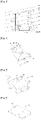
- the housing 1 comprises a first part 11, more particularly represented in the figure 2 and 3 , having five substantially planar faces A, B, C, D, E respectively constituting a base E, of substantially rectangular shape, and four side walls A, B, C, D fixed perpendicularly to the base E.
- the base E of the case has a length of approximately 283 mm (corresponding to the width of the faces B and D, the width of the faces B and D being able however to vary according to the height) and a width of approximately 262 mm (corresponding to the width of sides A and C, the width of sides A and C may however vary depending on the height).
- the faces B and D are in the shape of a rectangular trapezium, their upper side being inclined with respect to a plane containing the base E.
- the heights of the faces A, B, C and D are preferably between 220 mm and 260 mm.
- the box 1 also comprises a 45 degree chamfer placed on the angle formed by the two contiguous side walls A, B.
- the side walls A, B, C, D have main openings or indentations through which at least one electrical, hydraulic or aeraulic connection may in particular extend.
- the wall A has in particular two notches A1, A2 and an opening making it possible to connect the at least one hydraulic cooling conduit 801 to the first and second converters 4, 5.
- the notches A1, A2 each have approximately a height of 42 mm as well as a width of 52 mm for A1 and 47 mm for A2.
- the wall A also has an opening (not shown in the figures) intended for connection to an air duct 901, this connection being made directly on the box 1.
- the wall B also has an opening which extends over a large part of its height in order to provide an opening for the connection of the engine computer 2.
- the opening of the wall B can extend over approximately 232 mm in height and between 170 and 190 mm in width.
- the wall C also has an opening in its upper part to allow the fixing of the security element 7.
- the opening of the wall C can extend over approximately 58 mm in height and 205 mm in width. lenght.
- the wall D also has an opening in its upper part to allow the connection of the converters 4, 5.
- the opening of the wall D can extend over approximately 157 to 181 mm in height and 185 mm in lenght.
- each of the walls A, B, C, and D comes down, in its upper part, to two narrow uprights framing a wide opening.
- Said narrow uprights of two contiguous faces form, two by two, angle brackets BC, CD, DA.
- the angle formed by the walls A and B being chamfered, the walls A and B have in their upper part a common amount AB corresponding to the chamfer.
- the function of the chamfer is to optimize the size of the casing 1, in particular with respect to the environment in which the casing is intended to be inserted. In other embodiments, this chamfer might not be necessary.
- binding elements support surface or binding surface
- binding elements are used interchangeably to designate a binding element.
- a fastener may be, for example, a surface, such as a bearing surface, or a hole in a surface, through which a fastener means extends.
- the base E of the housing is generally continuous over its entire surface, that is to say approximately full, in the sense that there is no opening or indentation for the passage of a connection as is the case of at least one of the side walls. It has three fixing elements, in particular three openings E1, E2, E3 for the passage of screws for fixing the first element of the box to the structure 110 for fixing the vehicle 100.
- the base E as well as the side walls A and C of the first part 11 provide fixing elements, in particular bearing surfaces for positioning and fixing the engine computer 2 and the first current converter 4.
- the base E also comprises two shoulders E4, E5 whose surface is contained in a first support plane P1.
- the support surface P1 is inclined at an angle ⁇ with respect to the support surface of the base E.
- the shoulders E4, E5 will provide fixing elements for mounting the computer for engine 2.
- the side walls A and C arranged facing each other, respectively provide fixing elements comprising bearing surfaces A5, C4 which are contained in a second bearing plane P2, parallel to P1.
- the bearing surfaces A5, C4 will serve as support and fixing support for the first converter 4.
- the side walls A and C also provide fixing elements comprising bearing surfaces for the fixing of a plate 8 arranged between the first converter 4 and the second converter 5.
- the side face A provides two fixing surfaces, A6 and A7, and the side face C provides a fastener C5.
- the plate 8 is arranged along a third fixing plane P3 parallel to the two first fixing planes, P1, P2.
- Plate 8 is more specifically described by figure 4 .
- the surface of plate 8 is distributed along mainly two planes, a lower plane and an upper plane.
- the lower plane includes the first, second and third elements 81, 82, and 83 of the plate 8 which are surfaces intended to be fixed to the fixing elements A6, A7, C5. In other words, after fixing, the lower plane of the plate 8 will be arranged in the third plane P3.
- the plate 8 provides fixing elements 84, 85 intended for fixing the second converter 5 in a fixing plane P4 parallel to the other fixing planes P1, P2, and P3.
- the plate 8 further provides a fixing element 86 intended to fix the safety element 7 of the 12 Volt battery.
- the box 1 in addition to the first part 11, the box 1 according to the invention comprises a cover 12 (represented by the figure 5 ) fitting onto the first part 11, the lid having a main face F, in particular of substantially identical shape to the base E.
- the cover 12 is intended to fit over the upper ends of the uprights AB, BC, CD, DA previously described.
- the upper ends of the uprights AB, BC, CD, DA have been dimensioned so as to be located in the same fixing plane P5, parallel to the other fixing planes.
- the lid 12 is also inclined at an angle ⁇ relative to the bearing surface of the base E.
- the top of the main face F of the lid is thus located in a fixing plane P6 parallel to the other fixing planes, the distance between the planes P5 and P6 corresponding to the thickness of the lid.
- the cover 12 comprises a recess 121 of rectangular shape, arranged on the side edge intended to fit on the side face D of the first part 11 of the case.
- a housing 13 is fixed on top of the main face F of the cover 12, the housing comprising a base in two parts 131, 132 and a cover 133 fitting on the two parts 131, 132 of the base.
- the two parts 131, 132 of the base are in the form of hooks or slots placed opposite one another, so as to delimit a frame.
- An electronic component, in particular terminal block 6, can be placed on cover 12 inside this frame.
- the dimensions of the frame are adapted to the dimensions of the terminal block 6 so as to limit the clearance between the terminal block and the frame.
- the cover 133 represented by the figure 6 , can be nested on the frame in order to close the space defined by the frame.
- the assembly of the base 131, 132 and of the cover 133 constitutes an element for fixing an electrical component in the case 1, in particular an element for fixing the terminal block 6.
- the height of the two parts 131, 132 of the base is defined so as to arrange the cover of the housing 133 along a plane P7 parallel to P6.
- the cover 133 further comprises a fixing element 134 on its upper surface, the fixing element being intended for the computer 3 of the heating grid.
- the fixing element comprises four screws or four fixing pins intended to be inserted into the eyelets of the computer 3.
- the box 1, associated with the plate 8 provides elements E4, E5, A3, A4, A5, A6, C2, C3, C4, C5, 81, 82, 83, 84, 85, 86, AB, BC, CD, DA, 131, 132, 133, 134 for fixing the electrical components 2, 3, 4, 5, 6, 7 to the box 1. Furthermore the box 1 provides elements E1, E2 , E3 for fixing to the fixing structure 110 of the motor vehicle 100.
- the housing and the fixing elements provided by the housing are defined to arrange the electrical components 2, 3, 4, 5, 6 one above the other, in planes P1, P2, P4, P5, P6, P7 substantially parallel to each other and each forming an angle ⁇ with the lower surface of the casing 1.
- the lower surface of the casing 1 is itself arranged along a substantially horizontal plane via the structure fixing 110 of the motor vehicle 100.
- the electrical components 2, 3, 4, 5, 6 are inclined with respect to a horizontal plane, in particular by an angle substantially equal to a.
- the angle ⁇ must be greater than or equal to 8 degrees.
- the electrical components could be arranged in another orientation, for example vertical or substantially vertical.
- Such an embodiment could be advantageous in situations where the size of the box is constrained in height.
- such an embodiment could be preferable when the space available for installing the electric pack in the vehicle 100 is of a height less than its other dimensions, in particular its width and/or its depth.
- the method of assembling an electrical pack comprises nine steps, E11 to E19, which are executed successively.
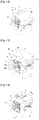
- a first step E11 for mounting the pack 10 is illustrated by the figure 8 .
- the first step E11 is a step of fitting the computer for engine 2 on the base E of the box 1.
- the computer for engine 2 is placed in support on the fixing elements E4, E5, these fixing elements (more specifically visible in the figure 2 , 3 and 8 ) being made by two shoulders of the base E of the housing 1.
- the engine computer 2 is then fixed by screws to the fixing elements E4, E5, by means of fixing lugs present on the computer 2.
- A3, A4, C2, C3 are made on the side faces A and C to provide a passage for the attachment lugs of the engine computer 2.
- the engine computer 2 is arranged so as to orient its so-called connection face towards the face B of the first element 11 of housing 1.
- the connection side of computer 2 has fins for mechanically locking computer 2 to the associated electrical circuit.
- face B is wide open to be able to perform this mechanical locking after the computer has been placed in housing 1.
- a second assembly step E12 is illustrated by the figure 9 .
- the second step E12 is a step of fitting the first converter 4 above the engine computer 2.
- the first converter 4 is placed in support on the fixing elements A5 and C4 provided respectively by the side faces A and C.
- the first converter 4 includes three fixing lugs for its fixing by screws to the fixing elements A5 and C4.
- the first converter 4 could comprise a different number of fixings; in this case, the box 1 would then be adapted to provide the appropriate fixing elements.
- the first converter 4 has connection end pieces intended for connection to a hydraulic conduit 801.
- the connection end pieces of the first converter 4 are advantageously arranged in openings A1, A2 made on the side face A .
- the first converter 4 has an electrical connection socket intended for a connection 600 of the first converter 4 to the terminal block 6.
- the connection socket of the first converter 4 is advantageously arranged opposite a wide opening made on the side face D.
- a third assembly step E13 is illustrated in the figure 10 .
- the third step E13 is a step of laying the plate 8 above the first converter 4.
- the fixing plate 8 is placed in support on the fixing elements A6, A7 and C5 provided respectively by the side faces A and C. Screw fixing is made between the first, second and third elements 81, 82, 83 of the plate 8 and the fixing elements A6, A7 and C5 of the side faces A and C of the box 1.
- a fourth assembly step E14 is illustrated in the figure 11 .
- the fourth step E14 is a step of placing the second converter 5 above the plate 8.
- the second converter 5 is placed in support on the fixing elements 84 and 85 provided by the upper plane of the plate 8.
- the second converter 5 comprises three fixing ears for its fixing by screws advantageously arranged on the fixing elements 84 and 85.
- the first and the second converter 4, 5 are arranged respectively in the planes P3 and P5, and separated from one of the other by the plate 8.
- the plate 8 preserves a free space between the planes P3 and P5, this free space allowing better ventilation and better cooling of the converters 4, 5.
- the second converter 5 has connection end pieces intended for connection to a hydraulic conduit 801.
- the connection end pieces of the second converter 5 are advantageously arranged in a large opening made on the side face A.
- the second converter 5 has an electrical connection socket intended for a connection 600 of the second converter 5 to the terminal block 6.
- the connection socket of the second converter 5 is advantageously arranged facing the wide opening made on the side face D.
- a fifth assembly step E15 is illustrated by the figure 12 .
- the fifth step E15 is a step of interlocking the cover 12 of the box 1 on the first part 11 of the box 1.
- the cover 12 of the box is arranged to rest on the upper part of the uprights AB, BC, CD, DA of the first part of the casing 1.
- the cover 12 can be fixed by clipping and/or held by screws on the first part 11 of the casing.
- the recess 121 of the cover is advantageously arranged above the side face D of the box, so as to facilitate the passage of the electrical connection 600 of the second converter 5.
- a sixth step E16 and a seventh mounting step E17 are illustrated by the figure 13 .
- the sixth step E16 is a step of placing the electrical terminal block 6 in the base 131, 132 of the housing 13 disposed on the cover 12 of the housing.
- the side face of the terminal block 6 which is oriented towards the side face D of the box provides connections for the elements connected to the 48 Volt circuit, in particular for the 48 Volt battery 20, the converters 4, 5, the electric motor 50, the computer for the heating grid 2 and the heating grid 70.
- it also provides connections for the additional equipment 60 supplied with 12 Volts from the current supplied by the converters 4, 5.
- the seventh step E17 is a step of nesting the cover 133 of the housing 13 on the base 131, 132 of the housing 13.
- the cover 133 of the housing 13 is thus arranged above the frame formed by the base 131, 132, for the fixing of the terminal block 6 in the housing 13.
- the cover 133 can be fixed to the base 131, 132 by screws.
- the eighth step E18 is a step of placing a computer for heating grid 3 on the cover 133 of the housing 13.
- the heating rack calculator has four slots on its side edges for screw.
- the fixing element 134 of the cover 133 has four studs advantageously arranged opposite the housings for the screws of the computer.
- the computer 3 is thus fixed by screws to the cover 133.
- the connectors of the computer 3 are oriented towards the side face D of the case.
- a ninth assembly step E19 is illustrated in the figure 15 .
- the ninth step E19 is a step of fixing the security element 7 to the plate 8, in particular by means of the fixing element 86.
- the connection between the safety element 7 and the fixing element 86 is achieved by a screw and a nut.
- the security element 7 is arranged along the side face C of the case.
- the step of mounting the security element is preferably carried out after the mounting of the two converters 4, 5, i.e. say between steps E14 and E15.
- the steps E16, E17 and E18 of mounting the electrical components 6 and 3 on the cover of the box could be executed before the step E15 of mounting the cover 12 on the first part 11 of the box 1.
- the assembly of the vehicle 100 preferably begins with a first step E21 of fixing the first part 11 of the housing to the fixing structure 110 of the vehicle 100.
- screws can for example be inserted in the fixing elements E1, E2 , E3 of the base E of the casing (these fixing elements being more specifically represented in the picture 2 ).
- the screws are then fixed to the fixing structure 110 by nuts (an embodiment of the fastening structure 110 being illustrated by the figure 18 ).
- the housing 1 is mounted in the motor vehicle in such a way as to orient the side face C of the housing, intended to receive the security element 7, towards the bulkhead of the vehicle, that is to say towards the rear end of the vehicle.
- the assembly of the box 1 makes it possible to preserve a free space around the side face C, in order to preserve a free space around the security element 7 when it is assembled to the box, so as to allow the connection of a clamp on a 12 Volt battery cable (the 12 Volt battery itself being difficult to access for the user since it is located under the body of the vehicle).
- Step E22 comprises the sub-steps E11 to E19 previously described.
- step E21 the side face A of the box is oriented towards the front of the vehicle, this arrangement making it possible to obtain a maximum cooling of all the electrical components of the case.
- the side face D giving access to all of the connectors of the electrical components of the box, is oriented towards the engine block. This arrangement thus simplifies the connection of the electrical components to the motor.
- the method of assembling a vehicle according to the invention comprises, following step E22, three steps E23, E24, E25 of connecting the electrical components 2, 3, 4, 5, 6, 7 of the electrical pack 10 to the other components 20, 30, 40, 50, 60, 70, 80, 90 of the motor vehicle 100.
- the pipes and wiring implementing the connections are represented in the figures 17 to 19 .
- the third step E23 is a step of connecting the at least one hydraulic cooling conduit 801 to the first and second electric converters 4, 5. On each of the converters, the connection requires a first end piece for the entry of the fluid into the converter and a second end piece for the fluid outlet, the fluid circulating under pressure in the converter thanks to the action of a pump located on the hydraulic cooling circuit comprising the at least one hydraulic cooling conduit 801.
- the fourth step E24 is a step of fixing the air duct 901 to the box 1 of the electrical pack 10. This step comprises the connection of the air duct 901 to an opening arranged on the side face A of the box 1.
- the fifth step E25 is a step for connecting all the electrical components to the electrical wiring 600.
- Step E25 includes a sub-step for connecting the 48 Volt battery 20 to terminal block 6.
- Step E25 further comprises a sub-step for connecting terminal block 6 to the various equipment supplied with 48 Volts or 12 Volts via electrical pack 10.
- step E25 therefore comprises connecting terminal block 6 to the electric motor 50, additional equipment 60 and heating grid 70.
- Step E25 also includes a sub-step for connecting terminal block 6 to the other components of electrical pack 10 for their power supply, in particular connecting terminal block 6 to computer 3 and to converters 4, 5.
- Step E25 further comprises a sub-step of connecting the security element 7 to the 12 Volt battery 30, and to the various circuits depending on the security element 7.
- this sub-step includes a connection of the second 12 Volt supply circuit connecting the converters 4, 5 and the engine computer 2 to the 12 Volt battery 30 via the interconnection box 35 and the safety element 7.
- step E23, E24, and E25 could be performed before all or part of the steps for mounting the electrical pack.
- all or part of the sub-steps of step E25 of electrical connection could be distributed before, during or after assembly of the electrical pack.
- the sub-step of connection of the security element 7 could be carried out preferably before mounting the security element 7 on the case 1.
- the box according to the invention provides a compact structure for an electric pack comprising in particular the components necessary for the use of a 48V battery in the vehicle 100.
- the electric pack thus structured by the box is compact enough to be housed in the engine compartment, in a location initially allocated to a 12 Volt battery.
- a 48 Volt battery can be fitted in a vehicle initially designed to house only a 12 Volt battery.
- the development of the 48 Volt battery is thus possible by installing the 12 Volt and 48 Volt batteries under the body of the vehicle, and by installing the electric pack in the location initially provided for the 12 Volt battery.
- the assembly of the electrical components in the vehicle is facilitated by the simplicity of assembly of these elements in the housing, due to the accessibility of the fixing structures provided by the housing.
- the electrical, hydraulic and a somehowlic connections are also facilitated by the spatial distribution of the connection connectors on different faces of the pack.
- the box has also been designed according to a logic of accessibility of the components of the electrical pack, meeting both ergonomic and safety criteria.
- the safety element of the 12 Volt battery has been arranged in such a way as to make it accessible by a user.
- the engine computer has been placed at the very bottom of the case so as to complicate and delay its access in the event of a malicious act on the vehicle.
- the electrical pack groups together in a reduced space various components connected to each other, which makes it possible to reduce the length, and therefore the cost, of the electrical wiring between these components.
Landscapes
- Engineering & Computer Science (AREA)
- Microelectronics & Electronic Packaging (AREA)
- Mechanical Engineering (AREA)
- Human Computer Interaction (AREA)
- Arrangement Or Mounting Of Propulsion Units For Vehicles (AREA)
- Casings For Electric Apparatus (AREA)
Applications Claiming Priority (1)
| Application Number | Priority Date | Filing Date | Title |
|---|---|---|---|
| FR2102630A FR3120832B1 (fr) | 2021-03-16 | 2021-03-16 | Boîtier pour composants électriques d’un véhicule automobile. |
Publications (1)
| Publication Number | Publication Date |
|---|---|
| EP4059781A1 true EP4059781A1 (de) | 2022-09-21 |
Family
ID=77519151
Family Applications (1)
| Application Number | Title | Priority Date | Filing Date |
|---|---|---|---|
| EP22162208.7A Pending EP4059781A1 (de) | 2021-03-16 | 2022-03-15 | Gehäuse für elektrische komponenten eines kraftfahrzeugs |
Country Status (2)
| Country | Link |
|---|---|
| EP (1) | EP4059781A1 (de) |
| FR (1) | FR3120832B1 (de) |
Citations (8)
| Publication number | Priority date | Publication date | Assignee | Title |
|---|---|---|---|---|
| JP2002026535A (ja) * | 2000-07-03 | 2002-01-25 | Suzuki Motor Corp | 電動車両の電装品ケース |
| US20090022206A1 (en) * | 2005-04-28 | 2009-01-22 | Honda Motor Co., Ltd. | Temperature sensor mounting structure and battery module structure |
| US20120118653A1 (en) * | 2009-07-28 | 2012-05-17 | Honda Motor Co., Ltd. | In-vehicle electronic component disposing construction for electronic component for electric motor for driving vehicle |
| JP2012098008A (ja) * | 2010-11-05 | 2012-05-24 | Mitsubishi Heavy Ind Ltd | 車両輸送用冷凍ユニット |
| CN101927739B (zh) * | 2010-09-17 | 2012-07-11 | 湖南南车时代电动汽车股份有限公司 | 一种电动汽车电气部件安装布置方法及电气箱 |
| WO2019207713A1 (ja) * | 2018-04-26 | 2019-10-31 | 本田技研工業株式会社 | 電動車両 |
| CN111245199A (zh) * | 2018-11-29 | 2020-06-05 | 湖南中车时代电动汽车股份有限公司 | 一种变流器 |
| CN211671135U (zh) * | 2020-04-08 | 2020-10-13 | 洛阳超特电源科技有限公司 | 电动汽车用高压箱 |
-
2021
- 2021-03-16 FR FR2102630A patent/FR3120832B1/fr active Active
-
2022
- 2022-03-15 EP EP22162208.7A patent/EP4059781A1/de active Pending
Patent Citations (8)
| Publication number | Priority date | Publication date | Assignee | Title |
|---|---|---|---|---|
| JP2002026535A (ja) * | 2000-07-03 | 2002-01-25 | Suzuki Motor Corp | 電動車両の電装品ケース |
| US20090022206A1 (en) * | 2005-04-28 | 2009-01-22 | Honda Motor Co., Ltd. | Temperature sensor mounting structure and battery module structure |
| US20120118653A1 (en) * | 2009-07-28 | 2012-05-17 | Honda Motor Co., Ltd. | In-vehicle electronic component disposing construction for electronic component for electric motor for driving vehicle |
| CN101927739B (zh) * | 2010-09-17 | 2012-07-11 | 湖南南车时代电动汽车股份有限公司 | 一种电动汽车电气部件安装布置方法及电气箱 |
| JP2012098008A (ja) * | 2010-11-05 | 2012-05-24 | Mitsubishi Heavy Ind Ltd | 車両輸送用冷凍ユニット |
| WO2019207713A1 (ja) * | 2018-04-26 | 2019-10-31 | 本田技研工業株式会社 | 電動車両 |
| CN111245199A (zh) * | 2018-11-29 | 2020-06-05 | 湖南中车时代电动汽车股份有限公司 | 一种变流器 |
| CN211671135U (zh) * | 2020-04-08 | 2020-10-13 | 洛阳超特电源科技有限公司 | 电动汽车用高压箱 |
Also Published As
| Publication number | Publication date |
|---|---|
| FR3120832A1 (fr) | 2022-09-23 |
| FR3120832B1 (fr) | 2025-03-14 |
Similar Documents
| Publication | Publication Date | Title |
|---|---|---|
| FR2883665A1 (fr) | Dispositif d'alimentation electrique pour vehicule automobile | |
| EP3058606A1 (de) | Stromspeichereinheit und montageverfahren für solch eine einheit | |
| FR3041906A1 (fr) | Agencement de support de batterie pour vehicule hybride. | |
| FR2976731A1 (fr) | Ensemble de batterie de puissance | |
| FR3076175A1 (fr) | Equipement electrique a paroi deportee | |
| EP3231069A1 (de) | Kompakte architektur eines elektroantriebs für kraftfahrzeuge | |
| EP3501910B1 (de) | Gehäuseelement für elektrische ausrüstung | |
| EP4059781A1 (de) | Gehäuse für elektrische komponenten eines kraftfahrzeugs | |
| FR2678876A1 (fr) | Boitier pour recevoir des composants dans des vehicules automobiles. | |
| EP3535791A1 (de) | Einheitliches modul für ein batteriepack und batteriepack | |
| FR3122041A1 (fr) | Carter de batterie électrique étanche | |
| FR3073096B1 (fr) | Barre d'isolation electrique, notamment pour un module electronique de puissance d'un onduleur | |
| EP4117944B1 (de) | Anordnung zur befestigung eines spannungswandlers und eines thermostats | |
| FR2982094A1 (fr) | Agencement de connexion electrique de cables applicable a un boitier de convertisseur alternatif-continu | |
| EP2477253A1 (de) | Vorrichtung zur Aufnahme einer Vielzahl von Batterien | |
| FR2998760A1 (fr) | Variateur de vitesse et systeme incluant une architecture pour renforcer l'etancheite du variateur de vitesse | |
| WO2020120245A1 (fr) | Ensemble d'un bloc capacitif avec organes de retenue intégrés | |
| WO2024023401A1 (fr) | Ensemble de stockage d'énergie électrique pour un véhicule | |
| WO2020174130A1 (fr) | Platine d'adaptation d'une batterie sur un organe de support | |
| WO2025248063A1 (fr) | Batterie pour véhicule | |
| WO2025108889A1 (fr) | Boîtier pour module de batterie électrique de véhicule et procédé d'assemblage dudit module | |
| WO2023138971A1 (fr) | Dispositif de connexion pour la connexion électrique de deux terminaux de deux cellules élémentaire d'un bloc batterie | |
| FR3141387A1 (fr) | Ensemble d’alimentation électrique d’un véhicule automobile électrique | |
| WO2020065169A1 (fr) | Dispositif de chauffage electrique | |
| FR3093397A1 (fr) | Boitier de module électronique avec organe de de dissipation thermique. |
Legal Events
| Date | Code | Title | Description |
|---|---|---|---|
| PUAI | Public reference made under article 153(3) epc to a published international application that has entered the european phase |
Free format text: ORIGINAL CODE: 0009012 |
|
| STAA | Information on the status of an ep patent application or granted ep patent |
Free format text: STATUS: THE APPLICATION HAS BEEN PUBLISHED |
|
| AK | Designated contracting states |
Kind code of ref document: A1 Designated state(s): AL AT BE BG CH CY CZ DE DK EE ES FI FR GB GR HR HU IE IS IT LI LT LU LV MC MK MT NL NO PL PT RO RS SE SI SK SM TR |
|
| STAA | Information on the status of an ep patent application or granted ep patent |
Free format text: STATUS: REQUEST FOR EXAMINATION WAS MADE |
|
| 17P | Request for examination filed |
Effective date: 20230227 |
|
| RBV | Designated contracting states (corrected) |
Designated state(s): AL AT BE BG CH CY CZ DE DK EE ES FI FR GB GR HR HU IE IS IT LI LT LU LV MC MK MT NL NO PL PT RO RS SE SI SK SM TR |
|
| P01 | Opt-out of the competence of the unified patent court (upc) registered |
Effective date: 20230608 |
|
| STAA | Information on the status of an ep patent application or granted ep patent |
Free format text: STATUS: EXAMINATION IS IN PROGRESS |
|
| 17Q | First examination report despatched |
Effective date: 20250325 |