EP4059809A1 - Elektrische schubkarre - Google Patents
Elektrische schubkarre Download PDFInfo
- Publication number
- EP4059809A1 EP4059809A1 EP19952888.6A EP19952888A EP4059809A1 EP 4059809 A1 EP4059809 A1 EP 4059809A1 EP 19952888 A EP19952888 A EP 19952888A EP 4059809 A1 EP4059809 A1 EP 4059809A1
- Authority
- EP
- European Patent Office
- Prior art keywords
- electric wheelbarrow
- switch
- main body
- wheelbarrow
- electric
- Prior art date
- Legal status (The legal status is an assumption and is not a legal conclusion. Google has not performed a legal analysis and makes no representation as to the accuracy of the status listed.)
- Withdrawn
Links
- 230000005540 biological transmission Effects 0.000 claims abstract description 27
- 239000012528 membrane Substances 0.000 claims description 25
- 230000001276 controlling effect Effects 0.000 claims description 9
- 238000007789 sealing Methods 0.000 claims description 8
- 230000001105 regulatory effect Effects 0.000 claims description 6
- 238000010586 diagram Methods 0.000 description 2
- 238000000034 method Methods 0.000 description 2
- 230000003014 reinforcing effect Effects 0.000 description 2
- 230000003213 activating effect Effects 0.000 description 1
- 238000010276 construction Methods 0.000 description 1
- 238000004519 manufacturing process Methods 0.000 description 1
- 239000000463 material Substances 0.000 description 1
- 239000007779 soft material Substances 0.000 description 1
Images




Classifications
-
- B—PERFORMING OPERATIONS; TRANSPORTING
- B62—LAND VEHICLES FOR TRAVELLING OTHERWISE THAN ON RAILS
- B62B—HAND-PROPELLED VEHICLES, e.g. HAND CARTS OR PERAMBULATORS; SLEDGES
- B62B1/00—Hand carts having only one axis carrying one or more transport wheels; Equipment therefor
- B62B1/18—Hand carts having only one axis carrying one or more transport wheels; Equipment therefor in which the load is disposed between the wheel axis and the handles, e.g. wheelbarrows
-
- B—PERFORMING OPERATIONS; TRANSPORTING
- B62—LAND VEHICLES FOR TRAVELLING OTHERWISE THAN ON RAILS
- B62B—HAND-PROPELLED VEHICLES, e.g. HAND CARTS OR PERAMBULATORS; SLEDGES
- B62B5/00—Accessories or details specially adapted for hand carts
- B62B5/0026—Propulsion aids
- B62B5/0033—Electric motors
- B62B5/0036—Arrangements of motors
- B62B5/004—Arrangements of motors in wheels
-
- B—PERFORMING OPERATIONS; TRANSPORTING
- B62—LAND VEHICLES FOR TRAVELLING OTHERWISE THAN ON RAILS
- B62B—HAND-PROPELLED VEHICLES, e.g. HAND CARTS OR PERAMBULATORS; SLEDGES
- B62B5/00—Accessories or details specially adapted for hand carts
- B62B5/0026—Propulsion aids
- B62B5/0033—Electric motors
- B62B5/0036—Arrangements of motors
- B62B5/0043—One motor drives one wheel
-
- B—PERFORMING OPERATIONS; TRANSPORTING
- B62—LAND VEHICLES FOR TRAVELLING OTHERWISE THAN ON RAILS
- B62B—HAND-PROPELLED VEHICLES, e.g. HAND CARTS OR PERAMBULATORS; SLEDGES
- B62B5/00—Accessories or details specially adapted for hand carts
- B62B5/0026—Propulsion aids
- B62B5/0033—Electric motors
- B62B5/0053—Arrangements of batteries
-
- B—PERFORMING OPERATIONS; TRANSPORTING
- B62—LAND VEHICLES FOR TRAVELLING OTHERWISE THAN ON RAILS
- B62B—HAND-PROPELLED VEHICLES, e.g. HAND CARTS OR PERAMBULATORS; SLEDGES
- B62B5/00—Accessories or details specially adapted for hand carts
- B62B5/0026—Propulsion aids
- B62B5/0066—Transmission of movement
-
- B—PERFORMING OPERATIONS; TRANSPORTING
- B62—LAND VEHICLES FOR TRAVELLING OTHERWISE THAN ON RAILS
- B62B—HAND-PROPELLED VEHICLES, e.g. HAND CARTS OR PERAMBULATORS; SLEDGES
- B62B5/00—Accessories or details specially adapted for hand carts
- B62B5/0026—Propulsion aids
- B62B5/0069—Control
-
- B—PERFORMING OPERATIONS; TRANSPORTING
- B62—LAND VEHICLES FOR TRAVELLING OTHERWISE THAN ON RAILS
- B62B—HAND-PROPELLED VEHICLES, e.g. HAND CARTS OR PERAMBULATORS; SLEDGES
- B62B5/00—Accessories or details specially adapted for hand carts
- B62B5/04—Braking mechanisms; Locking devices against movement
- B62B5/0438—Braking mechanisms; Locking devices against movement hand operated
- B62B5/0442—Braking mechanisms; Locking devices against movement hand operated using a handle bar alone
-
- B—PERFORMING OPERATIONS; TRANSPORTING
- B62—LAND VEHICLES FOR TRAVELLING OTHERWISE THAN ON RAILS
- B62B—HAND-PROPELLED VEHICLES, e.g. HAND CARTS OR PERAMBULATORS; SLEDGES
- B62B5/00—Accessories or details specially adapted for hand carts
- B62B5/04—Braking mechanisms; Locking devices against movement
- B62B5/0438—Braking mechanisms; Locking devices against movement hand operated
Definitions
- the present disclosure relates to the technical field of hand-propelled vehicles, and in particular, to an electric wheelbarrow.
- Hand-propelled vehicles are common means of transportation. Compared with ordinary multi-wheeled hand-propelled vehicles, a wheelbarrow has a simple structure and a small size, and is therefore widely used in production and life, such as in the storage industry and construction industry.
- the pulling or pushing of a conventional wheelbarrow relies on manpower, resulting in high labor intensity and low working efficiency. As a result, an electric wheelbarrow came into being, which wheelbarrow is powered by a drive motor.
- the drive motor, a transmission device, etc. are all installed at a tray or a frame of the electric wheelbarrow, resulting in a complicated overall structure and relatively large size of the electric wheelbarrow.
- the present disclosure provides an electric wheelbarrow.
- the electric wheelbarrow comprises a main body portion, and a power supply device, a power device and a control device which are installed at the main body portion.
- the power supply device and the control device are separately connected to the power device.
- the main body portion comprises a tray, a main body frame for carrying the tray, and a wheel installed at the main body frame.
- the power device comprises a drive device, a transmission device, and a brake device.
- the drive device and the transmission device are disposed in the wheel, the drive device is connected to a hub assembly of the wheel, and the transmission device is connected to a rim of the wheel.
- the drive device comprises a hub motor installed in the wheel, and the hub motor is connected to the transmission device and the hub assembly.
- the hub motor comprises a stator and a rotor, the stator is connected to the hub assembly, and the rotor is connected to the transmission device.
- the transmission device is a gearbox.
- the gearbox is a planetary gearbox.
- the planetary gearbox comprises a sun gear, a planetary gear, a planet carrier and a ring gear.
- the sun gear is connected to the drive device, the sun gear meshes with the planetary gear, the planetary gear is installed at the planet carrier, the ring gear meshes with the planetary gear, and the ring gear is fixedly connected to the rim.
- the power supply device comprises an upper housing and a lower housing.
- the lower housing is fixedly installed at the main body portion, and the upper housing is detachably connected to the lower housing.
- a sealing ring is disposed between the lower housing and the upper housing.
- control device comprises a controller for controlling the power device, and a switch device connected to the controller.
- the controller and the switch device are both disposed on the main body portion.
- the switch device comprises a power membrane switch for controlling the on or off of a power supply of the electric wheelbarrow, a brake device, a motor regulation switch for regulating the operation of the motor when the power supply is turned on, a direction adjustment membrane switch for controlling the electric wheelbarrow to move forward or backward, and a speed regulation membrane switch for regulating a movement speed of the electric wheelbarrow.
- the main body portion is provided with a handle, and the switch device is disposed on the handle.
- the power membrane switch is disposed on an end face of a first end of the handle
- the brake device is disposed on an inner side of the first end
- the motor regulation switch is disposed on an inner side of a second end of the handle
- the direction adjustment membrane switch and the speed regulation membrane switch are disposed on an end face of the second end.
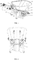
- an embodiment of the present disclosure provides an electric wheelbarrow, comprising a main body portion 1, and a power supply device 2, a power device and a control device which are installed at the main body portion 1.
- the power supply device 2 and the control device are separately connected to the power device.
- the main body portion 1 comprises a tray 11, a main body frame 12 for carrying the tray 11, and a wheel 13 installed at the main body frame 12.
- the bottom of the tray 11 is installed above the main body frame 12 by means of a mounting base 14, and a front end of the tray 11 is further connected to a front end of the main body frame 12 via a fixing rib 15, so that the tray 11 is connected to the main body frame 12 more firmly, thereby making the overall structure of the electric wheelbarrow more stable.
- the wheel 13 is installed in the main body frame 12 below the tray 11 by means of a fixed shaft 16, and two parallel support frames 17 are provided below the main body frame 12. In a non-use state, a bent portion of each of the support frames 17 is in contact with the ground, and the two support frames 17 and the wheel 13 jointly support the electric wheelbarrow to stand on the ground or another working surface.
- a reinforcing structure 18 is further disposed between the two support frames 17 to further improve the structural stability of the electric wheelbarrow. It is also possible that the bent portions of the two support frames 17 that are in contact with the ground are subjected to anti-sliding treatment to prevent the electric wheelbarrow from accidentally sliding when the electric wheelbarrow stands on the ground or another working surface.
- the power device comprises a drive device 3, a transmission device 4, and a brake device 5.
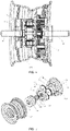
- the drive device 3 and the transmission device 4 are both disposed in the wheel 13, the drive device 3 is connected to a hub assembly 131 of the wheel 13, and the transmission device 4 is connected to a rim 132 of the wheel 13.
- the drive device 3 and the transmission device 4 are both disposed in the wheel 13, which can simplify the overall structure of the electric wheelbarrow, reduce the size of the electric wheelbarrow and facilitate the application of the electric wheelbarrow in various narrow spaces.
- the drive device 3 comprises a hub motor 31 installed in the wheel 13, and the hub motor 31 is connected to the transmission device 4 and the hub assembly 131.
- the hub motor 31 may be connected to the hub assembly 131, and an inner side of the hub motor 31 is connected via a bearing 6 to the fixed shaft 16 passing through the hub assembly 131, thereby fixing the hub motor 31 in the wheel 13.
- An output end of the hub motor 31 is connected to the transmission device 4 via a bearing 6.
- the hub motor 31 comprises a stator 311 and a rotor 312.
- the rotor 312 is located in the stator 311, and an outer side of the stator 311 is connected to the hub assembly 131.
- One end of a rotor shaft 313 of the rotor 312 is connected to the fixed shaft 16 via a bearing 6, and the other end of the rotor shaft 313 is connected to the transmission device 4 via a bearing 6.
- the transmission device 4 is a gearbox.
- the gearbox is a planetary gearbox.
- the planetary gearbox has a compact size, performs transmission steadily, and has a large load-bearing capacity and a long service life, thereby further reducing the size of the electric wheelbarrow.
- the planetary gearbox comprises a sun gear 41 connected to the drive device, a planetary gear 42 meshing with the sun gear 41, a planet carrier 43 for mounting the planetary gear 42, and a ring gear 44 with an inner side meshing with the planetary gear 42.
- the ring gear 44 is fixedly connected to the rim 132.
- the ring gear 44 may be fixedly connected to the rim 132 by means of being connected to a sealing cover 133 that is disposed on the wheel 13 and fixedly connected to the rim 132.
- the hub motor 31 transmits power to the sun gear 41 through the rotor shaft 313 connected to the sun gear 41, such that the sun gear 41 rotates.
- the sun gear 41 drives the planetary gear 42 meshing therewith to rotate
- the planetary gear 42 drives the ring gear 44 meshing therewith to rotate
- the ring gear 44 drives the rim 132 fixedly connected thereto to rotate, thereby driving the wheel 13.
- the brake device 5 comprises a brake wire (not shown) connected to the control device, a brake 51 which is connected to the brake wire and installed at the wheel 13, and a brake disc (not shown) which is connected to the brake 51 and acts on the wheel.
- the brake wire can be pulled by the control device, and the brake wire drives the brake 51 to act on the brake disc, thereby braking the wheel 13.
- the power supply device 2 is disposed behind the tray 11, and the power supply device 2 is connected to the drive device 3 to provide electric energy for the hub motor 31 in the drive device 3.
- the power supply device 2 may be a waterproof battery pack disposed on the main body portion.
- an external plug may be provided on the power supply device 2, to charge the battery pack by an external power supply.
- the power supply device 2 comprises an upper housing 21 and a lower housing 22 that are detachably connected to each other. Only the lower housing 22 is fixedly installed at the main body portion 1. For example, the lower housing may be fixedly installed at the tray 11. A battery in the power supply device 2 is disposed in a cavity formed by the upper housing 21 and the lower housing 22, and the battery may be a storage battery or the like. Therefore, when the battery in the power supply device 2 needs to be repaired or replaced, staff only need to open the upper housing 21 to repair or replace the battery without the need for disassembling the entire power supply device 2.
- a sealing ring is disposed between the lower housing 22 and the upper housing 21 to prevent rainwater and the like from entering the cavity for the power supply device 2 and damaging the battery.
- the sealing ring may be a rubber sealing ring made of a soft material to further improve the sealing performance of the power supply device 2.
- the control device comprises a controller for controlling the power device, and a switch device 7 connected to the controller.
- the controller and the switch device 7 are both disposed on the main body portion 1, for example, on the main body frame 12 of the main body portion 1.
- the switch device 7 may provide a power on/off function of turning on or off a power supply of the electric wheelbarrow, a function of adjusting the operation of the hub motor 31 to adjust a rotation speed of the hub motor 31, and a function of activating or deactivating the brake device 5.
- the switch device 7 may be further configured to provide a function of adjusting a movement speed and/or a movement direction, so as to adjust a movement speed and direction of the electric wheelbarrow.
- the power supply and the drive device 3 can be activated through the switch device 7 and the controller, power output by the hub motor 31 in the drive device 3 can be transmitted to the rim 132 through the transmission device 4 to drive the wheel 13, so as to drive the electric wheelbarrow to move, and drive the electric wheelbarrow to move to a designated position.
- brake kinetic energy is activated through the switch device 7, that is, the brake wire is pulled by the switch device 7, and the brake wire drives the brake 51 to act on the brake disc, thereby implementing the braking of the wheel 13 and making the electric trolley stop moving.
- the controller may include a processor for supporting the electric movement of the electric wheelbarrow performed by the control device, a storage unit for storing program codes of the control device, etc.
- the processor may be a central processing unit (CPU), or may be other general-purpose processors, a digital signal processor (DSP), an application-specific integrated circuit (ASIC), a field-programmable gate array (FPGA) or other programmable logic devices, and the like.
- the general-purpose processor may be a microprocessor or any conventional processor or the like.
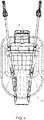
- the switch device 7 comprises a power membrane switch 71 for controlling the on or off of a power supply of the electric wheelbarrow, a brake switch 72, a motor regulation switch 73 for regulating the operation of the motor when the power supply is turned on, a direction adjustment membrane switch 74 for controlling the electric wheelbarrow to move forward or backward, and a speed regulation membrane switch 75 for regulating a movement speed of the electric wheelbarrow.
- an operator can turn on the power membrane switch 71 and the motor regulation switch 73 to activate the hub motor 31.
- the power output by the hub motor 31 can be transmitted to the rim 132 through the transmission device 4, and then drives the wheel 13 to move the electric wheelbarrow.
- the user can adjust the movement speed of the electric wheelbarrow through the motor regulation switch 73 and the speed regulation membrane switch 75 as required.
- the direction adjustment membrane switch 74 may also be used to make the electric wheelbarrow move forward or backward.
- the user can press the brake switch 72 to pull the brake wire, and the brake wire drives the brake 51 to act on the brake disc, thereby braking the wheel 13, so that the electric wheelbarrow stops moving. After the power supply is turned off by means of the power membrane switch 71, the user can safely unload goods from the electric wheelbarrow.
- the main body frame 12 of the main body portion 1 is provided with a handle 19, and the switch device 7 is disposed on the handle 19 to facilitate the operation by the staff as required during the process of using the electric wheelbarrow.
- the switch device 7 may be disposed on a grip portion of the handle 19 to further facilitate the operation by the staff.
- the power membrane switch 71 is disposed on an end face of a first end of the handle 19, the brake switch 72 is disposed on an inner side of the first end, the motor regulation switch 73 is disposed on an inner side of a second end of the handle 19, and the direction adjustment membrane switch 74 and the speed regulation membrane switch 75 are disposed on an end face of the second end.
- the staff can turn on or off each switch as required, facilitating the operation.
Landscapes
- Engineering & Computer Science (AREA)
- Chemical & Material Sciences (AREA)
- Combustion & Propulsion (AREA)
- Transportation (AREA)
- Mechanical Engineering (AREA)
- Handcart (AREA)
Applications Claiming Priority (1)
| Application Number | Priority Date | Filing Date | Title |
|---|---|---|---|
| PCT/CN2019/117982 WO2021092790A1 (zh) | 2019-11-13 | 2019-11-13 | 电动独轮手推车 |
Publications (2)
| Publication Number | Publication Date |
|---|---|
| EP4059809A1 true EP4059809A1 (de) | 2022-09-21 |
| EP4059809A4 EP4059809A4 (de) | 2023-08-09 |
Family
ID=75911341
Family Applications (1)
| Application Number | Title | Priority Date | Filing Date |
|---|---|---|---|
| EP19952888.6A Withdrawn EP4059809A4 (de) | 2019-11-13 | 2019-11-13 | Elektrische schubkarre |
Country Status (7)
| Country | Link |
|---|---|
| US (1) | US20220274635A1 (de) |
| EP (1) | EP4059809A4 (de) |
| CN (1) | CN114026009A (de) |
| AU (1) | AU2019473790A1 (de) |
| CA (1) | CA3157256A1 (de) |
| MX (1) | MX2022005481A (de) |
| WO (1) | WO2021092790A1 (de) |
Families Citing this family (4)
| Publication number | Priority date | Publication date | Assignee | Title |
|---|---|---|---|---|
| US11285982B2 (en) * | 2017-02-22 | 2022-03-29 | Douglas Van Zandt | Elevated pivot bracket for a wheelbarrow |
| JP7203984B2 (ja) * | 2019-08-08 | 2023-01-13 | 株式会社マキタ | 作業機 |
| WO2021249419A1 (en) * | 2020-06-12 | 2021-12-16 | Globe (jiangsu) Co., Ltd. | Electric vehicle |
| US20250388250A1 (en) * | 2024-06-24 | 2025-12-25 | Benjamin P Esh | Smartbarrow powered Wheelbarrow Kit |
Family Cites Families (13)
| Publication number | Priority date | Publication date | Assignee | Title |
|---|---|---|---|---|
| US6470981B1 (en) * | 1999-03-04 | 2002-10-29 | Honda Giken Kogyo Kabushiki Kaisha | Power-assisted hand carrier |
| DE10008451A1 (de) * | 2000-02-23 | 2001-08-30 | Bercher Willi | Schubkarren mit einem elektrischen Antrieb zur Schubkraftunterstützung |
| JP2003011825A (ja) * | 2001-06-28 | 2003-01-15 | Muneo Shioiri | アシスト一輪車 |
| US6481518B1 (en) * | 2001-08-07 | 2002-11-19 | David Wu | Motor drive mounting arrangement for golf cart |
| JP2006082792A (ja) * | 2004-09-17 | 2006-03-30 | Meidensha Corp | 一輪車付き運搬車 |
| JP4494917B2 (ja) * | 2004-09-30 | 2010-06-30 | 本田技研工業株式会社 | 自動二輪車のメータ装置 |
| CN201545042U (zh) * | 2009-09-23 | 2010-08-11 | 李顺德 | 一种电动手推车 |
| CZ22483U1 (cs) * | 2011-06-01 | 2011-07-18 | Isolit-Bravo, Spol. S R.O. | Kolecko pro manuální prepravu materiálu |
| CN203318448U (zh) * | 2013-06-03 | 2013-12-04 | 台州市万达线缆有限公司 | 电动手推车 |
| CN204674619U (zh) * | 2015-05-13 | 2015-09-30 | 西北农林科技大学 | 一种新型电动手推车 |
| CN106043586B (zh) * | 2016-08-14 | 2018-07-31 | 朱幕松 | 小型自平衡独轮电动车 |
| JP6943573B2 (ja) * | 2017-01-31 | 2021-10-06 | 株式会社マキタ | 手押し式運搬車 |
| CN208325266U (zh) * | 2018-06-05 | 2019-01-04 | 青岛鑫时利轮业有限公司 | 电动手推车 |
-
2019
- 2019-11-13 CA CA3157256A patent/CA3157256A1/en active Pending
- 2019-11-13 CN CN201980097773.7A patent/CN114026009A/zh not_active Withdrawn
- 2019-11-13 AU AU2019473790A patent/AU2019473790A1/en active Pending
- 2019-11-13 MX MX2022005481A patent/MX2022005481A/es unknown
- 2019-11-13 WO PCT/CN2019/117982 patent/WO2021092790A1/zh not_active Ceased
- 2019-11-13 US US17/776,387 patent/US20220274635A1/en not_active Abandoned
- 2019-11-13 EP EP19952888.6A patent/EP4059809A4/de not_active Withdrawn
Also Published As
| Publication number | Publication date |
|---|---|
| AU2019473790A1 (en) | 2022-01-27 |
| CA3157256A1 (en) | 2021-05-20 |
| WO2021092790A1 (zh) | 2021-05-20 |
| MX2022005481A (es) | 2022-05-30 |
| EP4059809A4 (de) | 2023-08-09 |
| CN114026009A (zh) | 2022-02-08 |
| US20220274635A1 (en) | 2022-09-01 |
Similar Documents
| Publication | Publication Date | Title |
|---|---|---|
| EP4059809A1 (de) | Elektrische schubkarre | |
| US12122441B2 (en) | Electric handcart | |
| US20250289489A1 (en) | Electric wagon and electronically power assisted wagon | |
| US7392872B2 (en) | Power assisted vehicle | |
| JP2012076575A5 (de) | ||
| CN207311089U (zh) | 一种新型电动车轮 | |
| CN1182002C (zh) | 带辅助动力的车辆 | |
| CN221852002U (zh) | 一种电动手推车 | |
| CN204355188U (zh) | 一种自动运输小车 | |
| CN202624561U (zh) | 节能环保电动自行车 | |
| CN117141560A (zh) | 一种集成驱动及电源的助力轮组及助力车 | |
| CN206908460U (zh) | 减速轮毂电机及轮毂驱动机构 | |
| EP1900397B1 (de) | Motorangetriebener Wagen | |
| CN213150905U (zh) | 一种新能源汽车动力电池出厂前专用存储箱 | |
| CN107280870B (zh) | 一种利用无刷电机和多级行星齿轮减速机构驱动的电动轮椅 | |
| CN207875736U (zh) | 一种双档位机械刹车式手推车 | |
| KR100626197B1 (ko) | 손수레 이송용 전동카트 | |
| CN210000345U (zh) | 动力辅助装置及具有该动力辅助装置的手推车 | |
| CN224097660U (zh) | 一种便携式光伏组件 | |
| CN112360686A (zh) | 一种户外便于安装的风力发电设备 | |
| CN219652562U (zh) | 一种支撑架式迷你电动葫芦 | |
| CN202152084U (zh) | 一种交流充电和太阳能电动摩托车 | |
| CN214165221U (zh) | 一种电动自行车的传动装配机构 | |
| CN103253554B (zh) | 一种移动式柔锁收放器 | |
| JP3235539U (ja) | 保線用電動カート |
Legal Events
| Date | Code | Title | Description |
|---|---|---|---|
| STAA | Information on the status of an ep patent application or granted ep patent |
Free format text: STATUS: THE INTERNATIONAL PUBLICATION HAS BEEN MADE |
|
| PUAI | Public reference made under article 153(3) epc to a published international application that has entered the european phase |
Free format text: ORIGINAL CODE: 0009012 |
|
| STAA | Information on the status of an ep patent application or granted ep patent |
Free format text: STATUS: REQUEST FOR EXAMINATION WAS MADE |
|
| 17P | Request for examination filed |
Effective date: 20211224 |
|
| AK | Designated contracting states |
Kind code of ref document: A1 Designated state(s): AL AT BE BG CH CY CZ DE DK EE ES FI FR GB GR HR HU IE IS IT LI LT LU LV MC MK MT NL NO PL PT RO RS SE SI SK SM TR |
|
| DAV | Request for validation of the european patent (deleted) | ||
| DAX | Request for extension of the european patent (deleted) | ||
| A4 | Supplementary search report drawn up and despatched |
Effective date: 20230712 |
|
| RIC1 | Information provided on ipc code assigned before grant |
Ipc: B62B 5/04 20060101ALN20230706BHEP Ipc: B62B 5/00 20060101ALI20230706BHEP Ipc: B62B 1/18 20060101AFI20230706BHEP |
|
| STAA | Information on the status of an ep patent application or granted ep patent |
Free format text: STATUS: THE APPLICATION IS DEEMED TO BE WITHDRAWN |
|
| 18D | Application deemed to be withdrawn |
Effective date: 20240220 |