EP4059830A2 - Schiffsantrieb, wasserfahrzeug - Google Patents
Schiffsantrieb, wasserfahrzeug Download PDFInfo
- Publication number
- EP4059830A2 EP4059830A2 EP22159192.8A EP22159192A EP4059830A2 EP 4059830 A2 EP4059830 A2 EP 4059830A2 EP 22159192 A EP22159192 A EP 22159192A EP 4059830 A2 EP4059830 A2 EP 4059830A2
- Authority
- EP
- European Patent Office
- Prior art keywords
- duct
- ducts
- width direction
- hull
- marine
- Prior art date
- Legal status (The legal status is an assumption and is not a legal conclusion. Google has not performed a legal analysis and makes no representation as to the accuracy of the status listed.)
- Granted
Links
Images


Classifications
-
- B—PERFORMING OPERATIONS; TRANSPORTING
- B63—SHIPS OR OTHER WATERBORNE VESSELS; RELATED EQUIPMENT
- B63H—MARINE PROPULSION OR STEERING
- B63H5/00—Arrangements on vessels of propulsion elements directly acting on water
- B63H5/07—Arrangements on vessels of propulsion elements directly acting on water of propellers
- B63H5/14—Arrangements on vessels of propulsion elements directly acting on water of propellers characterised by being mounted in non-rotating ducts or rings, e.g. adjustable for steering purpose
-
- B—PERFORMING OPERATIONS; TRANSPORTING
- B63—SHIPS OR OTHER WATERBORNE VESSELS; RELATED EQUIPMENT
- B63H—MARINE PROPULSION OR STEERING
- B63H5/00—Arrangements on vessels of propulsion elements directly acting on water
- B63H5/07—Arrangements on vessels of propulsion elements directly acting on water of propellers
- B63H5/08—Arrangements on vessels of propulsion elements directly acting on water of propellers of more than one propeller
-
- B—PERFORMING OPERATIONS; TRANSPORTING
- B63—SHIPS OR OTHER WATERBORNE VESSELS; RELATED EQUIPMENT
- B63H—MARINE PROPULSION OR STEERING
- B63H5/00—Arrangements on vessels of propulsion elements directly acting on water
- B63H5/07—Arrangements on vessels of propulsion elements directly acting on water of propellers
- B63H5/16—Arrangements on vessels of propulsion elements directly acting on water of propellers characterised by being mounted in recesses; with stationary water-guiding elements; Means to prevent fouling of the propeller, e.g. guards, cages or screens
Definitions
- the present disclosure relates to a marine propulsor that propels a marine vessel.
- Patent Document 1 discloses a marine propulsor that includes a duct and a propeller that is rotatably disposed within the duct.
- Patent Document 1 JP 2013-503784 T
- a marine propulsor in which a propeller is disposed within a duct can achieve lower noise and improved maintainability but often has lower propulsion efficiency than a marine propulsor employing an open propeller.
- a duct propeller type marine propulsor is often more expensive than an open propeller type marine propulsor.
- an open propeller type marine propulsor is often selected rather than a duct propeller type marine propulsor.
- the duct propeller type marine propulsor has a high degree of freedom in design such as layout, size, and rotational speed, and can improve propulsion efficiency.
- the present disclosure has been made in view of the above-described problem, and an object of the present disclosure is to provide a marine propulsor including a duct and a propeller rotatably disposed within the duct, and capable of improving propulsion efficiency.
- a marine propulsor for propelling a marine vessel, which includes: a plurality of ducts arranged below a hull of the marine vessel along a width direction of the hull; and a propeller rotatably disposed inside each of the plurality of ducts, wherein when at least one pair of ducts adjacent to each other in the width direction among the plurality of ducts includes a one-side duct located on one side in the width direction and an other-side duct located on the other side in the width direction, a side surface of the one-side duct on the other side in the width direction is in contact with a side surface of the other-side duct on the one side in the width direction.
- the propulsion efficiency of the marine propulsor including the duct and the propeller rotatably disposed within the duct can be improved.
- FIG. 1 is a diagram schematically illustrating a configuration of a marine vessel 100 including a marine propulsor 1 according to one embodiment. As illustrated in FIG. 1 , the marine vessel 100 includes a hull 102 and the marine propulsor 1 attached to the hull 102 to propel the marine vessel 100.
- the hull 102 has a bow portion 104, which is a portion located at the front of the hull 102, a stern portion 106, which is a portion located at the back of the hull 102, and a ship bottom area 108.
- the bow portion 104 has a shape that reduces resistance the hull 102 receives from fluids such as seawater.
- front-back direction the direction from the stern portion 106 toward the bow portion 104 is the forward direction of the hull 102
- the direction from the bow portion 104 toward the stern portion 106 is the rearward direction of the hull 102.
- the marine propulsor 1 is attached to the ship bottom area 108 so as to be located on the stern portion 106 side of the hull 102.
- the marine vessel 100 is configured such that the travel direction of the hull 102 is adjusted by rotating the marine propulsor 1 about an axis O extending in the up-down direction (so-called oscillating type marine propulsor).
- the marine vessel 100 includes a rudder for adjusting the travel direction of the hull 102.
- FIG. 2 is a diagram schematically illustrating a configuration of a marine propulsor 1 according to one embodiment of the present disclosure.
- FIG. 2 illustrates the marine propulsor 1 viewed from the forward direction.
- the marine propulsor 1 includes a plurality of ducts 2 arranged along the width direction of the hull 102 below the hull 102 of the marine vessel 100, and a propeller 4 rotatably disposed inside each of the plurality of ducts 2.
- width direction D the width direction of the hull 102 is simply referred to as "width direction D”.
- the marine vessel 100 includes a center skeg 110 projecting downward from the ship bottom area 108 of the hull 102.
- the center skeg 110 is provided at the ship bottom area 108 of the hull 102 so as to be located at the center portion in the width direction D, and stabilizes the hull 102.
- the plurality of ducts 2 include a first duct row 6 disposed on one side (starboard side) in the width direction D of the center skeg 110, and a second duct row 8 disposed on the other side (port side) in the width direction D of the center skeg 110.
- the first duct row 6 includes five ducts 2A(2) arranged along the width direction D. That is, four pairs of the ducts 2A and 2A adjacent to each other in the width direction D are formed.
- the second duct row 8 includes five ducts 2B(2) arranged along the width direction D. That is, four pairs of the ducts 2B and 2B adjacent to each other in the width direction D are formed.
- FIG. 3 is a diagram schematically illustrating a configuration of a pair of the ducts 2A and 2A according to one embodiment.
- FIG. 3 illustrates the pair of the ducts 2A and 2A viewed from the forward direction.
- the duct 2A located on one side in the width direction D is referred to as a one-side duct 10
- the duct 2A located on the other side in the width direction D is referred to as an other-side duct 12.
- the configuration illustrated in FIG. 3 may be applied to another pair of the ducts 2A and 2A, or may be applied to a pair of the ducts 2B and 2B adjacent to each other in the width direction D.
- the one-side duct 10 includes an inlet section 14 that forms an inlet 16 of the one-side duct 10.
- the inlet section 14 of the one-side duct 10 is configured such that each of an outer periphery shape and an inner periphery shape has a quadrangular shape.
- Each of the outer periphery shape and the inner periphery shape of the inlet section 14 of the one-side duct 10 is configured such that the wall thickness is constant.
- the resistance that the one-side duct 10 receives from fluid such as seawater can be reduced.
- the outer periphery shape of the inlet section 14 of the one-side duct 10 is not limited to a quadrangular shape, but can be a polygonal shape.
- the inner periphery shape of the inlet section 14 of the one-side duct 10 also has a polygonal shape along the outer periphery shape.
- the one-side duct 10 such as that described above has, for example, a quadrangular cylindrical shape and includes: a top surface 18; a first side surface 20 that extends downward from the one end 18a on the one side in the width direction D of the top surface 18; a second side surface 22 that extends downward from the other end 18b on the other side in the width direction D of the top surface 18; and a bottom surface 24 that connects a bottom end 20a of the first side surface 20 and a bottom end 22a of the second side surface 22.
- the top surface 18 of the one-side duct 10 is in contact with the ship bottom area 108 of the hull 102.
- the second side surface 22 of the one-side duct 10 has a linear shape over the entirety of the extending direction of the one-side duct 10.
- the bottom surface 24 of the one-side duct 10 includes an inclined section 38 that is inclined away from the ship bottom area 108 of the hull 102 toward the other side in the width direction D (center side).
- the inclined section 38 of the bottom surface 24 of the one-side duct 10 is the entirety of the range in which the bottom surface 24 is provided in the width direction D.
- the inclined section 38 of the bottom surface 24 of the one-side duct 10 is a part of a range in which the bottom surface 24 is provided in the width direction D.
- the bottom surface 24 of the one-side duct 10 has a linear shape, but may be curved in a convex shape so that the outer shape changes smoothly.
- the other-side duct 12 includes an inlet section 26 that forms an inlet 28 of the other-side duct 12.
- the inlet section 26 of the other-side duct 12 is configured such that each of an outer periphery shape and an inner periphery shape has a quadrangular shape.
- Each of the outer periphery shape and the inner periphery shape of the inlet section 26 of the other-side duct 12 is configured such that the wall thickness is constant.
- the resistance that the other-side duct 12 receives from fluid such as seawater can be reduced.
- the other-side duct 12 such as that described above has, for example, a quadrangular cylindrical shape and includes: a top surface 30; a first side surface 32 that extends downward from the one end 30a of the top surface 30 on the one side in the width direction D; a second side surface 34 that extends downward from the other end 30b of the top surface 30 on the other side in the width direction D; and a bottom surface 36 that connects a bottom end 32a of the first side surface 32 and a bottom end 34a of the second side surface 34.
- the top surface 30 of the other-side duct 12 is in contact with the ship bottom area 108 of the hull 102.
- the first side surface 32 of the other-side duct 12 has a linear shape over the entirety of the extending direction of the other-side duct 12.
- the bottom surface 36 of the other-side duct 12 includes an inclined section 40 which is inclined away from the ship bottom area 108 of the hull 102 toward the other side in the width direction D (center side).
- the inclined section 40 of the bottom surface 36 of the other-side duct 12 is the entirety of the range in which the bottom surface 36 is provided in the width direction D.
- the inclined section 40 of the bottom surface 36 of the other-side duct 12 is a part of a range in which the bottom surface 36 is provided in the width direction D.
- the bottom surface 36 of the other-side duct 12 has a linear shape, but may be curved in a convex shape so that the outer shape changes smoothly.
- the side surface (second side surface 22) of the one-side duct 10 on the other side in the width direction D is in contact with the side surface (first side surface 32) of the other-side duct 12 on the one side in the width direction D. That is, no gap is formed between the one-side duct 10 and the other-side duct 12.
- the configuration of the pair of ducts 2A and 2A illustrated and described in FIG. 3 is applied to at least one pair of the ducts 2 adjacent to each other in the width direction D among the plurality of pairs of the ducts 2.
- the plurality of ducts 2 include three or more ducts 2 arranged along the width direction D.
- every pair of the ducts 2A and 2A adjacent to each other in the width direction D among the five ducts 2A of the first duct row 6 is configured such that the side surface (second side surface 22) of the one-side duct 10 on the other side in the width direction D is in contact with the side surface (first side surface 32) of the other-side duct 12 on the one side in the width direction D.
- every pair of the ducts 2B and 2B adjacent to each other in the width direction D among the five ducts 2B of the second duct row 8 is configured such that the side surface (second side surface 22) of the one-side duct 10 on the other side in the width direction D is in contact with the side surface (first side surface 32) of the other-side duct 12 on the one side in the width direction D.
- a center-side duct 42 which is located closest to the other side of the first duct row 6 in the width direction D (center side of the hull 102), has a side surface of the center-side duct 42 on the other side in the width direction D in contact with a side surface of the center skeg 110 on the one side in the width direction D.
- a center-side duct 44 which is located closest to the one side of the second duct row 8 in the width direction D (center side of the hull 102), has a side surface of the center-side duct 44 on the one side in the width direction D in contact with a side surface of the center skeg 110 on the other side in the width direction D.
- the marine propulsor 1 includes a lower duct 46 attached to each of the bottom surface of the center-side duct 42 of the first duct row 6 and the bottom surface of the center-side duct 44 of the second duct row 8, and a lower propeller 48 rotatably disposed inside each lower duct 46. That is, twelve propellers are disposed in the marine propulsor 1 according to the one embodiment .
- Each of the lower ducts 46 is in contact with the center skeg 110 such that no gap is formed between the lower duct 46 and the center skeg 110.
- the propeller 4 includes a rim 43 having a tube shape rotatably disposed inside each of the plurality of ducts 2 and a blade 45 surrounded by the rim 43.
- the blade tip of the blade 45 is fixed to the inside surface of the rim 43.
- the rim 43 is rotated by a rotational force supplied from an electric motor not illustrated, the blade 45 rotates around a rotational axis of the propeller 4 extending along an extending direction of the duct 2 as a center in accordance with the rotation of the rim 43.
- the marine propulsor 1 is a rim drive propulsion device that generates propulsion force for the marine vessel 100 by rotating the rim 43.
- a marine propulsor 1 when the marine vessel 100 moves on water, a boundary layer X is generated below the hull 102, where the flow velocity is slower than the movement velocity V of the marine vessel 100, and friction resistance acts on the ship bottom area 108 of the hull 102 from the boundary layer X.
- the propulsion efficiency is reduced by the amount of friction resistance acting on the ship bottom area 108 of the hull 102.
- the second side surface 22 of the one-side duct 10 is configured to be in contact with the first side surface 32 of the other-side duct 12.
- the boundary layer X is prevented from flowing between the one-side duct 10 and the other-side duct 12, and loss caused by the friction resistance acting on the ship bottom area 108 of the hull 102 from the boundary layer X can be reduced. Therefore, the propulsion efficiency of the marine propulsor 1 including the duct 2 and the propeller 4 can be improved.
- each of the second side surface 22 of the one-side duct 10 and the first side surface 32 of the other-side duct 12 has a nonlinear shape (e.g., an arc shape).
- each of a plurality of ducts may have a tube shape.
- a gap is formed between the ducts adjacent to each other in the width direction D.
- a loss caused by the friction resistance acting on the ship bottom area 108 becomes larger.
- the marine propulsor 1 since each of the plurality of ducts 2 has a quadrangular cylindrical shape and the side surfaces of the ducts 2 and 2 are in contact with each other, a gap is not formed between the ducts 2 and 2. Therefore, the loss caused by the friction resistance acting on the ship bottom area 108 can be reduced, and the propulsion efficiency of the marine propulsor 1 can be improved.
- the boundary layer X is suppressed from flowing between the one-side duct 10 and the ship bottom area 108 of the hull 102, and is suppressed from flowing between the other-side duct 12 and the ship bottom area 108 of the hull 102. Therefore, it is possible to further reduce the loss caused by the friction resistance acting on the ship bottom area 108 of the hull 102 from the boundary layer X.
- the center-side duct 42 of the first duct row 6 and the center skeg 110 are configured to be in contact with each other, and the center-side duct 44 of the second duct row 8 and the center skeg 110 are configured to be in contact with each other. Therefore, the boundary layer X is suppressed from flowing between the center-side duct 42 of the first duct row 6 and the center skeg 110, and is suppressed from flowing between the center-side duct 44 of the second duct row 8 and the center skeg 110. Therefore, it is possible to further reduce the loss caused by the friction resistance acting on the ship bottom area 108 of the hull 102 from the boundary layer X.
- the boundary layer X is inclined away from the ship bottom area 108 of the hull 102 toward the center side in the width direction D.
- the bottom surface 24 of the one-side duct 10 includes an inclined section 38 which is inclined so as to be away from the ship bottom area 108 of the hull 102 toward the other side (center side) in the width direction D.
- the bottom surface 36 of the other-side duct 12 includes an inclined section 40 which is inclined away from the ship bottom area 108 of the hull 102 toward the other side in the width direction D (center side). For this reason, each of the bottom surface 24 of the one-side duct 10 and the bottom surface 36 of the other-side duct 12 can be shaped along the boundary layer X, and the propulsion efficiency of the marine propulsor 1 can be further improved.
- FIG. 5 is a diagram schematically illustrating a configuration of a marine propulsor 1 according to another embodiment.
- the three ducts 2 arranged along the width direction D are configured such that all pairs of the ducts 2 and 2 adjacent to each other in the width direction D have the second side surface 22 of the one-side duct 10 in contact with the first side surface 32 of the other-side duct 12.
- the three ducts 2 arranged along the width direction D are disposed continuously.
- the number of the ducts 2 arranged along the width direction D is not limited to three, and may be four or more.
- the propeller 4 is a rim drive propulsion device, but the present disclosure is not limited to this configuration.
- the propeller 4 includes a rotor shaft rotatably disposed inside each of the plurality of ducts 2, and a blade fixed to the rotor shaft.
- the front-back direction position of each of the inlet section 14 of the one-side duct 10 and the inlet section 26 of the other-side duct 12 is not particularly limited.
- FIG. 6 is a diagram schematically illustrating a configuration of a pair of ducts 2 and 2 according to one embodiment.
- FIG. 6 illustrates a pair of the ducts 2 and 2 viewed from the up-down direction.
- the one-side duct 10 is disposed such that the inlet section 14 of the one-side duct 10 is shifted from the inlet section 26 of the other-side duct 12 in the front-back direction. According to such a configuration, it is possible to optimize the incorporation of the boundary layer X with the marine propulsor 1.
- the inlet section 14 of the one-side duct 10 is located behind the inlet section 26 of the other-side duct 12, but the present disclosure is not limited to this form.
- the inlet section 14 of the one-side duct 10 may be located ahead of the inlet section 26 of the other-side duct 12.
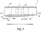
- FIG. 7 is a diagram schematically illustrating a configuration of the duct 2 according to one embodiment.
- FIG. 7 illustrates a cross-sectional view of the duct 2 taken along the extending direction of the duct 2.
- the configuration of the duct 2 illustrated in FIG. 7 may be applied to all of the plurality of ducts 2 or may be applied to some of the plurality of ducts 2.
- the configuration of the duct 2 illustrated in FIG. 7 may be applied to both of the one-side duct 10 and the other-side duct 12 described above.
- a duct 2 includes: an inlet section 50 forming an inlet 52 of the duct 2; an inlet-side flow channel 54 connected to the inlet section 50; an outlet section 56 forming an outlet 58 of the duct 2; an outlet-side flow channel 60 connected to the outlet section 56; and a propeller flow channel 62 connecting the inlet-side flow channel 54 and the outlet-side flow channel 60 and in which the propeller 4 is located.
- the inlet-side flow channel 54 includes a first section 64, and a second section 66 extending rearward from a trailing end 64a of the first section 64.
- the first section 64 the size of the flow channel cross section of the inlet-side flow channel 54 decreases toward the rear.
- the second section 66 is configured such that the size of the flow channel cross section of the inlet-side flow channel 54 is constant.
- the propeller flow channel 62 secures a space for arranging the propeller 4.
- the propeller flow channel 62 extends rearward from the trailing end 66a of the second section 66.
- the size of the flow channel cross section of the propeller flow channel 62 is substantially the same as the size of the flow channel cross section of the second section 66 of the inlet-side flow channel 54. Therefore, the flow channel cross section of the propeller flow channel 62 is smaller than that of the inlet-side flow channel 54. It should be noted that the propeller flow channel 62 has a circular flow channel cross section in order to effectively generate a propulsion force.
- the outlet-side flow channel 60 extends rearward from the trailing end 62a of the propeller flow channel 62. That is, the propeller flow channel 62 is located between the inlet-side flow channel 54 and the outlet-side flow channel 60 in the front-back direction.
- the size of the flow channel cross section of the outlet-side flow channel 60 is the same as the size of the flow channel cross section of the propeller flow channel 62.
- the wall thickness of the portion of the duct 2 where the propeller flow channel 62 is formed can be increased. Therefore, for example, it is possible to secure a space for arranging a motor for rotating the propeller 4 arranged in the propeller flow channel 62.
- the marine propulsor 1 further includes a contrarotating propeller 68 that is located inside the duct 2 and rotatable in the opposite direction to the rotational direction of the propeller 4.
- the contrarotating propeller 68 is located in the propeller flow channel 62. According to this configuration, the contrarotating propeller 68 generates a reverse flow of the propeller 4, and the propulsion efficiency of the marine propulsor 1 can be further improved by the double contrarotating effect.
- the outlet section 56 of the duct 2 is configured such that each of the outer periphery shape and the inner periphery shape has a quadrangular shape. According to such a configuration, resistance generated in the duct 2 can be reduced as compared with a case where the inner periphery shape of the outlet section 56 has a circular shape.
- the wall thickness of the outlet section 56 tends to be larger than when the inner periphery shape of the outlet section 56 has a quadrangular shape.
- the wall thickness of the outlet section 56 is large, the amount of resistance (loss) received by the fluid flowing out from the duct 2 also increases.
- each of the outer periphery shape and the inner periphery shape of the outlet section 56 in the duct 2 may be a polygonal shape, and is not limited to a quadrangular shape.
- a boundary layer is generated below the hull, where the flow velocity is slower than the movement velocity of the marine vessel, and friction resistance acts on the hull from the boundary layer.
- a side surface on the other side of the one-side duct is in contact with a side surface on the one side of the other-side duct.
- the boundary layer is prevented from flowing between the one-side duct and the other-side duct, and loss caused by the friction resistance acting on the hull from the boundary layer can be reduced. Therefore, the propulsion efficiency of the marine propulsor including the duct and the propeller rotatably disposed within the duct can be improved.
- each of the side surface of the one-side duct on the other side and the side surface of the other-side duct on the one side has a linear shape.
- each of the side surface of the one-side duct on the other side and the side surface of the other-side duct on the one side has a nonlinear shape (e.g., an arc shape).
- a top surface (18, 30) of each of the one-side duct and the other-side duct is in contact with a ship bottom area (108) of the hull.
- the boundary layer is suppressed from flowing between the one-side duct and the ship bottom area of the hull, and is suppressed from flowing between the other-side duct and the ship bottom area of the hull. Therefore, it is possible to further reduce a loss caused by friction resistance acting on the hull from the boundary layer.
- the plurality of ducts include three or more ducts arranged along the width direction of the hull, and for every pair of the ducts adjacent to each other in the width direction, the side surface of the one-side duct on the other side is in contact with the side surface of the other-side duct on the one side.
- the boundary layer is suppressed from flowing between the ducts adjacent to each other, and loss caused by the friction resistance acting on the hull from the boundary layer can be reduced.
- the one-side duct in the configuration described in any one of [1] to [4], is disposed such that an inlet section (14) forming an inlet (16) of the one-side duct is shifted from an inlet section (26) forming an inlet (28) of the other-side duct in a front-back direction of the hull.
- the hull includes a center skeg (110) protruding downward from the ship bottom area of the hull
- the plurality of ducts include: a first duct row (6) including a plurality of ducts arranged along the width direction of the hull and disposed on one side of the center skeg; and a second duct row (8) including a plurality of ducts arranged along the width direction of the hull and disposed on the other side of the center skeg, and center-side ducts (42, 44) that are closest to the center side in the width direction of the first duct row and the second duct row are respectively in contact with side surfaces of the center skeg.
- the boundary layer is suppressed from flowing between the center-side duct of the first duct row and the center skeg, and is suppressed from flowing between the center-side duct of the second duct row and the center skeg. Therefore, it is possible to further reduce a loss caused by friction resistance acting on the hull from the boundary layer.
- At least one duct among the plurality of ducts includes an inlet section (50) forming an inlet (52) of the at least one duct; an inlet-side flow channel (54) connected to the inlet section; an outlet section (56) forming an outlet (58) of the at least one duct; an outlet-side flow channel (60) connected to the outlet section; and a propeller flow channel (62) connecting the inlet-side flow channel and the outlet-side flow channel and in which the propeller is disposed, wherein the propeller flow channel has a smaller flow channel cross section than the inlet-side flow channel.
- the size of the flow channel cross section of the propeller flow channel is smaller than that of the inlet-side flow channel, it is possible to secure a space for arranging a device. For example, it is possible to secure a space for arranging a motor for rotating a propeller arranged in the propeller flow channel.
- a bottom surface (24, 36) of each of the plurality of ducts includes an inclined section (38, 40) inclined away from the ship bottom area of the hull toward the center side in the width direction.
- the boundary layer is inclined away from the ship bottom area of the hull toward the center side in the width direction. According to the configuration described in [8], the bottom surface of each of the plurality of ducts can be shaped along the boundary layer, and the propulsion efficiency of the marine propulsor can be further improved.
- the marine propulsor further includes a contrarotating propeller (68) located inside at least one of the plurality of ducts and rotatable in the opposite direction to the rotational direction of the propeller.
- the contrarotating propeller generates a reverse flow of the propeller, and the propulsion efficiency of the marine propulsor can be further improved by the double contrarotating effect.
- the propeller in the configuration described in any one of [1] to [9], includes: a rim (43) that is cylindrical and rotatably disposed inside each of the plurality of ducts; and a blade (45) surrounded by and fixed to the rim.
- a rim drive propulsion device that generates a propulsion force by rotating a cylindrical rim can be applied to the marine propulsor.
- a marine vessel includes the marine propulsor according to any one of [1] to [10].
Landscapes
- Chemical & Material Sciences (AREA)
- Engineering & Computer Science (AREA)
- Combustion & Propulsion (AREA)
- Mechanical Engineering (AREA)
- Ocean & Marine Engineering (AREA)
- Rigid Pipes And Flexible Pipes (AREA)
- Duct Arrangements (AREA)
Applications Claiming Priority (1)
| Application Number | Priority Date | Filing Date | Title |
|---|---|---|---|
| JP2021041044A JP2022140948A (ja) | 2021-03-15 | 2021-03-15 | 船舶推進装置、船舶 |
Publications (3)
| Publication Number | Publication Date |
|---|---|
| EP4059830A2 true EP4059830A2 (de) | 2022-09-21 |
| EP4059830A3 EP4059830A3 (de) | 2022-10-12 |
| EP4059830B1 EP4059830B1 (de) | 2026-08-05 |
Family
ID=80595307
Family Applications (1)
| Application Number | Title | Priority Date | Filing Date |
|---|---|---|---|
| EP22159192.8A Active EP4059830B1 (de) | 2021-03-15 | 2022-02-28 | Schiffsantrieb, wasserfahrzeug |
Country Status (2)
| Country | Link |
|---|---|
| EP (1) | EP4059830B1 (de) |
| JP (1) | JP2022140948A (de) |
Cited By (1)
| Publication number | Priority date | Publication date | Assignee | Title |
|---|---|---|---|---|
| WO2023281548A1 (en) * | 2021-07-06 | 2023-01-12 | Nablawave S.R.L. | Boat and propulsion device for boats |
Citations (1)
| Publication number | Priority date | Publication date | Assignee | Title |
|---|---|---|---|---|
| JP2013503784A (ja) | 2009-09-08 | 2013-02-04 | テヒニッシェ ウニヴェルズィテート ハンブルク−ハーブルク | 高い効率を有する、機械的に駆動されるボスレス式の船舶推進装置 |
Family Cites Families (4)
| Publication number | Priority date | Publication date | Assignee | Title |
|---|---|---|---|---|
| DE426521C (de) * | 1927-01-28 | Rudolf Wagner Dr | Ganz oder teilweise den Schraubenstrom einhuellender Leitmantel | |
| DE2640077A1 (de) * | 1976-09-06 | 1978-03-16 | Ruediger Staege | Saugverdraenger (schiffstyp) |
| JP5582761B2 (ja) * | 2009-11-09 | 2014-09-03 | 三菱重工業株式会社 | 船舶の推進装置 |
| US8881666B2 (en) * | 2012-08-10 | 2014-11-11 | Si Co. Ltd. | Ship |
-
2021
- 2021-03-15 JP JP2021041044A patent/JP2022140948A/ja active Pending
-
2022
- 2022-02-28 EP EP22159192.8A patent/EP4059830B1/de active Active
Patent Citations (1)
| Publication number | Priority date | Publication date | Assignee | Title |
|---|---|---|---|---|
| JP2013503784A (ja) | 2009-09-08 | 2013-02-04 | テヒニッシェ ウニヴェルズィテート ハンブルク−ハーブルク | 高い効率を有する、機械的に駆動されるボスレス式の船舶推進装置 |
Cited By (1)
| Publication number | Priority date | Publication date | Assignee | Title |
|---|---|---|---|---|
| WO2023281548A1 (en) * | 2021-07-06 | 2023-01-12 | Nablawave S.R.L. | Boat and propulsion device for boats |
Also Published As
| Publication number | Publication date |
|---|---|
| JP2022140948A (ja) | 2022-09-29 |
| EP4059830A3 (de) | 2022-10-12 |
| EP4059830B1 (de) | 2026-08-05 |
Similar Documents
| Publication | Publication Date | Title |
|---|---|---|
| CN105980246B (zh) | 操舵装置 | |
| EP2163472B1 (de) | Antriebs- und Steueranordnung | |
| KR20010006339A (ko) | 유체 이동 블래이드 | |
| US20110073029A1 (en) | Tunnel thruster for vessels | |
| US9322290B2 (en) | Propeller nozzle | |
| JP4789953B2 (ja) | 船舶用推進システム | |
| JP7149660B1 (ja) | 船舶舵 | |
| US10703453B2 (en) | Marine vessel | |
| EP1280694B1 (de) | Bootskörper-propeller-anordnung | |
| JPH085431B2 (ja) | 舶用推進装置 | |
| KR101225169B1 (ko) | 추진장치 및 이를 구비한 선박 | |
| JP2022140948A (ja) | 船舶推進装置、船舶 | |
| KR20160150222A (ko) | 선박 추진장치 | |
| JP2012131475A (ja) | 船舶用舵 | |
| US20070028824A1 (en) | Boat control system | |
| JP2013043632A (ja) | 船舶の非対称ねじれ流動制御フィン | |
| EP1931564B1 (de) | Schiffsantriebssystem mit teilweise eingetauchtem propeller | |
| US7316194B1 (en) | Rudders for high-speed ships | |
| US11981410B2 (en) | Stern bulbs | |
| JP7860840B2 (ja) | サイドスラスタ装置 | |
| KR101323795B1 (ko) | 선박 | |
| JPS58491A (ja) | 船舶推進性能向上装置 | |
| CN87105375A (zh) | 船舶 | |
| JP2022147294A (ja) | 船舶推進装置、船舶 | |
| JP2024053807A (ja) | 船舶推進装置 |
Legal Events
| Date | Code | Title | Description |
|---|---|---|---|
| PUAI | Public reference made under article 153(3) epc to a published international application that has entered the european phase |
Free format text: ORIGINAL CODE: 0009012 |
|
| STAA | Information on the status of an ep patent application or granted ep patent |
Free format text: STATUS: THE APPLICATION HAS BEEN PUBLISHED |
|
| PUAL | Search report despatched |
Free format text: ORIGINAL CODE: 0009013 |
|
| AK | Designated contracting states |
Kind code of ref document: A2 Designated state(s): AL AT BE BG CH CY CZ DE DK EE ES FI FR GB GR HR HU IE IS IT LI LT LU LV MC MK MT NL NO PL PT RO RS SE SI SK SM TR |
|
| AK | Designated contracting states |
Kind code of ref document: A3 Designated state(s): AL AT BE BG CH CY CZ DE DK EE ES FI FR GB GR HR HU IE IS IT LI LT LU LV MC MK MT NL NO PL PT RO RS SE SI SK SM TR |
|
| RIC1 | Information provided on ipc code assigned before grant |
Ipc: B63H 5/16 20060101ALI20220902BHEP Ipc: B63H 5/14 20060101ALI20220902BHEP Ipc: B63H 5/08 20060101AFI20220902BHEP |
|
| STAA | Information on the status of an ep patent application or granted ep patent |
Free format text: STATUS: REQUEST FOR EXAMINATION WAS MADE |
|
| 17P | Request for examination filed |
Effective date: 20230130 |
|
| RBV | Designated contracting states (corrected) |
Designated state(s): AL AT BE BG CH CY CZ DE DK EE ES FI FR GB GR HR HU IE IS IT LI LT LU LV MC MK MT NL NO PL PT RO RS SE SI SK SM TR |
|
| STAA | Information on the status of an ep patent application or granted ep patent |
Free format text: STATUS: EXAMINATION IS IN PROGRESS |
|
| 17Q | First examination report despatched |
Effective date: 20241209 |
|
| GRAP | Despatch of communication of intention to grant a patent |
Free format text: ORIGINAL CODE: EPIDOSNIGR1 |
|
| STAA | Information on the status of an ep patent application or granted ep patent |
Free format text: STATUS: GRANT OF PATENT IS INTENDED |
|
| INTG | Intention to grant announced |
Effective date: 20260303 |
|
| GRAS | Grant fee paid |
Free format text: ORIGINAL CODE: EPIDOSNIGR3 |
|
| GRAA | (expected) grant |
Free format text: ORIGINAL CODE: 0009210 |
|
| STAA | Information on the status of an ep patent application or granted ep patent |
Free format text: STATUS: THE PATENT HAS BEEN GRANTED |
|
| AK | Designated contracting states |
Kind code of ref document: B1 Designated state(s): AL AT BE BG CH CY CZ DE DK EE ES FI FR GB GR HR HU IE IS IT LI LT LU LV MC MK MT NL NO PL PT RO RS SE SI SK SM TR |
|
| REG | Reference to a national code |
Ref country code: CH Ref legal event code: F10 Free format text: ST27 STATUS EVENT CODE: U-0-0-F10-F00 (AS PROVIDED BY THE NATIONAL OFFICE) Effective date: 20260805 |