EP4059846A1 - Lagerstromabschwächung für eine in einer gasturbine eingebettete elektrische maschine - Google Patents
Lagerstromabschwächung für eine in einer gasturbine eingebettete elektrische maschine Download PDFInfo
- Publication number
- EP4059846A1 EP4059846A1 EP22157192.0A EP22157192A EP4059846A1 EP 4059846 A1 EP4059846 A1 EP 4059846A1 EP 22157192 A EP22157192 A EP 22157192A EP 4059846 A1 EP4059846 A1 EP 4059846A1
- Authority
- EP
- European Patent Office
- Prior art keywords
- rotor
- shaft
- electric machine
- electric
- hybrid
- Prior art date
- Legal status (The legal status is an assumption and is not a legal conclusion. Google has not performed a legal analysis and makes no representation as to the accuracy of the status listed.)
- Granted
Links
Images







Classifications
-
- B—PERFORMING OPERATIONS; TRANSPORTING
- B64—AIRCRAFT; AVIATION; COSMONAUTICS
- B64D—EQUIPMENT FOR FITTING IN OR TO AIRCRAFT; FLIGHT SUITS; PARACHUTES; ARRANGEMENT OR MOUNTING OF POWER PLANTS OR PROPULSION TRANSMISSIONS IN AIRCRAFT
- B64D33/00—Arrangement in aircraft of power plant parts or auxiliaries not otherwise provided for
-
- B—PERFORMING OPERATIONS; TRANSPORTING
- B64—AIRCRAFT; AVIATION; COSMONAUTICS
- B64D—EQUIPMENT FOR FITTING IN OR TO AIRCRAFT; FLIGHT SUITS; PARACHUTES; ARRANGEMENT OR MOUNTING OF POWER PLANTS OR PROPULSION TRANSMISSIONS IN AIRCRAFT
- B64D27/00—Arrangement or mounting of power plants in aircraft; Aircraft characterised by the type or position of power plants
- B64D27/02—Aircraft characterised by the type or position of power plants
- B64D27/30—Aircraft characterised by electric power plants
- B64D27/33—Hybrid electric aircraft
-
- B—PERFORMING OPERATIONS; TRANSPORTING
- B64—AIRCRAFT; AVIATION; COSMONAUTICS
- B64D—EQUIPMENT FOR FITTING IN OR TO AIRCRAFT; FLIGHT SUITS; PARACHUTES; ARRANGEMENT OR MOUNTING OF POWER PLANTS OR PROPULSION TRANSMISSIONS IN AIRCRAFT
- B64D27/00—Arrangement or mounting of power plants in aircraft; Aircraft characterised by the type or position of power plants
- B64D27/02—Aircraft characterised by the type or position of power plants
- B64D27/30—Aircraft characterised by electric power plants
- B64D27/35—Arrangements for on-board electric energy production, distribution, recovery or storage
- B64D27/351—Arrangements for on-board electric energy production, distribution, recovery or storage using energy recovery
-
- B—PERFORMING OPERATIONS; TRANSPORTING
- B64—AIRCRAFT; AVIATION; COSMONAUTICS
- B64D—EQUIPMENT FOR FITTING IN OR TO AIRCRAFT; FLIGHT SUITS; PARACHUTES; ARRANGEMENT OR MOUNTING OF POWER PLANTS OR PROPULSION TRANSMISSIONS IN AIRCRAFT
- B64D35/00—Transmitting power from power plants to propellers or rotors; Arrangements of transmissions
- B64D35/02—Transmitting power from power plants to propellers or rotors; Arrangements of transmissions specially adapted for specific power plants
- B64D35/021—Transmitting power from power plants to propellers or rotors; Arrangements of transmissions specially adapted for specific power plants for electric power plants
- B64D35/022—Transmitting power from power plants to propellers or rotors; Arrangements of transmissions specially adapted for specific power plants for electric power plants of hybrid-electric type
- B64D35/024—Transmitting power from power plants to propellers or rotors; Arrangements of transmissions specially adapted for specific power plants for electric power plants of hybrid-electric type of series type
-
- F—MECHANICAL ENGINEERING; LIGHTING; HEATING; WEAPONS; BLASTING
- F02—COMBUSTION ENGINES; HOT-GAS OR COMBUSTION-PRODUCT ENGINE PLANTS
- F02C—GAS-TURBINE PLANTS; AIR INTAKES FOR JET-PROPULSION PLANTS; CONTROLLING FUEL SUPPLY IN AIR-BREATHING JET-PROPULSION PLANTS
- F02C6/00—Plural gas-turbine plants; Combinations of gas-turbine plants with other apparatus; Adaptations of gas-turbine plants for special use
- F02C6/20—Adaptations of gas-turbine plants for driving vehicles
- F02C6/206—Adaptations of gas-turbine plants for driving vehicles the vehicles being airscrew driven
-
- F—MECHANICAL ENGINEERING; LIGHTING; HEATING; WEAPONS; BLASTING
- F02—COMBUSTION ENGINES; HOT-GAS OR COMBUSTION-PRODUCT ENGINE PLANTS
- F02C—GAS-TURBINE PLANTS; AIR INTAKES FOR JET-PROPULSION PLANTS; CONTROLLING FUEL SUPPLY IN AIR-BREATHING JET-PROPULSION PLANTS
- F02C7/00—Features, components parts, details or accessories, not provided for in, or of interest apart form groups F02C1/00 - F02C6/00; Air intakes for jet-propulsion plants
- F02C7/06—Arrangements of bearings; Lubricating
-
- F—MECHANICAL ENGINEERING; LIGHTING; HEATING; WEAPONS; BLASTING
- F02—COMBUSTION ENGINES; HOT-GAS OR COMBUSTION-PRODUCT ENGINE PLANTS
- F02C—GAS-TURBINE PLANTS; AIR INTAKES FOR JET-PROPULSION PLANTS; CONTROLLING FUEL SUPPLY IN AIR-BREATHING JET-PROPULSION PLANTS
- F02C7/00—Features, components parts, details or accessories, not provided for in, or of interest apart form groups F02C1/00 - F02C6/00; Air intakes for jet-propulsion plants
- F02C7/32—Arrangement, mounting, or driving, of auxiliaries
-
- F—MECHANICAL ENGINEERING; LIGHTING; HEATING; WEAPONS; BLASTING
- F02—COMBUSTION ENGINES; HOT-GAS OR COMBUSTION-PRODUCT ENGINE PLANTS
- F02K—JET-PROPULSION PLANTS
- F02K1/00—Plants characterised by the form or arrangement of the jet pipe or nozzle; Jet pipes or nozzles peculiar thereto
- F02K1/04—Mounting of an exhaust cone in the jet pipe
-
- H—ELECTRICITY
- H02—GENERATION; CONVERSION OR DISTRIBUTION OF ELECTRIC POWER
- H02K—DYNAMO-ELECTRIC MACHINES
- H02K1/00—Details of the magnetic circuit
- H02K1/06—Details of the magnetic circuit characterised by the shape, form or construction
- H02K1/22—Rotating parts of the magnetic circuit
- H02K1/27—Rotor cores with permanent magnets
- H02K1/2786—Outer rotors
-
- H—ELECTRICITY
- H02—GENERATION; CONVERSION OR DISTRIBUTION OF ELECTRIC POWER
- H02K—DYNAMO-ELECTRIC MACHINES
- H02K11/00—Structural association of dynamo-electric machines with electric components or with devices for shielding, monitoring or protection
- H02K11/02—Structural association of dynamo-electric machines with electric components or with devices for shielding, monitoring or protection for suppression of electromagnetic interference
-
- H—ELECTRICITY
- H02—GENERATION; CONVERSION OR DISTRIBUTION OF ELECTRIC POWER
- H02K—DYNAMO-ELECTRIC MACHINES
- H02K11/00—Structural association of dynamo-electric machines with electric components or with devices for shielding, monitoring or protection
- H02K11/20—Structural association of dynamo-electric machines with electric components or with devices for shielding, monitoring or protection for measuring, monitoring, testing, protecting or switching
- H02K11/21—Devices for sensing speed or position, or actuated thereby
-
- H—ELECTRICITY
- H02—GENERATION; CONVERSION OR DISTRIBUTION OF ELECTRIC POWER
- H02K—DYNAMO-ELECTRIC MACHINES
- H02K11/00—Structural association of dynamo-electric machines with electric components or with devices for shielding, monitoring or protection
- H02K11/40—Structural association with grounding devices
-
- H—ELECTRICITY
- H02—GENERATION; CONVERSION OR DISTRIBUTION OF ELECTRIC POWER
- H02K—DYNAMO-ELECTRIC MACHINES
- H02K24/00—Machines adapted for the instantaneous transmission or reception of the angular displacement of rotating parts, e.g. synchro, selsyn
-
- H—ELECTRICITY
- H02—GENERATION; CONVERSION OR DISTRIBUTION OF ELECTRIC POWER
- H02K—DYNAMO-ELECTRIC MACHINES
- H02K7/00—Arrangements for handling mechanical energy structurally associated with dynamo-electric machines, e.g. structural association with mechanical driving motors or auxiliary dynamo-electric machines
- H02K7/003—Couplings; Details of shafts
-
- H—ELECTRICITY
- H02—GENERATION; CONVERSION OR DISTRIBUTION OF ELECTRIC POWER
- H02K—DYNAMO-ELECTRIC MACHINES
- H02K7/00—Arrangements for handling mechanical energy structurally associated with dynamo-electric machines, e.g. structural association with mechanical driving motors or auxiliary dynamo-electric machines
- H02K7/08—Structural association with bearings
-
- H—ELECTRICITY
- H02—GENERATION; CONVERSION OR DISTRIBUTION OF ELECTRIC POWER
- H02K—DYNAMO-ELECTRIC MACHINES
- H02K7/00—Arrangements for handling mechanical energy structurally associated with dynamo-electric machines, e.g. structural association with mechanical driving motors or auxiliary dynamo-electric machines
- H02K7/18—Structural association of electric generators with mechanical driving motors, e.g. with turbines
- H02K7/1807—Rotary generators
- H02K7/1823—Rotary generators structurally associated with turbines or similar engines
-
- H—ELECTRICITY
- H03—ELECTRONIC CIRCUITRY
- H03H—IMPEDANCE NETWORKS, e.g. RESONANT CIRCUITS; RESONATORS
- H03H1/00—Constructional details of impedance networks whose electrical mode of operation is not specified or applicable to more than one type of network
- H03H1/0007—Constructional details of impedance networks whose electrical mode of operation is not specified or applicable to more than one type of network of radio frequency interference filters
-
- B—PERFORMING OPERATIONS; TRANSPORTING
- B64—AIRCRAFT; AVIATION; COSMONAUTICS
- B64D—EQUIPMENT FOR FITTING IN OR TO AIRCRAFT; FLIGHT SUITS; PARACHUTES; ARRANGEMENT OR MOUNTING OF POWER PLANTS OR PROPULSION TRANSMISSIONS IN AIRCRAFT
- B64D27/00—Arrangement or mounting of power plants in aircraft; Aircraft characterised by the type or position of power plants
- B64D27/02—Aircraft characterised by the type or position of power plants
- B64D27/30—Aircraft characterised by electric power plants
- B64D27/31—Aircraft characterised by electric power plants within, or attached to, wings
-
- B—PERFORMING OPERATIONS; TRANSPORTING
- B64—AIRCRAFT; AVIATION; COSMONAUTICS
- B64D—EQUIPMENT FOR FITTING IN OR TO AIRCRAFT; FLIGHT SUITS; PARACHUTES; ARRANGEMENT OR MOUNTING OF POWER PLANTS OR PROPULSION TRANSMISSIONS IN AIRCRAFT
- B64D27/00—Arrangement or mounting of power plants in aircraft; Aircraft characterised by the type or position of power plants
- B64D27/02—Aircraft characterised by the type or position of power plants
- B64D27/30—Aircraft characterised by electric power plants
- B64D27/35—Arrangements for on-board electric energy production, distribution, recovery or storage
- B64D27/357—Arrangements for on-board electric energy production, distribution, recovery or storage using batteries
-
- B—PERFORMING OPERATIONS; TRANSPORTING
- B64—AIRCRAFT; AVIATION; COSMONAUTICS
- B64D—EQUIPMENT FOR FITTING IN OR TO AIRCRAFT; FLIGHT SUITS; PARACHUTES; ARRANGEMENT OR MOUNTING OF POWER PLANTS OR PROPULSION TRANSMISSIONS IN AIRCRAFT
- B64D27/00—Arrangement or mounting of power plants in aircraft; Aircraft characterised by the type or position of power plants
- B64D27/02—Aircraft characterised by the type or position of power plants
- B64D27/30—Aircraft characterised by electric power plants
- B64D27/35—Arrangements for on-board electric energy production, distribution, recovery or storage
- B64D27/359—Arrangements for on-board electric energy production, distribution, recovery or storage using capacitors
-
- F—MECHANICAL ENGINEERING; LIGHTING; HEATING; WEAPONS; BLASTING
- F05—INDEXING SCHEMES RELATING TO ENGINES OR PUMPS IN VARIOUS SUBCLASSES OF CLASSES F01-F04
- F05D—INDEXING SCHEME FOR ASPECTS RELATING TO NON-POSITIVE-DISPLACEMENT MACHINES OR ENGINES, GAS-TURBINES OR JET-PROPULSION PLANTS
- F05D2220/00—Application
- F05D2220/30—Application in turbines
- F05D2220/32—Application in turbines in gas turbines
- F05D2220/323—Application in turbines in gas turbines for aircraft propulsion, e.g. jet engines
-
- F—MECHANICAL ENGINEERING; LIGHTING; HEATING; WEAPONS; BLASTING
- F05—INDEXING SCHEMES RELATING TO ENGINES OR PUMPS IN VARIOUS SUBCLASSES OF CLASSES F01-F04
- F05D—INDEXING SCHEME FOR ASPECTS RELATING TO NON-POSITIVE-DISPLACEMENT MACHINES OR ENGINES, GAS-TURBINES OR JET-PROPULSION PLANTS
- F05D2220/00—Application
- F05D2220/70—Application in combination with
- F05D2220/76—Application in combination with an electrical generator
-
- F—MECHANICAL ENGINEERING; LIGHTING; HEATING; WEAPONS; BLASTING
- F05—INDEXING SCHEMES RELATING TO ENGINES OR PUMPS IN VARIOUS SUBCLASSES OF CLASSES F01-F04
- F05D—INDEXING SCHEME FOR ASPECTS RELATING TO NON-POSITIVE-DISPLACEMENT MACHINES OR ENGINES, GAS-TURBINES OR JET-PROPULSION PLANTS
- F05D2220/00—Application
- F05D2220/70—Application in combination with
- F05D2220/76—Application in combination with an electrical generator
- F05D2220/766—Application in combination with an electrical generator via a direct connection, i.e. a gearless transmission
-
- F—MECHANICAL ENGINEERING; LIGHTING; HEATING; WEAPONS; BLASTING
- F05—INDEXING SCHEMES RELATING TO ENGINES OR PUMPS IN VARIOUS SUBCLASSES OF CLASSES F01-F04
- F05D—INDEXING SCHEME FOR ASPECTS RELATING TO NON-POSITIVE-DISPLACEMENT MACHINES OR ENGINES, GAS-TURBINES OR JET-PROPULSION PLANTS
- F05D2260/00—Function
- F05D2260/30—Retaining components in desired mutual position
- F05D2260/31—Retaining bolts or nuts
-
- Y—GENERAL TAGGING OF NEW TECHNOLOGICAL DEVELOPMENTS; GENERAL TAGGING OF CROSS-SECTIONAL TECHNOLOGIES SPANNING OVER SEVERAL SECTIONS OF THE IPC; TECHNICAL SUBJECTS COVERED BY FORMER USPC CROSS-REFERENCE ART COLLECTIONS [XRACs] AND DIGESTS
- Y02—TECHNOLOGIES OR APPLICATIONS FOR MITIGATION OR ADAPTATION AGAINST CLIMATE CHANGE
- Y02T—CLIMATE CHANGE MITIGATION TECHNOLOGIES RELATED TO TRANSPORTATION
- Y02T50/00—Aeronautics or air transport
- Y02T50/60—Efficient propulsion technologies, e.g. for aircraft
Definitions
- the present subject matter relates generally to gas turbine engines equipped with embedded electric machines.
- a conventional commercial aircraft generally includes a fuselage, a pair of wings, and a propulsion system that provides thrust.
- the propulsion system typically includes at least two aircraft engines, such as turbofan jet engines.
- Each turbofan jet engine is typically mounted to a respective one of the wings of the aircraft, such as in a suspended position beneath the wing separated from the wing and fuselage.
- Hybrid-electric propulsion systems are being developed to improve an efficiency of conventional commercial aircraft.
- Some hybrid electric propulsion systems include one or more electric machines each being operatively coupled with a rotating component of one of the aircraft engines.
- the inventors of the present disclosure have developed various configurations and/or methods to improve hybrid electric propulsion systems.
- a hybrid-electric propulsion system in one exemplary aspect of the present disclosure, includes a power converter and a propulsor.
- the propulsor includes a gas turbine engine having a shaft and one or more bearings supporting the shaft. Further, the propulsor includes an electric machine electrically coupled with the power converter.
- the electric machine includes a stator assembly and a rotor assembly.
- the rotor assembly has a rotor and a rotor connection assembly.
- the rotor connection assembly operatively couples the rotor with the shaft.
- the rotor connection assembly has an insulated joint for interrupting common mode electric current from flowing from the rotor to the shaft.
- a grounding device may be included to electrically ground the shaft.
- first, second, and third may be used interchangeably to distinguish one component from another and are not intended to signify location or importance of the individual components.
- forward and aft refer to relative positions within a gas turbine engine or vehicle, and refer to the normal operational attitude of the gas turbine engine or vehicle.
- forward refers to a position closer to an engine inlet and aft refers to a position closer to an engine nozzle or exhaust.
- upstream and downstream refer to the relative direction with respect to a flow in a pathway.
- upstream refers to the direction from which the fluid flows
- downstream refers to the direction to which the fluid flows.
- upstream and downstream as used herein may also refer to a flow of electricity.
- Approximating language is applied to modify any quantitative representation that could permissibly vary without resulting in a change in the basic function to which it is related. Accordingly, a value modified by a term or terms, such as “about”, “approximately”, and “substantially”, are not to be limited to the precise value specified.
- the approximating language may correspond to the precision of an instrument for measuring the value, or the precision of the methods or machines for constructing or manufacturing the components and/or systems.
- the approximating language may correspond to the precision of an instrument for measuring the value, or the precision of the methods or machines for constructing or manufacturing the components and/or systems.
- the approximating language may refer to being within a 1, 2, 4, 5, 10, 15, or 20 percent margin in either individual values, range(s) of values and/or endpoints defining range(s) of values.
- common mode voltages can be produced by sinusoidal power supplies, such as power converter supplies.
- an electric machine connected to a power converter supply is inherently subject to common mode voltages.
- Such common mode voltages can induce or drive electric currents in the bearings supporting the shaft to which the electric machine is coupled.
- Electric currents in bearings can cause pitting of bearing elements, such as the balls, rollers, races, etc., and consequently, premature failures of such bearings can occur. Accordingly, mitigation of such bearing electric currents is desirable.
- Some conventional techniques for mitigating bearing currents in electric machines connected to power converters involve using ceramic bearings to support the shaft to which the electric machine is coupled. While such ceramic bearings are effective, in some instances, the use of ceramic bearings is not a viable option, e.g., when the bearings are shared with other components. Further, grounding brushes have been conventionally used in addition to ceramic bearings. However, like ceramic bearings, in some instances grounding brushes may not be allowed.
- the bearing electric current mitigation solutions developed by the inventors of the present disclosure provide alternative solutions to such conventional techniques.
- a three-prong solution can be implemented.
- the three-prong solution can include 1) reducing the common mode voltage reaching the electric machine from the power converter connected thereto; 2) interrupting the common mode current conductive path between the rotor of the electric machine and the shaft to which it is coupled; and 3) grounding at least one of the members connecting the rotor of the electric machine and the shaft.
- an electromagnetic interference filter of a power converter electrically coupled with the electric machine can reduce the common mode voltage reaching the electric machine.
- shielded cables or shielded bus bars electrically coupling the power converter and the electric machine can be used to further reduce the common mode voltage reaching the electric machine.
- a rotor connection assembly coupling the rotor of the electric machine with the shaft can include an insulated joint.
- the insulated joint includes one or more insulative members strategically arranged to interrupt common mode electric current from flowing to the shaft.
- a grounding device is positioned relative to the shaft or a component rotatable with the shaft to electrically ground the shaft. The grounding device can be integrated into an existing component of the engine.
- the grounding device can be integrated into a resolver, an encoder, or an existing seal, such as a carbon seal or a brush seal.
- bearing electric current mitigation can be achieved.
- this may enable achieving a specific fuel burn gain through the circulation of electric power between low speed and high speed spools without shortening the life of bearings supporting the spools.
- this may enable mitigating the low speed bearing currents without modification of such bearings and with only minimal modification to the spool rotor structure.
- FIG. 1 provides a schematic top view of an exemplary aircraft 100 as may incorporate one or more inventive aspects of the present disclosure.
- the aircraft 100 defines a longitudinal direction L1 and a lateral direction L2.
- the lateral direction L2 is perpendicular to the longitudinal direction L1.
- the aircraft 100 also defines a longitudinal centerline 114 that extends therethrough along the longitudinal direction L1.
- the aircraft 100 extends between a forward end 116 and an aft end 118, e.g., along the longitudinal direction L1.
- the aircraft 100 includes a fuselage 112 that extends longitudinally from the forward end 116 of the aircraft 100 to the aft end 118 of the aircraft 100.
- the aircraft 100 also includes an empennage 119 at the aft end 118 of the aircraft 100.
- the aircraft 100 includes a wing assembly including a first, port side wing 120 and a second, starboard side wing 122.
- the first and second wings 120, 122 each extend laterally outward with respect to the longitudinal centerline 114.
- the first wing 120 and a portion of the fuselage 112 together define a first side 124 of the aircraft 100 and the second wing 122 and another portion of the fuselage 112 together define a second side 126 of the aircraft 100.
- the first side 124 of the aircraft 100 is configured as the port side of the aircraft 100 and the second side 126 of the aircraft 100 is configured as the starboard side of the aircraft 100.
- each wing 120, 122 includes one or more leading edge flaps 128 and one or more trailing edge flaps 130.
- the aircraft 100 further includes, or more specifically, the empennage 119 of the aircraft 100 includes a vertical stabilizer 132 having a rudder flap (not shown) for yaw control and a pair of horizontal stabilizers 134 each having an elevator flap 136 for pitch control.
- the fuselage 112 additionally includes an outer surface or skin 138. It should be appreciated that in other exemplary embodiments of the present disclosure, the aircraft 100 may additionally or alternatively include any other suitable configuration. For example, in other embodiments, the aircraft 100 may include any other control surface configuration.
- the exemplary aircraft 100 of FIG. 1 also includes a hybrid-electric propulsion system 150.
- the hybrid-electric propulsion system 150 has a first propulsor 200A and a second propulsor 200B both operable to produce thrust.
- the first propulsor 200A is mounted to the first wing 120 and the second propulsor 200B is mounted to the second wing 122.
- the first propulsor 200A and second propulsor 200B are each configured in an underwing-mounted configuration.
- one or both of the first and second propulsors 200A, 200B may be mounted at any other suitable location in other exemplary embodiments.
- the first propulsor 200A includes a gas turbine engine 210A and one or more electric machines, such as electric machine 300A operatively coupled with the gas turbine engine 210A.
- the electric machine 300A can be an electric generator, an electric motor, or a combination generator/motor.
- the electric machine 300A is a combination generator/motor. In this manner, when operating as an electric generator, the electric machine 300A can generate electrical power when driven by the gas turbine engine 210A. When operating as an electric motor, the electric machine 300A can drive or motor the gas turbine engine 210A.
- the second propulsor 200B includes a gas turbine engine 210B and one or more electric machines, such as electric machine 300B operatively coupled with the gas turbine engine 210B.
- the electric machine 300B can be an electric generator, an electric motor, or a combination generator/motor.
- the electric machine 300B is a combination generator/motor.
- the electric machine 300B can generate electrical power when driven by the gas turbine engine 210B.
- the electric machine 300B can drive or motor a spool of the gas turbine engine 210B.
- Electric machine 300B can be configured and can operate in a similar manner as electric machine 300A described herein.
- the hybrid-electric propulsion system 150 further includes an electric energy storage unit 180 (only one shown in FIG. 1 ) electrically connectable to the electric machines 300A, 300B, and in some embodiments, other electrical loads.
- the electric energy storage unit 180 may include one or more batteries. Additionally, or alternatively, the electric energy storage units 180 may include one or more supercapacitor arrays, one or more ultracapacitor arrays, or both.
- the electric energy storage unit 180 is configured to store a relatively large amount of electrical power.
- the electric energy storage unit 180 may be configured to store at least about fifty kilowatt hours of electrical power, such as at least about sixty-five kilowatt hours of electrical power, such as at least about seventy-five kilowatts hours of electrical power, and up to about one thousand kilowatt hours of electrical power.
- the hybrid-electric propulsion system 150 also includes a power management system having a controller 182 and a power bus 184.
- the electric machines 300A, 300B, the electric energy storage unit 180, and the controller 182 are each electrically connectable to one another through one or more electric lines 186 of the power bus 184.
- the power bus 184 may include various switches or other power electronics movable to selectively electrically connect the various components of the hybrid-electric propulsion system 150. Particularly, as shown in FIG.
- a first power converter 188A of the power bus 184 is electrically coupled or connectable with the electric machine 300A via one or more electric lines 186 and a second power converter 188B of the power bus 184 is electrically coupled or connectable with the electric machine 300B via one or more electric lines 186.
- the power bus 184 may include other power electronics, such as inverters, converters, rectifiers, etc., for conditioning or converting electrical power within the hybrid-electric propulsion system 150.
- the controller 182 is configured to control the power electronics to distribute electrical power between the various components of the hybrid-electric propulsion system 150.
- the controller 182 may control the power electronics of the power bus 184 to provide electrical power to, or draw electrical power from, the various components, such as the electric machines 300A, 300B, to operate the hybrid-electric propulsion system 150 between various operating modes and perform various functions.
- the electric lines 186 of the power bus 184 extend through the controller 182.
- the controller 182 can form a part of a computing system 190 of the aircraft 100.
- the computing system 190 of the aircraft 100 can include one or more processors and one or more memory devices embodied in one or more computing devices.
- the computing system 190 includes controller 182 as well as other computing devices, such as computing device 192.
- the computing system 190 can include other computing devices as well, such as engine controllers (not shown).
- the computing devices of the computing system 190 can be communicatively coupled with one another via a communication network.
- computing device 192 is located in the cockpit of the aircraft 100 and is communicatively coupled with the controller 182 of the hybrid-electric propulsion system 150 via a communication link 194 of the communication network.
- the communication link 194 can include one or more wired or wireless communication links.
- the computing device 192 is configured to receive and process inputs, e.g., from a pilot or other crew members, and/or other information.
- the one or more processors of the computing device 192 can receive an input indicating a command to change a thrust output of the first and/or second propulsors 200A, 200B and can cause, in response to the input, the controller 182 to control the electrical power drawn from or delivered to one or both of the electric machines 300A, 300B to ultimately change the thrust output of one or both of the propulsors 200A, 200B.
- the controller 182 and other computing devices of the computing system 190 of the aircraft 100 may be configured in substantially the same manner as the exemplary computing devices of the computing system 700 described below with reference to FIG. 15 (and may be configured to perform one or more of the functions of the exemplary method (600) described below).
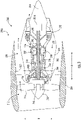
- FIG. 2 provides a schematic view of the first propulsor 200A of the hybrid-electric propulsion system 150 of the aircraft 100 of FIG. 1 .
- the exemplary gas turbine engine of FIG. 2 is configured as a single unducted rotor engine 210A defining an axial direction A, a radial direction R, and a circumferential direction C.
- the engine 210A also defines a central longitudinal axis 214.
- the engine 210A takes the form of an open rotor propulsion system and has a rotor assembly 212 that includes an array of airfoils arranged around the central longitudinal axis 214 of engine 210A. More particularly, the rotor assembly 212 includes an array of rotor blades 216 arranged around the central longitudinal axis 214 of the engine 210A. Moreover, as will be explained in more detail below, the engine 210A also includes a non-rotating vane assembly 218 positioned aft of the rotor assembly 212 (i.e., non-rotating with respect to the central axis 214). The non-rotating vane assembly 218 includes an array of airfoils also disposed around central axis 214. More specifically, the vane assembly 218 includes an array of vanes 220 disposed around central longitudinal axis 214.
- the rotor blades 216 are arranged in typically equally-spaced relation around the central longitudinal axis 214, and each blade has a root 222 and a tip 224 and a span defined therebetween.
- the vanes 220 are also arranged in typically equally-spaced relation around the central longitudinal axis 214, and each has a root 226 and a tip 228 and a span defined therebetween.
- the rotor assembly 212 further includes a hub 245 located forward of the plurality of rotor blades 216.
- the engine 210A includes a turbomachine 230 having a core (or high pressure/ high speed system) 232 and a low pressure/ low speed system.
- a turbomachine 230 having a core (or high pressure/ high speed system) 232 and a low pressure/ low speed system.
- the core 232 generally includes a high speed compressor 234, a high speed turbine 236, and a high speed shaft 238 extending therebetween and connecting the high speed compressor 234 and high speed turbine 236.
- the high speed compressor 234, the high speed turbine 236, and the high speed shaft 238 may collectively be referred to as a high speed spool 253 of the engine.
- a combustion section 240 is located between the high speed compressor 234 and high speed turbine 236.
- the combustion section 240 may include one or more configurations for receiving a mixture of fuel and air, and providing a flow of combustion gasses through the high speed turbine 236 for driving the high speed spool 253.
- the low speed system includes a low speed turbine 242, a low speed compressor 244 or booster, and a low speed shaft 246 extending between and connecting the low speed compressor 244 and low speed turbine 242.
- the low speed compressor 244, the low speed turbine 242, and the low speed shaft 246 may collectively be referred to as a low speed spool 255 of the engine.
- the engine 210A is depicted with the low speed compressor 244 positioned forward of the high speed compressor 234, in certain embodiments the compressors 234, 244 may be in an interdigitated arrangement. Additionally, or alternatively, although the engine 210A is depicted with the high speed turbine 236 positioned forward of the low speed turbine 242, in certain embodiments the turbines 236, 242 may similarly be in an interdigitated arrangement.
- the engine 210A includes a plurality of bearings coupling the rotating components to various structural components.
- bearings 290 support and facilitate rotation of the low speed shaft 246.
- bearings 292 support and facilitate rotation of the high speed shaft 238.
- the bearings 290, 292 are illustrated as being located generally at forward and aft ends of their associated shafts 246, 238, the bearings 290, 292 may be located at any desired location along their associated shafts.
- one or more additional bearings other than the bearings 290 shown in FIG. 2 can be used to support the low speed shaft 246.
- an additional bearing can be positioned at a central or mid-span region of the low speed shaft 2462 provides support thereto.
- one or more additional bearings other than the bearings 290 shown in FIG. 2 can be used to support the high-speed shaft 238.
- the bearings 290, 290 can be any suitable type of bearings, such as air bearings, oil-lubricated bearings, etc.
- the turbomachine 230 is generally encased in a cowl 248.
- the cowl 248 defines at least in part an inlet 250 and an exhaust 252, and includes a turbomachinery flowpath 254 extending between the inlet 250 and the exhaust 252.
- the inlet 250 is, for the embodiment shown, an annular or axisymmetric 360 degree inlet 250 located between the rotor assembly 212 and the fixed or stationary vane assembly 218 along the axial direction A, and provides a path for incoming atmospheric air to enter the turbomachinery flowpath 254 (and compressors 244, 234, combustion section 240, and turbines 236, 242) inwardly of the guide vanes 220 along the radial direction R.
- the inlet 250 may be positioned at any other suitable location, e.g., aft of the vane assembly 218, arranged in a non-axisymmetric manner, etc.
- the rotor assembly 212 is driven by the turbomachine 230, and more specifically, the low speed spool 255 of the turbomachine 230. More specifically, for this embodiment, the engine 210A includes a power gearbox 256. The rotor assembly 212 is driven by the low speed spool 255 of the turbomachine 230 across the power gearbox 256. In such a manner, the rotating rotor blades 216 of the rotor assembly 212 may rotate around the central longitudinal axis 214 and generate thrust to propel engine 210A, and hence, the aircraft 100 ( FIG. 1 ) to which it is associated, in a forward direction F.
- the power gearbox 256 can include a gearset for decreasing a rotational speed of the low speed spool 255 relative to the low speed turbine 242 such that the rotor assembly 212 may rotate at a slower rotational speed than the low speed spool 255.
- the engine 210A includes vane assembly 218.
- the vane assembly 218 extends from the cowl 248 and is positioned aft of the rotor assembly 212.
- the vanes 220 of the vane assembly 218 may be mounted to a stationary frame or other mounting structure and do not rotate relative to the central longitudinal axis 214.
- FIG. 2 depicts the forward direction with arrow F, which in turn defines the forward and aft portions of the engine 210A.
- the rotor assembly 212 is located forward of the turbomachine 230 in a "puller" configuration and the exhaust 252 is located aft of the guide vanes 220.
- the vanes 220 of the vane assembly 218 are aerodynamically contoured to straighten out an airflow (e.g., reducing a swirl in the airflow) from the rotor assembly 212 to increase an efficiency of the engine 210A.
- the vanes 220 may be sized, shaped, and configured to impart a counteracting swirl to the airflow from the rotor blades 216 so that in a downstream direction aft of both rows of airfoils (e.g., blades 216, vanes 220) the airflow has a greatly reduced degree of swirl, which may translate to an increased level of induced efficiency.
- the rotor blades 216, the vanes 220, or both incorporate a pitch change mechanism such that the airfoils (e.g., blades 216, vanes 220, etc.) can be rotated with respect to an axis of pitch rotation either independently or in conjunction with one another.
- a pitch change mechanism such that the airfoils (e.g., blades 216, vanes 220, etc.) can be rotated with respect to an axis of pitch rotation either independently or in conjunction with one another.
- Such pitch change can be utilized to vary thrust and/or swirl effects under various operating conditions, including to adjust a magnitude or direction of thrust produced at the rotor blades 216, or to provide a thrust reversing feature which may be useful in certain operating conditions, such as upon landing an aircraft, or to desirably adjust acoustic noise produced at least in part by the rotor blades 216, the vanes 220, or aerodynamic interactions from the rotor blades 216 relative to the vanes 220. More specifically, for the embodiment of FIG.
- the rotor assembly 212 is depicted with a pitch change mechanism 258 for rotating the rotor blades 216 about their respective pitch axes 260
- the vane assembly 218 is depicted with a pitch change mechanism 262 for rotating the vanes 220 about their respective pitch axes 264.
- the exemplary single rotor unducted engine 210A depicted in FIG. 2 is provided by way of example only. Accordingly, it will be appreciated that the engine 210A may have other suitable configurations.
- the engine 210A can have other suitable numbers of shafts or spools, turbines, compressors, etc.; fixed-pitch blades or vanes 216, 220, or both; a direct-drive configuration (i.e., may not include the gearbox 256); etc.
- the engine 210A may be a three-spool engine, having an intermediate speed compressor and/or turbine.
- any other suitable gas turbine engine may be provided.
- the gas turbine engine may be a turboshaft engine, a turboprop engine, turbojet engine, etc.
- the engine may include a multistage open rotor configuration, and aspects of the disclosure described hereinbelow may be incorporated therein.
- the engine 210A may be configured as a ducted turbofan engine.
- FIG. 3 an engine 210A in accordance with another exemplary embodiment of the present disclosure is depicted.
- the exemplary embodiment of FIG. 3 may be configured in substantially the same manner as the exemplary engine 210A described above with respect to FIG. 2 except as noted below.
- the same or similar reference numerals may refer to the same or similar parts.
- the engine 210A of FIG. 3 includes a nacelle 280 circumferentially surrounding at least in part the rotor assembly 212 and turbomachine 230, defining a bypass passage 282 therebetween.
- the vanes 220 of the vane assembly 218 extend between and connect the nacelle 280 with the cowl 248.
- the first propulsor 200A includes electric machine 300A operably coupled with a rotating component thereof.
- the first propulsor 200A is an aeronautical hybrid-electric propulsion machine.
- the electric machine 300A is operatively coupled with the low speed spool 255 of the gas turbine engine 210A, and more particularly, the low speed shaft 246 of the low speed spool 255.
- the electric machine 300A is embedded within the core of the gas turbine engine 210A.
- the electric machine 300A is positioned inward of the turbomachinery flowpath 254 along the radial direction R.
- the electric machine 300A is positioned generally at the aft end of the gas turbine engine 210A and is at least partially overlapping with or aft of the low pressure turbine 242 along the axial direction A.
- the electric machine 300A may be positioned at other suitable locations within the gas turbine engine 210A.
- the electric machine 300A can be coupled with the low speed spool 255 in other suitable locations.
- the electric machine 300A can be positioned forward of the low pressure compressor 244 along the axial direction A and inward of the turbomachinery flowpath 254 along the radial direction R.
- the electric machine 300A operatively coupled with the low speed shaft 246 is electrically coupled with the power bus 184 and is electrically connected to its associated power converter supply 188A.
- the gas turbine engine 210A can include an electric machine 302A operatively coupled with the high speed spool 253 of the gas turbine engine 210A, and more particularly, the high speed shaft 238 of the high speed spool 253.
- the electric machine 302A is embedded within the core of the gas turbine engine 210A and is operatively coupled with the high speed shaft 238.
- the electric machine 302A is positioned inward of the turbomachinery flowpath 254 along the radial direction R and is positioned forward of the combustion section 140 along the axial direction A.
- the electric machine 302A may be positioned at other suitable locations within the gas turbine engine 210A.
- the electric machine 302A operatively coupled with the high speed shaft 238 can be electrically coupled with the power bus 184 and can be electrically connected to its own power converter supply.
- the electric machine 302A mechanically coupled with the high speed spool 253 can be an electric motor operable to drive or motor the high speed shaft 238, e.g., during an engine burst.
- the electric machine 302A can be an electric generator operable to convert mechanical energy into electrical energy. In this way, electrical power generated by the electric machine 302A can be directed to various engine and/or aircraft systems.
- the electric machine 302A can be a motor/generator with dual functionality.
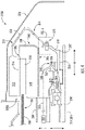
- FIG. 4 provides a close-up, schematic view of the electric machine 300A embedded within the gas turbine engine 210A.
- the electric machine 300A defines a centerline 304, which is aligned with or coaxial with the central longitudinal axis 214 of the gas turbine engine 210A in this example embodiment.
- the electric machine 300A includes a rotor assembly 310 and a stator assembly 340.
- the rotor assembly 310 includes a rotor 312 and the stator assembly 340 includes a stator 342.
- the rotor 312 of the rotor assembly 310 and the stator 342 of the stator assembly 340 together define an air gap 306 therebetween.
- the rotor 312 includes a plurality of magnets 314, such as a plurality of permanent magnets, and the stator 342 includes a plurality of windings or coils 344.
- the electric machine 300A may be referred to as a permanent magnet electric machine.
- the electric machine 300A may be configured in any suitable manner.
- the electric machine 300A may be configured as an electromagnetic electric machine, including a plurality of electromagnets and active circuitry, as an induction type electric machine, a switched reluctance type electric machine, a synchronous AC electric machine, an asynchronous electric machine, or as any other suitable type of electric machine.
- the rotor assembly 310 also includes a rotor connection assembly 316.
- the rotor connection assembly 316 operatively couples the rotor 312 with the low speed shaft 246.
- the rotor connection assembly 316 has a rotor hub 318 and a rotor connection member 320.
- the rotor hub 318 is connected to the low speed shaft 246 and the rotor connection member 320 is connected to the rotor 312.
- the rotor hub 318 and the rotor connection member 320 are mechanically coupled or connected with one another by an insulated joint 322.
- the insulated joint 322 of the rotor connection assembly 316 interrupts common mode electric current from flowing between the rotor 312 and the low speed shaft 246, e.g., from the rotor 312 to the low speed shaft 246. In this way, common mode electric current is prevented from flowing to one or more bearings supporting the low speed shaft 246, among other components.
- the insulated joint 322 will be further described below with reference to FIG. 6 .
- the rotor hub 318 of the rotor connection assembly 316 is connected to the low speed shaft 246 through a splined connection. More particularly, the rotor hub 318 includes a connection portion having a plurality of teeth 324. Similarly, the low speed shaft 246 includes a connection portion having a plurality of teeth 247. The plurality of teeth 324 of the rotor hub 318 are configured to engage with the plurality of teeth 247 of the low speed shaft 246, fixing the two components to one another. In alternative embodiments, the rotor hub 318 may be coupled to the low speed shaft 246 in any other suitable manner.
- the stator assembly 340 also includes a stator connection assembly 346.
- the stator connection assembly 346 includes a stator connection member 348 that supports the stator 342.
- the stator connection member 348 is connected to a structural support member 266 of the turbine section of the gas turbine engine 210A.
- the structural support member 266 can be configured as part of an aft frame assembly of the gas turbine engine 210A.
- the aft frame assembly can include an aft strut 268 ( FIG. 2 ) extending through the turbomachinery flowpath 254 along the radial direction R.
- the aft frame strut 268 provides structural support for the aft end of the cowl 248.
- the gas turbine engine 210A further includes a cavity wall 270 surrounding at least a portion of the electric machine 300A. More specifically, the cavity wall 270 substantially completely surrounds the electric machine 300A, extending from a location proximate a forward end of the electric machine 300A to a location aft of the electric machine 300A along the axial direction A.
- the cavity wall 270 may function as, e.g., a cooling air cavity wall, a sump for cooling fluid, a protective cover for the electric machine 300A, etc.
- the gas turbine engine 210A may further include a second cavity wall (not shown) to form a buffer cavity surrounding the electric machine 300A. The buffer cavity formed by the second cavity wall may thermally protect the electric machine 300A.
- the low speed shaft 246 rotates the rotor assembly 310 of the electric machine 300A, allowing the electric machine 300A to generate electrical power.
- the electric machine 300A is operable in a generator mode.
- the electric machine 300A is operable in a drive mode during certain operations of the gas turbine engine 210A.
- the rotor assembly 310 of the electric machine 300A drives the low speed shaft 246.
- the power converter 188A ( FIG.
- the electric machine 300A can be controlled to provide electrical power to the electric machine 300A via the electric lines 186, e.g., when the electric machine 300A is operating in a drive mode, and electrical power generated by the electric machine 300A can be carried or transmitted to the power converter 188A ( FIG. 2 ) and ultimately to various electrical loads via the electric lines 186, e.g., when the electric machine 300A is operating in a generator mode. As shown best in FIG.
- the electric lines 186 of the power bus 184 may extend through the turbomachinery flowpath 254 (e.g., through the aft frame strut 268) and electrically connect the electric machine 300A to the power converter 188A and ultimately to one or more electrical loads (accessory systems, electric/ hybrid-electric propulsion devices, etc.), electrical sources (other electric machines, electric energy storage units, etc.), or both.
- the electric machine 300A has been described and illustrated in FIG. 4 as having a particular configuration, it will be appreciated that the inventive aspects of the present disclosure may apply to electric machines having alternative configurations.
- the stator assembly 340 and/or rotor assembly 310 may have different configurations or may be arranged in a different manner than illustrated in FIG. 4 .
- the electric machine 300A may have an inner-rotor configuration as shown in FIG. 5 rather than the outer-rotor configuration shown in FIG. 4 .
- the rotor 312 is positioned inward of the stator 342 along the radial direction R.
- an outer-rotor configuration as shown in FIG.
- the rotor 312 is positioned outward of the stator 342 along the radial direction R.
- the electric machine 300A may have a tapered configuration in which the rotor 312 and the stator 342 may extend lengthwise along the axial direction A at an angle with respect to the central longitudinal axis 214, e.g., so that they are not oriented parallel with the central longitudinal axis 214.
- a three-prong solution can be implemented.
- the three-prong solution can include 1) reducing the common mode voltage reaching the electric machine from the power converter connected thereto; 2) interrupting the common mode current conductive path between the rotor of the electric machine and the shaft to which it is coupled; and 3) grounding at least one of the members connecting the rotor of the electric machine and the shaft.
- the common mode voltage reaching the electric machine 300A from its associated power converter 188A can be reduced via an electromagnetic interference filter, or EMI filter.
- the power converter 188A has an electromagnetic interference filter 189A operable to reduce a common mode voltage reaching the electric machine 300A from the power converter 188A.
- the power converter 188A can be electrically coupled with the electric machine 300A by one or more shielded cables.
- the electric line 186 coupling the electric machine 300A with the power converter 188A can include one or more shielded cables.
- the power converter 188A can be electrically coupled with the electric machine 300A by one or more shielded bus bars.
- FIG. 6 provides a close-up, cross-sectional view of the insulated joint 322 taken from Section 5 of FIG. 4 .
- the insulated joint 322 is an insulated bolted joint in this embodiment.
- the insulated joint 322 is collectively formed by a bolt 330, various insulative components, and components of the rotor connection assembly 316.
- the rotor hub 318 includes a hub flange 326 and the rotor connection member 320 includes a connection flange 328.
- the hub flange 326 extends in a plane orthogonal to the axial direction A.
- the connection flange 328 extends in a plane orthogonal to the axial direction A.
- the hub flange 326 and the connection flange 328 are in communication with one another so that bolt 330 may extend through the hub flange 326 and the connection flange 328. More particularly, the hub flange 326 defines an aperture that is in communication with an aperture defined by the connection flange 328.
- the bolt 330 extends through the aperture defined by the hub flange 326 and through the aperture defined by the connection flange 328 to secure the rotor connection member 320 with the rotor hub 318.
- a nut 338 can be threaded onto the bolt 330 to further secure the rotor connection member 320 with the rotor hub 318.
- the bolt 330 has a head 332 and a shank 334 extending from the head 332.
- the head 332 has a larger diameter than the shank 334.
- the head 332 of the bolt 330 is positioned on the hub flange side of the insulated joint 322.
- the shank 334 of the bolt 330 extends through the hub flange 326 and the connection flange 328 and a distal end of the shank 334 is positioned on the connection flange side of the insulated joint 322.
- the nut 338 is secured to the portion of the shank 334 positioned on the connection flange side of the insulated joint 322.
- the head 332 of the bolt 330 and the nut 338 clamp or otherwise couple the rotor hub 318 and the rotor connection member 320 together.
- the bolt 330 and the nut 338 may be formed of an electrically conductive material, such as a suitable metallic material.
- the head 332 of the bolt 330 and the nut 338 may be positioned on opposite sides than what is shown in FIG. 6 .
- the insulated joint 322 includes a plurality of insulative members.
- Each of the insulative members are formed of an electrically insulative material, such as a ceramic material.
- the insulative members electrically isolate the rotor connection member 320 and the rotor hub 318, and thus, the rotor 312 is electrically isolated from the low speed shaft 246.
- the common mode current conductive path between the rotor 312 of the electric machine 300A and the low speed shaft 246 can be interrupted by insulated joint 322.
- the insulative members include a hub shim 333, an interface shim 335, and a connection shim 337.
- each insulative member including the hub shim 333, interface shim 335, and connection shim 337, is formed of an insulative material.
- the hub shim 333 is positioned between the head 332 of the bolt 330 and the hub flange 326, e.g., along the axial direction A.
- the hub shim 333 extends a distance along the radial direction R so that the head 332 of the bolt 330 does not physically contact the hub flange 326 of the rotor hub 318 as shown in FIG. 6 .
- the interface shim 335 is positioned between the rotor hub 318 and the rotor connection member 320 so that they do not physically contact one another. Particularly, as depicted, the interface shim 335 is positioned between the hub flange 326 of the rotor hub 318 and the connection flange 328 of the rotor connection member 320, e.g., along the axial direction A. In addition, for this embodiment, the interface shim 335 is also positioned between an outer member 329 of the hub flange 326 and the rotor connection member 320, e.g., along the radial direction R. In this manner, the interface shim 335 has an L-shaped cross-section in this example embodiment. However, in other example embodiments, the interface shim 335 may have any suitable cross-sectional shape.
- connection shim 337 is positioned between the connection flange 328 and the nut 338, e.g., along the axial direction A.
- the connection shim 337 extends a distance along the radial direction R so that the nut 338 does not physically contact the connection flange 328 of the rotor connection member 320 as shown in FIG. 6 .
- the hub shim 333, the interface shim 335, and the connection shim 337 may each define an aperture.
- the apertures defined by the shims 333, 335, 337 may be in communication with one another as well as the apertures defined by the hub flange 326 and the connection flange 328.
- the bolt 330 may extend through the hub shim 333, the hub flange 326, the interface shim 335, the connection flange 328, and the connection shim 337.
- the bolt 330 may also extend through and may be threadingly engaged with the nut 338.
- the threads or circumference of the shank 334 of the bolt 330 is coated with an insulative coating 339, such as a ceramic coating.
- the insulative coating 339 may extend substantially along the axial length of the shank 334.
- the shank 334 may engage (e.g., threadingly engage) the hub flange 326, the connection flange 328, and the nut 338, all of which may be formed of electrically conductive material.
- the insulative coating 339 on the bolt 330 prevents electric current from flowing between these electrically conductive elements.
- the insulative coating 339 on the bolt 330 and the insulative members, including the hub shim 333, the interface shim 335, and the connection shim 337, collectively electrically isolate the rotor connection member 320 from the rotor hub 318.
- the common mode current conductive path between the rotor 312 of the electric machine 300A and the low speed shaft 246 can be interrupted by insulated joint 322.
- the entire outer surface of the bolt 330 can be coated with the insulative coating 339.
- the bolt 330 is not coated with the insulative coating 339 but rather an insulative sleeve (not shown) may extend circumferentially around and axially along the shank 334 of the bolt 330 so that the bolt 330 does not engage the other electrically conductive components of the insulated joint 322.
- the hub flange 326 and the connection flange 328 can be coated with the insulative coating 339, particularly around the circumference of the apertures 317, 319 through which the bolt 330 extends.
- the hub flange 326 and the connection flange 328 can be coated with the insulative coating 339 in addition or alternatively to the bolt 330 being coated with the insulative coating 339.
- the insulated joint 322 does not include any insulative members but rather the bolt 330, the nut 338, and the flanges 326, 328 are all coated with the insulative coating 339 where they physically engage one another.
- the insulative coating 339 can be applied using a suitable technique, such as by electrophoretic deposition or via an electrostatic coating process. Such techniques can provide an insulation power coating on the desired surfaces ultimately to electrically isolate the rotor connection member 320 and the rotor hub 318 so that the rotor 312 is electrically isolated from the low speed shaft 246. In this way, the common mode current conductive path between the rotor 312 of the electric machine 300A and the low speed shaft 246 can be interrupted by insulated joint 322.
- the rotor hub 318 and/or the rotor connection member 320 can include one or more insulative layers.
- the hub flange 326 includes a plurality of double-layered insulative layers, including hub-side insulative layers, interface-side insulative layers, and aperture insulative layers.
- the bolt 330 and associated nut 338 are removed for illustrative clarity.
- the hub-side insulative layers include an outer layer 400 and an inner layer 402.
- the outer layer 400 forms the outer surface of the hub-side of the hub flange 326.
- a metallic layer 404 is sandwiched or positioned between the outer layer 400 and the inner layer 402, e.g., along the axial direction A.
- the interface-side insulative layers include an outer layer 410 and an inner layer 412.
- the outer layer 410 forms the outer surface of the interface-side of the hub flange 326.
- the outer layer 410 and the inner layer 412 may also extend along the outer member 329 of the hub flange 326.
- a metallic layer 414 is sandwiched or positioned between the outer layer 410 and the inner layer 412, e.g., along the axial direction A and along the radial direction R along the outer member 329 of the hub flange 326.
- the aperture insulative layers include an outer layer 420 and an inner layer 422.
- the aperture insulative layers generally extend circumferentially around the circumference of aperture 317 defined by the hub flange 326 of the rotor hub 318.
- a metallic layer 424 is sandwiched or positioned between the outer layer 420 and the inner layer 422, e.g., along the radial direction R.
- the aperture insulative layers may include only a single layer (e.g., the outer layer 420) extending circumferentially along the circumference defining the aperture 317.
- Each insulative layer of the rotor hub 318 can be formed of an electrically insulative material, such as a ceramic material.
- connection flange 328 includes connection-side insulative layers, interface-side insulative layers, and aperture insulative layers.
- the connection-side insulative layers include an outer layer 430 and an inner layer 432.
- the outer layer 430 forms the outer surface of the connection-side of the connection flange 328.
- a metallic layer 434 is sandwiched or positioned between the outer layer 430 and the inner layer 432, e.g., along the axial direction A.
- the interface-side insulative layers include an outer layer 440 and an inner layer 442.
- the outer layer 440 forms the outer surface of the interface-side of the connection flange 328.
- the outer layer 440 and the inner layer 442 may also extend lengthwise along the axial direction A so as to extend complementary to the interface insulative layers 410, 412 extending along the outer member 329 of the hub flange 326.
- a metallic layer 444 is sandwiched or positioned between the outer layer 440 and the inner layer 442.
- the aperture insulative layers include an outer layer 450 and an inner layer 452.
- the aperture insulative layers generally extend circumferentially around the circumference of aperture 319 defined by the connection flange 328 of the rotor connection member 320.
- a metallic layer 454 is sandwiched or positioned between the outer layer 450 and the inner layer 452, e.g., along the radial direction R.
- the aperture insulative layers may include only a single layer (e.g., the outer layer 450) extending circumferentially along the circumference defining the aperture 319.
- Each insulative layer of the rotor connection member 320 can be formed of an electrically insulative material, such as a ceramic material.
- the strategic arrangement of the insulative layers of the rotor hub 318 and the rotor connection member 320 can electrically isolate the rotor connection member 320 and the rotor hub 318, and thus, the rotor 312 is electrically isolated from the low speed shaft 246.
- the common mode current conductive path between the rotor 312 of the electric machine 300A and the low speed shaft 246 can be interrupted by insulated joint 322.
- the bolt 330 and corresponding nut 338 (not pictured in FIG. 7 ; see FIG. 6 ) can but need not be coated with an insulative material.
- FIG. 6 can but need not be arranged between components as shown in FIG. 6 .
- the double-layered arrangement of the insulative layers depicted in FIG. 7 allows for an outer layer to be easily replaced when worn and also provides an extra layer of insulation, among other benefits.
- the hub flange 326 and the connection flange 328 both include a plurality of single-layered insulative layers.
- the hub flange 326 includes a hub-side insulative layer 460, an interface-side insulative layer 462, and an aperture insulative layer 464.
- the connection flange 328 includes a connection-side insulative layer 466, an interface-side insulative layer 468, and an aperture insulative layer 470.
- Each insulative layer of the rotor hub 318 and the rotor connection member 320 can be formed of an electrically insulative material, such as a ceramic material.
- the bolt 330 and associated nut 338 are removed for illustrative clarity.
- the rotor hub 318 and the rotor connection member 320 can electrically isolate the rotor connection member 320 and the rotor hub 318, and thus, the rotor 312 is electrically isolated from the low speed shaft 246.
- the common mode current conductive path between the rotor 312 of the electric machine 300A and the low speed shaft 246 can be interrupted by insulated joint 322.
- the bolt 330 and corresponding nut 338 (not pictured in FIG. 8 ; see FIG. 6 ) can but need not be coated with an insulative material.
- insulative members such as the insulative shims of FIG. 6 , can but need not be arranged between components as shown in FIG. 6 .
- At least one of the members connecting the rotor 312 of the electric machine 320A and the low speed shaft 246 is electrically grounded by a grounding device 360.
- the grounding device 360 is shown electrically grounding the rotor hub 318, which as noted previously, is a member that connects the rotor 312 of the electric machine 320A and the low speed shaft 246.
- the grounding device 360 can be electrically connected to the rotor hub 318 and a transmission cable 352 can electrically connect the grounding device 360 and a ground point, such as a grounding system 350 (shown schematically in FIG. 4 ).
- the grounding system 350 can be any suitable grounding system, such as an aircraft grounding system. For instance, on an aircraft having a high electrically conductive fuselage, such as an aluminum fuselage, the grounding system 350 can be the fuselage itself.
- an internal metallic structure within the fuselage or other components of the aircraft, such as the wings, tail cone, or empennage of the aircraft, can be used for the grounding system 350.
- the grounding device 360 includes a stationary component 362 connected to a structure of the engine 210A, a rotating component 364 operatively coupled with and rotatable with the rotor hub 318, and one or more electrical contacts 366 connected to one or both of the stationary component 362 and the rotating component 364.
- the electrical contacts 366 can be grounding brushes formed of an electrically conductive material, such as metal or carbon.
- the electrical contacts 366 allow electric current to flow between the stationary component 362 and the rotating component 364 to facilitate grounding of the rotor hub 318.
- the transmission cable 352 is electrically connected to the electrical contacts 366, and thus, the electrical contacts 366 are electrically coupled with the grounding system 350.
- the grounding device 360 can be integrated into an existing component of the gas turbine engine 210A.
- the grounding device 360 is integrated into a resolver operable to measure degrees of rotation or angular position of the rotor hub 318 and the low speed shaft 246 operatively coupled thereto.
- electrical contacts 366 connected to the stationary component 362 can contact the rotating component 364 coupled with the rotor hub 318 to provide an electrical grounding pathway.
- the electrical contacts 366 can be grounding brushes, as noted above. In this regard, a grounding brush can be integrated into the resolver.
- the resolver has dual functionality in that it is operable to provide the grounding connection point for electrically grounding the rotor hub 318 and low speed shaft 246 and it measures degrees of rotation or angular position of the rotor hub 318 and the low speed shaft 246. Integrating the electrical grounding functionality into a resolver can reduce the number of parts required for electrically grounding the rotor hub 318 and low speed shaft 246, can reduce the weight of the first propulsor 200A ( FIG. 1 ) and thus the weight of the aircraft 100 ( FIG. 1 ), and can be an efficient use of space.
- the grounding device 360 can be integrated into other suitable components.
- the grounding device 360 can be integrated into an encoder operable to measure a rotational speed of the rotor hub 318 and the low speed shaft 246 operatively coupled thereto.
- electrical contacts 366 connected to the stationary component 362 of the encoder can contact the rotating component 364 of the encoder coupled with the rotor hub 318 to provide an electrical grounding pathway.
- the electrical contacts 366 can be grounding brushes, as noted above. In this regard, a grounding brush can be integrated into the encoder.
- the encoder has dual functionality in that it is operable to provide the grounding connection point for electrically grounding the rotor hub 318 and low speed shaft 246 and it measures rotational speed of the rotor hub 318 and the low speed shaft 246. Integrating the electrical grounding functionality into an encoder can reduce the number of parts required for electrically grounding the rotor hub 318 and low speed shaft 246, can reduce the weight of the first propulsor 200A ( FIG. 1 ) and thus the weight of the aircraft 100 ( FIG. 1 ), and can be an efficient use of space.
- the shaft electric current and/or shaft voltage can be measured by one or more sensors, represented by sensor 380.
- the sensor 380 can be integrated into the grounding brush circuitry of the grounding device 360, for example.
- the measured shaft electric current and/or shaft voltage can be provided to controller 182 and/or other computing or control devices, e.g., for facilitating control of the electric machine 300A and/or the gas turbine engine 210A.
- the grounding device 360 can be integrated into an existing seal of the gas turbine engine 210A.
- the grounding device 360 can be integrated into any suitable type of existing seal, such as a carbon seal, including end face and radial carbon seals, a finger seal, a brush seal, a labyrinth seal, etc.
- a carbon seal including end face and radial carbon seals, a finger seal, a brush seal, a labyrinth seal, etc.
- the grounding device 360 can be integrated into a carbon seal 370 as depicted in FIG. 9 .
- the carbon seal 370 can be configured to seal a fluid (e.g., oil or air) within a chamber.
- the carbon seal 370 can include a stationary component and a rotating component.
- the stationary component is a stationary carbon element 372 connected to a stationary structure of the engine 210A and the rotating component is a ring 374 rotatable with a rotating shaft, which is the low speed shaft 246 in this example embodiment.
- the ring 374 can be formed of an electrically conductive material, such as a metallic material.
- the state of the carbon element 372 can be such that it is also electrically conductive.
- the grounding element which in this example embodiment is carbon element 372, can be formed of a material other than carbon.
- the grounding element can be formed of any suitable material that is electrically conductive and that has similar wear characteristics to carbon.
- the grounding element can be formed of a suitable composite, mixture, alloy, metal, or other material, for example.
- the carbon element 372 and/or stationary structure to which the carbon element 372 is mounted can be electrically connected to a dedicated grounding system, such as grounding system 350.
- Transmission line 352 can be electrically connected to the carbon element 372 or an adjacent structure electrically coupled with the carbon element 372.
- the grounding system 350 can be used to electrically ground the low speed shaft 246.
- the carbon element 372 and/or its adjacent structures can provide the grounding system.
- the carbon seal 370 has dual functionality in that it is operable to provide the grounding connection point for electrically grounding the low speed shaft 246 and the rotor hub 318 operatively coupled thereto and is operable to seal fluid within a chamber.
- Integrating the electrical grounding functionality into carbon seal 370 can reduce the number of parts required for electrically grounding the rotor hub 318 and low speed shaft 246, can reduce the weight of the first propulsor 200A ( FIG. 1 ) and thus the weight of the aircraft 100 ( FIG. 1 ), and can be an efficient use of space, among other benefits.
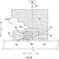
- FIG. 10 provides a close-up, cross-sectional view of another example grounding device 360 integrated into a carbon seal 370 according to one example embodiment of the present disclosure.
- carbon seal 370 is an end face carbon seal.
- the carbon seal 370 includes a plurality of stationary components and a rotating component.
- the stationary components include a first carbon element 480 and a second carbon element 482.
- Both the first carbon element 480 and the second carbon element 482 can be formed of an electrically conductive carbon material.
- the grounding elements which in this example embodiment is first carbon element 480 and second carbon element 482, can be formed of a material other than carbon.
- the grounding elements can be formed of any suitable material that is electrically conductive and that has similar wear characteristics to carbon.
- the grounding elements can be formed of a suitable composite, mixture, alloy, metal, or other material, for example.
- the second carbon element 482 is positioned outward of the first carbon element 480 along the radial direction R.
- the first carbon element 480 and the second carbon element 482 can be carbon rings, for example.
- the first carbon element 480 and the second carbon element 482 can be carried or held in position by a seal holder 484, which is also a stationary component.
- the second carbon element 482 is positioned between two flanges of the seal holder 484 along the radial direction R while the first carbon element 480 is positioned inward of the two flanges of the seal holder 484 along the radial direction R.
- the rotating component is a seal runner 486 that is coupled to and rotatable with the low speed shaft 246.
- the seal runner 486 can be coupled with the rotor hub 318.
- the seal runner 486 can be formed of an electrically conductive material, such as a metallic material.
- a spring 488 is positioned between the seal holder 484 and a seal housing 494, e.g., along the axial direction A. The spring 488 applies a force on the seal holder 484, which biases the first carbon element 480 and the second carbon element 482 in contact with the seal runner 486. As shown in FIG.
- a face 490 of the first carbon element 480 engages the seal runner 486 and a face 492 of the second carbon element 482 engages the seal runner 486.
- the face 492 of the second carbon element 482 engages the seal runner 486 with more surface area than which the face 490 of the first carbon element 480 engages the seal runner 486.
- the seal housing 494 may provide the grounding system in some embodiments, or alternatively, the seal housing 494 may be electrically connected to a dedicated grounding system 350 via transmission line 352. In this manner, the low speed shaft 246, as well as the rotor hub 318 ( FIG. 9 ), can be electrically grounded.
- the carbon seal 370 has dual functionality in that it is operable to provide grounding connection points for electrically grounding the low speed shaft 246 and the rotor hub 318 operatively coupled thereto and is operable to seal fluid within a chamber.
- the engagement of the first carbon element 480 with the seal runner 486 provides sealing functionality along with a first grounding pathway while the engagement of the second carbon element 482 provides a second grounding pathway and increases the number of electrical connection points with the seal runner 486, which may provide improved electrical grounding of the low speed shaft 246. Integrating the electrical grounding functionality into the carbon seal 370 of FIG.
- 10 can reduce the number of parts required for electrically grounding the rotor hub 318 and low speed shaft 246, can reduce the weight of the first propulsor 200A ( FIG. 1 ) and thus the weight of the aircraft 100 ( FIG. 1 ), and can be an efficient use of space, among other benefits.
- FIG. 11 provides a close-up, cross-sectional view of a grounding device 360 integrated into a carbon seal 370 according to another example embodiment of the present disclosure.
- carbon seal 370 is a radial carbon seal.
- the carbon seal 370 includes a carbon element 500 that has a face 502 that directly engages the low speed shaft 246.
- the face 502 can engage the rotor hub 318 of the rotor connection assembly 316 ( FIG. 9 ).
- the carbon element 500 can be formed of an electrically conductive carbon material.
- the carbon element 500 is carried or held by a seal holder 504, which may be mechanically coupled with various support structures.
- a spring 506 is positioned between the seal holder 504 and the carbon element 500. The spring 506 biases the carbon element 500 into the desired axial position.
- the seal holder 504 may provide the grounding system in some embodiments, or alternatively as shown in FIG. 11 , the seal holder 504 may be electrically connected to a dedicated grounding system 350 via transmission line 352. In this manner, the low speed shaft 246, as well as the rotor hub 318 ( FIG. 9 ), can be electrically grounded. Integrating the electrical grounding functionality into the carbon seal 370 of FIG.
- 11 can reduce the number of parts required for electrically grounding the rotor hub 318 and low speed shaft 246, can reduce the weight of the first propulsor 200A ( FIG. 1 ) and thus the weight of the aircraft 100 ( FIG. 1 ), and can be an efficient use of space, among other benefits.
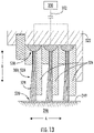
- FIG. 12 provides a close-up, cross-sectional view of a grounding device 360 integrated into a finger seal 510 according to an example embodiment of the present disclosure.
- the finger seal 510 includes a stack or plurality of finger elements 512.
- the plurality of finger elements 512 are positioned between a first plate 514 and a second plate 516, e.g., along the axial direction A.
- the finger elements 512 and the first plate 514 and second plate 516 can be clamped or secured together in any suitable manner, e.g., by one or more mechanical fasteners.
- the plates 514, 516 can be formed of an electrically conductive material, such as a metallic material.
- the finger elements 512 extend along the radial direction R so as to contact the low speed shaft 246. In alternative embodiments, the finger elements 512 can extend to contact other rotating elements coupled with the low speed shaft 246, such as the rotor hub 318 ( FIG. 9 ).
- the finger elements 512 can be formed of a flexible material. In this manner, the finger elements 512 can accommodate displacement and/or deformation of the low speed shaft 246 whilst maintaining contact thereto.
- the flexible material used for the finger elements 512 can also be an electrically conductive material.
- the low speed shaft 246 rotates about the central longitudinal axis 214 ( FIG. 9 )
- an electrical grounding pathway is created between the low speed shaft 246 and the finger elements 512 of the finger seal 510.
- electric current may flow between the low speed shaft 246 and the finger elements 512.
- the plates 514, 516 may provide the grounding system in some embodiments, or alternatively, the plates 514, 516 may be electrically connected to a dedicated grounding system 350 via transmission line 352 as shown in FIG. 12 .
- the low speed shaft 246, as well as the rotor hub 318 ( FIG. 9 ) can be electrically grounded. Integrating the electrical grounding functionality into the finger seal 510 of FIG.
- the 12 can reduce the number of parts required for electrically grounding the rotor hub 318 and low speed shaft 246, can reduce the weight of the first propulsor 200A ( FIG. 1 ) and thus the weight of the aircraft 100 ( FIG. 1 ), and can be an efficient use of space, among other benefits.
- the grounding device 360 can be integrated into a brush seal, such as brush seal 520 depicted in FIG. 13 .
- the brush seal 520 can be configured to seal a fluid (e.g., oil or air) within a chamber.
- the brush seal 520 includes a housing 522 spaced from the low speed shaft 246, e.g., along the radial direction R.
- the brush seal 520 also includes one or more brushes.
- the brush seal 520 includes a plurality of brushes 524.
- Each brush 524 includes a plurality of filaments.
- the filaments can be formed of an electrically conductive material, such as a metallic material.
- Walls 526 can be positioned between adjacent brushes 524, e.g., along the axial direction A. Further, each brush 524 extends between a proximal end 528 and a distal end 530, e.g., along the radial direction R. The brushes 524 are attached to the housing 522 at their respective proximal ends 528. The brushes 524 are engaged with the low speed shaft 246 at their respective distal ends 530.
- the low speed shaft 246 can include a wear resistant coating 249 along its outer circumference as shown in FIG. 13 . The wear resistant coating 249 can prevent damage to the low speed shaft 246 due to engagement of the brushes 524 therewith.
- the brushes 524 can be electrically connected to the grounding system 350 via the transmission line 352.
- the brush seal 520 has dual functionality in that it is operable to provide the grounding connection point for electrically grounding the low speed shaft 246 and the rotor hub 318 operatively coupled thereto and is operable to seal fluid within a chamber.
- Integrating the electrical grounding functionality into brush seal 520 can reduce the number of parts required for electrically grounding the rotor hub 318 and low speed shaft 246, can reduce the weight of the first propulsor 200A ( FIG. 1 ) and thus the weight of the aircraft 100 ( FIG. 1 ), and can be an efficient use of space, among other benefits.
- FIG. 14 provides a flow diagram for a method (600) of operating a hybrid-electric propulsor according to one example embodiment of the present disclosure.
- method (600) can be used to operate one or both of the propulsors 200A, 200B disclosed herein or any other propulsor having a gas turbine engine equipped with an embedded electric machine operatively coupled with a shaft of the engine. It will be appreciated that method (600) is discussed herein to describe exemplary aspects of the present subject matter and is not intended to be limiting.
- the method (600) includes operating a propulsor having a gas turbine engine equipped with an electric machine operatively coupled with a shaft of the gas turbine engine, the electric machine being electrically coupled with a power converter.
- the propulsor can be the first propulsor 200A disclosed herein.
- the electric machine can be embedded within the core of the gas turbine engine can be mechanically coupled with a shaft, such as a low speed shaft, a high-speed shaft, or any other suitable shaft of the gas turbine engine.
- One or more bearings may support the shaft.
- the shaft is rotated about its axis of rotation, and as the rotor of the electric machine is operatively coupled with the shaft, the rotor rotates in unison with the shaft.
- the electric machine may operate in a drive or motor mode.
- the power converter provides electrical power to the electric machine, which causes the electric machine to drive the shaft.
- the electric machine may operate in a generator mode.
- the shaft drives the rotor, causing the electric machine to generate electrical power.
- the generated electrical power can then be provided to the power converter and ultimately to one or more electrical loads.
- common mode voltage can drive common mode electric currents through the electric machine and through electrically conductive components associated with the electric machine.
- the method (600) in operating the propulsor at (602), includes reducing, via an electromagnetic interface filter of the power converter, a common mode voltage reaching the electric machine from the power converter. For instance, an EMI filter of the power converter associated with the propulsor can reduce the common mode voltage reaching the electric machine. In addition, in some implementations, one or more shielded cables or bus bars can further reduce the common mode voltage reaching the electric machine.
- the method (600) includes interrupting, via an insulated joint of a rotor connection assembly operatively coupling a rotor of the electric machine with the shaft, a common mode electric current driven by the power converter to the electric machine from flowing from the rotor to the shaft.
- the insulated joint can be embodied in any of the configurations provided herein.
- the insulated joint can mechanically couple a rotor connection member connected to a rotor of the electric machine and a rotor hub connected to the shaft.
- the insulated joint cannot only mechanically couple the rotor connection member and the rotor hub, but it may also electrically isolate the rotor and the shaft.
- the insulated joint interrupts common mode electric current from flowing from the rotor to the shaft.
- this prevents common mode electric currents from reaching the one or more bearings supporting the shaft.
- the method (600) in operating the propulsor at (602), includes electrically grounding, by a grounding device, the shaft.
- the grounding device can be embodied in any of the configurations provided herein.
- the grounding device can be configured as shown in FIG. 4 .
- the grounding device can have a stationary component, a rotating component connected to the shaft or some other component rotatable with the shaft, and one or more electrical contacts providing an electrical grounding pathway between the rotating component and the stationary component.
- the grounding device is integrated into a resolver operable to measure an angle of the shaft.
- the grounding device is integrated into an encoder operable to measure a rotational speed of the shaft. In some further implementations, the grounding device is integrated into a carbon seal. In some further implementations, the grounding device is integrated into a brush seal.
- the method (600) can include, in combination, reducing the common mode voltage reaching the electric machine at (602A), interrupting common mode electric current from reaching the shaft to which the electric machine is coupled at (602B), and electrically grounding the shaft to which the electric machine is coupled at (602C).
- this may enable achieving a specific fuel burn gain through the circulation of electric power between low speed and high speed spools without shortening the life of the spool bearings.
- this may enable mitigating the spool bearing currents without modification of such bearings and with only minimal modification to the spool rotor structure.
- FIG. 15 provides an example computing system 700 according to example embodiments of the present disclosure.
- the computing systems and devices described herein may include various components and perform various functions of the computing system 700 described below, for example.
- the computing system 700 can include one or more computing device(s) 710.
- the computing device(s) 710 can include one or more processor(s) 710A and one or more memory device(s) 710B.
- the one or more processor(s) 710A can include any suitable processing device, such as a microprocessor, microcontroller, integrated circuit, logic device, and/or other suitable processing device.
- the one or more memory device(s) 710B can include one or more computer-readable media, including, but not limited to, non-transitory computer-readable media, RAM, ROM, hard drives, flash drives, and/or other memory devices.
- the one or more memory device(s) 710B can store information accessible by the one or more processor(s) 710A, including computer-readable instructions 710C that can be executed by the one or more processor(s) 710A.
- the instructions 710C can be any set of instructions that when executed by the one or more processor(s) 710A, cause the one or more processor(s) 710A to perform operations.
- the instructions 710C can be executed by the one or more processor(s) 710A to cause the one or more processor(s) 710A to perform operations, such as any of the operations and functions for which the computing system 700 and/or the computing device(s) 710 are configured.
- the instructions 710C can be software written in any suitable programming language or can be implemented in hardware.
- the instructions 710C can be executed in logically and/or virtually separate threads on processor(s) 710A.
- the memory device(s) 710B can further store data 710D that can be accessed by the processor(s) 710A.
- the data 710D can include models, databases, etc.
- the computing device(s) 710 can also include a network interface 710E used to communicate, for example, with the other components of system 700 (e.g., via a communication network).
- the network interface 710E can include any suitable components for interfacing with one or more network(s), including for example, transmitters, receivers, ports, controllers, antennas, and/or other suitable components.
- One or more devices can be configured to receive one or more commands from the computing device(s) 710 or provide one or more commands to the computing device(s) 710.
Landscapes
- Engineering & Computer Science (AREA)
- Power Engineering (AREA)
- Aviation & Aerospace Engineering (AREA)
- Mechanical Engineering (AREA)
- Chemical & Material Sciences (AREA)
- Combustion & Propulsion (AREA)
- General Engineering & Computer Science (AREA)
- Physics & Mathematics (AREA)
- Electromagnetism (AREA)
- Microelectronics & Electronic Packaging (AREA)
- Connection Of Motors, Electrical Generators, Mechanical Devices, And The Like (AREA)
- Motor Or Generator Frames (AREA)
- Structures Of Non-Positive Displacement Pumps (AREA)
Priority Applications (1)
| Application Number | Priority Date | Filing Date | Title |
|---|---|---|---|
| EP24163075.5A EP4361425A3 (de) | 2021-03-18 | 2022-02-17 | Lagerstromabschwächung für eine in einem gasturbinenmotor eingebettete elektrische maschine |
Applications Claiming Priority (1)
| Application Number | Priority Date | Filing Date | Title |
|---|---|---|---|
| US17/205,028 US11735982B2 (en) | 2021-03-18 | 2021-03-18 | Bearing current mitigation for an electric machine embedded in a gas turbine engine |
Related Child Applications (1)
| Application Number | Title | Priority Date | Filing Date |
|---|---|---|---|
| EP24163075.5A Division EP4361425A3 (de) | 2021-03-18 | 2022-02-17 | Lagerstromabschwächung für eine in einem gasturbinenmotor eingebettete elektrische maschine |
Publications (2)
| Publication Number | Publication Date |
|---|---|
| EP4059846A1 true EP4059846A1 (de) | 2022-09-21 |
| EP4059846B1 EP4059846B1 (de) | 2024-04-17 |
Family
ID=80682448
Family Applications (2)
| Application Number | Title | Priority Date | Filing Date |
|---|---|---|---|
| EP22157192.0A Active EP4059846B1 (de) | 2021-03-18 | 2022-02-17 | Lagerstromabschwächung für eine in einer gasturbine eingebettete elektrische maschine |
| EP24163075.5A Pending EP4361425A3 (de) | 2021-03-18 | 2022-02-17 | Lagerstromabschwächung für eine in einem gasturbinenmotor eingebettete elektrische maschine |
Family Applications After (1)
| Application Number | Title | Priority Date | Filing Date |
|---|---|---|---|
| EP24163075.5A Pending EP4361425A3 (de) | 2021-03-18 | 2022-02-17 | Lagerstromabschwächung für eine in einem gasturbinenmotor eingebettete elektrische maschine |
Country Status (3)
| Country | Link |
|---|---|
| US (3) | US11735982B2 (de) |
| EP (2) | EP4059846B1 (de) |
| CN (2) | CN115149681B (de) |
Families Citing this family (9)
| Publication number | Priority date | Publication date | Assignee | Title |
|---|---|---|---|---|
| US11794915B2 (en) * | 2021-04-27 | 2023-10-24 | Beta Air, Llc | Method and system for a two-motor propulsion system for an electric aircraft |
| US11634232B1 (en) * | 2022-04-30 | 2023-04-25 | Beta Air, Llc | Hybrid propulsion systems for an electric aircraft |
| US12195192B2 (en) * | 2022-04-30 | 2025-01-14 | Beta Air Llc | Hybrid propulsion systems for an electric aircraft |
| US11639230B1 (en) * | 2022-04-30 | 2023-05-02 | Beta Air, Llc | System for an integral hybrid electric aircraft |
| US12583609B2 (en) * | 2022-12-23 | 2026-03-24 | Pratt & Whitney Canada Corp. | Exhaust duct for hybrid aircraft powerplant |
| US12246844B1 (en) * | 2023-11-29 | 2025-03-11 | Pratt & Whitney Canada Corp. | Hybrid aircraft power plant |
| US12595737B2 (en) * | 2023-12-21 | 2026-04-07 | Rtx Corporation | Two piece retractable engine center body for balancing |
| FR3165120A1 (fr) * | 2024-07-29 | 2026-01-30 | AMPERE s.a.s | Machine électrique avec fonction d'évacuation des charges électriques induites dans le rotor. |
| CN120735961B (zh) * | 2025-09-01 | 2025-12-12 | 四川沃飞长空科技发展有限公司 | 电动发动机、电推进装置及飞行器 |
Citations (6)
| Publication number | Priority date | Publication date | Assignee | Title |
|---|---|---|---|---|
| US20160004810A1 (en) * | 2014-07-03 | 2016-01-07 | The Boeing Company | Design of Electromagnetic Interference Filters For Power Converter Applications |
| US20190044405A1 (en) * | 2017-08-07 | 2019-02-07 | General Electric Company | Electrical propulsion system with corona suppression on a vehicle |
| US20200044518A1 (en) * | 2018-08-01 | 2020-02-06 | General Electric Company | Electric Machine Arc Path Protection |
| US20200277994A1 (en) * | 2019-03-01 | 2020-09-03 | Pratt & Whitney Canada Corp. | Turbine engine bearing used as a static electricity leak path |
| US20200385139A1 (en) * | 2019-06-06 | 2020-12-10 | Beta Air, Llc | Integrated electric propulsion assembly |
| EP3763929A1 (de) * | 2019-07-12 | 2021-01-13 | Rolls-Royce plc | Elektrischer generator eines gasturbinentriebwerks |
Family Cites Families (16)
| Publication number | Priority date | Publication date | Assignee | Title |
|---|---|---|---|---|
| US4939506A (en) | 1988-01-26 | 1990-07-03 | Dresser-Rand Company | Grounding brush monitor |
| US5914547A (en) | 1997-11-21 | 1999-06-22 | Magnetek, Inc. | Auxiliary bearing assembly for reduction of unwanted shaft voltages in an electric motor |
| GB9910594D0 (en) * | 1999-05-07 | 1999-07-07 | Rolls Royce Plc | Improved rotor-shaft connector |
| US8189317B2 (en) | 2007-04-23 | 2012-05-29 | Illinois Tool Works Inc. | Grounding brush system for mitigating electrical current on rotating shafts |
| US8277174B2 (en) * | 2007-09-21 | 2012-10-02 | United Technologies Corporation | Gas turbine engine compressor arrangement |
| US20090162139A1 (en) * | 2007-12-19 | 2009-06-25 | General Electric Company | Thermally Insulated Flange Bolts |
| US8376708B2 (en) * | 2009-06-30 | 2013-02-19 | General Electric Company | Drivetrain system for a wind turbine generator and method of assembling the same |
| US8229682B2 (en) | 2009-08-17 | 2012-07-24 | General Electric Company | Apparatus and method for bearing condition monitoring |
| US9097134B2 (en) | 2012-09-14 | 2015-08-04 | Pratt & Whitney Canada Corp. | Air cooling design for tail-cone generator installation |
| PL3465889T3 (pl) | 2016-06-07 | 2021-10-25 | Tesla, Inc. | Zabezpieczenie przed wyładowaniem rotora silnika elektrycznego |
| US10071811B2 (en) * | 2016-08-22 | 2018-09-11 | General Electric Company | Embedded electric machine |
| WO2019051482A1 (en) | 2017-09-11 | 2019-03-14 | Illinois Tool Works Inc. | METHODS AND APPARATUS FOR ATTENUATING ELECTRICAL VOLTAGE ON A ROTATING SHAFT |
| US20190186745A1 (en) * | 2017-12-20 | 2019-06-20 | Plasma Igniter, LLC | Jet engine with plasma-assisted afterburner having Resonator with Fuel Conduit |
| US11156128B2 (en) * | 2018-08-22 | 2021-10-26 | General Electric Company | Embedded electric machine |
| US11333077B2 (en) * | 2019-05-06 | 2022-05-17 | The Boeing Company | Systems and methods for transferring mechanical power in a turbine engine |
| CN111277187B (zh) * | 2020-03-13 | 2023-10-27 | 南京航空航天大学 | 一种航空发动机用永磁发电机径向及扭转力主动控制方法 |
-
2021
- 2021-03-18 US US17/205,028 patent/US11735982B2/en active Active
-
2022
- 2022-02-17 EP EP22157192.0A patent/EP4059846B1/de active Active
- 2022-02-17 EP EP24163075.5A patent/EP4361425A3/de active Pending
- 2022-03-17 CN CN202210267029.0A patent/CN115149681B/zh active Active
- 2022-03-17 CN CN202511480025.0A patent/CN120964051A/zh active Pending
-
2023
- 2023-06-21 US US18/338,390 patent/US12384553B2/en active Active
-
2025
- 2025-07-28 US US19/281,919 patent/US20250353604A1/en active Pending
Patent Citations (6)
| Publication number | Priority date | Publication date | Assignee | Title |
|---|---|---|---|---|
| US20160004810A1 (en) * | 2014-07-03 | 2016-01-07 | The Boeing Company | Design of Electromagnetic Interference Filters For Power Converter Applications |
| US20190044405A1 (en) * | 2017-08-07 | 2019-02-07 | General Electric Company | Electrical propulsion system with corona suppression on a vehicle |
| US20200044518A1 (en) * | 2018-08-01 | 2020-02-06 | General Electric Company | Electric Machine Arc Path Protection |
| US20200277994A1 (en) * | 2019-03-01 | 2020-09-03 | Pratt & Whitney Canada Corp. | Turbine engine bearing used as a static electricity leak path |
| US20200385139A1 (en) * | 2019-06-06 | 2020-12-10 | Beta Air, Llc | Integrated electric propulsion assembly |
| EP3763929A1 (de) * | 2019-07-12 | 2021-01-13 | Rolls-Royce plc | Elektrischer generator eines gasturbinentriebwerks |
Also Published As
| Publication number | Publication date |
|---|---|
| US12384553B2 (en) | 2025-08-12 |
| US20220302801A1 (en) | 2022-09-22 |
| US20230344322A1 (en) | 2023-10-26 |
| US20250353604A1 (en) | 2025-11-20 |
| EP4361425A3 (de) | 2024-06-26 |
| CN115149681A (zh) | 2022-10-04 |
| US11735982B2 (en) | 2023-08-22 |
| EP4361425A2 (de) | 2024-05-01 |
| EP4059846B1 (de) | 2024-04-17 |
| CN115149681B (zh) | 2025-11-07 |
| CN120964051A (zh) | 2025-11-18 |
Similar Documents
| Publication | Publication Date | Title |
|---|---|---|
| US12384553B2 (en) | Bearing current mitigation for an electric machine embedded in a gas turbine engine | |
| US12370908B2 (en) | Propulsion system for an aircraft | |
| EP3421367B1 (de) | Antriebssystem für ein flugzeug | |
| CA3009823C (en) | Propulsion system for an aircraft | |
| US12043399B2 (en) | Hybrid propulsion system for use during uncommanded thrust loss and method of operating | |
| US11008111B2 (en) | Propulsion system for an aircraft | |
| EP3421368B1 (de) | Antriebssystem für ein flugzeug | |
| EP3421369A1 (de) | Antriebssystem für ein flugzeug | |
| US20170253340A1 (en) | Propulsion system for an aircraft | |
| EP3360783A1 (de) | Antriebssystem für ein flugzeug | |
| EP3418197A1 (de) | Antriebssystem für ein flugzeug | |
| US11618580B2 (en) | Hybrid electric aircraft engine | |
| US20180334258A1 (en) | Propulsion system for an aircraft | |
| EP3960633B1 (de) | Grundoperationen eines hybriden elektrischen antriebssystems | |
| EP4529017A1 (de) | Elektrische maschinenanordnung und verfahren zum betrieb davon | |
| US20250242930A1 (en) | Aeronautical power system |
Legal Events
| Date | Code | Title | Description |
|---|---|---|---|
| PUAI | Public reference made under article 153(3) epc to a published international application that has entered the european phase |
Free format text: ORIGINAL CODE: 0009012 |
|
| STAA | Information on the status of an ep patent application or granted ep patent |
Free format text: STATUS: THE APPLICATION HAS BEEN PUBLISHED |
|
| AK | Designated contracting states |
Kind code of ref document: A1 Designated state(s): AL AT BE BG CH CY CZ DE DK EE ES FI FR GB GR HR HU IE IS IT LI LT LU LV MC MK MT NL NO PL PT RO RS SE SI SK SM TR |
|
| STAA | Information on the status of an ep patent application or granted ep patent |
Free format text: STATUS: REQUEST FOR EXAMINATION WAS MADE |
|
| 17P | Request for examination filed |
Effective date: 20230310 |
|
| RBV | Designated contracting states (corrected) |
Designated state(s): AL AT BE BG CH CY CZ DE DK EE ES FI FR GB GR HR HU IE IS IT LI LT LU LV MC MK MT NL NO PL PT RO RS SE SI SK SM TR |
|
| GRAP | Despatch of communication of intention to grant a patent |
Free format text: ORIGINAL CODE: EPIDOSNIGR1 |
|
| STAA | Information on the status of an ep patent application or granted ep patent |
Free format text: STATUS: GRANT OF PATENT IS INTENDED |
|
| RIC1 | Information provided on ipc code assigned before grant |
Ipc: F02K 1/04 20060101ALN20231027BHEP Ipc: B64D 27/02 20060101ALN20231027BHEP Ipc: F02C 7/32 20060101ALI20231027BHEP Ipc: B64D 27/24 20060101ALI20231027BHEP Ipc: B64D 33/00 20060101AFI20231027BHEP |
|
| INTG | Intention to grant announced |
Effective date: 20231120 |
|
| GRAS | Grant fee paid |
Free format text: ORIGINAL CODE: EPIDOSNIGR3 |
|
| GRAA | (expected) grant |
Free format text: ORIGINAL CODE: 0009210 |
|
| STAA | Information on the status of an ep patent application or granted ep patent |
Free format text: STATUS: THE PATENT HAS BEEN GRANTED |
|
| AK | Designated contracting states |
Kind code of ref document: B1 Designated state(s): AL AT BE BG CH CY CZ DE DK EE ES FI FR GB GR HR HU IE IS IT LI LT LU LV MC MK MT NL NO PL PT RO RS SE SI SK SM TR |
|
| REG | Reference to a national code |
Ref country code: GB Ref legal event code: FG4D |
|
| REG | Reference to a national code |
Ref country code: CH Ref legal event code: EP |
|
| P01 | Opt-out of the competence of the unified patent court (upc) registered |
Effective date: 20240326 |
|
| REG | Reference to a national code |
Ref country code: DE Ref legal event code: R096 Ref document number: 602022002852 Country of ref document: DE |
|
| REG | Reference to a national code |
Ref country code: IE Ref legal event code: FG4D |
|
| REG | Reference to a national code |
Ref country code: LT Ref legal event code: MG9D |
|
| REG | Reference to a national code |
Ref country code: NL Ref legal event code: MP Effective date: 20240417 |
|
| REG | Reference to a national code |
Ref country code: AT Ref legal event code: MK05 Ref document number: 1677041 Country of ref document: AT Kind code of ref document: T Effective date: 20240417 |
|
| PG25 | Lapsed in a contracting state [announced via postgrant information from national office to epo] |
Ref country code: NL Free format text: LAPSE BECAUSE OF FAILURE TO SUBMIT A TRANSLATION OF THE DESCRIPTION OR TO PAY THE FEE WITHIN THE PRESCRIBED TIME-LIMIT Effective date: 20240417 |
|
| PG25 | Lapsed in a contracting state [announced via postgrant information from national office to epo] |
Ref country code: NL Free format text: LAPSE BECAUSE OF FAILURE TO SUBMIT A TRANSLATION OF THE DESCRIPTION OR TO PAY THE FEE WITHIN THE PRESCRIBED TIME-LIMIT Effective date: 20240417 |
|
| PG25 | Lapsed in a contracting state [announced via postgrant information from national office to epo] |
Ref country code: IS Free format text: LAPSE BECAUSE OF FAILURE TO SUBMIT A TRANSLATION OF THE DESCRIPTION OR TO PAY THE FEE WITHIN THE PRESCRIBED TIME-LIMIT Effective date: 20240817 |
|
| PG25 | Lapsed in a contracting state [announced via postgrant information from national office to epo] |
Ref country code: BG Free format text: LAPSE BECAUSE OF FAILURE TO SUBMIT A TRANSLATION OF THE DESCRIPTION OR TO PAY THE FEE WITHIN THE PRESCRIBED TIME-LIMIT Effective date: 20240417 |
|
| PG25 | Lapsed in a contracting state [announced via postgrant information from national office to epo] |
Ref country code: HR Free format text: LAPSE BECAUSE OF FAILURE TO SUBMIT A TRANSLATION OF THE DESCRIPTION OR TO PAY THE FEE WITHIN THE PRESCRIBED TIME-LIMIT Effective date: 20240417 Ref country code: FI Free format text: LAPSE BECAUSE OF FAILURE TO SUBMIT A TRANSLATION OF THE DESCRIPTION OR TO PAY THE FEE WITHIN THE PRESCRIBED TIME-LIMIT Effective date: 20240417 |
|
| PG25 | Lapsed in a contracting state [announced via postgrant information from national office to epo] |
Ref country code: GR Free format text: LAPSE BECAUSE OF FAILURE TO SUBMIT A TRANSLATION OF THE DESCRIPTION OR TO PAY THE FEE WITHIN THE PRESCRIBED TIME-LIMIT Effective date: 20240718 |
|
| PG25 | Lapsed in a contracting state [announced via postgrant information from national office to epo] |
Ref country code: PT Free format text: LAPSE BECAUSE OF FAILURE TO SUBMIT A TRANSLATION OF THE DESCRIPTION OR TO PAY THE FEE WITHIN THE PRESCRIBED TIME-LIMIT Effective date: 20240819 |
|
| PG25 | Lapsed in a contracting state [announced via postgrant information from national office to epo] |
Ref country code: ES Free format text: LAPSE BECAUSE OF FAILURE TO SUBMIT A TRANSLATION OF THE DESCRIPTION OR TO PAY THE FEE WITHIN THE PRESCRIBED TIME-LIMIT Effective date: 20240417 |
|
| PG25 | Lapsed in a contracting state [announced via postgrant information from national office to epo] |
Ref country code: AT Free format text: LAPSE BECAUSE OF FAILURE TO SUBMIT A TRANSLATION OF THE DESCRIPTION OR TO PAY THE FEE WITHIN THE PRESCRIBED TIME-LIMIT Effective date: 20240417 |
|
| PG25 | Lapsed in a contracting state [announced via postgrant information from national office to epo] |
Ref country code: PL Free format text: LAPSE BECAUSE OF FAILURE TO SUBMIT A TRANSLATION OF THE DESCRIPTION OR TO PAY THE FEE WITHIN THE PRESCRIBED TIME-LIMIT Effective date: 20240417 |
|
| PG25 | Lapsed in a contracting state [announced via postgrant information from national office to epo] |
Ref country code: LV Free format text: LAPSE BECAUSE OF FAILURE TO SUBMIT A TRANSLATION OF THE DESCRIPTION OR TO PAY THE FEE WITHIN THE PRESCRIBED TIME-LIMIT Effective date: 20240417 |
|
| PG25 | Lapsed in a contracting state [announced via postgrant information from national office to epo] |
Ref country code: PT Free format text: LAPSE BECAUSE OF FAILURE TO SUBMIT A TRANSLATION OF THE DESCRIPTION OR TO PAY THE FEE WITHIN THE PRESCRIBED TIME-LIMIT Effective date: 20240819 Ref country code: PL Free format text: LAPSE BECAUSE OF FAILURE TO SUBMIT A TRANSLATION OF THE DESCRIPTION OR TO PAY THE FEE WITHIN THE PRESCRIBED TIME-LIMIT Effective date: 20240417 Ref country code: NO Free format text: LAPSE BECAUSE OF FAILURE TO SUBMIT A TRANSLATION OF THE DESCRIPTION OR TO PAY THE FEE WITHIN THE PRESCRIBED TIME-LIMIT Effective date: 20240717 Ref country code: LV Free format text: LAPSE BECAUSE OF FAILURE TO SUBMIT A TRANSLATION OF THE DESCRIPTION OR TO PAY THE FEE WITHIN THE PRESCRIBED TIME-LIMIT Effective date: 20240417 Ref country code: IS Free format text: LAPSE BECAUSE OF FAILURE TO SUBMIT A TRANSLATION OF THE DESCRIPTION OR TO PAY THE FEE WITHIN THE PRESCRIBED TIME-LIMIT Effective date: 20240817 Ref country code: HR Free format text: LAPSE BECAUSE OF FAILURE TO SUBMIT A TRANSLATION OF THE DESCRIPTION OR TO PAY THE FEE WITHIN THE PRESCRIBED TIME-LIMIT Effective date: 20240417 Ref country code: GR Free format text: LAPSE BECAUSE OF FAILURE TO SUBMIT A TRANSLATION OF THE DESCRIPTION OR TO PAY THE FEE WITHIN THE PRESCRIBED TIME-LIMIT Effective date: 20240718 Ref country code: FI Free format text: LAPSE BECAUSE OF FAILURE TO SUBMIT A TRANSLATION OF THE DESCRIPTION OR TO PAY THE FEE WITHIN THE PRESCRIBED TIME-LIMIT Effective date: 20240417 Ref country code: ES Free format text: LAPSE BECAUSE OF FAILURE TO SUBMIT A TRANSLATION OF THE DESCRIPTION OR TO PAY THE FEE WITHIN THE PRESCRIBED TIME-LIMIT Effective date: 20240417 Ref country code: BG Free format text: LAPSE BECAUSE OF FAILURE TO SUBMIT A TRANSLATION OF THE DESCRIPTION OR TO PAY THE FEE WITHIN THE PRESCRIBED TIME-LIMIT Effective date: 20240417 Ref country code: AT Free format text: LAPSE BECAUSE OF FAILURE TO SUBMIT A TRANSLATION OF THE DESCRIPTION OR TO PAY THE FEE WITHIN THE PRESCRIBED TIME-LIMIT Effective date: 20240417 Ref country code: RS Free format text: LAPSE BECAUSE OF FAILURE TO SUBMIT A TRANSLATION OF THE DESCRIPTION OR TO PAY THE FEE WITHIN THE PRESCRIBED TIME-LIMIT Effective date: 20240717 |
|
| PG25 | Lapsed in a contracting state [announced via postgrant information from national office to epo] |
Ref country code: DK Free format text: LAPSE BECAUSE OF FAILURE TO SUBMIT A TRANSLATION OF THE DESCRIPTION OR TO PAY THE FEE WITHIN THE PRESCRIBED TIME-LIMIT Effective date: 20240417 |
|
| REG | Reference to a national code |
Ref country code: DE Ref legal event code: R097 Ref document number: 602022002852 Country of ref document: DE |
|
| PG25 | Lapsed in a contracting state [announced via postgrant information from national office to epo] |
Ref country code: EE Free format text: LAPSE BECAUSE OF FAILURE TO SUBMIT A TRANSLATION OF THE DESCRIPTION OR TO PAY THE FEE WITHIN THE PRESCRIBED TIME-LIMIT Effective date: 20240417 |
|
| PG25 | Lapsed in a contracting state [announced via postgrant information from national office to epo] |
Ref country code: CZ Free format text: LAPSE BECAUSE OF FAILURE TO SUBMIT A TRANSLATION OF THE DESCRIPTION OR TO PAY THE FEE WITHIN THE PRESCRIBED TIME-LIMIT Effective date: 20240417 |
|
| PG25 | Lapsed in a contracting state [announced via postgrant information from national office to epo] |
Ref country code: SK Free format text: LAPSE BECAUSE OF FAILURE TO SUBMIT A TRANSLATION OF THE DESCRIPTION OR TO PAY THE FEE WITHIN THE PRESCRIBED TIME-LIMIT Effective date: 20240417 Ref country code: RO Free format text: LAPSE BECAUSE OF FAILURE TO SUBMIT A TRANSLATION OF THE DESCRIPTION OR TO PAY THE FEE WITHIN THE PRESCRIBED TIME-LIMIT Effective date: 20240417 |
|
| PG25 | Lapsed in a contracting state [announced via postgrant information from national office to epo] |
Ref country code: SM Free format text: LAPSE BECAUSE OF FAILURE TO SUBMIT A TRANSLATION OF THE DESCRIPTION OR TO PAY THE FEE WITHIN THE PRESCRIBED TIME-LIMIT Effective date: 20240417 |
|
| PG25 | Lapsed in a contracting state [announced via postgrant information from national office to epo] |
Ref country code: SM Free format text: LAPSE BECAUSE OF FAILURE TO SUBMIT A TRANSLATION OF THE DESCRIPTION OR TO PAY THE FEE WITHIN THE PRESCRIBED TIME-LIMIT Effective date: 20240417 Ref country code: SK Free format text: LAPSE BECAUSE OF FAILURE TO SUBMIT A TRANSLATION OF THE DESCRIPTION OR TO PAY THE FEE WITHIN THE PRESCRIBED TIME-LIMIT Effective date: 20240417 Ref country code: RO Free format text: LAPSE BECAUSE OF FAILURE TO SUBMIT A TRANSLATION OF THE DESCRIPTION OR TO PAY THE FEE WITHIN THE PRESCRIBED TIME-LIMIT Effective date: 20240417 Ref country code: EE Free format text: LAPSE BECAUSE OF FAILURE TO SUBMIT A TRANSLATION OF THE DESCRIPTION OR TO PAY THE FEE WITHIN THE PRESCRIBED TIME-LIMIT Effective date: 20240417 Ref country code: DK Free format text: LAPSE BECAUSE OF FAILURE TO SUBMIT A TRANSLATION OF THE DESCRIPTION OR TO PAY THE FEE WITHIN THE PRESCRIBED TIME-LIMIT Effective date: 20240417 Ref country code: CZ Free format text: LAPSE BECAUSE OF FAILURE TO SUBMIT A TRANSLATION OF THE DESCRIPTION OR TO PAY THE FEE WITHIN THE PRESCRIBED TIME-LIMIT Effective date: 20240417 |
|
| PG25 | Lapsed in a contracting state [announced via postgrant information from national office to epo] |
Ref country code: IT Free format text: LAPSE BECAUSE OF FAILURE TO SUBMIT A TRANSLATION OF THE DESCRIPTION OR TO PAY THE FEE WITHIN THE PRESCRIBED TIME-LIMIT Effective date: 20240417 |
|
| PLBE | No opposition filed within time limit |
Free format text: ORIGINAL CODE: 0009261 |
|
| STAA | Information on the status of an ep patent application or granted ep patent |
Free format text: STATUS: NO OPPOSITION FILED WITHIN TIME LIMIT |
|
| 26N | No opposition filed |
Effective date: 20250120 |
|
| PG25 | Lapsed in a contracting state [announced via postgrant information from national office to epo] |
Ref country code: SI Free format text: LAPSE BECAUSE OF FAILURE TO SUBMIT A TRANSLATION OF THE DESCRIPTION OR TO PAY THE FEE WITHIN THE PRESCRIBED TIME-LIMIT Effective date: 20240417 |
|
| PG25 | Lapsed in a contracting state [announced via postgrant information from national office to epo] |
Ref country code: SE Free format text: LAPSE BECAUSE OF FAILURE TO SUBMIT A TRANSLATION OF THE DESCRIPTION OR TO PAY THE FEE WITHIN THE PRESCRIBED TIME-LIMIT Effective date: 20240417 |
|
| PG25 | Lapsed in a contracting state [announced via postgrant information from national office to epo] |
Ref country code: MC Free format text: LAPSE BECAUSE OF FAILURE TO SUBMIT A TRANSLATION OF THE DESCRIPTION OR TO PAY THE FEE WITHIN THE PRESCRIBED TIME-LIMIT Effective date: 20240417 |
|
| REG | Reference to a national code |
Ref country code: CH Ref legal event code: PL |
|
| PG25 | Lapsed in a contracting state [announced via postgrant information from national office to epo] |
Ref country code: LU Free format text: LAPSE BECAUSE OF NON-PAYMENT OF DUE FEES Effective date: 20250217 |
|
| PG25 | Lapsed in a contracting state [announced via postgrant information from national office to epo] |
Ref country code: CH Free format text: LAPSE BECAUSE OF NON-PAYMENT OF DUE FEES Effective date: 20250228 |
|
| REG | Reference to a national code |
Ref country code: BE Ref legal event code: MM Effective date: 20250228 |
|
| PG25 | Lapsed in a contracting state [announced via postgrant information from national office to epo] |
Ref country code: BE Free format text: LAPSE BECAUSE OF NON-PAYMENT OF DUE FEES Effective date: 20250228 |
|
| PG25 | Lapsed in a contracting state [announced via postgrant information from national office to epo] |
Ref country code: IE Free format text: LAPSE BECAUSE OF NON-PAYMENT OF DUE FEES Effective date: 20250217 |
|
| PGFP | Annual fee paid to national office [announced via postgrant information from national office to epo] |
Ref country code: GB Payment date: 20260121 Year of fee payment: 5 |
|
| PGFP | Annual fee paid to national office [announced via postgrant information from national office to epo] |
Ref country code: DE Payment date: 20260121 Year of fee payment: 5 |
|
| PGFP | Annual fee paid to national office [announced via postgrant information from national office to epo] |
Ref country code: FR Payment date: 20260121 Year of fee payment: 5 |