EP4059849B1 - Procédé d'emballage et unité d'emballage pour articles, en particulier des pailles, avec rejet automatique d'articles défectueux - Google Patents
Procédé d'emballage et unité d'emballage pour articles, en particulier des pailles, avec rejet automatique d'articles défectueux Download PDFInfo
- Publication number
- EP4059849B1 EP4059849B1 EP22163091.6A EP22163091A EP4059849B1 EP 4059849 B1 EP4059849 B1 EP 4059849B1 EP 22163091 A EP22163091 A EP 22163091A EP 4059849 B1 EP4059849 B1 EP 4059849B1
- Authority
- EP
- European Patent Office
- Prior art keywords
- seat
- article
- moving speed
- rejected
- transfer station
- Prior art date
- Legal status (The legal status is an assumption and is not a legal conclusion. Google has not performed a legal analysis and makes no representation as to the accuracy of the status listed.)
- Active
Links
Images


Classifications
-
- B—PERFORMING OPERATIONS; TRANSPORTING
- B65—CONVEYING; PACKING; STORING; HANDLING THIN OR FILAMENTARY MATERIAL
- B65B—MACHINES, APPARATUS OR DEVICES FOR, OR METHODS OF, PACKAGING ARTICLES OR MATERIALS; UNPACKING
- B65B11/00—Wrapping, e.g. partially or wholly enclosing, articles or quantities of material, in strips, sheets or blanks, of flexible material
- B65B11/06—Wrapping articles, or quantities of material, by conveying wrapper and contents in common defined paths
- B65B11/08—Wrapping articles, or quantities of material, by conveying wrapper and contents in common defined paths in a single straight path
- B65B11/10—Wrapping articles, or quantities of material, by conveying wrapper and contents in common defined paths in a single straight path to fold the wrappers in tubular form about contents
-
- B—PERFORMING OPERATIONS; TRANSPORTING
- B65—CONVEYING; PACKING; STORING; HANDLING THIN OR FILAMENTARY MATERIAL
- B65B—MACHINES, APPARATUS OR DEVICES FOR, OR METHODS OF, PACKAGING ARTICLES OR MATERIALS; UNPACKING
- B65B19/00—Packaging rod-shaped or tubular articles susceptible to damage by abrasion or pressure, e.g. cigarettes, cigars, macaroni, spaghetti, drinking straws or welding electrodes
- B65B19/34—Packaging other rod-shaped articles, e.g. sausages, macaroni, spaghetti, drinking straws, welding electrodes
-
- B—PERFORMING OPERATIONS; TRANSPORTING
- B65—CONVEYING; PACKING; STORING; HANDLING THIN OR FILAMENTARY MATERIAL
- B65B—MACHINES, APPARATUS OR DEVICES FOR, OR METHODS OF, PACKAGING ARTICLES OR MATERIALS; UNPACKING
- B65B35/00—Supplying, feeding, arranging or orientating articles to be packaged
- B65B35/10—Feeding, e.g. conveying, single articles
- B65B35/26—Feeding, e.g. conveying, single articles by rotary conveyors
-
- B—PERFORMING OPERATIONS; TRANSPORTING
- B65—CONVEYING; PACKING; STORING; HANDLING THIN OR FILAMENTARY MATERIAL
- B65B—MACHINES, APPARATUS OR DEVICES FOR, OR METHODS OF, PACKAGING ARTICLES OR MATERIALS; UNPACKING
- B65B57/00—Automatic control, checking, warning, or safety devices
- B65B57/10—Automatic control, checking, warning, or safety devices responsive to absence, presence, abnormal feed, or misplacement of articles or materials to be packaged
- B65B57/14—Automatic control, checking, warning, or safety devices responsive to absence, presence, abnormal feed, or misplacement of articles or materials to be packaged and operating to control, or stop, the feed of articles or material to be packaged
-
- B—PERFORMING OPERATIONS; TRANSPORTING
- B65—CONVEYING; PACKING; STORING; HANDLING THIN OR FILAMENTARY MATERIAL
- B65B—MACHINES, APPARATUS OR DEVICES FOR, OR METHODS OF, PACKAGING ARTICLES OR MATERIALS; UNPACKING
- B65B57/00—Automatic control, checking, warning, or safety devices
- B65B57/10—Automatic control, checking, warning, or safety devices responsive to absence, presence, abnormal feed, or misplacement of articles or materials to be packaged
- B65B57/16—Automatic control, checking, warning, or safety devices responsive to absence, presence, abnormal feed, or misplacement of articles or materials to be packaged and operating to stop, or to control the speed of, the machine as a whole
-
- B—PERFORMING OPERATIONS; TRANSPORTING
- B65—CONVEYING; PACKING; STORING; HANDLING THIN OR FILAMENTARY MATERIAL
- B65B—MACHINES, APPARATUS OR DEVICES FOR, OR METHODS OF, PACKAGING ARTICLES OR MATERIALS; UNPACKING
- B65B9/00—Enclosing successive articles, or quantities of material, e.g. liquids or semiliquids, in flat, folded, or tubular webs of flexible sheet material; Subdividing filled flexible tubes to form packages
- B65B9/02—Enclosing successive articles, or quantities of material between opposed webs
- B65B9/04—Enclosing successive articles, or quantities of material between opposed webs one or both webs being formed with pockets for the reception of the articles, or of the quantities of material
- B65B9/045—Enclosing successive articles, or quantities of material between opposed webs one or both webs being formed with pockets for the reception of the articles, or of the quantities of material for single articles, e.g. tablets
-
- B—PERFORMING OPERATIONS; TRANSPORTING
- B65—CONVEYING; PACKING; STORING; HANDLING THIN OR FILAMENTARY MATERIAL
- B65B—MACHINES, APPARATUS OR DEVICES FOR, OR METHODS OF, PACKAGING ARTICLES OR MATERIALS; UNPACKING
- B65B9/00—Enclosing successive articles, or quantities of material, e.g. liquids or semiliquids, in flat, folded, or tubular webs of flexible sheet material; Subdividing filled flexible tubes to form packages
- B65B9/02—Enclosing successive articles, or quantities of material between opposed webs
- B65B9/04—Enclosing successive articles, or quantities of material between opposed webs one or both webs being formed with pockets for the reception of the articles, or of the quantities of material
- B65B2009/047—Rotary pocket formers
Definitions
- the present invention relates to a packing method and to a unit to pack articles, in particular straws.
- the present invention finds advantageous application to the packaging of straws, to which the following disclosure will make explicit reference without thereby losing generality.
- Straws are known which provide a corrugated intermediate portion aimed at allowing the straw to be bent in order to assume, in use, the most adapted shape to satisfy the user.
- a straw is individually packed (namely, it is inserted singularly in its own wrapping) after being bent in a "U" shape (namely, by 180°) in the area of the corrugated intermediate portion (the purpose of the "U” bending is to reduce the overall dimension of the straw); typically, it is required to individually pack the straws bent in a "U” shape when the straws have to be fixed (glued) to the back wall of a beverage container.
- a known packaging machine for individually packing straws comprises: a hopper containing a mass of straws, a withdrawal drum that picks up the straws from the hopper, a bending drum that bends each straw, and a wrapping drum that has a plurality of suction seats each designed to house a portion of a first continuous (namely, seamless) band of wrapping material and a straw.
- Each suction seat of the wrapping drum receives a portion of the first continuous band of wrapping material which is arranged bent in a "U" shape inside the suction seat to define a pocket and then receives a straw (which is placed inside the pocket) directly from the bending drum.
- the wrapping drum is coupled to an applicator drum which applies (typically by heat sealing), to the first continuous band of wrapping material, a second continuous band of wrapping material which closes the pockets containing the straws. Then, a continuous (namely, seamless) succession of pockets each containing a straw is fed, at the output of the wrapping drum; this continuous succession of pockets, each containing a straw, is referred to as a "cartridge belt" in jargon.
- Patent US4384441A1 represents the closest prior art and discloses a machine for the production of a web with individually wrapped drinking straws from two separate plastic films.
- the object of the present invention is to provide a packing method and a unit to pack articles, in particular straws, which are more efficient, avoiding a manual intervention of an operator in case of a defective article or of a missing article.
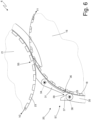
- number 1 denotes as a whole a straw (made of paper or plastic material) which is applied to the back of a beverage package.
- the straw 1 has a flat end 2 (which is grasped by the user's lips) and a pointed end 3 (to more effectively break through the cap that seals a dispensing opening of the package).
- the straw 1 has a corrugated intermediate portion 4 in the area of which the straw 1 can be bent easily and without breaking (namely, in an elastic manner) so as to assume, in use, the most adapted shape in order to satisfy the user.
- the straw 1 is individually packed (namely, it has been inserted singularly in its own wrap 5 not illustrated in Figure 1 and illustrated in Figure 2 ) after being bent in a "U" shape (namely, by 180°) in the area of the corrugated intermediate portion 4 (the purpose of the "U" bending is to reduce the overall dimension of the straw 1 so as to remain within the overall dimensions of the back wall of the package to which the straw 1 is applied).
- number 6 denotes as a whole a packaging machine which receives the straws 1 from a packing machine (not illustrated), corrugates the straws 1, bends the straws 1 in a "U" shape, and inserts the straws 1 in corresponding wraps 5.
- the packaging machine 6 comprises a hopper 7 which is designed to contain a mass of straws 1 coming from the packing machine and which move progressively downwards by gravity, namely, towards the bottom of the hopper 7.
- the packaging machine 6 could provide any buffer or collector of a mass of straws.
- the packaging machine 6 could receive the straws in an orderly manner (that is, not collected in a mass), for example directly from the packing machine.
- a pick-up conveyor 8 is arranged on the bottom of the hopper 7, which, in an input station S1 picks up a succession of straws 1 moving them crosswise (namely, perpendicularly to a longitudinal axis of the straws 1).
- the pick-up conveyor 8 is formed by a drum which is mounted rotatable around a rotation axis 9 (horizontal and perpendicular to the plane of Figure 3 ) and has a plurality of suction seats each designed to house a corresponding straw 1.
- the pick-up conveyor 8 is a conveyor belt, namely, it comprises a flexible belt which is closed in a loop around two end pulleys and supports a plurality of suction seats each designed to house a corresponding straw 1.
- the packaging machine 6 comprises a corrugator drum 10, which is mounted rotatable around a rotation axis 11 (parallel to the rotation axis 9), has a plurality of seats each designed to house a corresponding straw 1, and receives the straws 1 directly from the pick-up conveyor 8 in a transfer station S2.
- a corrugator device 12 is arranged along the periphery of the corrugator drum 10, which corrugates the straws 1, namely, forms the corrugated intermediate portion 4 in each straw 1.
- the packaging machine 6 could receive already corrugated straws 1; in this case, the packaging machine 6 does not comprise the corrugator drum 10.
- the packaging machine 6 comprises a bending drum 13, which is mounted rotatable around a rotation axis 14 (parallel to the rotation axis 11), has a plurality of suction seats each designed to house a corresponding straw 1, and receives the straws 1 directly from the corrugator drum 10 in a transfer station S3.
- Bending elements 15 are arranged around the rotation axis 14 in a fixed position (namely, integral with a frame of the packaging machine 6 and therefore devoid of movement) which are coupled to the bending drum 13 and interact with the straws 1 carried by the suction seats to bend the straws 1 in a "U" shape.
- the packaging machine 6 does not perform the "U" bending of the straws 1; in this case, the packaging machine 6 does not comprise the bending drum 13.
- the packaging machine 6 comprises a reject drum 16, which is mounted rotatable around a rotation axis 17 (parallel to the rotation axis 14), has a plurality of seats 18 (better illustrated in Figures 4-7 ) each designed to house a corresponding straw 1 bent in a "U" shape, receives the straws 1 directly from the bending drum 13 in a transfer station S4, and releases the straws 1 in a transfer station S5 arranged downstream of the transfer station S4 relative to the rotation direction of reject drum 16.
- a reject drum 16 which is mounted rotatable around a rotation axis 17 (parallel to the rotation axis 14), has a plurality of seats 18 (better illustrated in Figures 4-7 ) each designed to house a corresponding straw 1 bent in a "U" shape, receives the straws 1 directly from the bending drum 13 in a transfer station S4, and releases the straws 1 in a transfer station S5 arranged downstream of the transfer station S4 relative to the rotation direction of reject drum 16.
- a control station S6 is arranged between the transfer station S4 and the transfer station S5 and along the periphery of the reject drum 16, which is provided with a control device 19 that is configured to perform a quality control of each straw 1 that is moved from a seat 18 through the control station S6 in order to determine whether the straw 1 complies with the required quality standards and therefore is acceptable or whether the straw 1 does not complies to the required quality standards and therefore it must be rejected.
- the control device 19 comprises at least one video camera which frames a portion of the shell of the reject drum 16 in the area of the control station S6 and performs an optical control of the straws 1 (namely, acquires and analyses at least one digital image of each straw 1).
- a reject station S7 is provided between the control station S6 and the transfer station S5 and along the periphery of the reject drum 16, which is provided with a reject device 20 that is designed to extract a straw 1 from the corresponding seat 18 and therefore direct the extracted straw 1 towards a recovery area (for example, provided with a removable reject container to be periodically emptied).
- the packaging machine 6 comprises a wrapping drum 21, which is mounted rotatable around a rotation axis 22 (parallel to the rotation axis 17), has a plurality of suction seats 23 (better illustrated in the Figures 4-7 ) each designed to house a portion of a continuous (namely, seamless) band 24 of wrapping material and a straw 1 bent in a "U" shape.
- Each suction seat 23 of the wrapping drum 22 receives, in a feeding station S8, a portion of the continuous band 24 of wrapping material which is arranged bent in a "U" shape inside the suction seat 23 to define a pocket and then receives a straw 1 (that is arranged inside the pocket previously formed in the suction seat 23) directly from the reject drum 16 in the transfer station S5.
- An applicator drum 25 is coupled to the wrapping drum 21, which is mounted rotatable around a rotation axis 26 (parallel to the rotation axis 22) and applies (typically by heat sealing) a continuous band 27 of wrapping material, which closes the pockets containing the straws 1, to the continuous band 24 of wrapping material, and in a feeding station S9. Then, a continuous (namely, seamless) succession of pockets, each containing a straw 1, is fed at the output of the wrapping drum 21; this continuous succession of pockets, each containing a straw 1, is referred to as a "cartridge belt" in jargon.
- an inserter drum 28 is provided, which is mounted rotatable around a rotation axis 29 (parallel to the rotation axis 22) and has a plurality of projections, each designed to insert a portion of the continuous band 24 of wrapping material into each seat 23 of the wrapping drum 21, which is arranged, bent in a U-shape, inside the same suction seat 23 thus forming a corresponding pocket.
- the packaging machine 6 comprises an output conveyor 30 which receives the "cartridge belt” (namely, it receives a continuous band 5 of wrapping material containing respective straws 1) from the wrapping drum 21 and moves the "cartridge belt” towards an output of the packaging machine 6.
- the packaging machine 6 comprises a control unit 31 which supervises the operation of all the components of the packaging machine 6.
- the whole packaging machine 6 operates with a law of continuous motion, namely, with movements at a normally constant speed (when the productivity of the packaging machine 6 is stable or in a steady state and therefore not transitory).
- the reject drum 16 moves the seats 18 (each designed to house a straw 1), along a path P1 (that extends from the transfer station S4 to the transfer station S5 and also passes through the control station S6 and the reject station S7) and with a moving speed V1 (schematically illustrated in Figures 5 , 6 and 7 ); furthermore, the wrapping drum 21 moves the seats 23 (each designed to house a straw 1), along a path P2 (that extends from the transfer station S5) and with a moving speed V2 (schematically illustrated in Figures 5 , 6 and 7 ).
- each seat 18 of the reject drum 16 arriving in the transfer station S5 should contain a corresponding transferable straw 1, namely, a straw 1 that can (must) be transferred to a respective seat 23 of the wrapping drum 21 to enter a pocket formed by a portion of a continuous band 24.
- a seat 18 of the reject drum 16 arriving in the transfer station S5 does not contain a transferable straw 1 because the seat 18 is empty (namely, it does not contain any straw 1 at all) or because the seat 18 contains a defective straw 1 (therefore to be rejected and not to be inserted into a seat 23 of the wrapping drum 21 to enter a pocket formed by a portion of a continuous band 24).
- a seat 18 of the reject drum 16 is identified as not containing a transferable straw 1 because it is empty from the beginning of the path P1 or because the straw 1 contained in the seat 18 is identified as defective and therefore to be rejected.
- the control unit 31 optically inspects each seat 18 of the reject drum 16 along the path P1 and in the control station S6 arranged upstream of the transfer station S5 in order to establish whether the seat 18 contains a straw 1 (namely, whether the seat 18 is empty or full) and whether the straw 1 contained in the seat 18 (obviously only if the seat 18 is full) is defective.
- a seat 18 is empty from the beginning of the path P1 due to an undesired and accidental problem (inconvenience, error) that occurred upstream of the path P1 such as, for example, failure to pick up a straw 1 by a suction seat of the pick-up conveyor 8 or loss of a straw 1 from a suction seat of the corrugator drum 10 or from a suction seat of the bending drum 13.
- control unit 31 In case of normal operation during which all the seats 18 contain transferable straws 1 (namely, all the seats 18 are full of respective straws 1 that are not to be rejected), the control unit 31 always maintains the moving speed V1 functionally equal to the moving speed V2 so that, within a same time frame, the same number of seats 18 and 23 pass through the transfer station S5; namely, each seat 18 of the reject drum 16 is "matched up" with one and only one corresponding seat 23 of the wrapping drum 21 so that all the straws 1 that move through the reject drum 16 are transferred to the wrapping drum 21, filling all the seats 23 of the wrapping drum 21.
- control unit 31 does not keep the two moving speeds V1 and V2 equal in absolute terms but keeps them the same in functional terms (namely, by ensuring that the same number of seats 18 and 23 always pass through the exchange station S5 so that each seat 18 can transfer its own straw 1 to a corresponding seat 23 without leaving empty seats 23 downstream of the transfer station S5).
- the absolute value of the moving speeds V1 and V2 depends on the diameter of the drums 16 and 21 and on the number of seats 18 and 23 present in the drums 16 and 21 and the moving speeds V1 and V2 would be not only functionally but also in absolute value the same if the drums 16 and 21 were equal to one another (that is, having the same diameter and having the same number of seats 18 and 23).
- the control unit 31 functionally decreases the moving speed V2 relative to the moving speed V1, so that, within a same exchange time interval, in which one single seat 23 of the wrapping drum 21 passes through the transfer station S5, (at least) two seats 18 of the reject drum 16 (one of which does not contain a transferable straw 1) pass through the transfer station S5; moreover, in these conditions, the control unit 31 makes it possible to transfer, in the transfer station S5 and during the exchange time interval, only the transferable straw 1 (namely, the straw 1 that is different from, other than, any straw 1 to be rejected) from a corresponding seat 18 to a corresponding seat 23.
- the moving speed V2 is decreased to zero, namely, until temporarily stopping the wrapping drum 21.
- the control unit 31 functionally decreases the moving speed V2 relative to the moving speed V1, so that, within a same exchange time interval, in which a single seat 23 of the wrapping drum 21 passes through the transfer station S5, (exactly) two seats 18 of the reject drum 16 (one of which does not contain a transferable straw 1) pass through the transfer station S5; however, it may happen that there is a series of seats 18 of the reject drum 16 not containing a transferable straw 1 and therefore the control unit 31 functionally decreases the moving speed V2 relative to the moving speed V1, so that, within a same exchange time interval, in which a single seat 23 of the wrapping drum 21 passes through the transfer station S5, a series (three, four, five ...) of seats 18 of the reject drum 16 (all except one of them not containing a transferable straw 1) pass through the transfer station S5.
- the reject drum 16 has the effect of interrupting the continuity of the flow of straws 1 avoiding the propagation of voids or straws 1 to be rejected from the section of the machine upstream of the reject drum 16 to the section of the machine downstream of the reject drum 16.
- the reject drum 16 decouples the flow of straws 1 upstream of the reject drum 16 from the flow of straws 1 downstream of the reject drum 16, avoiding the propagation of voids or straws 1 to be rejected and thus ensuring the formation of a complete "cartridge belt" (that is, without voids).
- control unit 31 extracts (if present) any straw 1 to be rejected from the corresponding seat 18 in the reject station S7 (that is arranged upstream of the transfer station S5) so that the seat 18 which initially contained the straw 1 to be rejected arrives empty (and therefore without a transferable straw 1) in the transfer station S5.
- the "hole” created by the absence of the rejected straw 1 in the corresponding seat 18 is "filled” due to the fact that during the exchange time interval (at least) two seats 18 of the reject drum 16 pass (one of which empty, previously containing the straw 1 to be rejected and therefore without a transferable straw 1) through the transfer station S5 and a single seat 23 of the wrapping drum 21; therefore the only seat 23 of the wrapping drum 21 receives a straw 1 and no seat 23 of the wrapping drum 21 remains empty.
- the reject station S7 is provided with a deflector element 32 which is movable between an inactive position (illustrated in Figure 5 ) in which the deflector element 32 does not interfere with the forward movement of the straws 1 housed in the seats 18 of the reject drum 16 and an active position (illustrated in Figure 6 ) in which the deflector element 32 intercepts a straw 1 housed in a seat 18 which moves together with the reject drum 16 by pushing the straw 1 (radially) out of the seat 18.
- the control unit 31 normally holds (namely, when there are no straws 1 to be rejected) the deflector element 32 in the inactive position (illustrated in Figure 5 ); when a straw 1 must be rejected, the control unit 31 moves the deflector element 32 from the inactive position (illustrated in Figure 5 ) to the active position (illustrated in Figure 6 ) immediately upstream of the passage of the seat 18 containing the straw 1 to be rejected and returns the deflector element 32 from the active position (illustrated in Figure 6 ) to the inactive position (illustrated in Figure 5 ) immediately after the passage of the seat 18 containing the straw 1 to be rejected.
- the deflector element 32 has, at the front, an inclined plane 33, which, in the active position (illustrated in Figure 6 ) is oriented crosswise to the path P1 and intercepts the path P1 so that the movement imparted to the straw 1 to be rejected along the path P1 by the conveyor 18 causes the straw 1 to be rejected slide along the inclined plane 33 progressively moving the straw 1 to be rejected away from the path P1 and, hence, from the corresponding seat 18.
- the deflector element 32 is hinged around a rotation axis 34 (parallel to the rotation axis 17) and rotates to move between the inactive position (illustrated in Figure 5 ) and the active position (illustrated in Figure 6 ).
- a side wall 35 is coupled to the reject drum 16 which prevents a straw 1 from getting out of the corresponding seat 18, extends from the transfer station S4 to the transfer station S5 and has a reject opening 36 in the area of the reject station S7; furthermore, a gate 37 is provided, which is movable between a closed position (illustrated in Figure 5 ) in which the gate 37 closes the reject opening 36 and an open position (illustrated in Figure 6 ) in which the gate 37 leaves the reject opening 36 free.
- the control unit 31 moves the gate 37 between the closed position (illustrated in Figure 5 ) and the open position (illustrated in Figure 6 ) simultaneously (namely, in a synchronized manner) with the movement between the inactive position (illustrated in Figure 5 ) and the active position (illustrated in Figure 6 ) of the deflector element 32.
- the gate 37 when the gate 37 is in the open position (illustrated in Figure 6 ) it defines, together with the deflector element 32 which is in the active position (illustrated in Figure 6 ) an output channel 39 through which the straw 1 to be rejected moves away from the corresponding seat 18 of the reject drum 16.
- the gate 37 is hinged around a rotation axis 38 (parallel to the rotation axis 17 and to the rotation axis 34) and rotates to move between the closed position (illustrated in Figure 5 ) and the open position (illustrated in Figure 6 ).
- the nominal speed of the packaging machine 6 is of the order of thousands of straws 6 processed per minute (operating on a single line, namely, of the order of two thousand straws 6 processed per minute operating on a double line) and consequently, the nominal rotation speed of the reject drum 16 (assuming it is provided with thirty-six seats 18) is approximately 0.5 revolutions/second.
- the deflector element 32 may not have sufficient time to move between the inactive position and the active position and vice versa in the time interval that passes between the passage of a seat 18 and of the immediately subsequent seat 18 (since there are structural and functional limits to the accelerations to which the deflector element 32 can be subjected during its movements) through the rejection station S7.
- the control unit 31 can decrease the moving speed V1 of the reject drum 16 down to a predetermined reject value (typically a fraction of the nominal value, for example 5-15% of the nominal value), when the seat 18 containing the straw 1 to be rejected is approaching the reject station S7 so that the seat 18 containing the straw 1 to be rejected passes through the reject station S7 with the moving speed V1 equal to the predetermined reject value.
- a predetermined reject value typically a fraction of the nominal value, for example 5-15% of the nominal value
- the control unit 31 maintains the moving speed V2 of the wrapping drum 21 always functionally equal to the moving speed V1 of the reject drum 16 (excluding the only exception represented by the passage of the seat 18 not containing a transferable straw 1 through the transfer station S5).
- the control unit 31 maintains the moving speed V1 of the reject drum 16 equal to the reject value until the seat 18 containing the straw 1 to be rejected has also passed through the transfer station S5 (namely, not just the reject station S7); in this way also the variation (decrease) of the moving speed V2 of the wrapping drum 21 to the passage of the seat 18 not containing a transferable straw 1 passes through the transfer station S5 occurs when the moving speed V2 of the wrapping drum 21 is (significantly) lower than a nominal value and in this way the decelerations/accelerations to which the wrapping drum 21 is subjected are significantly reduced.
- the control unit 31 reduces the moving speed V2 of the wrapping drum 21 (and therefore also the moving speed V1 of the reject drum 16) to a value (significantly) lower than a nominal value (for example, 5-15% of the nominal value) when the seat 18 not containing a transferable straw 1 passes through the transfer station S5 so as to significantly reduce the decelerations/accelerations to which the wrapping drum 21 is subjected.
- a nominal value for example, 5-15% of the nominal value
- the side wall 35, the periphery of the reject drum 16, the deflector element 21 and the gate 37 are made in a "comb-like" manner so as to be able to mutually interpenetrate without mechanical interference.
- the reject station S7 is arranged upstream of the transfer station S5 relative to the rotation direction of the reject drum 16 and therefore the seat 18 not containing a transferable straw 1 (namely, which initially contained the straw 1 to be rejected) arrives empty in the transfer station S5.
- the reject station S7 is arranged downstream of the transfer station S5 relative to the rotation direction of the reject drum 16 and therefore the seat 18 not containing a transferable straw 1 (namely, still containing the straw 1 to be rejected) arrives (still) full in the transfer station S5 and passes through (namely, still containing the straw 1 to be rejected) the transfer station S5 full.
- the straw 1 to be rejected is extracted from the corresponding seat 18 in the reject station S7 arranged downstream of the transfer station S5 so that the seat 18 not containing a transferable straw 1 (namely, containing the straw 1 to be rejected) passes through the transfer station S5 full.
- the reject station S7 is provided with a deflector element 40, which is permanently arranged in an active position in which the deflector element 40 intercepts a straw 1 housed in a seat 18 that moves together with the reject drum 16 by pushing the straw 1 out of its seat 18.
- the transfer station S5 comprises a pushing element 41, which is movable between an active position (illustrated with a solid line in Figure 7 ) in which the pushing element 41 imparts a thrust to a straw 1 passing through the transfer station S5, which transfers the straw 1 from the corresponding seat 18 to the corresponding seat 23, and an inactive position (illustrated with dashed line in Figure 7 ) in which the pushing element 41 does not interact with a straw 1 passing through the transfer station S5.
- the control unit 31 normally maintains (namely, when there are no straws 1 to be rejected) the pushing element 41 in the active position; when a straw 1 is to be rejected, the control unit 31 moves the pushing element 41 from the active position (illustrated with a solid line in Figure 7 ) to the inactive position (illustrated with dashed line in Figure 7 ) immediately upstream of the passage of the seat 18 not containing a transferable straw 1 (namely, containing the straw 1 to be rejected) and brings the deflector element 32 from the inactive position (illustrated with a dashed line in Figure 7 ) to the active position (illustrated with a solid line in Figure 7 ) immediately after the passage of the seat 18 not containing a transferable straw 1 (namely, containing the straw 1 to be rejected).
- the packaging machine may differ from that illustrated in Figure 3 in that the bending drum 13 coincides with the reject drum 16.
- the machine 1 could comprise: a pick-up conveyor 8 which, in an input station S1, picks up a succession of straws 1 moving them crosswise; a corrugator drum 10, which is mounted rotatable around a rotation axis 11 (parallel to the rotation axis 9), has a plurality of seats each designed to house a corresponding straw 1, and receives the straws 1 directly from the pick-up conveyor 8 in a transfer station S2; a bending (and reject) drum 13, which is mounted rotatable around a rotation axis 14 (parallel to the rotation axis 11), has a plurality of suction seats each designed to house a corresponding straw 1, and receives the straws 1 directly from the corrugator drum 10 in a transfer station S3.
- the moving speed V1 of the reject drum 16 must be (temporarily) varied relative to the moving speed V2 of the wrapping drum 21 when a seat 18 of the reject drum 16 containing a straw 1 to be rejected passes through the transfer station S5. Consequently, and as illustrated in Figure 3 , the reject drum 16 must be rotated by an electric motor 42 (that preferably also rotates the corrugator drum 10 and the bending drum 13), which must be mechanically independent from an electric motor 43 that rotates the wrapping drum 21 (and preferably also rotates the applicator drum 25, the inserter drum 28 and the output conveyor 30). According to a preferred embodiment, a further electric motor 44 is provided, which is mechanically independent from the electric motors 42 and 43 and rotates the pick-up conveyor 8. The three electric motors 42, 43 and 44 have no mechanical constraint between them and are kept synchronized one with the other only by means of the control logic implemented in the control unit 31.
- the packaging machine 6 operates on a double line, namely, it processes two straws 1 arranged side by side (that is, axially aligned with one another) at a time.
- the pick-up conveyor 8 has a series of pairs of suction seats (axially aligned with one another) to pick up two straws 1 at a time from the output mouth of the hopper 7,
- the corrugator drum 10 has a series of pairs of seats (axially aligned with one another), which simultaneously receive two straws 1 from the pick-up conveyor 8, simultaneously corrugate two straws 1 together with the corrugator device 12, and simultaneously release two straws 1 to the bending drum 13.
- the bending drum 13 has a series of pairs of suction seats (axially aligned with one another) which simultaneously receive two straws 1 from the corrugator drum 10, simultaneously bend two straws 1, and simultaneously release two straws 1 to the reject drum 16.
- the reject drum 16 has a series of pairs of seats 18 (axially aligned with one another) which simultaneously receive two straws 1 from the bending drum 13 and simultaneously release two straws 1 to the wrapping drum 21.
- the wrapping drum 21 has a series of pairs of suction seats 23 (axially aligned with one another), which simultaneously receive two straws 1 from the reject drum 16, simultaneously form two wraps 5 (operating with two continuous bands 24 and 27 of wrapping material of double width), and simultaneously release two wraps 5 to the output conveyor 30.
- the output conveyor 30 has a series of pairs of suction seats (axially aligned with one another) which simultaneously receive two wraps 5 from the wrapping drum 21.
- the packaging machine 6 operates on a single line, namely, it processes only one straw 1 at a time.
- the packaging machine 6 operates on a triple or quadruple line, namely, processes three or four straws 1 arranged side by side (that is, axially aligned with one another) at a time.
- the packaging machine 6 described above has numerous advantages. Firstly, the packaging machine 6 described above allows to operate at a high efficiency avoiding manual intervention of an operator in case of a defective straw 1 that must be rejected (namely, extracted from the production flow) or in case of a seat 18 of the reject drum 16 that is empty from the beginning. Furthermore, the packaging machine 6 described above is simple, inexpensive and compact to implement.
Landscapes
- Engineering & Computer Science (AREA)
- Mechanical Engineering (AREA)
- Wrapping Of Specific Fragile Articles (AREA)
- Looms (AREA)
- Making Paper Articles (AREA)
Claims (16)
- Méthode d'emballage pour emballer des articles (1), notamment des pailles, comprenant les étapes de :déplacement, au moyen d'un premier convoyeur (16), de préférence rotatif, de premiers sièges (18), chacun conçu pour loger un article (1), le long d'une première voie (P1) et avec une première vitesse de déplacement (V1) ;déplacement, au moyen d'un deuxième convoyeur (21), de préférence rotatif, de deuxièmes sièges (23), chacun conçu pour loger un article (1), le long d'une deuxième voie (P2) et avec une deuxième vitesse de déplacement (V2) ;amenée, dans une première station d'alimentation (S8) agencée le long de la deuxième voie (P2), dans chaque deuxième siège (23) d'une partie d'une première bande continue (24) de matériau d'emballage qui est agencée dans le deuxième siège (23) de manière à définir une poche ;transfert cyclique d'un article (1) à partir d'un premier siège (18) vers un deuxième siège (23) dans une station de transfert (S5), où les deux voies (P1, P2) se font face et qui est agencée en aval de la première station d'alimentation (S8) afin d'insérer l'article (1) dans une poche correspondante prévue dans le deuxième siège (23) ; etapplication, dans une deuxième station d'alimentation (S9) agencée le long de la deuxième voie (P2) en aval de la station de transfert (S5), sur la première bande continue (24) de matériau d'emballage, d'une deuxième bande continue (27) de matériau d'emballage qui ferme les poches contenant les articles (1) et qui sont agencées dans les deuxièmes sièges (23) ;dans laquelle, en cas de fonctionnement normal pendant lequel tous les premiers sièges (18) contiennent des articles (1) transférables, la première vitesse de déplacement (V1) est fonctionnellement égale à la deuxième vitesse de déplacement (V2), de sorte que, dans un même laps de temps, le même nombre de premiers et deuxièmes sièges (18, 23) se déplacent à travers la station de transfert (S5) ;la méthode d'emballage est caractérisée en ce qu'un premier siège (18) est identifié comme ne contenant pas d'article (1) transférable parce qu'il est vide depuis le début de la première voie (P1) ou parce que l'article (1) contenu dans le premier siège (18) est identifié comme défectueux et donc à rejeter ;et en ce qu'elle comprend, aucas où au moins un premier siège (18) ne contiendrait pas d'article (1) transférable, les étapes supplémentaires de :diminution fonctionnelle de la deuxième vitesse de déplacement (V2) par rapport à la première vitesse de déplacement (V1), de sorte qu'au cours d'un même intervalle de temps d'échange, au cours duquel un seul deuxième siège (23) traverse la station de transfert (S5), au moins deux premiers sièges (18), dont l'un ne contient pas d'article (1) transférable et l'autre contient un article transférable (1), passent par la station de transfert (S5) ; ettransfert, dans la station de transfert (S5) et pendant l'intervalle de temps d'échange, de l'article (1) transférable unique à partir d'un premier siège (18) correspondant vers un deuxième siège (23) correspondant.
- Méthode d'emballage selon la revendication 1 et comprenant l'étape supplémentaire d'inspection optique de chaque premier siège (18) le long de la première voie (P1) et dans une station de contrôle (S6) agencée en amont de la station de transfert (S5) afin d'établir si le premier siège (18) contient un article (1) et si l'article (1) contenu dans le premier siège (18) est défectueux.
- Méthode d'emballage selon la revendication 1 ou 2 et comprenant les étapes supplémentaires de :réduction temporaire, lorsqu'un premier siège (18) ne contenant pas d'article (1) transférable est identifié, à la fois de la première vitesse de déplacement (V1) et de la deuxième vitesse de déplacement (V2) à partir de valeurs normales respectives vers des valeurs de rejet respectives avant de diminuer fonctionnellement la deuxième vitesse de déplacement (V2) par rapport à la première vitesse de déplacement (V1) ; etrétablissement, une fois que le premier siège (18) ne contenant pas d'article (1) transférable a passé la station de transfert (S5), à la fois de la première vitesse de déplacement (V1) et de la deuxième vitesse de déplacement (V2) à partir de leurs valeurs de rejet respectives vers leurs valeurs normales.
- Méthode d'emballage selon la revendication 1, 2 ou 3, dans laquelle la deuxième vitesse de déplacement (V2) est diminuée fonctionnellement par rapport à la première vitesse de déplacement (V1) tout en maintenant constante la première vitesse de déplacement (V1) et en réduisant la deuxième vitesse de déplacement (V2), en particulier en réduisant la deuxième vitesse de déplacement (V2) à zéro, à savoir, jusqu'à l'arrêt temporaire du deuxième convoyeur (21).
- Méthode d'emballage selon l'une quelconque des revendications 1 à 4, dans laquelle les articles (1) sont amenés aux premières poches (18) du premier convoyeur à partir d'un troisième convoyeur (13), le long duquel chaque article (1) est plié en forme de « U ».
- Méthode d'emballage selon l'une quelconque des revendications 1 à 5 et comprenant les étapes supplémentaires de :identification d'un premier siège (18) comme ne contenant pas d'article (1) transférable parce que l'article (1) contenu dans le premier siège (18) est identifié comme défectueux et doit donc être rejeté ; etextraction de l'article (1) à rejeter du premier siège (18) correspondant dans une station de rejet (S7) agencée en amont de la station de transfert (S5) de sorte que le premier siège (18), qui contenait initialement l'article (1) à rejeter, arrive vide à la station de transfert (S5).
- Méthode d'emballage selon la revendication 6, dans laquelle :la station de rejet (S7) est dotée d'un élément déflecteur (32) qui est mobile, notamment articulé, entre une position inactive, dans laquelle l'élément déflecteur (32) n'interfère pas avec le mouvement vers l'avant des articles (1) logés dans les premiers sièges (18) et une position active, dans laquelle l'élément déflecteur (32) intercepte un article (1) logé dans un premier siège (18) qui se déplace avec le premier convoyeur (16), poussant l'article (1) hors du premier siège (18) ;l'élément déflecteur (32) est normalement maintenu dans la position inactive ; etl'élément déflecteur (32) est déplacé à partir de la position inactive vers la position active immédiatement en amont du passage du premier siège (18) contenant l'article (1) à rejeter et est ramené de la position active à la position inactive immédiatement après le passage du premier siège (18) contenant l'article (1) à rejeter.
- Méthode d'emballage selon la revendication 7, dans laquelle la première vitesse de déplacement (V1) est réduite à une valeur de rejet lorsque le premier siège (18) contenant l'article (1) à rejeter s'approche de la station de rejet (S7), de sorte que le premier siège (18) contenant l'article (1) à rejeter passe par la station de rejet (S7) avec la première vitesse de déplacement (V1) égale à la valeur de rejet.
- Méthode d'emballage selon la revendication 8, dans laquelle la première vitesse de déplacement (V1) est maintenue à la valeur de rejet jusqu'à ce que le premier siège (18) contenant l'article (1) à rejeter soit également passé par la station de transfert (S5).
- Méthode d'emballage selon la revendication 7, 8 ou 9, dans laquelle l'élément déflecteur (32) présente, à l'avant, un plan incliné (33) qui, dans la position active, est orienté transversalement par rapport à la première voie (P1) et intercepte la première voie (P1) de sorte que le mouvement imparti à l'article (1) à rejeter le long de la première voie (P1) par le premier convoyeur (18) provoque le glissement de l'article (1) à rejeter le long du plan incliné (33), déplaçant ainsi progressivement l'article (1) à rejeter à l'écart de la première voie (P1) et donc du premier siège (18) correspondant.
- Méthode d'emballage selon l'une quelconque des revendications 7 à 10, dans laquelle :le premier convoyeur (16) est couplé à une paroi latérale (35), qui empêche un article (1) de sortir du siège (18) correspondant et présente une ouverture de rejet (36) dans la zone de la station de rejet (S7) ;une grille (37) est prévue, qui est mobile entre une position fermée, dans laquelle la grille (37) ferme l'ouverture de rejet (36) et une position ouverte, dans laquelle la grille (37) laisse l'ouverture de rejet (36) libre ; etla grille (37) se déplace entre la position fermée et la position ouverte simultanément au mouvement de l'élément déflecteur (32) entre la position inactive et la position active.
- Méthode d'emballage selon la revendication 11, dans laquelle la grille (37), lorsqu'elle est en position ouverte, définit, avec l'élément déflecteur (32) situé dans la position active, un canal de sortie (39) par lequel l'article (1) à rejeter s'éloigne du premier siège (18) correspondant.
- Méthode d'emballage selon l'une quelconque des revendications 1 à 5 et comprenant les étapes supplémentaires de :identification d'un premier siège (18) comme ne contenant pas d'article (1) transférable parce que l'article (1) contenu dans le premier siège (18) est identifié comme défectueux et doit donc être rejeté ; etextraction de l'article (1) à rejeter du premier siège (18) correspondant dans une station de rejet (S7) agencée en aval de la station de transfert (S5), de sorte que le premier siège (18) qui contenait initialement l'article (1) à rejeter soit plein lorsqu'il passe par la station de transfert (S5).
- Méthode d'emballage selon la revendication 13, dans laquelle la station de rejet (S7) est dotée d'un élément déflecteur (41), qui est agencé de manière permanente dans une position active, dans laquelle l'élément déflecteur (41) intercepte un article (1) logé dans un premier siège (18), qui se déplace avec le premier convoyeur (16), poussant l'article (1) hors du premier siège (18).
- Méthode d'emballage selon la revendication 13 ou 14, dans laquelle : la station de transfert (S5) comprend un élément de poussée (42), qui est mobile entre une position active, dans laquelle l'élément de poussée (42) confère une poussée à un article (1) se déplaçant à travers la station de transfert (S5) afin de transférer l'article (1) à partir du premier siège (18) correspondant vers le deuxième siège (23) correspondant, et une position inactive, dans laquelle l'élément de poussée (42) n'interagit pas avec un article (1) se déplaçant à travers la station de transfert (S5) ; etl'élément de poussée (42) est normalement maintenu dans la position active ; etl'élément de poussée (42) est déplacé à partir de la position active vers la position inactive immédiatement en amont du passage du premier siège (18) contenant l'article (1) à rejeter et est ramené à partir de la position inactive vers la position active immédiatement après le passage du premier siège (18) contenant l'article (1) à rejeter.
- Unité d'emballage d'articles (1), notamment de pailles, comprenant :un premier convoyeur (16), de préférence rotatif, qui est configuré pour déplacer des premiers sièges (18), chacun conçu pour loger un article (1), le long d'une première voie (P1) et avec une première vitesse de déplacement (V1) ;un deuxième convoyeur (21), de préférence rotatif, qui est configuré pour déplacer des deuxièmes sièges (23), chacun conçu pour loger un article (1), le long d'une deuxième voie (P2) et avec une deuxième vitesse de déplacement (V2) ;une station d'alimentation (S8) agencée le long de la deuxième voie (P2) et où chaque deuxième siège (23) reçoit une partie d'une bande continue (24) de matériau d'emballage qui est agencée dans le deuxième siège (23) de manière à définir une poche ;une station de transfert (S5) agencée en aval de la première station d'alimentation (S8) et où les deux voies (P1, P2) se font face de manière à transférer cycliquement un article (1) à partir d'un premier siège (18) vers un deuxième siège (23) afin d'insérer l'article (1) dans une poche correspondante prévue dans le deuxième siège (23) ;une deuxième station d'alimentation (S9) agencée le long de la deuxième voie (P2) en aval de la station de transfert (S5) et où une deuxième bande continue (27) de matériau d'emballage est appliquée sur la première bande continue (24) de matériau d'emballage qui ferme les poches contenant les articles (1) et qui sont agencées dans les deuxièmes sièges (23) ; etune unité de commande (31), qui est configurée, en cas de fonctionnement normal pendant lequel tous les premiers sièges (18) contiennent des articles (1) transférables, pour amener la première vitesse de déplacement (V1) à devenir fonctionnellement égale à la deuxième vitesse de déplacement (V2), de sorte que, dans un même laps de temps, le même nombre de premiers et deuxièmes sièges (18, 23) passent par la station de transfert (S5) ;l'unité d'emballage est caractérisée en ce qu'un premier siège (18) est identifié comme ne contenant pas d'article (1) transférable parce qu'il est vide depuis le début de la première voie (P1) ou parce que l'article (1) contenu dans le premier siège (18) est identifié comme défectueux et donc à rejeter ;et en ce que l'unité de commande (31)est configurée, au cas où au moins un premier siège (18) ne contiendrait pas d'article (1) transférable, pour :diminuer fonctionnellement la deuxième vitesse de déplacement (V2) par rapport à la première vitesse de déplacement (V1) de sorte que, dans un même intervalle de temps d'échange, au cours duquel un seul deuxième siège (23) passe par la station de transfert (S5), au moins deux premiers sièges (18), dont l'un ne contient pas d'article (1) transférable et l'autre contient un article (1) transférable, passent par la station de transfert (S5) ; ettransférer, dans la station de transfert (S5) et pendant l'intervalle de temps d'échange, l'article (1) transférable unique à partir d'un premier siège (18) correspondant vers un deuxième siège (23) correspondant.
Applications Claiming Priority (1)
| Application Number | Priority Date | Filing Date | Title |
|---|---|---|---|
| IT102021000006605A IT202100006605A1 (it) | 2021-03-19 | 2021-03-19 | Metodo ed unità di lavorazione di articoli, in particolare cannucce, con scarto automatico degli articoli difettosi |
Publications (2)
| Publication Number | Publication Date |
|---|---|
| EP4059849A1 EP4059849A1 (fr) | 2022-09-21 |
| EP4059849B1 true EP4059849B1 (fr) | 2025-05-07 |
Family
ID=76269848
Family Applications (1)
| Application Number | Title | Priority Date | Filing Date |
|---|---|---|---|
| EP22163091.6A Active EP4059849B1 (fr) | 2021-03-19 | 2022-03-18 | Procédé d'emballage et unité d'emballage pour articles, en particulier des pailles, avec rejet automatique d'articles défectueux |
Country Status (4)
| Country | Link |
|---|---|
| US (1) | US11932434B2 (fr) |
| EP (1) | EP4059849B1 (fr) |
| IT (1) | IT202100006605A1 (fr) |
| PL (1) | PL4059849T3 (fr) |
Families Citing this family (1)
| Publication number | Priority date | Publication date | Assignee | Title |
|---|---|---|---|---|
| JP2024506101A (ja) * | 2021-02-15 | 2024-02-08 | テトラ ラバル ホールディングス アンド ファイナンス エス エイ | 食品パッケージの横方向シールの品質を評価する方法 |
Citations (1)
| Publication number | Priority date | Publication date | Assignee | Title |
|---|---|---|---|---|
| US20180111710A1 (en) * | 2015-05-07 | 2018-04-26 | C.E.R.M.E.X. Constructions Etudes Et Recherches De Materiels Pour L'emballage D'expedition | Controlled feed for batch packaging |
Family Cites Families (6)
| Publication number | Priority date | Publication date | Assignee | Title |
|---|---|---|---|---|
| JPS601206B2 (ja) * | 1979-07-11 | 1985-01-12 | テトラ パツク インタ−ナシヨナル アクチボラグ | フィルムによる棒状物の包装装置 |
| KR960006145Y1 (ko) * | 1992-10-22 | 1996-07-22 | 이상현 | 스트로의 u자 절곡 및 포장장치 |
| IT1274821B (it) * | 1994-07-07 | 1997-07-25 | Gd Spa | Metodo di incarto per la formazione di pacchetti. |
| KR200160426Y1 (ko) * | 1997-06-26 | 1999-11-01 | 김용성 | 젓가락 자동포장기의 불량 감지 및 보충장치 |
| DE102014005959A1 (de) * | 2013-04-30 | 2014-10-30 | Theegarten-Pactec Gmbh & Co. Kg | Verfahren zur Gruppierung von Artikeln zu Artikelstangen und Gruppiereinrichtung sowie Verpackungsmaschine mit einer solchen nebst Steuereinrichtung für Produkt-Halteeinrichtungen |
| DE102018120507A1 (de) * | 2018-08-22 | 2020-02-27 | Singer & Sohn Gmbh | Wurstbehandlungsvorrichtung |
-
2021
- 2021-03-19 IT IT102021000006605A patent/IT202100006605A1/it unknown
-
2022
- 2022-03-18 US US17/698,947 patent/US11932434B2/en active Active
- 2022-03-18 EP EP22163091.6A patent/EP4059849B1/fr active Active
- 2022-03-18 PL PL22163091.6T patent/PL4059849T3/pl unknown
Patent Citations (1)
| Publication number | Priority date | Publication date | Assignee | Title |
|---|---|---|---|---|
| US20180111710A1 (en) * | 2015-05-07 | 2018-04-26 | C.E.R.M.E.X. Constructions Etudes Et Recherches De Materiels Pour L'emballage D'expedition | Controlled feed for batch packaging |
Also Published As
| Publication number | Publication date |
|---|---|
| US20220306327A1 (en) | 2022-09-29 |
| IT202100006605A1 (it) | 2022-09-19 |
| US11932434B2 (en) | 2024-03-19 |
| EP4059849A1 (fr) | 2022-09-21 |
| PL4059849T3 (pl) | 2025-08-04 |
Similar Documents
| Publication | Publication Date | Title |
|---|---|---|
| US4484432A (en) | Bottom-folding packaging machine | |
| US7434374B2 (en) | Method and line for the high-speed packaging of filter bags containing an infusion product | |
| JPH0210007B2 (fr) | ||
| US8938937B2 (en) | Machine and method for packaging fiber material | |
| ITBO980255A1 (it) | Metodo per la realizzazione di pacchetti di sigarette ed impianto per l'attuazione di tale metodo. | |
| CN1466531A (zh) | 包装机的包装材料折入装置 | |
| EP2626305B1 (fr) | Machine à emballer et procédé de production de paquets rigides, comprenant chacun au moins deux récipients, l'un à l'intérieur de l'autre | |
| US6450329B1 (en) | Packet for a group of articles of elongated shape, and a relative method of manufacture | |
| US9309014B2 (en) | Machine with vertical axis for making filter bags with infusion products | |
| EP4059849B1 (fr) | Procédé d'emballage et unité d'emballage pour articles, en particulier des pailles, avec rejet automatique d'articles défectueux | |
| US5564252A (en) | Dual web intermittent motion packaging machine | |
| US20050000188A1 (en) | Product packing machine | |
| CN114379838A (zh) | 一种侧开式烟包的包装工艺 | |
| EP1854724A2 (fr) | Procédé et machine pour produire des paquets de cigarettes | |
| GB2179018A (en) | Sealing wrapped packets | |
| US4584816A (en) | Machine for wrapping and grouping products | |
| GB2138382A (en) | Cigarette packing machines | |
| CN112896593B (zh) | 一种全开式烟包的包装工艺 | |
| GB2150520A (en) | Replacing defective packets between wrapping machine and parceller | |
| EP1394046B1 (fr) | Dispositifs et méthodes pour relier et cercler | |
| EP4458698A1 (fr) | Procédé d'emballage et machine d'emballage pour pailles, avec orientation avant l'emballage | |
| JP3452069B2 (ja) | 鮮度保持剤袋を含んだ包装方法および装置 | |
| CN120462746A (zh) | 一种包装机 | |
| EP2407385B1 (fr) | Unité et procédé pour l'alimentation de feuilles de matériau pour emballer des paquets de cigarettes et machine pour emballer lesdits paquets | |
| CN117508739A (zh) | 一种中支卷烟异型包装工艺及包装设备 |
Legal Events
| Date | Code | Title | Description |
|---|---|---|---|
| PUAI | Public reference made under article 153(3) epc to a published international application that has entered the european phase |
Free format text: ORIGINAL CODE: 0009012 |
|
| STAA | Information on the status of an ep patent application or granted ep patent |
Free format text: STATUS: THE APPLICATION HAS BEEN PUBLISHED |
|
| AK | Designated contracting states |
Kind code of ref document: A1 Designated state(s): AL AT BE BG CH CY CZ DE DK EE ES FI FR GB GR HR HU IE IS IT LI LT LU LV MC MK MT NL NO PL PT RO RS SE SI SK SM TR |
|
| STAA | Information on the status of an ep patent application or granted ep patent |
Free format text: STATUS: REQUEST FOR EXAMINATION WAS MADE |
|
| 17P | Request for examination filed |
Effective date: 20230315 |
|
| RBV | Designated contracting states (corrected) |
Designated state(s): AL AT BE BG CH CY CZ DE DK EE ES FI FR GB GR HR HU IE IS IT LI LT LU LV MC MK MT NL NO PL PT RO RS SE SI SK SM TR |
|
| P01 | Opt-out of the competence of the unified patent court (upc) registered |
Effective date: 20230529 |
|
| GRAP | Despatch of communication of intention to grant a patent |
Free format text: ORIGINAL CODE: EPIDOSNIGR1 |
|
| STAA | Information on the status of an ep patent application or granted ep patent |
Free format text: STATUS: GRANT OF PATENT IS INTENDED |
|
| RIC1 | Information provided on ipc code assigned before grant |
Ipc: B65B 9/04 20060101ALI20241023BHEP Ipc: B65B 57/16 20060101ALI20241023BHEP Ipc: B65B 57/14 20060101ALI20241023BHEP Ipc: B65B 35/26 20060101ALI20241023BHEP Ipc: B65G 47/84 20060101ALI20241023BHEP Ipc: B65B 19/34 20060101AFI20241023BHEP |
|
| INTG | Intention to grant announced |
Effective date: 20241108 |
|
| GRAS | Grant fee paid |
Free format text: ORIGINAL CODE: EPIDOSNIGR3 |
|
| GRAA | (expected) grant |
Free format text: ORIGINAL CODE: 0009210 |
|
| STAA | Information on the status of an ep patent application or granted ep patent |
Free format text: STATUS: THE PATENT HAS BEEN GRANTED |
|
| AK | Designated contracting states |
Kind code of ref document: B1 Designated state(s): AL AT BE BG CH CY CZ DE DK EE ES FI FR GB GR HR HU IE IS IT LI LT LU LV MC MK MT NL NO PL PT RO RS SE SI SK SM TR |
|
| REG | Reference to a national code |
Ref country code: GB Ref legal event code: FG4D |
|
| REG | Reference to a national code |
Ref country code: CH Ref legal event code: EP |
|
| REG | Reference to a national code |
Ref country code: DE Ref legal event code: R096 Ref document number: 602022014095 Country of ref document: DE |
|
| REG | Reference to a national code |
Ref country code: IE Ref legal event code: FG4D |
|
| REG | Reference to a national code |
Ref country code: NL Ref legal event code: FP |
|
| PG25 | Lapsed in a contracting state [announced via postgrant information from national office to epo] |
Ref country code: FI Free format text: LAPSE BECAUSE OF FAILURE TO SUBMIT A TRANSLATION OF THE DESCRIPTION OR TO PAY THE FEE WITHIN THE PRESCRIBED TIME-LIMIT Effective date: 20250507 Ref country code: PT Free format text: LAPSE BECAUSE OF FAILURE TO SUBMIT A TRANSLATION OF THE DESCRIPTION OR TO PAY THE FEE WITHIN THE PRESCRIBED TIME-LIMIT Effective date: 20250908 Ref country code: ES Free format text: LAPSE BECAUSE OF FAILURE TO SUBMIT A TRANSLATION OF THE DESCRIPTION OR TO PAY THE FEE WITHIN THE PRESCRIBED TIME-LIMIT Effective date: 20250507 |
|
| REG | Reference to a national code |
Ref country code: LT Ref legal event code: MG9D |
|
| PG25 | Lapsed in a contracting state [announced via postgrant information from national office to epo] |
Ref country code: GR Free format text: LAPSE BECAUSE OF FAILURE TO SUBMIT A TRANSLATION OF THE DESCRIPTION OR TO PAY THE FEE WITHIN THE PRESCRIBED TIME-LIMIT Effective date: 20250808 Ref country code: NO Free format text: LAPSE BECAUSE OF FAILURE TO SUBMIT A TRANSLATION OF THE DESCRIPTION OR TO PAY THE FEE WITHIN THE PRESCRIBED TIME-LIMIT Effective date: 20250807 |
|
| REG | Reference to a national code |
Ref country code: AT Ref legal event code: MK05 Ref document number: 1792262 Country of ref document: AT Kind code of ref document: T Effective date: 20250507 |
|
| PG25 | Lapsed in a contracting state [announced via postgrant information from national office to epo] |
Ref country code: BG Free format text: LAPSE BECAUSE OF FAILURE TO SUBMIT A TRANSLATION OF THE DESCRIPTION OR TO PAY THE FEE WITHIN THE PRESCRIBED TIME-LIMIT Effective date: 20250507 |
|
| PG25 | Lapsed in a contracting state [announced via postgrant information from national office to epo] |
Ref country code: HR Free format text: LAPSE BECAUSE OF FAILURE TO SUBMIT A TRANSLATION OF THE DESCRIPTION OR TO PAY THE FEE WITHIN THE PRESCRIBED TIME-LIMIT Effective date: 20250507 |
|
| PG25 | Lapsed in a contracting state [announced via postgrant information from national office to epo] |
Ref country code: AT Free format text: LAPSE BECAUSE OF FAILURE TO SUBMIT A TRANSLATION OF THE DESCRIPTION OR TO PAY THE FEE WITHIN THE PRESCRIBED TIME-LIMIT Effective date: 20250507 |
|
| PG25 | Lapsed in a contracting state [announced via postgrant information from national office to epo] |
Ref country code: RS Free format text: LAPSE BECAUSE OF FAILURE TO SUBMIT A TRANSLATION OF THE DESCRIPTION OR TO PAY THE FEE WITHIN THE PRESCRIBED TIME-LIMIT Effective date: 20250807 |
|
| PG25 | Lapsed in a contracting state [announced via postgrant information from national office to epo] |
Ref country code: IS Free format text: LAPSE BECAUSE OF FAILURE TO SUBMIT A TRANSLATION OF THE DESCRIPTION OR TO PAY THE FEE WITHIN THE PRESCRIBED TIME-LIMIT Effective date: 20250907 |
|
| PG25 | Lapsed in a contracting state [announced via postgrant information from national office to epo] |
Ref country code: LV Free format text: LAPSE BECAUSE OF FAILURE TO SUBMIT A TRANSLATION OF THE DESCRIPTION OR TO PAY THE FEE WITHIN THE PRESCRIBED TIME-LIMIT Effective date: 20250507 |
|
| PG25 | Lapsed in a contracting state [announced via postgrant information from national office to epo] |
Ref country code: DK Free format text: LAPSE BECAUSE OF FAILURE TO SUBMIT A TRANSLATION OF THE DESCRIPTION OR TO PAY THE FEE WITHIN THE PRESCRIBED TIME-LIMIT Effective date: 20250507 Ref country code: SM Free format text: LAPSE BECAUSE OF FAILURE TO SUBMIT A TRANSLATION OF THE DESCRIPTION OR TO PAY THE FEE WITHIN THE PRESCRIBED TIME-LIMIT Effective date: 20250507 |
|
| PG25 | Lapsed in a contracting state [announced via postgrant information from national office to epo] |
Ref country code: CZ Free format text: LAPSE BECAUSE OF FAILURE TO SUBMIT A TRANSLATION OF THE DESCRIPTION OR TO PAY THE FEE WITHIN THE PRESCRIBED TIME-LIMIT Effective date: 20250507 |
|
| PG25 | Lapsed in a contracting state [announced via postgrant information from national office to epo] |
Ref country code: EE Free format text: LAPSE BECAUSE OF FAILURE TO SUBMIT A TRANSLATION OF THE DESCRIPTION OR TO PAY THE FEE WITHIN THE PRESCRIBED TIME-LIMIT Effective date: 20250507 |
|
| PG25 | Lapsed in a contracting state [announced via postgrant information from national office to epo] |
Ref country code: SK Free format text: LAPSE BECAUSE OF FAILURE TO SUBMIT A TRANSLATION OF THE DESCRIPTION OR TO PAY THE FEE WITHIN THE PRESCRIBED TIME-LIMIT Effective date: 20250507 |
|
| PG25 | Lapsed in a contracting state [announced via postgrant information from national office to epo] |
Ref country code: IT Free format text: LAPSE BECAUSE OF FAILURE TO SUBMIT A TRANSLATION OF THE DESCRIPTION OR TO PAY THE FEE WITHIN THE PRESCRIBED TIME-LIMIT Effective date: 20250507 |
|
| REG | Reference to a national code |
Ref country code: DE Ref legal event code: R097 Ref document number: 602022014095 Country of ref document: DE |
|
| PLBE | No opposition filed within time limit |
Free format text: ORIGINAL CODE: 0009261 |
|
| STAA | Information on the status of an ep patent application or granted ep patent |
Free format text: STATUS: NO OPPOSITION FILED WITHIN TIME LIMIT |
|
| REG | Reference to a national code |
Ref country code: CH Ref legal event code: L10 Free format text: ST27 STATUS EVENT CODE: U-0-0-L10-L00 (AS PROVIDED BY THE NATIONAL OFFICE) Effective date: 20260318 |
|
| 26N | No opposition filed |
Effective date: 20260210 |