EP4059854A1 - Behälter - Google Patents
Behälter Download PDFInfo
- Publication number
- EP4059854A1 EP4059854A1 EP21162751.8A EP21162751A EP4059854A1 EP 4059854 A1 EP4059854 A1 EP 4059854A1 EP 21162751 A EP21162751 A EP 21162751A EP 4059854 A1 EP4059854 A1 EP 4059854A1
- Authority
- EP
- European Patent Office
- Prior art keywords
- cap
- neck
- circumferential surface
- container
- receptacle
- Prior art date
- Legal status (The legal status is an assumption and is not a legal conclusion. Google has not performed a legal analysis and makes no representation as to the accuracy of the status listed.)
- Withdrawn
Links
- 230000000295 complement effect Effects 0.000 claims abstract description 8
- 238000003780 insertion Methods 0.000 claims abstract description 5
- 230000037431 insertion Effects 0.000 claims abstract description 5
- 239000000463 material Substances 0.000 claims description 6
- 238000007789 sealing Methods 0.000 claims description 6
- 230000003796 beauty Effects 0.000 claims description 5
- 230000001419 dependent effect Effects 0.000 claims description 3
- 239000000853 adhesive Substances 0.000 claims description 2
- 230000001070 adhesive effect Effects 0.000 claims description 2
- 239000004566 building material Substances 0.000 claims description 2
- 238000004140 cleaning Methods 0.000 claims description 2
- 239000002537 cosmetic Substances 0.000 claims description 2
- 229940023487 dental product Drugs 0.000 claims description 2
- 229940127554 medical product Drugs 0.000 claims description 2
- 239000003973 paint Substances 0.000 claims description 2
- 239000000825 pharmaceutical preparation Substances 0.000 claims description 2
- 229940127557 pharmaceutical product Drugs 0.000 claims description 2
- 230000003670 easy-to-clean Effects 0.000 description 1
- 239000007788 liquid Substances 0.000 description 1
- 238000005259 measurement Methods 0.000 description 1
- 238000004806 packaging method and process Methods 0.000 description 1
- 230000002093 peripheral effect Effects 0.000 description 1
- 239000011343 solid material Substances 0.000 description 1
Images




Classifications
-
- B—PERFORMING OPERATIONS; TRANSPORTING
- B65—CONVEYING; PACKING; STORING; HANDLING THIN OR FILAMENTARY MATERIAL
- B65D—CONTAINERS FOR STORAGE OR TRANSPORT OF ARTICLES OR MATERIALS, e.g. BAGS, BARRELS, BOTTLES, BOXES, CANS, CARTONS, CRATES, DRUMS, JARS, TANKS, HOPPERS, FORWARDING CONTAINERS; ACCESSORIES, CLOSURES, OR FITTINGS THEREFOR; PACKAGING ELEMENTS; PACKAGES
- B65D1/00—Rigid or semi-rigid containers having bodies formed in one piece, e.g. by casting metallic material, by moulding plastics, by blowing vitreous material, by throwing ceramic material, by moulding pulped fibrous material or by deep-drawing operations performed on sheet material
- B65D1/02—Bottles or similar containers with necks or like restricted apertures, designed for pouring contents
- B65D1/0223—Bottles or similar containers with necks or like restricted apertures, designed for pouring contents characterised by shape
- B65D1/023—Neck construction
- B65D1/0246—Closure retaining means, e.g. beads, screw-threads
-
- A—HUMAN NECESSITIES
- A45—HAND OR TRAVELLING ARTICLES
- A45D—HAIRDRESSING OR SHAVING EQUIPMENT; EQUIPMENT FOR COSMETICS OR COSMETIC TREATMENTS, e.g. FOR MANICURING OR PEDICURING
- A45D40/00—Casings or accessories specially adapted for storing or handling solid or pasty toiletry or cosmetic substances, e.g. shaving soaps or lipsticks
- A45D40/26—Appliances specially adapted for applying pasty paint, e.g. using roller, using a ball
- A45D40/262—Appliances specially adapted for applying pasty paint, e.g. using roller, using a ball using a brush or the like
- A45D40/265—Appliances specially adapted for applying pasty paint, e.g. using roller, using a ball using a brush or the like connected to the cap of the container
-
- A—HUMAN NECESSITIES
- A45—HAND OR TRAVELLING ARTICLES
- A45D—HAIRDRESSING OR SHAVING EQUIPMENT; EQUIPMENT FOR COSMETICS OR COSMETIC TREATMENTS, e.g. FOR MANICURING OR PEDICURING
- A45D40/00—Casings or accessories specially adapted for storing or handling solid or pasty toiletry or cosmetic substances, e.g. shaving soaps or lipsticks
- A45D40/26—Appliances specially adapted for applying pasty paint, e.g. using roller, using a ball
- A45D40/262—Appliances specially adapted for applying pasty paint, e.g. using roller, using a ball using a brush or the like
- A45D40/265—Appliances specially adapted for applying pasty paint, e.g. using roller, using a ball using a brush or the like connected to the cap of the container
- A45D40/267—Appliances specially adapted for applying pasty paint, e.g. using roller, using a ball using a brush or the like connected to the cap of the container comprising a wiper
-
- B—PERFORMING OPERATIONS; TRANSPORTING
- B65—CONVEYING; PACKING; STORING; HANDLING THIN OR FILAMENTARY MATERIAL
- B65D—CONTAINERS FOR STORAGE OR TRANSPORT OF ARTICLES OR MATERIALS, e.g. BAGS, BARRELS, BOTTLES, BOXES, CANS, CARTONS, CRATES, DRUMS, JARS, TANKS, HOPPERS, FORWARDING CONTAINERS; ACCESSORIES, CLOSURES, OR FITTINGS THEREFOR; PACKAGING ELEMENTS; PACKAGES
- B65D41/00—Caps, e.g. crown caps or crown seals, i.e. members having parts arranged for engagement with the external periphery of a neck or wall defining a pouring opening or discharge aperture; Protective cap-like covers for closure members, e.g. decorative covers of metal foil or paper
- B65D41/02—Caps or cap-like covers without lines of weakness, tearing strips, tags, or like opening or removal devices
- B65D41/04—Threaded or like caps or cap-like covers secured by rotation
- B65D41/0471—Threaded or like caps or cap-like covers secured by rotation with means for positioning the cap on the container, or for limiting the movement of the cap, or for preventing accidental loosening of the cap
-
- B—PERFORMING OPERATIONS; TRANSPORTING
- B65—CONVEYING; PACKING; STORING; HANDLING THIN OR FILAMENTARY MATERIAL
- B65D—CONTAINERS FOR STORAGE OR TRANSPORT OF ARTICLES OR MATERIALS, e.g. BAGS, BARRELS, BOTTLES, BOXES, CANS, CARTONS, CRATES, DRUMS, JARS, TANKS, HOPPERS, FORWARDING CONTAINERS; ACCESSORIES, CLOSURES, OR FITTINGS THEREFOR; PACKAGING ELEMENTS; PACKAGES
- B65D51/00—Closures not otherwise provided for
- B65D51/24—Closures not otherwise provided for combined or co-operating with auxiliary devices for non-closing purposes
- B65D51/32—Closures not otherwise provided for combined or co-operating with auxiliary devices for non-closing purposes with brushes or rods for applying or stirring contents
-
- B—PERFORMING OPERATIONS; TRANSPORTING
- B65—CONVEYING; PACKING; STORING; HANDLING THIN OR FILAMENTARY MATERIAL
- B65D—CONTAINERS FOR STORAGE OR TRANSPORT OF ARTICLES OR MATERIALS, e.g. BAGS, BARRELS, BOTTLES, BOXES, CANS, CARTONS, CRATES, DRUMS, JARS, TANKS, HOPPERS, FORWARDING CONTAINERS; ACCESSORIES, CLOSURES, OR FITTINGS THEREFOR; PACKAGING ELEMENTS; PACKAGES
- B65D53/00—Sealing or packing elements; Sealings formed by liquid or plastics material
- B65D53/02—Collars or rings
-
- B—PERFORMING OPERATIONS; TRANSPORTING
- B65—CONVEYING; PACKING; STORING; HANDLING THIN OR FILAMENTARY MATERIAL
- B65D—CONTAINERS FOR STORAGE OR TRANSPORT OF ARTICLES OR MATERIALS, e.g. BAGS, BARRELS, BOTTLES, BOXES, CANS, CARTONS, CRATES, DRUMS, JARS, TANKS, HOPPERS, FORWARDING CONTAINERS; ACCESSORIES, CLOSURES, OR FITTINGS THEREFOR; PACKAGING ELEMENTS; PACKAGES
- B65D2251/00—Details relating to container closures
- B65D2251/07—Closures specially adapted for closing bottle-necks of non-circular cross-section
-
- B—PERFORMING OPERATIONS; TRANSPORTING
- B65—CONVEYING; PACKING; STORING; HANDLING THIN OR FILAMENTARY MATERIAL
- B65D—CONTAINERS FOR STORAGE OR TRANSPORT OF ARTICLES OR MATERIALS, e.g. BAGS, BARRELS, BOTTLES, BOXES, CANS, CARTONS, CRATES, DRUMS, JARS, TANKS, HOPPERS, FORWARDING CONTAINERS; ACCESSORIES, CLOSURES, OR FITTINGS THEREFOR; PACKAGING ELEMENTS; PACKAGES
- B65D2501/00—Containers having bodies formed in one piece
- B65D2501/0009—Bottles or similar containers with necks or like restricted apertures designed for pouring contents
- B65D2501/009—Necks of non-circular cross-section
Definitions
- the invention concerns a receptacle comprising a container and a cap, the cap being repeatedly attachable to the container for closure of the receptacle.
- Receptacles of this kind are used for many applications including the packaging of beauty products such as mascara.
- multiple systems are known, e.g. profiled threads, a bayonet lock, a swiveling cap in combination with snap on, a wire hanger as clip lock, an eccentric handle to compress a sealing, or a bistable snap cover.
- a receptacle comprising a container and a cap, the cap being repeatedly attachable to the container for closure of the receptacle, the cap having a passage having an opening formed therein, the container having a neck for insertion into the passage via the opening of the cap along a longitudinal axis of the receptacle, wherein the opening of the cap has a non-circular shaped inner contour formed complementary to a non-circular shaped outer contour of the neck, wherein an inner circumferential surface of the passage and an outer circumferential surface of the neck are formed so that a form-fitting engagement in the axial direction is generable by rotating the cap relative to the container around the longitudinal axis, and wherein the inner circumferential surface of the passage and the outer circumferential surface of the neck are formed so that a press-fitting engagement in a radial direction between the inner circumferential surface of the passage and the outer circumferential surface of the neck is generable
- the invention is based on the idea that the cap and the container are attached to each other by first generating a form-fitting engagement - e.g. similar to a thread - in the axial direction and then generating a press-fitting engagement which - different to a thread - is generated in a radial direction between the inner circumferential surface of the passage and the outer circumferential surface of the neck by rotating a non-circular section of the passage in the cap relative to a non-circular section of the neck of the container.
- Embodiments of the receptacle are defined by the dependent claims and described in the following disclosure.
- the non-circular shaped inner contour of the cap can extend along a subsection of the passage or along substantially the whole passage. Accordingly, the non-circular shaped outer contour of the neck can extend along a subsection of the neck or along substantially the whole neck.
- the outer circumferential surface of the neck is formed as an outer circumferential surface of a twisted non-circular element; and the inner circumferential surface of the passage is correspondingly formed as an inner circumferential surface of a twisted non-circular pipe, in particular a twisted non-cylindrically shaped pipe that is twisted so that sections of this pipe in a plane perpendicular to the longitudinal axis are non-circular, so that the cap can be attached onto the neck of the container.
- the neck has non-circular shaped cross-sections with constant sizes along the longitudinal axis, but the orientation of the non-circular cross-sections changes constantly so that points of the surface that are equally distanced from the longitudinal axis of the neck are arranged along a helix.
- a receptacle comprising a container and a cap
- the cap being repeatedly attachable to the container for closure of the receptacle, the cap having a passage having an opening formed therein, the container having a neck for insertion into the passage via the opening of the cap along a longitudinal axis of the receptacle, wherein the opening of the cap has a non-circular shaped inner contour formed complementary to a non-circular shaped outer contour of the neck, wherein an outer circumferential surface of the neck is formed as an outer circumferential surface of a twisted non-circular element; and an inner circumferential surface of the passage is correspondingly formed as an inner circumferential surface of a twisted non-circular pipe so that the cap can be attached onto the neck of the container by rotating the cap relative to the container.
- the non-circular contour of the neck and/or the passage has a symmetrical circumferential shape.
- the circumferential shape can be mirror-symmetrical, e.g. can have an oval shape. This allows to attach the cap onto the neck starting in two different angular positions.
- the circumferential shape can be rotationally symmetrical, e.g. can be shaped like a hyperbolic polygon, e.g. trigon. This simplifies attaching the cap to the neck because it allows placing the cap onto the neck in, e.g. three, different angular positions.
- the inner circumferential surface of the passage and the outer circumferential surface of the neck are formed and/or configured so that by rotating the cap relative to the container around the longitudinal axis, the cap is forced towards the container along the longitudinal axis. This allows that the cap can be attached onto the neck of the container easily.
- the inner circumferential surface of the passage can have multiple concave surfaces and the outer circumferential surface of the neck can have corresponding convex circumferential surfaces that allow jamming the cap onto the neck by rotating the cap relative to the neck of the container. In particular, this should be only possible in regular operation when the cap is fully attached onto the neck of the container.
- the outer circumferential surface of the neck can be formed as an outer circumferential surface of a non-circular element twisted by 360° or less and the inner circumferential surface of the passage can be correspondingly formed as an inner circumferential surface of a non-circular pipe twisted by 360° or less.
- the outer circumferential surface of the neck can be formed as an outer circumferential surface of a non-circular element twisted about 180° and the inner circumferential surface of the passage can be correspondingly formed as an inner circumferential surface of a non-circular pipe twisted about 180°.
- the press-fitting engagement can be generable by proceeding to rotate the cap relative to the neck by 5° to 20° after being fully attached onto the neck.
- the contour of the neck along the longitudinal axis and/or the circumferential direction can be continuous.
- an even smoother surface can be achieved if a pitch of the contour of the neck along the longitudinal axis and/or the circumferential direction is continuous.
- the contour of the neck along the longitudinal axis and/or the circumferential direction can be continuous in curvature and gradient. This creates a smooth and easy to clean surface.
- the neck can have a continuous outer peripheral extent in a majority of sectional planes perpendicular to the longitudinal axis, in particular in all of its sectional planes. Furthermore, the outer circumference of the neck in these sectional planes can be formed by non-concentric sections.
- the contour of the passage along the longitudinal axis and/or the circumferential direction can be continuous. Furthermore, for the reasons mentioned above, a pitch of the contour of the passage along the longitudinal axis and/or the circumferential direction can be continuous. In particular, the contour of the passage along the longitudinal axis and/or the circumferential direction can be continuous in curvature and gradient.
- the inner contour of the passage can be continuous in a majority of sectional planes perpendicular to the longitudinal axis, in particular in all of its sectional planes perpendicular to the longitudinal axis.
- the inner contour of the passage in these sectional planes can be formed by non-concentric sections.
- the non-circular shaped inner contour of the opening of the cap and/or the non-circular shaped outer contour of the neck is selected from the group of shape members consisting of an oval shape, an elliptical shape, a hyperbolic shape, and a hyperbolic trigon, i.e. a triangle with rounded edges.
- the non-circular contour preferably is symmetrical and/or does not form any sharp edges.
- a ratio of the width to height of the non-circular shaped inner contour of the opening in a plane transverse to the longitudinal axis of the receptacle is selected in the range of: 80-95% dependent on the diameter of the receptacle.
- a smallest diameter of the contour is between 0.8 to 0.95 times as long as a longest diameter of the contour.
- the inner contour of the cap and the outer contour of the neck form a clearance fit when the cap attached onto the neck.
- the inner contour of the cap is 0.5 % to 2.0 % larger than the outer contour of the neck.
- each inner diameter of the passage is 0.5 % to 2.0 % larger than the respective outer diameter of the neck.
- one or more seals are arranged between the neck and the cap for sealing between the neck and the cap when the cap is installed at the container.
- the seal is preferably arranged between an inner surface of the neck and the cap, in particular an inner support structure of the cap.
- an applicator can be arranged at the cap.
- the seal can be arranged between an inner surface of the neck and a support structure for the applicator.
- the receptacle further comprises a securing device, the securing device configured to provide at least one of an audible click and a tangible resistance when the cap is completely installed at the neck.
- This securing device can comprise an undulating surface, in particular a plurality of peaks separated by a plurality of valleys.
- the securing device can comprise one or more domes.
- the securing device can be formed on the inner circumferential surface of the passage and the outer circumferential surface of the neck. The securing device may break through the general continuity of the inner and outer circumferential surfaces as long as they do not disturb the attachability of the cap onto the neck.
- the container can have a material stored therein, with said material being a liquid, a paste, or a pourable solid material.
- said material can be selected from the group of members consisting of: a beauty product, a cosmetic product, a cleaning product, a skin care product, a medical product, a dental product, a pharmaceutical product, an adhesive, a paint, and a building material.
- the container is configured to hold at least one of said materials.
- Fig. 1 depicts a receptacle 10 with a container 12 and a cap 14.
- the cap 14 is repeatedly attachable to the container 12 in order to close the receptacle 10.
- the cap 14 has a passage 16 extending in a longitudinal axis A of the receptacle 10 with an opening 16a in one of its end regions.
- the cap 14 has a blind hole formed therein.
- the container 12 has a neck 18 that is configured to be inserted into the passage 16 via the opening 16a.
- the passage 16 has an inner circumferential shape along the longitudinal axis, i.e. an inner contour 20, that is non-circular shaped at least over a majority of the length of the passage 16, with the majority of the length being at least 51 % preferably at least 80 % of the length of the passage 16.
- the non-circular shaped inner contour 20 varies along the longitudinal axis so that points on the contour being equidistant to the longitudinal axis form a helix 21.
- the passage 16 has an inner circumferential surface that is formed as an inner circumferential surface of a twisted non-circular pipe.
- the neck 18 has an outer circumferential shape along the longitudinal axis, i.e. an outer contour 22, that is non-circular shaped.
- the outer contour 22 is shaped complementary to the inner contour 20, to enable the cap 14 to be attached to the neck 18 by rotating the cap 14 relative to the container 12.
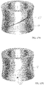
- the non-circular shaped outer contour 22 varies along the longitudinal axis so that points on the contour being equidistant to the longitudinal axis A form a helix 23 (see Fig. 5B ) having the same pitch or gradient as the helix 21 formed by the inner contour 20.
- the neck 18 has an outer circumferential surface that is formed as an outer circumferential surface of a twisted non-circular element.
- the outer contour 22 of the neck 18 has a convex outer surface 22a and the inner contour 20 of the cap 14 in a fully attached state forms a corresponding concave surface 20a.
- the outer contour 22 of the neck 18 in a second sectional view, has a concave outer surface 22b and the inner contour 20 of the cap 14 in a fully attached state forms a corresponding convex surface 20b.
- the outer contour 22 of the neck 18 comprises a surface which includes both the convex outer surface 22a and the concave outer surface 22b, with a relative position of the different shapes of the outer contour 22 varying both radially and axially relative to the longitudinal axis A to form an engagement surface 22c that interacts with the inner contour 20 of the cap 14 for attachment of the cap 14.
- the inner contour 20 has a correspondingly shaped counter engagement surface 20c.
- the outer contour 22 of the neck 18 and the corresponding inner contour 20 of the cap 14 allow the cap 14 to be attached to the neck 18 creating a form-fitting engagement in the axial direction without having a classical thread present.
- a press-fitting engagement is generated after the cap 14 is fully attached to the neck 18.
- the outer circumferential surface of the neck 18 and the inner circumferential surface of the cap 14 face each other with a constant distance (see Fig. 4A ).
- the outer circumference of the neck 18 and the inner circumference of the cap 14 are non-circular, in this example they are oval, the largest outer diameter of the neck 18 matches the largest inner diameter of the cap 14 regarding its angular orientation and the smallest outer diameter of the neck 18 matches the smallest inner diameter of the cap 14 regarding its angular orientation.
- the cap 14 and the neck 18 form a press-fitting engagement with the force caused by the press-fitting engagement being directed generally in a radial direction.
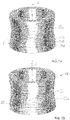
- Figs. 5A and 5B depict how the outer contour 22, i.e. the form of the engagement surface 22c, of the neck 18 is formed.
- Fig. 5A shows how the outer contour 22 would look like if manufactured out of different oval rings 24 with a certain thickness.
- a first oval ring 24A would be placed on the bottom.
- a second, identical oval ring 24B would be placed on top of the first oval ring 24A but with an angular offset with respect to the longitudinal axis A.
- the next oval ring 24C is placed on the oval ring 24B with the same angular offset with respect to the longitudinal axis A and so on.
- the actual outer contour can be described thereby that oval rings 24 having an infinitesimal small thickness are placed on top of each other with a constant angular offset with respect to the longitudinal axis A and the previously and subsequently placed respective oval ring 24.
- the outer contour 22 of the neck can be described in that an angular position of each of the oval contours is controlled by a helix 23 that is arranged along the longitudinal axis A of the neck 18.
- the continuous outer surface of the neck 18 can be described functionally as an ellipsoid 22 controlled by a helix 23 extending in the longitudinal direction A.
- the general shape of the rings 24 and therefore the contour 22 does not have to be oval, but could have other shapes as well. This results in a continuous outer surface with points being equidistant to the longitudinal axis A forming the helix 23.
- the inner contour 20 of the cap 14 is formed by correspondingly shaped rings having an inner surface shaped complementary to the outer shape of the neck 18, depicted by the oval rings 24.
- Figs. 6A to 8 show a structure to form a securing device 26 that interrupts the continuity of the outer circumferential surface of the neck 18.
- the securing device 26 is formed by multiple parallel valleys or grooves 26a arranged at least substantially in parallel to one another or in parallel to one another that are formed on the inner circumferential surface of the cap 14 and a plurality of correspondingly shaped elevations or peaks 26b formed on the outer circumferential surface of the neck 18.
- the securing device 26 is configured to provide multiple defined locking positions for the cap 14 relative to the neck 18 with each locking position providing an audible click and a tangible resistance when the cap is rotated into said locking position after the cap 14 is fully attached onto the neck 18.
- valley or groove 26a could be provided at the inner contour 20 of the cap 14, with also only one correspondingly shaped elevation or peak 26b formed on the outer circumferential surface of the neck 18.
- the securing device 26 may comprise one or more valleys or grooves 26a arranged at least substantially in parallel to one another or in parallel to one another at the inner circumferential surface of the cap 14.
- the securing device 26 may comprise one or more elevations or peaks 26b arranged at least substantially in parallel to one another or in parallel to one another the outer circumferential surface of the neck 18.
- the securing device 26 may be arranged at least substantially in parallel to at least one of the respective helices 21, 23.
- securing device 26' which comprises a groove or elevation that extends along a majority of the neck along a helix.
- Fig. 12B shows a further embodiment of the securing device 26".
- the securing device comprises a dome 26" or depression.
- the securing device 26" comprises a corresponding depression or dome on the inner circumferential surface of the cap 14. The dome 26" can be brought into engagement with the corresponding depression to form a form-fitting engagement to secure the cap 14 on the neck 18.
- a first embodiment of the neck 18 is shown.
- the outer circumferential surface or outer contour 22 has an oval cross-sectional shape. While the smallest diameter of the oval shape is 12.5 mm, the largest diameter of the oval shape is 13.5 mm. The measurements can vary depending on the size of the receptacle 10.
- the ratio between the smallest diameter of the oval shape and the largest diameter of the oval shape is selected in the range of 0.9 to 0.96, in particular 0.91 to 0.95, especially of 0.92 to 0.94.
- the ratio between the smallest diameter of the oval shape and the largest diameter of the oval shape can be 0.926.
- the neck 18 also has an inner circumferential surface 28 which defines an inner cross-sectional shape which is a circular shape.
- the inner circumferential surface 28 defines a passage 30 that leads to a volume 32 ( Fig. 9B ) defined by the container 12 to store a product, e.g. a beauty product.
- a second embodiment of the neck 18 is shown.
- the outer circumferential surface has a cross-sectional shape that is - like the embodiment shown in Figs. 8 to 9B - axially symmetrical, but - in contrast to the embodiment shown in Figs. 8 to 9B - has 3 largest outer diameters 34.
- the shown neck 18 has a cross sectional shape in the form of a hyperbolic trigon. This embodiment has the advantage that the cap 14 can be placed on the neck 18 in three different angular positions each being 120° apart from each other making it easier to attach the cap 14 onto the neck 18.
- the cap 14 further comprises a support structure 36 for an applicator (not shown).
- the support structure 36 extends along the longitudinal axis A of the cap 14 and is partly surrounded by the caps inner circumferential surface.
- a sealing 38 is located at the inner circumferential surface 28 of the neck 18. The sealing 38 is configured to seal against the support structure 36 when the cap 14 is attached to the neck 18 of the container 12.
- the convex shaped part of the of the engagement surface 22c engages the concave shaped part of the counter engagement surface 20c, similarly the concave shaped part of the engagement surface 22c engages the convex shaped part of the counter engagement surface 20c, and by rotating the cap 14 relative to the neck 18 to the cap is attached to the neck 18 of the container 12.
- the cap On rotating the cap 14 relative to the container 12, the cap not only engages the neck 18 in a form fitting engagement, but also in a press-fitting engagement in a radial direction between the inner circumferential surface of the passage 16 and the outer circumferential surface of the neck 18 to secure the cap 14 at the container 12.
- Use of a common thread would only produce a form-fitting engagement in the radial direction but no such press-fit.
Landscapes
- Engineering & Computer Science (AREA)
- Mechanical Engineering (AREA)
- Ceramic Engineering (AREA)
- Closures For Containers (AREA)
Priority Applications (6)
| Application Number | Priority Date | Filing Date | Title |
|---|---|---|---|
| EP21162751.8A EP4059854A1 (de) | 2021-03-16 | 2021-03-16 | Behälter |
| DE202022003114.9U DE202022003114U1 (de) | 2021-03-16 | 2022-02-11 | Gefäß |
| CN202280022032.4A CN117396407A (zh) | 2021-03-16 | 2022-02-11 | 容器 |
| PCT/EP2022/053344 WO2022194460A1 (en) | 2021-03-16 | 2022-02-11 | Receptacle |
| US18/282,464 US20240156236A1 (en) | 2021-03-16 | 2022-02-11 | Receptacle |
| EP22708496.9A EP4291497B1 (de) | 2021-03-16 | 2022-02-11 | Behälter |
Applications Claiming Priority (1)
| Application Number | Priority Date | Filing Date | Title |
|---|---|---|---|
| EP21162751.8A EP4059854A1 (de) | 2021-03-16 | 2021-03-16 | Behälter |
Publications (1)
| Publication Number | Publication Date |
|---|---|
| EP4059854A1 true EP4059854A1 (de) | 2022-09-21 |
Family
ID=74884825
Family Applications (2)
| Application Number | Title | Priority Date | Filing Date |
|---|---|---|---|
| EP21162751.8A Withdrawn EP4059854A1 (de) | 2021-03-16 | 2021-03-16 | Behälter |
| EP22708496.9A Active EP4291497B1 (de) | 2021-03-16 | 2022-02-11 | Behälter |
Family Applications After (1)
| Application Number | Title | Priority Date | Filing Date |
|---|---|---|---|
| EP22708496.9A Active EP4291497B1 (de) | 2021-03-16 | 2022-02-11 | Behälter |
Country Status (5)
| Country | Link |
|---|---|
| US (1) | US20240156236A1 (de) |
| EP (2) | EP4059854A1 (de) |
| CN (1) | CN117396407A (de) |
| DE (1) | DE202022003114U1 (de) |
| WO (1) | WO2022194460A1 (de) |
Citations (3)
| Publication number | Priority date | Publication date | Assignee | Title |
|---|---|---|---|---|
| GB361885A (en) * | 1929-05-30 | 1931-11-19 | British Dardelet Threadlock D | Containers with replaceable closures |
| US20080230505A1 (en) * | 2005-05-30 | 2008-09-25 | Cebal S.A.S. | Container With a Polygonal Neck |
| US20090028627A1 (en) * | 2005-07-06 | 2009-01-29 | L'oreal | Packaging and Applicator Device Including a Wiper Member |
Family Cites Families (3)
| Publication number | Priority date | Publication date | Assignee | Title |
|---|---|---|---|---|
| GB2267484B (en) * | 1992-04-30 | 1996-10-09 | Beeson & Sons Ltd | Container closure assembly |
| WO2006119026A2 (en) * | 2005-04-29 | 2006-11-09 | Mystic Tan, Inc. | Gantry tower spraying system with cartridge/receptacle assembly |
| GB2501061A (en) * | 2012-03-13 | 2013-10-16 | British American Tobacco Co | Container comprising cooperatively threaded base and lid |
-
2021
- 2021-03-16 EP EP21162751.8A patent/EP4059854A1/de not_active Withdrawn
-
2022
- 2022-02-11 EP EP22708496.9A patent/EP4291497B1/de active Active
- 2022-02-11 CN CN202280022032.4A patent/CN117396407A/zh active Pending
- 2022-02-11 DE DE202022003114.9U patent/DE202022003114U1/de active Active
- 2022-02-11 US US18/282,464 patent/US20240156236A1/en active Pending
- 2022-02-11 WO PCT/EP2022/053344 patent/WO2022194460A1/en not_active Ceased
Patent Citations (3)
| Publication number | Priority date | Publication date | Assignee | Title |
|---|---|---|---|---|
| GB361885A (en) * | 1929-05-30 | 1931-11-19 | British Dardelet Threadlock D | Containers with replaceable closures |
| US20080230505A1 (en) * | 2005-05-30 | 2008-09-25 | Cebal S.A.S. | Container With a Polygonal Neck |
| US20090028627A1 (en) * | 2005-07-06 | 2009-01-29 | L'oreal | Packaging and Applicator Device Including a Wiper Member |
Also Published As
| Publication number | Publication date |
|---|---|
| EP4291497B1 (de) | 2025-04-02 |
| US20240156236A1 (en) | 2024-05-16 |
| CN117396407A (zh) | 2024-01-12 |
| DE202022003114U1 (de) | 2024-12-13 |
| WO2022194460A1 (en) | 2022-09-22 |
| EP4291497A1 (de) | 2023-12-20 |
Similar Documents
| Publication | Publication Date | Title |
|---|---|---|
| US9125474B2 (en) | Applicator for applying a composition to the eyelashes or the eyebrows | |
| RU2410004C2 (ru) | Аппликатор для нанесения средства на брови или ресницы | |
| EP2211663B1 (de) | Mascaraapplikator | |
| JP5878923B2 (ja) | 睫毛に組成物を塗布するためのアプリケータ | |
| EP2205123B1 (de) | Mascaraapplikator | |
| CN1921784A (zh) | 配有轴向套插式帽件的流体产品分配器 | |
| KR102306530B1 (ko) | 속눈썹 및/또는 눈썹에 제품을 도포하기 위한 도포기 | |
| JP2006051350A (ja) | 物質を角質線維に塗布する器具 | |
| CN107529871B (zh) | 用于液体或糊状物涂覆器的擦拭装置 | |
| JP6531175B2 (ja) | 化粧用、メイクアップ用、またはケア用の製品をまつ毛および/または眉毛に塗布するためのアプリケータ | |
| WO2013034638A1 (en) | Applicator for applying a product to the eyelashes or eyebrows | |
| EP4291497B1 (de) | Behälter | |
| JP6254317B1 (ja) | 化粧用塗布具 | |
| EP0582361A1 (de) | Applikator zum Auftragen von Flüssigkeit mit Durchflusspinsel und Herstellung desselben | |
| US11375803B2 (en) | Mascara applicator | |
| EP3752025B1 (de) | Applikator zum auftragen eines kosmetikprodukts | |
| WO2017001291A1 (en) | Method for manufacturing a mascara brush | |
| JP6468935B2 (ja) | 塗布容器 | |
| US11317706B2 (en) | Brush for applying a cosmetic product to the eyelashes and/or eyebrows, comprising cutouts | |
| JP7118157B2 (ja) | 化粧品のアプリケーター用ワイパー装置 | |
| JP2018504177A (ja) | 睫毛および/または眉毛に化粧品、メーキャップまたはケア製品を塗布するためのアプリケータ | |
| EP3541236A1 (de) | Bürste zum auftragen eines produkts auf die wimpern und/oder augenbrauen | |
| US20180049542A1 (en) | Cosmetic applicator having fibres |
Legal Events
| Date | Code | Title | Description |
|---|---|---|---|
| PUAI | Public reference made under article 153(3) epc to a published international application that has entered the european phase |
Free format text: ORIGINAL CODE: 0009012 |
|
| STAA | Information on the status of an ep patent application or granted ep patent |
Free format text: STATUS: THE APPLICATION HAS BEEN PUBLISHED |
|
| AK | Designated contracting states |
Kind code of ref document: A1 Designated state(s): AL AT BE BG CH CY CZ DE DK EE ES FI FR GB GR HR HU IE IS IT LI LT LU LV MC MK MT NL NO PL PT RO RS SE SI SK SM TR |
|
| STAA | Information on the status of an ep patent application or granted ep patent |
Free format text: STATUS: THE APPLICATION IS DEEMED TO BE WITHDRAWN |
|
| 18D | Application deemed to be withdrawn |
Effective date: 20230322 |