EP4060093B1 - Surfaces tribologiquement améliorées pour contacts électriques - Google Patents
Surfaces tribologiquement améliorées pour contacts électriques Download PDFInfo
- Publication number
- EP4060093B1 EP4060093B1 EP21163067.8A EP21163067A EP4060093B1 EP 4060093 B1 EP4060093 B1 EP 4060093B1 EP 21163067 A EP21163067 A EP 21163067A EP 4060093 B1 EP4060093 B1 EP 4060093B1
- Authority
- EP
- European Patent Office
- Prior art keywords
- layer
- substrate
- intermediate layer
- electrical contact
- further metal
- Prior art date
- Legal status (The legal status is an assumption and is not a legal conclusion. Google has not performed a legal analysis and makes no representation as to the accuracy of the status listed.)
- Active
Links
Images

Classifications
-
- H—ELECTRICITY
- H01—ELECTRIC ELEMENTS
- H01R—ELECTRICALLY-CONDUCTIVE CONNECTIONS; STRUCTURAL ASSOCIATIONS OF A PLURALITY OF MUTUALLY-INSULATED ELECTRICAL CONNECTING ELEMENTS; COUPLING DEVICES; CURRENT COLLECTORS
- H01R13/00—Details of coupling devices of the kinds covered by groups H01R12/70 or H01R24/00 - H01R33/00
- H01R13/02—Contact members
- H01R13/03—Contact members characterised by the material, e.g. plating, or coating materials
-
- C—CHEMISTRY; METALLURGY
- C23—COATING METALLIC MATERIAL; COATING MATERIAL WITH METALLIC MATERIAL; CHEMICAL SURFACE TREATMENT; DIFFUSION TREATMENT OF METALLIC MATERIAL; COATING BY VACUUM EVAPORATION, BY SPUTTERING, BY ION IMPLANTATION OR BY CHEMICAL VAPOUR DEPOSITION, IN GENERAL; INHIBITING CORROSION OF METALLIC MATERIAL OR INCRUSTATION IN GENERAL
- C23C—COATING METALLIC MATERIAL; COATING MATERIAL WITH METALLIC MATERIAL; SURFACE TREATMENT OF METALLIC MATERIAL BY DIFFUSION INTO THE SURFACE, BY CHEMICAL CONVERSION OR SUBSTITUTION; COATING BY VACUUM EVAPORATION, BY SPUTTERING, BY ION IMPLANTATION OR BY CHEMICAL VAPOUR DEPOSITION, IN GENERAL
- C23C14/00—Coating by vacuum evaporation, by sputtering or by ion implantation of the coating forming material
- C23C14/06—Coating by vacuum evaporation, by sputtering or by ion implantation of the coating forming material characterised by the coating material
- C23C14/0623—Sulfides, selenides or tellurides
-
- C—CHEMISTRY; METALLURGY
- C23—COATING METALLIC MATERIAL; COATING MATERIAL WITH METALLIC MATERIAL; CHEMICAL SURFACE TREATMENT; DIFFUSION TREATMENT OF METALLIC MATERIAL; COATING BY VACUUM EVAPORATION, BY SPUTTERING, BY ION IMPLANTATION OR BY CHEMICAL VAPOUR DEPOSITION, IN GENERAL; INHIBITING CORROSION OF METALLIC MATERIAL OR INCRUSTATION IN GENERAL
- C23C—COATING METALLIC MATERIAL; COATING MATERIAL WITH METALLIC MATERIAL; SURFACE TREATMENT OF METALLIC MATERIAL BY DIFFUSION INTO THE SURFACE, BY CHEMICAL CONVERSION OR SUBSTITUTION; COATING BY VACUUM EVAPORATION, BY SPUTTERING, BY ION IMPLANTATION OR BY CHEMICAL VAPOUR DEPOSITION, IN GENERAL
- C23C14/00—Coating by vacuum evaporation, by sputtering or by ion implantation of the coating forming material
- C23C14/22—Coating by vacuum evaporation, by sputtering or by ion implantation of the coating forming material characterised by the process of coating
- C23C14/34—Sputtering
-
- C—CHEMISTRY; METALLURGY
- C23—COATING METALLIC MATERIAL; COATING MATERIAL WITH METALLIC MATERIAL; CHEMICAL SURFACE TREATMENT; DIFFUSION TREATMENT OF METALLIC MATERIAL; COATING BY VACUUM EVAPORATION, BY SPUTTERING, BY ION IMPLANTATION OR BY CHEMICAL VAPOUR DEPOSITION, IN GENERAL; INHIBITING CORROSION OF METALLIC MATERIAL OR INCRUSTATION IN GENERAL
- C23C—COATING METALLIC MATERIAL; COATING MATERIAL WITH METALLIC MATERIAL; SURFACE TREATMENT OF METALLIC MATERIAL BY DIFFUSION INTO THE SURFACE, BY CHEMICAL CONVERSION OR SUBSTITUTION; COATING BY VACUUM EVAPORATION, BY SPUTTERING, BY ION IMPLANTATION OR BY CHEMICAL VAPOUR DEPOSITION, IN GENERAL
- C23C2/00—Hot-dipping or immersion processes for applying the coating material in the molten state without affecting the shape; Apparatus therefor
- C23C2/04—Hot-dipping or immersion processes for applying the coating material in the molten state without affecting the shape; Apparatus therefor characterised by the coating material
-
- C—CHEMISTRY; METALLURGY
- C23—COATING METALLIC MATERIAL; COATING MATERIAL WITH METALLIC MATERIAL; CHEMICAL SURFACE TREATMENT; DIFFUSION TREATMENT OF METALLIC MATERIAL; COATING BY VACUUM EVAPORATION, BY SPUTTERING, BY ION IMPLANTATION OR BY CHEMICAL VAPOUR DEPOSITION, IN GENERAL; INHIBITING CORROSION OF METALLIC MATERIAL OR INCRUSTATION IN GENERAL
- C23C—COATING METALLIC MATERIAL; COATING MATERIAL WITH METALLIC MATERIAL; SURFACE TREATMENT OF METALLIC MATERIAL BY DIFFUSION INTO THE SURFACE, BY CHEMICAL CONVERSION OR SUBSTITUTION; COATING BY VACUUM EVAPORATION, BY SPUTTERING, BY ION IMPLANTATION OR BY CHEMICAL VAPOUR DEPOSITION, IN GENERAL
- C23C24/00—Coating starting from inorganic powder
- C23C24/02—Coating starting from inorganic powder by application of pressure only
- C23C24/06—Compressing powdered coating material, e.g. by milling
-
- C—CHEMISTRY; METALLURGY
- C23—COATING METALLIC MATERIAL; COATING MATERIAL WITH METALLIC MATERIAL; CHEMICAL SURFACE TREATMENT; DIFFUSION TREATMENT OF METALLIC MATERIAL; COATING BY VACUUM EVAPORATION, BY SPUTTERING, BY ION IMPLANTATION OR BY CHEMICAL VAPOUR DEPOSITION, IN GENERAL; INHIBITING CORROSION OF METALLIC MATERIAL OR INCRUSTATION IN GENERAL
- C23C—COATING METALLIC MATERIAL; COATING MATERIAL WITH METALLIC MATERIAL; SURFACE TREATMENT OF METALLIC MATERIAL BY DIFFUSION INTO THE SURFACE, BY CHEMICAL CONVERSION OR SUBSTITUTION; COATING BY VACUUM EVAPORATION, BY SPUTTERING, BY ION IMPLANTATION OR BY CHEMICAL VAPOUR DEPOSITION, IN GENERAL
- C23C28/00—Coating for obtaining at least two superposed coatings either by methods not provided for in a single one of groups C23C2/00 - C23C26/00 or by combinations of methods provided for in subclasses C23C and C25C or C25D
-
- C—CHEMISTRY; METALLURGY
- C23—COATING METALLIC MATERIAL; COATING MATERIAL WITH METALLIC MATERIAL; CHEMICAL SURFACE TREATMENT; DIFFUSION TREATMENT OF METALLIC MATERIAL; COATING BY VACUUM EVAPORATION, BY SPUTTERING, BY ION IMPLANTATION OR BY CHEMICAL VAPOUR DEPOSITION, IN GENERAL; INHIBITING CORROSION OF METALLIC MATERIAL OR INCRUSTATION IN GENERAL
- C23C—COATING METALLIC MATERIAL; COATING MATERIAL WITH METALLIC MATERIAL; SURFACE TREATMENT OF METALLIC MATERIAL BY DIFFUSION INTO THE SURFACE, BY CHEMICAL CONVERSION OR SUBSTITUTION; COATING BY VACUUM EVAPORATION, BY SPUTTERING, BY ION IMPLANTATION OR BY CHEMICAL VAPOUR DEPOSITION, IN GENERAL
- C23C28/00—Coating for obtaining at least two superposed coatings either by methods not provided for in a single one of groups C23C2/00 - C23C26/00 or by combinations of methods provided for in subclasses C23C and C25C or C25D
- C23C28/30—Coatings combining at least one metallic layer and at least one inorganic non-metallic layer
- C23C28/32—Coatings combining at least one metallic layer and at least one inorganic non-metallic layer including at least one pure metallic layer
-
- C—CHEMISTRY; METALLURGY
- C23—COATING METALLIC MATERIAL; COATING MATERIAL WITH METALLIC MATERIAL; CHEMICAL SURFACE TREATMENT; DIFFUSION TREATMENT OF METALLIC MATERIAL; COATING BY VACUUM EVAPORATION, BY SPUTTERING, BY ION IMPLANTATION OR BY CHEMICAL VAPOUR DEPOSITION, IN GENERAL; INHIBITING CORROSION OF METALLIC MATERIAL OR INCRUSTATION IN GENERAL
- C23C—COATING METALLIC MATERIAL; COATING MATERIAL WITH METALLIC MATERIAL; SURFACE TREATMENT OF METALLIC MATERIAL BY DIFFUSION INTO THE SURFACE, BY CHEMICAL CONVERSION OR SUBSTITUTION; COATING BY VACUUM EVAPORATION, BY SPUTTERING, BY ION IMPLANTATION OR BY CHEMICAL VAPOUR DEPOSITION, IN GENERAL
- C23C28/00—Coating for obtaining at least two superposed coatings either by methods not provided for in a single one of groups C23C2/00 - C23C26/00 or by combinations of methods provided for in subclasses C23C and C25C or C25D
- C23C28/30—Coatings combining at least one metallic layer and at least one inorganic non-metallic layer
- C23C28/34—Coatings combining at least one metallic layer and at least one inorganic non-metallic layer including at least one inorganic non-metallic material layer, e.g. metal carbide, nitride, boride, silicide layer and their mixtures, enamels, phosphates and sulphates
- C23C28/345—Coatings combining at least one metallic layer and at least one inorganic non-metallic layer including at least one inorganic non-metallic material layer, e.g. metal carbide, nitride, boride, silicide layer and their mixtures, enamels, phosphates and sulphates with at least one oxide layer
-
- C—CHEMISTRY; METALLURGY
- C23—COATING METALLIC MATERIAL; COATING MATERIAL WITH METALLIC MATERIAL; CHEMICAL SURFACE TREATMENT; DIFFUSION TREATMENT OF METALLIC MATERIAL; COATING BY VACUUM EVAPORATION, BY SPUTTERING, BY ION IMPLANTATION OR BY CHEMICAL VAPOUR DEPOSITION, IN GENERAL; INHIBITING CORROSION OF METALLIC MATERIAL OR INCRUSTATION IN GENERAL
- C23C—COATING METALLIC MATERIAL; COATING MATERIAL WITH METALLIC MATERIAL; SURFACE TREATMENT OF METALLIC MATERIAL BY DIFFUSION INTO THE SURFACE, BY CHEMICAL CONVERSION OR SUBSTITUTION; COATING BY VACUUM EVAPORATION, BY SPUTTERING, BY ION IMPLANTATION OR BY CHEMICAL VAPOUR DEPOSITION, IN GENERAL
- C23C4/00—Coating by spraying the coating material in the molten state, e.g. by flame, plasma or electric discharge
- C23C4/04—Coating by spraying the coating material in the molten state, e.g. by flame, plasma or electric discharge characterised by the coating material
- C23C4/06—Metallic material
- C23C4/08—Metallic material containing only metal elements
-
- H—ELECTRICITY
- H01—ELECTRIC ELEMENTS
- H01R—ELECTRICALLY-CONDUCTIVE CONNECTIONS; STRUCTURAL ASSOCIATIONS OF A PLURALITY OF MUTUALLY-INSULATED ELECTRICAL CONNECTING ELEMENTS; COUPLING DEVICES; CURRENT COLLECTORS
- H01R43/00—Apparatus or processes specially adapted for manufacturing, assembling, maintaining, or repairing of line connectors or current collectors or for joining electric conductors
- H01R43/16—Apparatus or processes specially adapted for manufacturing, assembling, maintaining, or repairing of line connectors or current collectors or for joining electric conductors for manufacturing contact members, e.g. by punching and by bending
-
- C—CHEMISTRY; METALLURGY
- C23—COATING METALLIC MATERIAL; COATING MATERIAL WITH METALLIC MATERIAL; CHEMICAL SURFACE TREATMENT; DIFFUSION TREATMENT OF METALLIC MATERIAL; COATING BY VACUUM EVAPORATION, BY SPUTTERING, BY ION IMPLANTATION OR BY CHEMICAL VAPOUR DEPOSITION, IN GENERAL; INHIBITING CORROSION OF METALLIC MATERIAL OR INCRUSTATION IN GENERAL
- C23C—COATING METALLIC MATERIAL; COATING MATERIAL WITH METALLIC MATERIAL; SURFACE TREATMENT OF METALLIC MATERIAL BY DIFFUSION INTO THE SURFACE, BY CHEMICAL CONVERSION OR SUBSTITUTION; COATING BY VACUUM EVAPORATION, BY SPUTTERING, BY ION IMPLANTATION OR BY CHEMICAL VAPOUR DEPOSITION, IN GENERAL
- C23C4/00—Coating by spraying the coating material in the molten state, e.g. by flame, plasma or electric discharge
- C23C4/04—Coating by spraying the coating material in the molten state, e.g. by flame, plasma or electric discharge characterised by the coating material
- C23C4/06—Metallic material
-
- C—CHEMISTRY; METALLURGY
- C25—ELECTROLYTIC OR ELECTROPHORETIC PROCESSES; APPARATUS THEREFOR
- C25D—PROCESSES FOR THE ELECTROLYTIC OR ELECTROPHORETIC PRODUCTION OF COATINGS; ELECTROFORMING; APPARATUS THEREFOR
- C25D5/00—Electroplating characterised by the process; Pretreatment or after-treatment of workpieces
- C25D5/10—Electroplating with more than one layer of the same or of different metals
- C25D5/12—Electroplating with more than one layer of the same or of different metals at least one layer being of nickel or chromium
-
- C—CHEMISTRY; METALLURGY
- C25—ELECTROLYTIC OR ELECTROPHORETIC PROCESSES; APPARATUS THEREFOR
- C25D—PROCESSES FOR THE ELECTROLYTIC OR ELECTROPHORETIC PRODUCTION OF COATINGS; ELECTROFORMING; APPARATUS THEREFOR
- C25D7/00—Electroplating characterised by the article coated
-
- C—CHEMISTRY; METALLURGY
- C25—ELECTROLYTIC OR ELECTROPHORETIC PROCESSES; APPARATUS THEREFOR
- C25D—PROCESSES FOR THE ELECTROLYTIC OR ELECTROPHORETIC PRODUCTION OF COATINGS; ELECTROFORMING; APPARATUS THEREFOR
- C25D7/00—Electroplating characterised by the article coated
- C25D7/06—Wires; Strips; Foils
- C25D7/0614—Strips or foils
Definitions
- the present invention relates to a method for producing an electrical contact, an electrical contact and the use of an electrical contact for plug connections.
- Electrical contacts have contact surfaces that are usually made of an electrically conductive material, preferably a metallic conductor. Electrical contacts preferably consist of a rigid end and a resilient end that applies the contact force, with both ends usually having a metallic coating that is different from the base material.
- This coating can be produced, for example, by immersion in a molten metal, by physical and/or chemical vapor deposition, or by electroless or electrolytic coating. Frequently used coating materials are gold, silver, palladium, platinum, rhodium, ruthenium, nickel, tin, copper, zinc, or alloys thereof.
- desired properties of the electrical contact surface can be achieved, such as improved corrosion resistance, improved wear behavior, ensuring stable electrical contact resistance, and/or a reduction in the coefficient of friction.
- contact lubricants are often used for electrical contact surfaces.
- Chudnovsky 2005; Lubrication of electrical contacts; In Proceedings of the Fifty-First IEEE Holm Conference on Electrical Contacts; 2005; pp. 107-114; IEEE ) a number of corresponding contact lubricants are known, whereby a distinction is made between mineral oils, greases, synthetically produced lubricants based on synthetically produced compounds, such as polyphenyl ether (PPE) and perfluorinated polyether (PFPE), as well as solid lubricants such as graphite, molybdenum disulfide, polytetrafluoroethylene (PTFE) and dispersions of solid lubricants and the aforementioned liquid/pasty lubricants.
- PPE polyphenyl ether
- PFPE perfluorinated polyether
- solid lubricants such as graphite, molybdenum disulfide, polytetrafluoroethylene (PTFE) and dispersions of solid lubricants and
- a silver-graphite dispersion coating is known, in which graphite is incorporated into a metal matrix as a solid lubricant by means of galvanic dispersion deposition.
- the disadvantage of this process is the lack of flexibility due to the limitation to certain electrolyte compositions and the metals that can be deposited by galvanic dispersion deposition.
- EP 3633256 A1 relates to a threaded connection with excellent misalignment resistance and high torque strength and a method for producing the threaded connection.
- US 2021/066834 A1 relates to a low insertion force contact comprising a conductive base layer extending to a mating end.
- a silver layer is provided on the conductive base layer, and a silver sulfide surface layer forms a solid lubricant directly on the silver layer.
- RU 2364781 C1 concerns threaded connections for steel pipes.
- the first layer applied is made of a Sn-Bi alloy or a Sn-Bi-Cu alloy formed on the contact surface of at least one nipple and one coupling.
- the JP 2001 287079 A relates to a steel wire for arc welding, which is characterized by the fact that it has a lubricant on its surface.
- the DE 10 2018 005348 A1 relates to a silver electrolyte for depositing silver layers on substrates, wherein the electrolyte and the deposited layer comprise at least one solid component.
- the object of the present invention is to provide a method for producing an electrical contact and an electrical contact that has a favorable coefficient of friction, high wear resistance, and good contact resistance.
- the method should also be time-saving and cost-effective.
- the object is achieved by a method for producing an electrical contact according to patent claim 1, an electrical contact according to patent claim 5, the use of an electrical contact according to patent claim 15.
- the tribological properties of an electrical contact can be significantly improved without significantly negatively affecting the electrical properties, in particular the contact resistance.
- the improved tribological properties compared to the prior art simultaneously lead to a reduction in wear, so that the electrical contacts according to the invention, in particular when used for plug-in contacts, can withstand higher mating cycles while maintaining stable contact resistance values.
- the application process can be carried out particularly easily, so that, for example, auxiliary materials such as binders and similar materials are not required, which has a particularly advantageous effect on the costs of the process according to the invention.
- the electrical contacts according to the invention exhibit increased temperature resistance, thus enabling use at higher temperatures and/or under vacuum of these and/or the electrical contacts produced therefrom. Furthermore, the electrical contacts can withstand high contact pressures without losing their positive tribological properties.
- solid lubricant refers to a lubricant that is in a solid state and is used in this state.
- the term "average particle size (d50)" means that 50% of the particles of a solid component have a diameter smaller than the specified value.
- the d90 value indicates that 90% of the particles of a solid component have a diameter smaller than the specified value.
- the term "metallic surface” refers to the surface of a metallic substrate.
- the substrate may consist of a pure metal or an alloy.
- metal-containing surface in the context of the present invention refers to a metal-containing surface that is applied directly to a substrate, in particular a non-metal substrate.
- the surfaces of electrically non-conductive materials such as plastics, glass, oxides, semiconductors, or ceramics are metallized.
- Such surfaces are, for example, nickel-plated, galvanized, tin-plated, copper-plated, chrome-plated, or coated with other materials, such as aluminum and magnesium alloys, iron, steel, or technical alloys of these metals, or with precious metals such as gold or silver or their alloys.
- Preferred alloys for coating substrate surfaces are copper, zinc, alloys of zinc/iron, zinc/manganese, zinc/cobalt, or tin, alloys of tin/copper, tin/zinc, tin/lead, tin/silver, and tin/bismuth.
- Various metallization processes are known, for example, from DE 102016222943 B known.
- intermediate layer refers to a layer arranged on a substrate, wherein one or more additional metal layers may be arranged between the substrate and the intermediate layer.
- the sliding layer if present, is applied to the intermediate layer.
- the substrate is a metallic substrate.
- the metallic substrate is preferably formed from copper, iron, zinc, tin, aluminum, and/or alloys thereof. Alloys are preferably bronze or brass. More preferably, the metallic substrate is formed from copper, iron, and/or an alloy thereof.
- the substrate is a non-metallic substrate.
- the non-metallic substrate is formed from plastic, glass, oxides, semiconductors, and/or ceramics; more preferably, the non-metallic substrate is formed from plastic or ceramic.
- the non-metallic substrate has a metallized surface.
- the substrate has an intermediate layer.
- the sliding layer is applied to the intermediate layer.
- the intermediate layer is formed from one of the metals selected from the group comprising gold (Au), copper (Cu), nickel (Ni), palladium (Pd), platinum (Pt), rhodium (Rh), ruthenium (Ru), silver (Ag), zinc (Zn), tin (Sn) and/or an alloy thereof.
- the intermediate layer is a tin or silver layer.
- the intermediate layer is preferably applied by electroplating, immersion in a metallic melt, thermal spraying, physical vapor deposition, hot-dip tinning, or chemical vapor deposition.
- Thermal spraying processes include flame spraying, laser spraying, plasma spraying, and other related processes.
- the intermediate layer is more preferably applied by electroplating or hot-dip tinning.
- the intermediate layer is preferably applied using an electroless process. Electroless processes are known in the art.
- the substrate has an intermediate layer and at least two further metal layers, wherein the at least two further metal layers are arranged between the substrate and the intermediate layer, wherein the at least two further metal layers are preferably formed from one of the metals selected from the group comprising gold (Au), copper (Cu), nickel (Ni), palladium (Pd), platinum (Pt), rhodium (Rh), ruthenium (Ru), silver (Ag), zinc (Zn), tin (Sn) and/or an alloy thereof.
- the sliding layer is applied to the intermediate layer.
- Alloys can be, for example, Cu-Sn-Zn alloys, preferably white bronze.
- the intermediate layer and the metal layers may also contain other inorganic components such as phosphorus, boron, antimony, tellurium, cobalt, indium, iron, tungsten, or mixtures thereof in a proportion of up to 0.001 to 15 wt.%, and preferably 0.01 to 10 wt.%, based on the total mass of the respective layer. Hard metals such as tungsten may also be added.
- the intermediate layer and the metal layers contain, in addition to the aforementioned metals, 0.01 to 1 wt.% and preferably 0.05 to 0.5 wt.% based on the total mass of the respective layer, further inorganic components such as phosphorus, boron, antimony, tellurium, cobalt, indium, iron, tungsten or mixtures thereof.
- further inorganic components such as phosphorus, boron, antimony, tellurium, cobalt, indium, iron, tungsten or mixtures thereof.
- step a) comprises, preferably consists of, the following steps: providing a substrate and applying an intermediate layer.
- step a) comprises, preferably consists of, the following steps: providing a substrate, applying at least one further metal layer, preferably a further first metal layer and a further second metal layer, and then applying an intermediate layer.
- step a) comprises, preferably consists of, the following steps: providing a substrate, applying at least three further metal layers and then applying an intermediate layer.
- the metal layers can be applied by electroplating, immersion in a metallic melt, thermal spraying, physical vapor deposition, hot-dip tinning, or chemical vapor deposition.
- Thermal spraying processes include flame spraying, laser spraying, plasma spraying, and other related processes.
- the intermediate layer is preferably applied by electroplating or hot-dip tinning.
- the metal layers can also preferably be applied using electroless processes.
- the solid lubricant is selected from the group consisting of sulfides, selenides, and/or tellurides. Further preferably, the solid lubricant is selected from the group consisting of WS 2 , MoS 2 , NbS 2 , NbSe 2 , TaS 2 , MoTe 2 , MoSe 2 , WTe 2 , WSe 2 , HfS 2 , SnS 2 , Bi 2 S 3 , Sb 2 S 3 , and/or mixtures thereof.
- the solid lubricant is selected from the group consisting of graphite, graphite oxide, graphite fluoride, phthalocyanine, organic polymers, in particular polytetrafluoroethylene (PTFE) and/or metal complexes derived therefrom.
- PTFE polytetrafluoroethylene
- the sliding layer can be applied in a variety of ways.
- the sliding layer can be applied mechanically to the intermediate layer by rubbing, polishing, and/or buffing.
- the sliding layer can also be sputtered onto the intermediate layer.
- the particulate solid lubricant can be sprayed onto the intermediate layer using a gaseous carrier medium, such as air.
- a gaseous carrier medium such as air.
- the adhesion can be precisely adjusted using the spray parameters, such as pressure.
- the sliding layer can be applied to the intermediate layer, optionally in the presence of additives and/or fillers, via a drum washer or using vibrating vessels.
- the invention relates to an electrical contact obtainable by the method according to one of claims 1 to 4, comprising a substrate (2), wherein the substrate (2) has a metallic and/or metallized surface, and at least one on the metallic and/or metallized surface of the substrate (2) arranged sliding layer (6) which consists of a solid lubricant, wherein the electrical contact is an electrical plug contact, and wherein the sliding layer (6) has a layer thickness of 0.01 ⁇ m to 4 ⁇ m, wherein the solid lubricant is selected from the group consisting of sulfides, selenides and/or tellurides.
- the electrical contact is an electrical plug contact.
- the substrate has an intermediate layer arranged on the metallic and/or metallized surface of the substrate.
- the intermediate layer is preferably formed from one of the metals selected from the group comprising gold (Au), copper (Cu), nickel (Ni), palladium (Pd), platinum (Pt), rhodium (Rh), ruthenium (Ru), silver (Ag), zinc (Zn), tin (Sn), and/or an alloy thereof.
- the sliding layer is arranged on the intermediate layer.
- the substrate has at least one further metal layer arranged on the metallic and/or metallized surface of the substrate.
- the at least one further metal layer is preferably formed from one of the metals selected from the group comprising gold (Au), copper (Cu), nickel (Ni), palladium (Pd), platinum (Pt), rhodium (Rh), ruthenium (Ru), silver (Ag), zinc (Zn), tin (Sn) and/or an alloy thereof.
- An intermediate layer is arranged on the at least one further metal layer, wherein the intermediate layer is preferably formed from one of the metals selected from the group comprising gold (Au), copper (Cu), nickel (Ni), palladium (Pd), platinum (Pt), rhodium (Rh), ruthenium (Ru), silver (Ag), zinc (Zn), tin (Sn) and/or an alloy thereof.
- the sliding layer is arranged on the intermediate layer.
- the substrate has at least one first further metal layer arranged on the metallic and/or metallized surface of the substrate, wherein the at least one first further metal layer is preferably formed from one of the metals selected from the group comprising gold (Au), copper (Cu), nickel (Ni), palladium (Pd), platinum (Pt), rhodium (Rh), ruthenium (Ru), silver (Ag), zinc (Zn), tin (Sn) and/or an alloy thereof, wherein a second further metal layer is arranged on the first further metal layer, wherein the at least one second further metal layer is preferably formed from one of the metals selected from the group comprising gold (Au), copper (Cu), nickel (Ni), palladium (Pd), platinum (Pt), rhodium (Rh), ruthenium (Ru), silver (Ag), zinc (Zn), tin (Sn) and/or an alloy thereof, and wherein the at least one second further An intermediate layer is arranged on the metal layer,
- the substrate is a metallic substrate.
- the metallic substrate is formed from copper, iron, zinc, tin, aluminum, and/or alloys thereof. Alloys are preferably bronze or brass. More preferably, the metallic substrate is formed from copper, iron, and/or an alloy thereof.
- the substrate is a non-metallic substrate.
- the non-metallic substrate is preferably made of plastic, glass, oxides, semiconductors, and/or ceramics; more preferably, the substrate is made of plastic or ceramics.
- the solid lubricant is selected from the group consisting of WS 2 , MoS 2 , NbS 2 , NbSe 2 , TaS 2 , MoTe 2 , MoSe 2 , WTe 2 , WSe 2 , HfS 2 , SnS 2 , Bi 2 S 3 , Sb 2 S 3 and/or mixtures thereof.
- the solid lubricant is selected from the group consisting of graphite, graphite oxide, graphite fluoride, phthalocyanine, organic polymers, in particular polytetrafluoroethylene (PTFE) and/or metal complexes derived therefrom.
- PTFE polytetrafluoroethylene
- the sliding layer of the electrical contact must not exceed a maximum layer thickness, as this can negatively impact the contact resistance.
- the sliding layer has a maximum layer thickness of 4 ⁇ m, preferably a maximum layer thickness of 3 ⁇ m, more preferably a maximum layer thickness of 2 ⁇ m, even more preferably a maximum layer thickness of 1 ⁇ m, and most preferably 0.01 ⁇ m - 1 ⁇ m.
- the layer thickness of the sliding layer is from 10 nm to 500 nm, preferably from 50 nm to 500 nm.
- the solid lubricant preferably contains a finely dispersed solid component with an average particle size (d50) of 10 nm - 100 ⁇ m, preferably with an average particle size (d50) of 50 nm - 75 ⁇ m, more preferably with an average particle size (d50) of 100 nm - 50 ⁇ m, even more preferably with an average particle size (d50) of 500 nm - 35 ⁇ m, and even more preferably with an average particle size (d50) of 1 ⁇ m - 20 ⁇ m.
- an average particle size (d50) of 10 nm - 100 ⁇ m preferably with an average particle size (d50) of 50 nm - 75 ⁇ m, more preferably with an average particle size (d50) of 100 nm - 50 ⁇ m, even more preferably with an average particle size (d50) of 500 nm - 35 ⁇ m, and even more preferably with an average particle size (d50) of 1 ⁇ m - 20 ⁇
- the sliding layer completely covers the underlying substrate or intermediate layer to achieve the tribological advantages described. According to a preferred embodiment, the sliding layer completely covers the underlying substrate or intermediate layer.
- the sliding layer at least partially covers the underlying substrate or intermediate layer.
- the substrate or intermediate layer is structured; and/or the sliding layer that at least partially covers the substrate or intermediate layer is structured.
- the friction coefficient of the electrical contact is in the range of 0.02 - 0.90, preferably 0.10 - 0.87, and more preferably 0.17 - 0.85.
- the friction coefficient remains constant over 1000 mating cycles.
- the contact resistance of the electrical contact is in the range of 0.1 - 60 mOhm, preferably 0.6 - 50 mOhm, more preferably 0.7 - 48.5 mOhm, even more preferably 0.8 - 40 mOhm and even more preferably 0.8 - 35 mOhm.
- the contact resistance remains constant over 1000 mating cycles.
- the solid lubricant forming the sliding layer is selected from the group consisting of sulfides, selenides, tellurides.
- the solid lubricant is selected from the group consisting of WS 2 , MoS 2 , NbS 2 , NbSe 2 , TaS 2 , MoTe 2 , MoSe 2 , WTe 2 , WSe 2 , HfS 2 , SnS 2 , Bi 2 S 3 , Sb 2 S 3 and/or mixtures thereof.
- the sulfides WS 2 and MoS 2 are particularly preferred because they have a high affinity for metal surfaces and therefore form a strong bond to them.
- Tungsten disulfide in particular has the further advantage that the particles have almost no interaction with each other, so that when tungsten disulfide is used as a solid lubricant, very thin sliding layers can be created on the intermediate layer of the electrical contact.
- the solid lubricant can be selected from the group consisting of graphite, graphite oxide, graphite fluoride, phthalocyanine, organic polymers, in particular polytetrafluoroethylene (PTFE), and/or metal complexes derived therefrom.
- PTFE polytetrafluoroethylene
- Another aspect concerns the use of a solid lubricant to adjust a friction coefficient of surfaces for electrical contacts.
- the solid lubricant is selected from the group consisting of sulfides, selenides and/or tellurides; or the solid lubricant is selected from the group consisting of WS 2 , MoS 2 , NbS 2 , NbSe 2 , TaS 2 , MoTe 2 , MoSe 2 , WTe 2 , WSe 2 , HfS 2 , SnS 2 , Bi 2 S 3 , Sb 2 S 3 and/or mixtures thereof; or the solid lubricant is selected from the group consisting of graphite, graphite oxide, graphite fluoride, phthalocyanine, organic polymers, in particular polytetrafluoroethylene (PTFE) and/or metal complexes derived therefrom.
- PTFE polytetrafluoroethylene
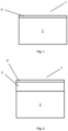
- Figure 1 shows a first embodiment of the electrical contact (1) according to the invention, which comprises a substrate (2), which in this case consists of brass (CuZn39Pb2).
- a sliding layer (6) was applied to this substrate (2).
- the sliding layer (6) was applied by rubbing tungsten disulfide particles onto the metallic surface of the substrate (2) with a cellulose cloth.
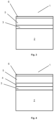
- Figure 2 shows a second embodiment of the electrical contact (1) according to the invention, which comprises a substrate (2), which in this case consists of brass (CuZn39Pb2), as well as an intermediate layer (5) and a sliding layer (6) which was applied to the intermediate layer (5).
- a layer of pure silver (5) with a layer thickness of 5 ⁇ m was first applied by electroplating to the metallic surface of the substrate (2), so that the intermediate layer (5) consisting of silver was created.
- the sliding layer (6) was then applied to the intermediate layer (5) by rubbing tungsten disulfide particles onto the intermediate layer (5) with a cellulose cloth. This was recognizable in the form of a discoloration of the silver layer arranged underneath, which represents the intermediate layer (5).
- a third embodiment of the electrical contact (1) which comprises a substrate (2), which in this case consists of brass (CuZn39Pb2), as well as a first further metal layer (3), an intermediate layer (5) and a sliding layer (6) which has been applied to the intermediate layer (5).
- a layer of copper which represents the first further metal layer (3)
- a layer of pure silver (5) with a layer thickness of 5 ⁇ m was applied to the metallic surface of the substrate (2) by electroplating, so that the intermediate layer (5) consisting of silver was created.
- the sliding layer (6) was then applied to the intermediate layer (5) by rubbing tungsten disulfide particles with a cellulose cloth, which was recognizable in the form of a discoloration of the underlying silver layer, which represents the intermediate layer (5).
- a layer of pure nickel which represents the second additional metal layer (4), was electroplated onto the copper layer (3) with a layer thickness of 2 ⁇ m, and then a layer of pure tin, which represents the intermediate layer (5), was electroplated with a layer thickness of 5 ⁇ m.
- the sliding layer (6) was then applied to the intermediate layer (5) by rubbing tungsten disulfide particles onto it with a cellulose cloth. This was noticeable in the form of a discoloration of the tin layer (5) arranged underneath.
- brass sheets material: CuZn39Pb2 from Metaq GmbH with dimensions of 75 mm x 17 mm x 1 mm and bronze balls (material: CuSn6) from KUGELPOMPEL HSI-Solutions GmbH with a diameter of 3 mm were used, which were then electroplated. Both the brass sheets and the bronze balls were first copper-plated and then coated with a layer of pure silver. They were thoroughly rinsed with water between each step.
- the bronze balls were coated analogously as drum goods, first with a 2 ⁇ m thick copper layer and then with a 5 ⁇ m thick silver layer.
- the coated brass sheets, EB1 and VB1 were mounted in a test rig simulating mating cycles and rubbed with the coated bronze balls. A weight of 1.0 N was applied to the ball. This ball rubbed against the coated brass sheet with the selected force over a distance of 3 mm at a frequency of 1 Hz. This test was repeated for 1,000 cycles. During the test, the friction force was measured using a U9C load cell (HBM). In addition, the contact resistance at the contact between the coated brass sheet and the ball was measured after each cycle. The contact resistance was measured using the four-wire method with a 2750/E digital multimeter (Keithley).
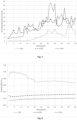
- Fig. 5 The results of the contact resistance measurements are shown.
- the contact resistance remained very stable in the range of 0.8 mOhm after more than 1000 mating cycles, whereas the Reference sheets, VB1, showed slightly higher contact resistance values.
- wear could be significantly reduced by treatment with the tungsten disulfide particles.
- Fig. 5 As can be seen, the brass sheets coated according to the invention (EB1) were able to withstand over 1000 mating cycles, whereas the untreated brass sheets (VB1) showed severe wear after only 200 mating cycles, manifesting as partial abrasion. The test was therefore discontinued after 200 mating cycles.
- Example 2 brass sheets (material: CuZn39Pb2; F49 (hard)) from Metaq GmbH measuring 75 mm x 17 mm x 1 mm and bronze balls (material: CuSn6) from KUGELPOMPEL HSI-Solutions GmbH with a diameter of 3 mm were used, which were then electroplated.
- the brass sheets and the bronze balls were first copper-plated and then coated with an intermediate layer of nickel and tin. They were thoroughly rinsed with water between each step.
- the galvanization of the brass sheets and the bronze balls comprised the following steps: degreasing of the substrates, etching of copper with a bath of sulphuric acid, complexing agent-free copper activation and treatment with bright copper bath was carried out according to the procedures described in the DE 10 2018005 352 and DE 10 2018 005 348 described.
- the nickel plating was then carried out in a nickel bath with a Watts nickel electrolyte (HSO Ni 110; manufacturer: HSO Herbert Schmidt GmbH & Co. KG, Solingen) according to known methods.
- HSO Ni 110 manufacturer: HSO Herbert Schmidt GmbH & Co. KG, Solingen
- the tin layer was then deposited from a matte tin electrolyte (SLOTOTIN 40; manufacturer: Dr.-Ing. Max Schlötter GmbH & Co. KG, Geislingen), which contained tin(II) methanesulfonate as tin salt, using known methods.
- SLOTOTIN 40 matte tin electrolyte
- inventive example 2 inventive example 2
- inventive example 3 inventive example 3
- the amounts of tungsten disulfide particles were varied so that two different layer thicknesses, EB2 and EB3, were produced and analyzed.
- the bronze balls were coated analogously as drum goods, first with a 2 ⁇ m thick copper layer, then with a 2 ⁇ m thick nickel layer and finally with a 5 ⁇ m thick tin layer.
- the coated brass sheets, EB2, EB3, and VB2 were mounted in a test rig simulating mating cycles and rubbed with the coated bronze balls. A weight of 1.0 N was applied to the ball. The ball rubbed against the coated brass sheet with the selected force over a distance of 3 mm at a frequency of 1 Hz. This was repeated for 50 cycles. During the test, the friction force was measured using a U9C load cell (HBM). In addition, the contact resistance at the contact between the coated brass sheet and the ball was measured after each cycle. The contact resistance was measured using the four-wire method with a 2750/E digital multimeter (Keithley).
- Fig. 7 The results of the contact resistance measurements are shown.
- the contact resistance of the samples with a higher amount of tungsten disulfide (EB3) increased from 5 mOhm to 50 mOhm.
- the contact resistance increased from 5 mOhm to 30 mOhm after more than 50 mating cycles.
- the chemical composition of the near-surface region was determined semiquantitatively using energy-dispersive X-ray spectroscopy. For this purpose, measurements were performed on the samples using an X-Flash Detector 410-M (Bruker AXS Microanalysis GmbH), which was installed in a JSM-6610 LV electron microscope (manufacturer: JEOL), with excitation voltages of 10 kV and 20 kV. An area of approximately 1 mm2 was analyzed in each case around the areas used to determine the contact resistance and the friction coefficient. Each area was analyzed using both excitation voltage settings. The measurements were evaluated using the Esprit software (Bruker).
Landscapes
- Chemical & Material Sciences (AREA)
- Engineering & Computer Science (AREA)
- Metallurgy (AREA)
- Organic Chemistry (AREA)
- Chemical Kinetics & Catalysis (AREA)
- Materials Engineering (AREA)
- Mechanical Engineering (AREA)
- Inorganic Chemistry (AREA)
- Manufacturing & Machinery (AREA)
- Physics & Mathematics (AREA)
- Plasma & Fusion (AREA)
- Electrochemistry (AREA)
- Other Surface Treatments For Metallic Materials (AREA)
Claims (15)
- Procédé de fabrication d'un contact électrique enfichable (1), comprenant les étapesa) de fourniture d'un substrat, dans lequel le substrat présente une surface métallique et/ou métallisée, etb) d'application d'une couche de glissement sur la surface métallique et/ou métallisée du substrat (2), dans lequel la couche de glissement (6) présente une épaisseur de 0,01 µm à 4 µm,dans lequel la couche de glissement (6) est appliquée par frottement mécanique, polissage et/ou flottement d'un lubrifiant solide ; oudans lequel la couche de glissement (6) est appliquée par pulvérisation d'un lubrifiant solide ; oudans lequel la couche de glissement (6) est appliquée par pulvérisation d'un lubrifiant solide avec utilisation d'un gaz porteur ; oudans lequel la couche de glissement (6) est appliquée par application d'un lubrifiant solide au moyen d'un laveur à tambour.
- Procédé selon la revendication 1, dans lequel le substrat (2) présente une couche intermédiaire (5), dans lequel la couche intermédiaire (5) est appliquée de préférence par galvanotechnique, par immersion dans une masse métallique fondue, par des procédés de pulvérisation thermique, par des procédés de dépôt physique en phase vapeur, par étamage à chaud ou par des procédés de dépôt chimique en phase vapeur, de manière davantage préférée par galvanotechnique ou par étamage à chaud sur le substrat (2), et dans lequel la couche de glissement est appliquée sur la couche intermédiaire (5).
- Procédé selon la revendication 2, dans lequel ledit substrat (2) présente au moins une autre couche métallique (3), dans lequel l'au moins une autre couche métallique (3) est disposée entre ledit substrat (2) et ladite couche intermédiaire (5), dans lequel l'au moins une autre couche métallique (3) est de préférence formée de l'un des métaux choisis dans le groupe comprenant l'or (Au), le cuivre (Cu), le nickel (Ni), le palladium (Pd), le platine (Pt), le rhodium (Rh), le ruthénium (Ru), l'argent (Ag), le zinc (Zn), l'étain (Sn) et/ou un alliage de ceux-ci ; et/oudans lequel le substrat (2) présente au moins deux autres couches métalliques (3, 4), dans lequel les au moins deux autres couches métalliques (3, 4) sont disposées entre le substrat (2) et la couche intermédiaire (5), dans lequel les au moins deux autres couches métalliques (3, 4) sont de préférence formées à partir de l'un des métaux choisis dans le groupe comprenant l'or (Au), le cuivre (Cu), le nickel (Ni), le palladium (Pd), le platine (Pt), le rhodium (Rh), le ruthénium (Ru), l'argent (Ag), le zinc (Zn), l'étain (Sn) et/ou un alliage de ceux-ci ; et/oudans lequel la couche intermédiaire (5) est une couche d'étain ou d'argent.
- Procédé selon l'une quelconque des revendications précédentes, dans lequel l'étape a) comprend les étapes suivantes :la fourniture d'un substrat (2) et l'application d'une couche intermédiaire (5) ; oula fourniture d'un substrat (2), l'application d'au moins une autre couche métallique (3), de préférence d'une autre première couche métallique (3) et d'une autre seconde couche métallique (4), puis l'application d'une couche intermédiaire (5) ; oula mise à disposition d'un substrat (2), l'application d'au moins trois autres couches métalliques, puis l'application d'une couche intermédiaire (5).
- Contact électrique pouvant être obtenu par le procédé selon l'une des revendications 1 à 4, comprenantun substrat (2), dans lequel le substrat (2) présente une surface métallique et/ou métallisée, etau moins une couche de glissement (6) disposée sur la surface métallique et/ou métallisée du substrat (2) et constituée d'un lubrifiant solide,dans lequel le contact électrique est un contact électrique enfichable et la couche de glissement (6) présente une épaisseur de 0,01 µm à 4 µm,dans lequel le lubrifiant solide est choisi dans le groupe constitué des sulfures, des séléniures et/ou des tellures.
- Contact électrique selon la revendication 5,dans lequel le substrat (2) présente une couche intermédiaire (5) disposée sur la surface métallique et/ou métallisée du substrat (2), dans lequel la couche intermédiaire est de préférence formée d'un des métaux choisis dans le groupe comprenant l'or (Au), le cuivre (Cu), le nickel (Ni), le palladium (Pd), le platine (Pt), le rhodium (Rh), le ruthénium (Ru), l'argent (Ag), le zinc (Zn), l'étain (Sn) et/ou un alliage de ceux-ci, et dans lequel la couche de glissement (6) est disposée sur la couche intermédiaire (5) ; oudans lequel le substrat (2) présente au moins une autre couche métallique (3) disposée sur la surface métallique et/ou métallisée du substrat (2), dans lequel l'au moins une autre couche métallique (3) est de préférence formée d'un des métaux choisis dans le groupe comprenant l'or (Au), le cuivre (Cu), le nickel (Ni), le palladium (Pd), le platine (Pt), le rhodium (Rh), le ruthénium (Ru), l'argent (Ag), le zinc (Zn), l'étain (Sn) et/ou un alliage de ceux-ci, et dans lequel une couche intermédiaire (5) est disposée sur l'au moins une autre couche métallique (3), dans lequel la couche intermédiaire (5) est de préférence formée d'un des métaux choisis dans le groupe comprenant l'or (Au), le cuivre (Cu), le nickel (Ni), le palladium (Pd), le platine (Pt), le rhodium (Rh), le ruthénium (Ru), l'argent (Ag), le zinc (Zn), l'étain (Sn) et/ou un alliage de ceux-ci, dans lequel la couche de glissement (6) est disposée sur la couche intermédiaire (5).
- Contact électrique selon la revendication 5,
dans lequel le substrat (2) présente au moins une première autre couche métallique (3) disposée sur la surface métallique et/ou métallisée du substrat (2), dans lequel l'au moins une première autre couche métallique (3) est de préférence formée d'un des métaux choisis dans le groupe comprenant l'or (Au), le cuivre (Cu), le nickel (Ni), le palladium (Pd), le platine (Pt), le rhodium (Rh), le ruthénium (Ru), l'argent (Ag), le zinc (Zn), l'étain (Sn) et/ou un alliage de ceux-ci, dans lequel un second autre métal (4) est disposé sur le premier métal supplémentaire (3), dans lequel l'au moins une seconde autre couche métallique (4) est formée de préférence de l'un des métaux choisis dans le groupe comprenant l'or (Au), le cuivre (Cu), le nickel (Ni), le palladium (Pd), le platine (Pt), le rhodium (Rh), le ruthénium (Ru), l'argent (Ag), le zinc (Zn), l'étain (Sn) et/ou un alliage de ceux-ci, et dans lequel une couche intermédiaire (5) est disposée sur ladite au moins seconde autre couche métallique (4), dans lequel la couche intermédiaire (5) est de préférence constituée de l'un des métaux choisis dans le groupe comprenant l'or (Au), le cuivre (Cu), le nickel (Ni), le palladium (Pd), le platine (Pt), le rhodium (Rh), le ruthénium (Ru), l'argent (Ag), le zinc (Zn), l'étain (Sn) et/ou un alliage de ceux-ci, et dans lequel la couche de glissement (6) est disposée sur la couche intermédiaire (5). - Contact électrique selon les revendications 5 à 7,
dans lequel le substrat est constitué de cuivre, de fer, de zinc, d'étain, d'aluminium et/ou d'un alliage de ceux-ci ; ou dans lequel le substrat est en plastique ou en céramique. - Contact électrique selon l'une quelconque des revendications 5 à 8,
dans lequel le lubrifiant solide est choisi dans le groupe constitué de WS2, de MoS2, de NbS2, de NbSe2, de TaS2, de MoTe2, de MoSe2, de WTe2, de WSe2, de HfS2, de SnS2, de Bi2S3, de Sb2S3 et/ou de mélanges de ceux-ci. - Contact électrique selon les revendications 5 à 8,
dans lequel le lubrifiant solide est choisi dans le groupe constitué du graphite, de l'oxyde de graphite, du fluorure de graphite, de la phtalocyanine, des polymères organiques, en particulier du polytétrafluoroéthylène (PTFE) et/ou des complexes métalliques dérivés de ceux-ci. - Contact électrique selon l'une des revendications 5 à 10, dans lequel la couche de glissement (6) présente une épaisseur de couche maximale de 3 µm, de préférence une épaisseur de couche maximale de 2 µm, de manière davantage préférée une épaisseur de couche maximale de 1 µm et de manière préférée entre toutes de 0,1 µm à 1 µm ; et/ou
dans lequel le lubrifiant solide contient un composant solide finement dispersé ayant une taille de particule moyenne (d50) de 10 nm à 100 µm, de préférence une taille de particule moyenne (d50) de 50 nm à 75 µm, de manière davantage préférée une taille de particule moyenne (d50) de 100 nm à 50 µm, de manière davantage préférée encore une taille de particule moyenne (d50) de 500 nm à 35 µm, et de manière davantage préférée encore une taille de particule moyenne (d50) de 1 µm à 20 µm. - Contact électrique selon l'une quelconque des revendications précédentes 5 à 11,dans lequel la couche de glissement (6) recouvre complètement le substrat situé en dessous ou la couche intermédiaire (5) située en dessous ; oudans lequel la couche de glissement (6) recouvre au moins partiellement le substrat situé en dessous ou la couche intermédiaire (5) située en dessous.
- Contact électrique selon la revendication 12,dans lequel le substrat ou la couche intermédiaire (5) est structuré ; et/oudans lequel la couche de glissement (6) recouvrant au moins partiellement le substrat ou la couche intermédiaire (5) est structurée.
- Contact électrique selon les revendications 5 à 13,dans lequel la résistance de contact du contact électrique est comprise entre 0,1 et 60 mOhm, de préférence entre 0,6 et 50 mOhm, et de manière davantage préférée entre 0,7 et 48,5 mOhm ;et/ou dans lequel la résistance de contact reste constante sur 1000 cycles de connexion.
- Utilisation d'un contact électrique selon l'une quelconque des revendications précédentes 5 à 14 pour des connecteurs.
Priority Applications (4)
| Application Number | Priority Date | Filing Date | Title |
|---|---|---|---|
| EP21163067.8A EP4060093B1 (fr) | 2021-03-17 | 2021-03-17 | Surfaces tribologiquement améliorées pour contacts électriques |
| CN202280021506.3A CN116981799A (zh) | 2021-03-17 | 2022-03-17 | 用于电触头的摩擦学改进表面 |
| US18/281,134 US20240154333A1 (en) | 2021-03-17 | 2022-03-17 | Tribologically improved surfaces for electrical contacts |
| PCT/EP2022/057051 WO2022195038A1 (fr) | 2021-03-17 | 2022-03-17 | Surfaces améliorées de manière tribologique pour contacts électriques |
Applications Claiming Priority (1)
| Application Number | Priority Date | Filing Date | Title |
|---|---|---|---|
| EP21163067.8A EP4060093B1 (fr) | 2021-03-17 | 2021-03-17 | Surfaces tribologiquement améliorées pour contacts électriques |
Publications (3)
| Publication Number | Publication Date |
|---|---|
| EP4060093A1 EP4060093A1 (fr) | 2022-09-21 |
| EP4060093C0 EP4060093C0 (fr) | 2025-05-21 |
| EP4060093B1 true EP4060093B1 (fr) | 2025-05-21 |
Family
ID=74947118
Family Applications (1)
| Application Number | Title | Priority Date | Filing Date |
|---|---|---|---|
| EP21163067.8A Active EP4060093B1 (fr) | 2021-03-17 | 2021-03-17 | Surfaces tribologiquement améliorées pour contacts électriques |
Country Status (4)
| Country | Link |
|---|---|
| US (1) | US20240154333A1 (fr) |
| EP (1) | EP4060093B1 (fr) |
| CN (1) | CN116981799A (fr) |
| WO (1) | WO2022195038A1 (fr) |
Families Citing this family (1)
| Publication number | Priority date | Publication date | Assignee | Title |
|---|---|---|---|---|
| CN117996479A (zh) * | 2022-10-31 | 2024-05-07 | 泰科电子(上海)有限公司 | 导电端子及其所应用的电连接器 |
Family Cites Families (12)
| Publication number | Priority date | Publication date | Assignee | Title |
|---|---|---|---|---|
| US3644133A (en) | 1969-11-19 | 1972-02-22 | Lubrication Sciences Inc | Layer lattice structured dry lubricant coating method |
| DE2543082C3 (de) | 1975-09-26 | 1979-06-28 | Siemens Ag, 1000 Berlin Und 8000 Muenchen | Cyanidischer Silberelektrolyt und Verfahren zur galvanischen Abscheidung von Silber-Graphit-Dispersionsüberzügen und seine Anwendung |
| US5407590A (en) | 1993-07-02 | 1995-04-18 | Salvia; Vincent F. | Transition metal/polymer matrix composite of transition metal dichalcogenides and polymers a lubricious and wear resistant composite and methods for applying such to substrata |
| WO1996020083A1 (fr) | 1994-12-28 | 1996-07-04 | Vincent Felice Salvia | LUBRIFIANT A BASE D'UNE MATRICE POLYMERE/METAl DE TRANSITION ET PROCEDE D'UTILISATION |
| JP2001287079A (ja) * | 2000-04-11 | 2001-10-16 | Nippon Steel Weld Prod & Eng Co Ltd | アーク溶接用鋼ワイヤおよびその製造方法 |
| JP4275656B2 (ja) * | 2005-09-02 | 2009-06-10 | 住友金属工業株式会社 | 鋼管用ねじ継手 |
| JP5834587B2 (ja) * | 2010-12-03 | 2015-12-24 | Jfeスチール株式会社 | 温間プレス部材の製造方法 |
| DE102016222943B3 (de) | 2016-11-21 | 2017-12-28 | Leibniz-Institut Für Polymerforschung Dresden E.V. | Metallisierte Oberflächen und Verfahren zu ihrer Herstellung |
| RU2729482C1 (ru) * | 2017-05-22 | 2020-08-07 | Ниппон Стил Корпорейшн | Резьбовое соединение для труб или трубок и способ изготовления резьбового соединения для труб или трубок |
| DE102018005352A1 (de) | 2018-07-05 | 2020-01-09 | Dr.-Ing. Max Schlötter GmbH & Co KG | Silberelektrolyt zur Abscheidung von Dispersions-Silberschichten und Kontaktoberflächen mit Dispersions-Silberschichten |
| DE102018005348B4 (de) | 2018-07-05 | 2025-12-04 | Dr.-Ing. Max Schlötter GmbH & Co KG | Kontaktoberflächen mit Dispersions-Silberschichten |
| US11133614B2 (en) * | 2019-08-30 | 2021-09-28 | TE Connectivity Services Gmbh | Low insertion force contact and method of manufacture |
-
2021
- 2021-03-17 EP EP21163067.8A patent/EP4060093B1/fr active Active
-
2022
- 2022-03-17 US US18/281,134 patent/US20240154333A1/en active Pending
- 2022-03-17 WO PCT/EP2022/057051 patent/WO2022195038A1/fr not_active Ceased
- 2022-03-17 CN CN202280021506.3A patent/CN116981799A/zh active Pending
Also Published As
| Publication number | Publication date |
|---|---|
| WO2022195038A1 (fr) | 2022-09-22 |
| EP4060093C0 (fr) | 2025-05-21 |
| CN116981799A (zh) | 2023-10-31 |
| EP4060093A1 (fr) | 2022-09-21 |
| US20240154333A1 (en) | 2024-05-09 |
Similar Documents
| Publication | Publication Date | Title |
|---|---|---|
| EP3797184B1 (fr) | Solution d'argenture électrolytique destinée au dépôt de couches de dispersions d'argent, et surfaces de contact dotées de couches de dispersions d'argent | |
| DE69722476T2 (de) | Schnittstelle für Anzeigevorrichtung | |
| DE112014004500T5 (de) | Elektrisches Kontaktmaterial für einen Verbinder und Verfahren zur Herstellung desselben | |
| WO2014029576A1 (fr) | Vitre dotée d'un élément de connexion électrique | |
| DE102018005352A1 (de) | Silberelektrolyt zur Abscheidung von Dispersions-Silberschichten und Kontaktoberflächen mit Dispersions-Silberschichten | |
| EP3189243B1 (fr) | Palier lisse ou partie de celui-ci, procédé de fabrication de celui-ci et utilisation d'un alliage cucrzr comme matériau de palier lisse | |
| EP1547107A1 (fr) | Contact electrique | |
| EP2341257A2 (fr) | Couche de glissement | |
| DE112013006396B4 (de) | Verfahren zur Herstellung eines Anschlussverbinders sowie einen hierdurch erhältlicher Anschlussverbinder | |
| EP1705267B1 (fr) | Produit plaqué d'étain et son procédé de fabrication | |
| WO2000030188A1 (fr) | Gaine de pile constituee de tole laminee a froid et ayant subi un formage, et procede de production de gaines de piles | |
| WO2015027982A1 (fr) | Élément de contact pourvu d'un revêtement à base d'or | |
| EP3224909A1 (fr) | Élément de contact électrique, broche pour connexion insérée à force, douille et grille de connexion | |
| DE10138204B4 (de) | Elektrischer Kontakt | |
| EP4060093B1 (fr) | Surfaces tribologiquement améliorées pour contacts électriques | |
| DE3312713A1 (de) | Silberbeschichtete elektrische materialien und verfahren zu ihrer herstellung | |
| DE2038929B2 (de) | Kontakt für eine Schaltvorrichtung der Nachrichtentechnik | |
| DE112020001475T5 (de) | Metallmaterial und Anschlussklemme | |
| DE112017005326B4 (de) | Verbindungsanschluss und Verfahren zum Herstellen eines Verbindungsanschlusses | |
| JP2020056056A (ja) | 銅端子材、銅端子及び銅端子材の製造方法 | |
| DE102020004695A1 (de) | Elektrisches kontaktmaterial, anschlusspassstück, verbinder und kabelbaum | |
| DE102023103001A1 (de) | Selbstschmierende Beschichtung, Verfahren zu deren Herstellung und elektrischer Kontakt | |
| DE102012213505A1 (de) | Schicht für ein elektrisches Kontaktelement, Schichtsystem und Verfahren zur Herstellung einer Schicht | |
| DE102017201020A1 (de) | Verfahren zum Beschichten eines Kontaktbauteils und Kontaktbauteil, Vakuumschaltröhre und Schaltanlage | |
| DE102005055742A1 (de) | Verfahren zum Herstellen einer kontaktgeeigneten Schicht auf einem Metallelement |
Legal Events
| Date | Code | Title | Description |
|---|---|---|---|
| PUAI | Public reference made under article 153(3) epc to a published international application that has entered the european phase |
Free format text: ORIGINAL CODE: 0009012 |
|
| STAA | Information on the status of an ep patent application or granted ep patent |
Free format text: STATUS: THE APPLICATION HAS BEEN PUBLISHED |
|
| AK | Designated contracting states |
Kind code of ref document: A1 Designated state(s): AL AT BE BG CH CY CZ DE DK EE ES FI FR GB GR HR HU IE IS IT LI LT LU LV MC MK MT NL NO PL PT RO RS SE SI SK SM TR |
|
| RIN1 | Information on inventor provided before grant (corrected) |
Inventor name: DANDL, CHRISTIAN Inventor name: WAGNER, REINHARD |
|
| STAA | Information on the status of an ep patent application or granted ep patent |
Free format text: STATUS: REQUEST FOR EXAMINATION WAS MADE |
|
| 17P | Request for examination filed |
Effective date: 20230316 |
|
| RBV | Designated contracting states (corrected) |
Designated state(s): AL AT BE BG CH CY CZ DE DK EE ES FI FR GB GR HR HU IE IS IT LI LT LU LV MC MK MT NL NO PL PT RO RS SE SI SK SM TR |
|
| STAA | Information on the status of an ep patent application or granted ep patent |
Free format text: STATUS: EXAMINATION IS IN PROGRESS |
|
| 17Q | First examination report despatched |
Effective date: 20231214 |
|
| GRAP | Despatch of communication of intention to grant a patent |
Free format text: ORIGINAL CODE: EPIDOSNIGR1 |
|
| STAA | Information on the status of an ep patent application or granted ep patent |
Free format text: STATUS: GRANT OF PATENT IS INTENDED |
|
| RIC1 | Information provided on ipc code assigned before grant |
Ipc: C25D 7/06 20060101ALN20241212BHEP Ipc: C25D 7/00 20060101ALN20241212BHEP Ipc: C23C 4/08 20160101ALI20241212BHEP Ipc: C23C 24/06 20060101ALI20241212BHEP Ipc: C23C 2/04 20060101ALI20241212BHEP Ipc: C23C 28/00 20060101ALI20241212BHEP Ipc: C25D 5/12 20060101AFI20241212BHEP |
|
| INTG | Intention to grant announced |
Effective date: 20250102 |
|
| GRAJ | Information related to disapproval of communication of intention to grant by the applicant or resumption of examination proceedings by the epo deleted |
Free format text: ORIGINAL CODE: EPIDOSDIGR1 |
|
| STAA | Information on the status of an ep patent application or granted ep patent |
Free format text: STATUS: EXAMINATION IS IN PROGRESS |
|
| GRAS | Grant fee paid |
Free format text: ORIGINAL CODE: EPIDOSNIGR3 |
|
| STAA | Information on the status of an ep patent application or granted ep patent |
Free format text: STATUS: GRANT OF PATENT IS INTENDED |
|
| GRAP | Despatch of communication of intention to grant a patent |
Free format text: ORIGINAL CODE: EPIDOSNIGR1 |
|
| INTC | Intention to grant announced (deleted) | ||
| RIC1 | Information provided on ipc code assigned before grant |
Ipc: C25D 7/06 20060101ALN20250213BHEP Ipc: C25D 7/00 20060101ALN20250213BHEP Ipc: C23C 4/08 20160101ALI20250213BHEP Ipc: C23C 24/06 20060101ALI20250213BHEP Ipc: C23C 2/04 20060101ALI20250213BHEP Ipc: C23C 28/00 20060101ALI20250213BHEP Ipc: C25D 5/12 20060101AFI20250213BHEP |
|
| INTG | Intention to grant announced |
Effective date: 20250224 |
|
| GRAA | (expected) grant |
Free format text: ORIGINAL CODE: 0009210 |
|
| STAA | Information on the status of an ep patent application or granted ep patent |
Free format text: STATUS: THE PATENT HAS BEEN GRANTED |
|
| AK | Designated contracting states |
Kind code of ref document: B1 Designated state(s): AL AT BE BG CH CY CZ DE DK EE ES FI FR GB GR HR HU IE IS IT LI LT LU LV MC MK MT NL NO PL PT RO RS SE SI SK SM TR |
|
| REG | Reference to a national code |
Ref country code: GB Ref legal event code: FG4D Free format text: NOT ENGLISH |
|
| REG | Reference to a national code |
Ref country code: CH Ref legal event code: EP |
|
| REG | Reference to a national code |
Ref country code: DE Ref legal event code: R096 Ref document number: 502021007504 Country of ref document: DE |
|
| REG | Reference to a national code |
Ref country code: IE Ref legal event code: FG4D Free format text: LANGUAGE OF EP DOCUMENT: GERMAN |
|
| U01 | Request for unitary effect filed |
Effective date: 20250613 |
|
| U07 | Unitary effect registered |
Designated state(s): AT BE BG DE DK EE FI FR IT LT LU LV MT NL PT RO SE SI Effective date: 20250625 |
|
| PG25 | Lapsed in a contracting state [announced via postgrant information from national office to epo] |
Ref country code: ES Free format text: LAPSE BECAUSE OF FAILURE TO SUBMIT A TRANSLATION OF THE DESCRIPTION OR TO PAY THE FEE WITHIN THE PRESCRIBED TIME-LIMIT Effective date: 20250521 |
|
| PG25 | Lapsed in a contracting state [announced via postgrant information from national office to epo] |
Ref country code: NO Free format text: LAPSE BECAUSE OF FAILURE TO SUBMIT A TRANSLATION OF THE DESCRIPTION OR TO PAY THE FEE WITHIN THE PRESCRIBED TIME-LIMIT Effective date: 20250821 Ref country code: GR Free format text: LAPSE BECAUSE OF FAILURE TO SUBMIT A TRANSLATION OF THE DESCRIPTION OR TO PAY THE FEE WITHIN THE PRESCRIBED TIME-LIMIT Effective date: 20250822 |
|
| PG25 | Lapsed in a contracting state [announced via postgrant information from national office to epo] |
Ref country code: PL Free format text: LAPSE BECAUSE OF FAILURE TO SUBMIT A TRANSLATION OF THE DESCRIPTION OR TO PAY THE FEE WITHIN THE PRESCRIBED TIME-LIMIT Effective date: 20250521 |
|
| PG25 | Lapsed in a contracting state [announced via postgrant information from national office to epo] |
Ref country code: HR Free format text: LAPSE BECAUSE OF FAILURE TO SUBMIT A TRANSLATION OF THE DESCRIPTION OR TO PAY THE FEE WITHIN THE PRESCRIBED TIME-LIMIT Effective date: 20250521 |
|
| PG25 | Lapsed in a contracting state [announced via postgrant information from national office to epo] |
Ref country code: RS Free format text: LAPSE BECAUSE OF FAILURE TO SUBMIT A TRANSLATION OF THE DESCRIPTION OR TO PAY THE FEE WITHIN THE PRESCRIBED TIME-LIMIT Effective date: 20250821 |
|
| PG25 | Lapsed in a contracting state [announced via postgrant information from national office to epo] |
Ref country code: IS Free format text: LAPSE BECAUSE OF FAILURE TO SUBMIT A TRANSLATION OF THE DESCRIPTION OR TO PAY THE FEE WITHIN THE PRESCRIBED TIME-LIMIT Effective date: 20250921 |
|
| PG25 | Lapsed in a contracting state [announced via postgrant information from national office to epo] |
Ref country code: SM Free format text: LAPSE BECAUSE OF FAILURE TO SUBMIT A TRANSLATION OF THE DESCRIPTION OR TO PAY THE FEE WITHIN THE PRESCRIBED TIME-LIMIT Effective date: 20250521 |
|
| PG25 | Lapsed in a contracting state [announced via postgrant information from national office to epo] |
Ref country code: CZ Free format text: LAPSE BECAUSE OF FAILURE TO SUBMIT A TRANSLATION OF THE DESCRIPTION OR TO PAY THE FEE WITHIN THE PRESCRIBED TIME-LIMIT Effective date: 20250521 |
|
| PG25 | Lapsed in a contracting state [announced via postgrant information from national office to epo] |
Ref country code: SK Free format text: LAPSE BECAUSE OF FAILURE TO SUBMIT A TRANSLATION OF THE DESCRIPTION OR TO PAY THE FEE WITHIN THE PRESCRIBED TIME-LIMIT Effective date: 20250521 |
|
| PLBE | No opposition filed within time limit |
Free format text: ORIGINAL CODE: 0009261 |
|
| STAA | Information on the status of an ep patent application or granted ep patent |
Free format text: STATUS: NO OPPOSITION FILED WITHIN TIME LIMIT |
|
| REG | Reference to a national code |
Ref country code: CH Ref legal event code: U11 Free format text: ST27 STATUS EVENT CODE: U-0-0-U10-U11 (AS PROVIDED BY THE NATIONAL OFFICE) Effective date: 20260401 |
|
| REG | Reference to a national code |
Ref country code: CH Ref legal event code: L10 Free format text: ST27 STATUS EVENT CODE: U-0-0-L10-L00 (AS PROVIDED BY THE NATIONAL OFFICE) Effective date: 20260402 |
|
| PGFP | Annual fee paid to national office [announced via postgrant information from national office to epo] |
Ref country code: GB Payment date: 20260327 Year of fee payment: 6 |