EP4060102A1 - Holder for a top comb of a combing machine - Google Patents
Holder for a top comb of a combing machine Download PDFInfo
- Publication number
- EP4060102A1 EP4060102A1 EP22156498.2A EP22156498A EP4060102A1 EP 4060102 A1 EP4060102 A1 EP 4060102A1 EP 22156498 A EP22156498 A EP 22156498A EP 4060102 A1 EP4060102 A1 EP 4060102A1
- Authority
- EP
- European Patent Office
- Prior art keywords
- top comb
- holder
- clamping lever
- section
- carrier
- Prior art date
- Legal status (The legal status is an assumption and is not a legal conclusion. Google has not performed a legal analysis and makes no representation as to the accuracy of the status listed.)
- Pending
Links
Images


Classifications
-
- D—TEXTILES; PAPER
- D01—NATURAL OR MAN-MADE THREADS OR FIBRES; SPINNING
- D01G—PRELIMINARY TREATMENT OF FIBRES, e.g. FOR SPINNING
- D01G19/00—Combing machines
- D01G19/06—Details
- D01G19/10—Construction, mounting, or operating features of combing elements
Definitions
- the present invention relates to a top comb holder for fastening a top comb carrier in a combing machine and a top comb carrier.
- the top comb holder has a guide section with a guide slot for accommodating the top comb carrier, a fastening section for stationary positioning of the top comb holder in the combing machine, a holding section and a clamping lever, the clamping lever being connected to the fastening section via a pivot axis and to the holding section via a snap-in coupling.
- the top comb carrier used in a top comb holder performs an approximately elliptical movement in a combing machine and is thereby exposed to constantly changing acceleration forces due to its engagement in the fiber sliver to be combed out. Overall, this leads to a high mechanical load on the connection and the mounting surfaces of the top comb carrier in the receptacle of the top comb holder due to the dead weight of the top comb.
- These connections are designed in such a way that the top comb holder is provided with a receptacle in which the top comb is inserted and fixed by means of a fastening device.
- the attachment device is movably attached to the bracket in the form of a spring-like sheet metal retaining clip. When closed, the sheet metal retaining clip grips the top comb and holds it in position relative to the top comb holder.
- the known top comb carriers are made of aluminum in a conventional manner and accordingly have an exactly dimensionally stable fastening area.
- the retaining clip made of sheet metal or steel is not exactly dimensionally accurate due to the hardening process. This leads to linear loads occurring between the attachment area of the top comb carrier and the retaining clip, which cause mechanical wear and tear in the attachment area of the top comb carrier.
- the mechanical wear due to the linear stresses on the surface of the attachment area of the top comb carrier has the disadvantage that the sheet metal retaining clip can no longer optimally encompass the attachment area changed by mechanical wear, whereby the Can move top comb carrier due to the elliptical movement with play in the recording of the top comb holder.
- the top comb can no longer provide the desired combing performance and the combing quality decreases uncontrollably.
- the elliptical movement of the top comb carrier in the seat of the top comb holder causes the connection of the retaining clip on the top comb holder to loosen during operation of the combing machine and the retaining clip is thus only loosely attached to the top comb holder, whereby the desired spring-acting clamping force of the retaining clip for securing the top comb carrier in the recording of the top comb holder is significantly worsened.
- retaining clip cannot be closed without the use of a top comb carrier because the retaining clip can only be closed in connection with the fastening area provided on the top comb carrier.
- the combing machine is set up when the top comb carrier has been removed. If the clamp is now open, it is loosely moved along with it when the combing machine is set up by the to-and-fro movement of the pliers.
- the retaining clip can loosen in its attachment to the top comb holder, so that when the retaining clip is later closed via the attachment area of the top comb carrier, the top comb carrier is held with play in the receptacle of the top comb holder.
- the DE 102 52 098 A1 tries to remedy this and discloses a top comb holder with a top comb carrier, with wear protection, in particular a plastic with good setting properties and good surface sliding properties, being provided in the contact area between the fastening area of the top comb carrier and the retaining clip of the top comb holder.
- wear protection in particular a plastic with good setting properties and good surface sliding properties
- the CH 707 012 A2 a top comb carrier with a fastening area encompassed by the retaining clip made of a material which has a higher or greater hardness than the top comb carrier itself.
- a disadvantage of these further developments is that a complex production process with a specific pairing of materials is used, with the construction of the attachment of the top comb carrier being retained with a retaining clip.
- the object of the invention is to create a top comb holder and a top comb carrier which eliminate the disadvantages of the prior art and allow the top comb holder to be locked independently of the use of a top comb carrier.
- a top comb holder for fastening a top comb carrier in a combing machine with a fastening section for stationary contact of the top comb holder in the combing machine, with a guide section with a guide slot for receiving the top comb carrier, with the guide section being connected to the fastening section and the guide slot having a longitudinal axis, with a holding section, wherein the holding section is arranged on the fastening section pointing away from the fastening section in the same direction as the longitudinal axis of the guide slot, and with a clamping lever, the clamping lever being connected to the fastening section via a pivot axis and to the holding section, gripping over the guide section .
- the connection of the clamping lever to the holding section is designed as a snap-in coupling and the clamping lever has at least two pressure elements for fixing the top comb carrier.
- the proposed top comb holder consists of three rigidly interconnected sections, the attachment section, the holding section and the guide section.
- the fastening section is used for the stationary connection of the top comb holder to the combing machine.
- the fastening section has, for example, a slit-shaped passage opening for a screw. With the screw, the top comb holder is screwed through the through-opening to a part of the combing machine.
- a slit-shaped passage opening has the advantage that the position of the top comb holder in the combing machine can be adjusted according to the size of the slit.
- the guide section has a guide slot and is provided adjacent to the attachment section and/or the holding section.
- the guide slot is designed to be open, pointing away from the fastening section, and closed towards the fastening section.
- a correspondingly shaped Top comb carriers are inserted in the direction of the longitudinal axis of the guide slot against the fastening section.
- the dimensions of the guide slot and the top comb carrier are matched to one another in such a way that the top comb carrier slides into the guide slot with a slight amount of play.
- the guide slot which is closed at the bottom, automatically results in the correct position of the top comb carrier after it has been inserted into the guide slot. A play-free mounting of the top comb carrier in the guide slot and thus in the top comb holder is only achieved after closing the clamping lever.
- the holding section is provided adjacent to the fastening section and, with its end remote from the fastening section, serves to form part of the snap-in coupling for the clamping lever.
- a snap-in coupling is to be understood as meaning a system consisting of two parts, which at least partially engages in one another. A first part engages in another second part, which is adapted to the shape of the first part.
- the interlocking causes a snap-in, in that the interlocking is achieved by a slight deformation of the one part involved in the snap-in coupling during the snap-in process.
- the holding section is arranged in the same direction as the longitudinal axis of the guide slot pointing away from the fastening section, the locking coupling is located above the open configuration of the guide slot and the top comb carrier is inserted past the locking coupling into the guide slot.
- a clamping lever is provided as a further component of the top comb holder.
- the clamping lever is connected to the holding section or the fastening section via a pivot.
- the axis of rotation is held in the holding section and the clamping lever is held on the axis of rotation so that it can swivel.
- a steel pin, for example, on which the clamping lever is clipped, can be provided as the axis of rotation.
- knobs provided in the holding section, which engage in corresponding depressions in the clamping lever and likewise enable a pivoting movement of the clamping lever about the axis of rotation.
- the clamping lever At one end of the clamping lever facing away from the axis of rotation, the clamping lever is shaped in such a way that it snaps into place around the Snap-in clutch running part of the holding section takes place.
- the clamping lever To engage the clamping lever on the holding section, the clamping lever is pivoted about the axis of rotation against the holding section until the clamping lever strikes the holding section. By increasing the force in the pivoting direction, the clamping lever is lifted above the part of the holding section provided for the snap-in coupling. As a result, the end of the clamping lever is held in a closed position by reaching over the holding section.
- the clamping lever between the axis of rotation and the snap-in coupling is under tension and can only be released from the closed position by dissolving the encroachment over the holding section.
- the clamping lever also grips the top comb carrier located in the guide slot due to the arrangement of the snap-in coupling.
- top comb holder can be closed even if no top comb carrier is inserted in the guide slot. This enables a test run of the combing machine for revision and adjustment purposes without having to pay attention to components that move freely and in an uncontrolled manner.
- At least two pressure elements are also provided in the clamping lever.
- the pressure elements can be formed onto the clamping lever or are at least held in the clamping lever.
- Elastic plastic elements are particularly suitable as pressure elements, although other types of pressure elements, such as spring plates, can also be used.
- the pressure elements When the clamping lever is closed, the pressure elements are pressed against a surface of the top comb carrier and slightly compressed.
- the pressure elements can also be designed as springs, which also exert a holding force on the top comb carrier when the clamping lever is closed.
- the pressure elements are fastened to the clamping lever in such a way that they move with the clamping lever when it is pivoted.
- the pressure elements can be screwed to the clamping lever or glued to it.
- the pressure elements are advantageously held in the clamping lever in such a way that they can be exchanged can, if fatigue over time results in their flexibility and, as a result, a reduction in the clamping force to be achieved.
- the pressure elements are arranged in the clamping lever in such a way that force components caused by them are directed against the guide slot from different directions, with the directions being arranged perpendicularly to the axis of rotation.
- the pressure elements press on surfaces of the top comb carrier which are opposite the pressure elements, which results in force components.
- the clamping lever is pressed against the retaining section with the application of force and engaged in the snap-in coupling.
- the snap-in clutch keeps the clamping lever in its closed position even under tension.
- the locking coupling can only be released and the clamping lever pivoted by using force counteracting the locking coupling.
- the force components caused by the pressure elements are directed onto the top comb carrier from different directions.
- aligning the force components perpendicular to the axis of rotation it is avoided that forces are transmitted to the clamping lever by the pressure elements, which could lead to a displacement of the clamping lever on the axis of rotation and also could not be used to hold the top comb carrier.
- the first force component is particularly preferably arranged in the direction of the longitudinal axis of the guide slot and the second force component is arranged transversely to the longitudinal axis of the guide slot and transversely to the axis of rotation.
- the result of the first force component is that the top comb carrier used slides completely into the guide slot and comes to rest on the closed end of the guide slot.
- the first force component subsequently presses the top comb carrier into the guide slot in the direction of the longitudinal axis of the guide slot via the pressure element when the clamping lever is closed.
- the second force component acts in such a way that the top comb carrier is pressed against the side of the guide slot facing away from the pressure element. This makes it possible to insert the top comb carrier into the guide slot the necessary play is eliminated and the top comb carrier is fixed in a position specified by the system of the guide slot in the top comb holder.
- At least one of the pressure elements is advantageously made of an electrically conductive plastic.
- An electrically conductive pressure element enables monitoring of the presence of a top comb carrier in the top comb holder. Since the top comb holder can also be closed without the top comb carrier inserted, it is possible to operate the comber without a top comb. In order to avoid this or to supplement a visual check by an operator, an electrical contact is established via the pressure element by closing the clamping lever when a top comb carrier is inserted. The electronic contact can be easily monitored by a control of the combing machine.
- the pressure element causing the second force component is particularly preferably made from an electrically conductive plastic. Due to the fact that the second pressure element presses the top comb carrier against the rear wall of the guide slot, greater security is ensured for making contact.
- a sheet metal element for conducting a measuring current is provided on the clamping lever.
- the sheet metal element can consist, for example, of a spring sheet metal screwed onto the clamping lever. A slight deformation of the spring plate when the top comb holder is closed ensures a secure contact between the sheet metal element and the top comb carrier. This separates the monitoring function from the fastening function. As a result, a wider selection of materials is available for the pressure elements.
- the pressure elements are cylindrical and are each held in a recess in the clamping lever, with the pressure elements being enclosed by the respective recess by more than 180 angular degrees.
- the cylinder-shaped pressure elements are arranged with their cylinder axis parallel to the axis of rotation of the clamping lever.
- the pressure elements are easy to mount by pressing them into the recesses provided in the clamping lever. through the Enclosed by more than 180 degrees, the printing elements are trapped in the depressions and cannot fall out. Nevertheless, if there are signs of fatigue or aging, the printing elements can be easily replaced. Due to the parallel arrangement of the pressure element cylinders to the axis of rotation, the pressure element initially acts on the fixed support on a contact line when the clamping lever is closed.
- the deformation of the elastic pressure element when the clamping lever engages in the holding section creates a planar contact between the top comb carrier and the respective pressure element, as a result of which the force component acting in each case is optimally effective against a surface of the top comb carrier.
- the axis of rotation is releasably held in the top comb holder on a side of the guide slot facing away from the holding section.
- the axis of rotation is advantageously designed as a pin which is fixed in the clamping lever. Because the axis of rotation or the clamping lever is held with the axis of rotation on a side of the guide slot facing away from the holding section, a targeted application of force by the pressure elements in the area of the guide slot can be achieved.
- the detachable attachment of the rotary axis allows the clamping lever to be replaced without having to remove the top comb holder from its set position in the comber.
- the guide section and the fastening section and the holding section are advantageously formed in one piece.
- a one-piece design has the advantage that there are no connection points that are subject to tolerances.
- the component can be produced, for example, as an injection molded part. Due to the unnecessary connection points, a more diverse selection of materials is also available.
- the component can be made of plastic or metal, for example.
- the snap-in coupling has a snap-in element attached to and protruding from the holding section and a protrusion made in the clamping lever, the shape of the protrusion at least partially corresponding to the snap-in element.
- the latching element actually snaps into place in the formation, for example, if the formation is designed in such a way that the latching element has to overcome a resistance when it hits the formation in order to be accommodated in the formation. This can be achieved by creating a constriction on the molding or a bulge on the locking element.
- a peculiarity of all forms and designs of snap-in couplings is that it is only possible to leave the locked position by exerting force.
- the latching element is particularly preferably a bolt and the formation surrounds the bolt by more than 180 angular degrees.
- the formation in the clamping lever is a circular opening matched to the bolt, which has a sectoral opening of less than 180 degrees of angle directed towards the bolt.
- a play-free mounting of the bolt in the formation and thus of the clamping lever on the holding section can thus be achieved.
- a force which is required to release the locking coupling by pivoting the clamping lever is greater than the force components acting on the pressure elements and thus on the clamping lever.
- top comb carrier for attachment in a top comb holder as described above.
- the top comb carrier has a holder plate and a stiffening element attached to the holder plate, the holder plate having a longitudinal extent and a top comb attachment surface. Viewed in longitudinal extension, the holder plate has a T-shaped or L-shaped area at least at each of its two ends.
- the stiffening element attached to the holder plate serves to make the holding plate more torsion and bending resistant.
- the top comb attachment surface provided on the holder plate serves to attach a top comb. In today's designs, fastening holes for screwing on a top comb set are provided in the top comb fastening surface.
- the longitudinal extent of the holder plate corresponds to a width of a conventional combing point in a combing machine.
- the T-shaped or L-shaped area at the respective ends of the top comb carrier are designed in such a way that there is a long leg and at least one short leg protruding at a right angle from the longer leg.
- the short leg is arranged in such a way that it points away from the long leg at a right angle on both sides of the latter.
- a dimensioning of the T- or L-shaped ends of the top comb carrier is matched to the dimensions of the guide slot of the top comb holder. This allows the top comb carrier to be inserted into the guide slot of the top comb holder.
- the two force components caused by the pressure elements in the clamping lever act on the two legs of the T-shaped or L-shaped ends of the holder plate.
- the pressure elements arranged in the clamping lever press the top comb carrier into a defined position in the guide slot of the top comb holder.
- the force components acting on the top comb holder do not simultaneously secure the holder as was the case in the original designs with the retaining clips.
- the holder is secured by the locking coupling between the clamping lever and the holding section and is not integrated into the actual fastening of the top comb carrier.
- the top comb attachment surface is preferably inclined by 5 to 20 degrees relative to the holder plate.
- an orientation of the holder plate corresponds to an arrangement of the long legs of the ends of the top comb carrier, as a result of which the orientation of the holder plate corresponds to the longitudinal axis of the guide slot of the top comb holder.
- the top comb carrier is moved in the direction of the longitudinal axis of the guide slot of the top comb holder. Because of the tendency of top comb mounting surface, the top comb carrier is not moved in the alignment of the top comb set, but deviates from it.
- the top comb carrier can be inserted or extended into the top comb holder in a plane inclined to the top comb attachment surface.
- the cramped space conditions in the top comb clothing area of a comber can be better utilized.
- the top comb carrier can be removed from the top comb holder independently of a position of the combing unit.
- the top comb carrier is at least partially covered with an electrically conductive coating, preferably a chemically nickel-plated coating.
- the coating facilitates maintaining contact of the electrically conductive printing element with the surface of the holder plate. As soon as a top comb carrier is inserted into the top comb holder and the clamping lever of the top comb holder is closed, this can be detected electrically. This can prevent the combing unit from being put into operation when no top comb carrier is used.
- a method for fastening and monitoring a top comb carrier in a combing machine with a top comb holder and a top comb carrier, the top comb holder having a guide section with a guide slot for receiving the top comb and a fastening section for stationary installation of the top comb holder in the combing machine and a holding section and a clamping lever wherein the clamping lever is connected via the guide section to the holding section with a snap-in coupling, and with a top comb carrier with a longitudinal extent, the top comb carrier having a T-shaped or L-shaped area at each of its two ends when viewed in the longitudinal extent. At least two pressure elements are provided in the clamping lever.
- the top comb carrier is inserted into the guide slot of the guide section and the clamping lever is snapped into place with the holding section via the snap-in coupling, the pressure elements being pressed against the T-shaped or L-shaped area of the top comb carrier by the snap-in movement.
- an electrically conductive connection is established between the top comb carrier and the top comb holder.
- This closed electrical connection allows monitoring of the presence of a top comb carrier in the top comb holder. Monitoring can prevent a combing operation from being started without a top comb carrier and thus a top comb set being used. Operation is also not possible if the clamping lever is not correctly closed.
- FIG 1 shows a schematic representation of a top comb attachment according to the prior art with a top comb holder 1 attached in the combing machine.
- a guide slot 7 with a longitudinal axis 8 for receiving a top comb carrier 2 is provided in the guide section 5 .
- the retaining clip 3 is shown in its closed position and in broken line in its open position.
- the top comb carrier 2 has a fastening area 10 , a holder plate 27 and a top comb fastening surface 30 .
- an attachment 12 for example screws, a top comb set 11 is held on the top comb carrier 2 on the top comb attachment surface 30 .
- the top comb carrier 2 is introduced into the guide slot 7 in the direction of the longitudinal axis 8 and fixed with the retaining clip 3 via the fastening area 10 in the guide slot 7 and thus in the top comb holder 1 .
- the retaining clip 3 is moved over the fastening area 10 and slightly bent up. This tension in the retaining clip 3 fixes the top comb carrier 2 in place in the top comb holder 1 .
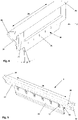
- FIGS. 2 and 3 now show a schematic representation of a top comb holder 1 according to the invention in a closed position ( figure 2 ) and in an open position ( figure 3 ).
- the top comb holder 1 has a fastening section 4 , a guide section 5 and a holding section 6 .
- the fastening section 4, the holding section 6 and the guide section 5 are shown as a single component.
- the fastening hole 18 is designed as a long hole in order to have a certain amount of leeway for an adjustment in the fastening.
- a guide slot 7 with a longitudinal axis 8 is provided in the guide section 5 . The guide slot 7 is closed towards the fastening section 4 at the bottom and is open in the other direction (upwards).
- An axis of rotation 14 is also provided in the guide section 5 .
- a clamping lever 13 is held on or on this axis of rotation 14 .
- the axis of rotation 14 is held in the clamping lever 13 and clipped into corresponding recesses in the guide section 5 . This makes it possible to remove the clamping lever 13 with the axis of rotation from the guide section 5 and thus from the top comb holder 1 in the event of a necessary replacement due to signs of wear or material fatigue.
- the clamping lever 13 In the closed position ( figure 2 ) the clamping lever 13 is connected to the guide section 5 via the axis of rotation 14 and to the holding section 6 via the locking coupling 15 . between the in figure 2 shown closed position and in figure 3 shown open position of the top comb holder 1, the difference is in the position of the clamping lever 13.
- the clamping lever 13 can be opened or closed with the movement 23.
- the locking coupling 15 engages.
- the locking coupling 15 consists of a locking element 16 attached to the holding section, for example a bolt, and a corresponding formation 17 in the clamping lever 13.
- the formation 17 is adapted to the locking element, so that in the engaged ( closed) state the latching element 16 is encompassed by the formation 17 in such a way that latching occurs.
- a lever 19 is formed on an end of the clamping lever facing away from the axis of rotation 14 . This lever 19 makes manual movement of the clamping lever into and out of the latched position easier.
- pressure elements 20, 21 and 22 are provided in the clamping lever 13 pressure elements 20, 21 and 22 are provided.
- the pressure elements 20, 21 and 22 are shown in the embodiment shown as cylindrical elements made of an elastic plastic.
- the pressure elements 20, 21 and 22 are each held in corresponding depressions 26 in the clamping lever 13.
- the depressions 26 are adapted to the geometric shape of the pressure elements 20, 21 and 22, so that the pressure elements 20, 21 and 22 are surrounded by the clamping lever 13 over more than 180 angular degrees. This means that the pressure elements 20, 21 and 22 cannot fall out of the corresponding depressions 26.
- a first pressure element 20 is positioned on the clamping lever 13 in such a way that it is directed against the open side of the guide slot 7 when the clamping lever 13 is in the closed position.
- the second pressure element 21 and the third pressure element 22 are positioned on the clamping lever 13 in such a way that, when the clamping lever 13 is in the closed position, they are directed against one longitudinal side of the guide slot 7 .
- the pressure elements 20, 21 and 23 produce the force components 24 and 25 which act accordingly on the top comb carrier 2 (see Fig figure 6 ).
- the clamping lever 13 can be held in a secured, closed position even without the use of a top comb carrier 2 .
- FIG 4 shows a schematic representation of a top comb carrier 2 according to the invention with a longitudinal extent 29.
- the top comb carrier 2 has a holder plate 27 and a stiffening element 28, the holder plate 27 and the stiffening element 28 extending over the entire longitudinal extent 29.
- a top comb attachment surface 30 is formed on the holder plate 27. In the illustration shown, the top comb attachment surface 30 is on the back of the holder plate 27. The top comb attachment surface 30 is inclined at the angle ⁇ relative to the holder plate 27.
- attachment holes 31 are provided for attaching a top comb set (not shown).
- a T-shaped area 32 is provided at the respective ends of the holder plate 27 seen in the longitudinal extent 29 .
- the T-shaped area 32 is formed onto the holder plate 27 . Via the longitudinal extension 29, one leg of the T-shape merges into the stiffening element 28 and the other two legs extend over the entire longitudinal extension 29.
- a T- or L-shaped area 32 is provided at the position of the top comb carrier 2 for fastening Top comb holder necessary, but the shape of the holder plate 27 between the areas 32 is not important for the attachment of the top comb carrier in the top comb holder.
- FIG. 5 shows a schematic representation of a top comb carrier 2 according to the invention with the top comb fitting 11 inserted.
- the top comb carrier 27 is shown from the opposite side.
- the top comb set 11 is held with the attachments 12 on the top comb attachment surface 30 on the holder plate 27 , the top comb attachment surface 30 being designed inclined relative to the holder plate 27 .
- the top comb fitting 11 is attached below the stiffening element 28 .
- a T-shaped portion 32 is provided at the respective ends of the holder plate 27, a T-shaped portion 32 is provided.
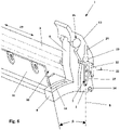
- FIG 6 shows a schematic representation of a top comb holder 1 according to the invention with an inserted top comb carrier 2 , with a top comb fitting on the top comb carrier 2 11 is attached to a top comb attachment surface 30 attached to the holder plate 27 .
- the top comb holder 1 has a fastening section 4 , a guide section 5 and a holding section 6 as well as a clamping lever 13 .
- a mounting hole 18 is provided in the mounting portion 4 .
- the guide section 5 has a guide slot 7 with a longitudinal axis 8 .
- the top comb attachment surface 30 is arranged at an angle ⁇ relative to the longitudinal axis 8 of the guide slot 7 .
- the top comb carrier 2 is introduced into the guide slot 7 with the T-shaped area 32 attached in its longitudinal extent 29 at the end of the holder plate 27 .
- the clamping lever 13 is brought into the closed position about the axis 14 and engaged in the latching coupling 15 .
- the first pressure element 20 located in the clamping lever 13 exerts pressure on the top comb carrier 2 with a force component 24 in the direction of the longitudinal axis 8 of the guide slot 7 and the top comb carrier 2 is pressed into the guide slot 7 .
- the additional second and third pressure elements 21 and 22 arranged in the clamping lever 13 is formed by the closing of the clamping lever 13, the force component 25 which pushes the top comb carrier 2 transversely to the longitudinal axis 8 in a defined position in the guide slot 7.
- the top comb carrier 2 can be extended out of the guide slot 7 in the direction of the longitudinal axis 8 and removed from the top comb holder 1 .
Landscapes
- Engineering & Computer Science (AREA)
- Textile Engineering (AREA)
- Preliminary Treatment Of Fibers (AREA)
Abstract
Die vorliegende Erfindung betrifft einen Fixkammhalter (1) zur Befestigung eines Fixkammträgers (2) in einer Kämmmaschine sowie einen Fixkammträger (2), wobei der Fixkammhalter (1) einen Befestigungsabschnitt (4) zur ortsfesten Anlage des Fixkammhalters (1) in der Kämmmaschine, einen Führungsabschnitt (5) mit einem Führungsschlitz (7) zur Aufnahme des Fixkammträgers (2), wobei der Führungsabschnitt (5) mit dem Befestigungsabschnitt (4) verbunden ist und der Führungsschlitz (7) eine Längsachse (8) aufweist, einen Halteabschnitt (6), wobei der Halteabschnitt (6) in gleicher Richtung wie die Längsachse (8) des Führungsschlitzes (7) vom Befestigungsabschnitt (4) wegweisend an diesem angeordnet ist, und einen Klemmhebel (13) aufweist, wobei der Klemmhebel (13) über eine Drehachse (14) mit dem Befestigungsabschnitt (4) und über den Führungsabschnitt (5) greifend mit dem Halteabschnitt (6) verbunden ist. Die Verbindung des Klemmhebels (13) mit dem Halteabschnitt (6) ist als eine Rastkupplung (15) ausgebildet und der Klemmhebel (13) weist zumindest zwei Druckelemente (20, 21, 22) zur Fixierung des Fixkammträgers (2) auf.The present invention relates to a top comb holder (1) for fastening a top comb holder (2) in a combing machine, and a top comb holder (2), the top comb holder (1) having a fastening section (4) for stationary positioning of the top comb holder (1) in the combing machine, a Guide section (5) with a guide slot (7) for receiving the top comb carrier (2), the guide section (5) being connected to the fastening section (4) and the guide slot (7) having a longitudinal axis (8), a holding section (6) , wherein the holding section (6) is arranged in the same direction as the longitudinal axis (8) of the guide slot (7) pointing away from the fastening section (4) on the latter, and has a clamping lever (13), the clamping lever (13) having an axis of rotation ( 14) is connected to the fastening section (4) and via the guide section (5) to the holding section (6). The connection of the clamping lever (13) to the holding section (6) is designed as a snap-in coupling (15) and the clamping lever (13) has at least two pressure elements (20, 21, 22) for fixing the top comb carrier (2).
Description
Die vorliegende Erfindung betrifft einen Fixkammhalter zur Befestigung eines Fixkammträgers in einer Kämmmaschine sowie einen Fixkammträger. Der Fixkammhalter weist einen Führungsabschnitt mit einem Führungsschlitz zur Aufnahme des Fixkammträgers, einen Befestigungsabschnitt zur ortsfesten Anlage des Fixkammhalters in der Kämmmaschine, einen Halteabschnitt und einen Klemmhebel auf, wobei der Klemmhebel über eine Drehachse mit dem Befestigungsabschnitt und über eine Rastkupplung mit dem Halteabschnitt verbunden ist.The present invention relates to a top comb holder for fastening a top comb carrier in a combing machine and a top comb carrier. The top comb holder has a guide section with a guide slot for accommodating the top comb carrier, a fastening section for stationary positioning of the top comb holder in the combing machine, a holding section and a clamping lever, the clamping lever being connected to the fastening section via a pivot axis and to the holding section via a snap-in coupling.
Der in einem Fixkammhalter eingesetzte Fixkammträger führt bei einer Kämmmaschine eine annähernd ellipsenförmige Bewegung durch und ist hierdurch und aufgrund seines Eingriffs in das auszukämmende Faserband sich ständig ändernden Beschleunigungskräften ausgesetzt. Dies führt insgesamt durch das Eigengewicht des Fixkammes zu einer hohen mechanischen Belastung der Verbindung und der Montageflächen des Fixkammträgers in der Aufnahme des Fixkammhalters. Diese Verbindungen sind derart gestaltet, dass der Fixkammhalter mit einer Aufnahme versehen ist in welche der Fixkamm eingesetzt und mittels einer Befestigungsvorrichtung fixiert ist. Die Befestigungsvorrichtung ist in Form einer federartigen Halteklammer aus Blech bewegbar an der Halterung angebracht. Im geschlossenen Zustand umgreift die Halteklammer aus Blech den Fixkamm und hält diesen in seiner Position gegenüber dem Fixkammhalter fest.The top comb carrier used in a top comb holder performs an approximately elliptical movement in a combing machine and is thereby exposed to constantly changing acceleration forces due to its engagement in the fiber sliver to be combed out. Overall, this leads to a high mechanical load on the connection and the mounting surfaces of the top comb carrier in the receptacle of the top comb holder due to the dead weight of the top comb. These connections are designed in such a way that the top comb holder is provided with a receptacle in which the top comb is inserted and fixed by means of a fastening device. The attachment device is movably attached to the bracket in the form of a spring-like sheet metal retaining clip. When closed, the sheet metal retaining clip grips the top comb and holds it in position relative to the top comb holder.
Die bekannten Fixkammträger sind in herkömmlicher Bauweise aus Aluminium hergestellt und weisen dementsprechend einen exakt masshaltigen Befestigungsbereich auf. Im Gegensatz dazu ist die Halteklammer aus Blech respektive Stahl aufgrund des Härtevorgangs nicht exakt masshaltig. Dies führt dazu, dass zwischen dem Befestigungsbereich des Fixkammträgers und der Halteklammer linienförmige Belastungen auftreten, die einen mechanischen Verschleiss im Befestigungsbereich des Fixkammträgers verursachen. Der mechanische Verschleiss aufgrund der linienförmigen Belastungen auf der Oberfläche des Befestigungsbereich des Fixkammträgers hat den Nachteil, dass die Halteklammer aus Blech den durch mechanischen Verschleiss veränderten Befestigungsbereich nicht mehr optimal umgreifen kann, wodurch sich der Fixkammträger aufgrund der ellipsenförmigen Bewegung mit Spiel in der Aufnahme des Fixkammhalters bewegen kann. Bedingt dadurch kann der Fixkamm nicht mehr die gewünschte Kämmleistung erbringen und die Kämmqualität nimmt unkontrollierbar ab. Ausserdem bewirkt die ellipsenförmige Bewegung des Fixkammträgers in der Aufnahme des Fixkammhalters, dass sich die Verbindung der Halteklammer am Fixkammhalter während des Betriebs der Kämmmaschine lockert und so die Halteklammer nur lose am Fixkammhalter befestigt ist, wodurch die gewünschte federwirkende Klemmkraft der Halteklammer zum Sichern des Fixkammträgers in der Aufnahme des Fixkammhalters erheblich verschlechtert wird.The known top comb carriers are made of aluminum in a conventional manner and accordingly have an exactly dimensionally stable fastening area. In contrast, the retaining clip made of sheet metal or steel is not exactly dimensionally accurate due to the hardening process. This leads to linear loads occurring between the attachment area of the top comb carrier and the retaining clip, which cause mechanical wear and tear in the attachment area of the top comb carrier. The mechanical wear due to the linear stresses on the surface of the attachment area of the top comb carrier has the disadvantage that the sheet metal retaining clip can no longer optimally encompass the attachment area changed by mechanical wear, whereby the Can move top comb carrier due to the elliptical movement with play in the recording of the top comb holder. As a result, the top comb can no longer provide the desired combing performance and the combing quality decreases uncontrollably. In addition, the elliptical movement of the top comb carrier in the seat of the top comb holder causes the connection of the retaining clip on the top comb holder to loosen during operation of the combing machine and the retaining clip is thus only loosely attached to the top comb holder, whereby the desired spring-acting clamping force of the retaining clip for securing the top comb carrier in the recording of the top comb holder is significantly worsened.
Ebenfalls nachteilig an der bekannten Konstruktion mit einer Halteklammer ist, dass die Halteklammer ohne den Einsatz eines Fixkammträgers nicht geschlossen werden kann weil ein Schliessen der Halteklammer ausschliesslich in Verbindung mit dem am Fixkammträger vorgesehenen Befestigungsbereichs möglich ist. Eine Einrichtung der Kämmmaschine erfolgt jedoch in vielen Fällen bei einem ausgebauten Fixkammträger. Wenn nun die Klammer geöffnet ist wird diese beim Einrichten der Kämmmaschine durch die Hin- und Her-Bewegung der Zange entsprechend lose mitbewegt. Dabei kann sich die Halteklammer in ihrer Befestigung am Fixkammhalter lockern, so dass beim späteren Schliessen der Halteklammer über den Befestigungsbereich des Fixkammträgers der Fixkammträger mit Spiel in der Aufnahme des Fixkammhalters gehalten wird.Another disadvantage of the known construction with a retaining clip is that the retaining clip cannot be closed without the use of a top comb carrier because the retaining clip can only be closed in connection with the fastening area provided on the top comb carrier. In many cases, however, the combing machine is set up when the top comb carrier has been removed. If the clamp is now open, it is loosely moved along with it when the combing machine is set up by the to-and-fro movement of the pliers. The retaining clip can loosen in its attachment to the top comb holder, so that when the retaining clip is later closed via the attachment area of the top comb carrier, the top comb carrier is held with play in the receptacle of the top comb holder.
Die
Es ist die Aufgabe der Erfindung einen Fixkammhalter und einen Fixkammträger zu schaffen, welche die Nachteile des Standes der Technik beheben und eine vom Einsatz eines Fixkammträgers unabhängige Verriegelung des Fixkammhalters zulassen.The object of the invention is to create a top comb holder and a top comb carrier which eliminate the disadvantages of the prior art and allow the top comb holder to be locked independently of the use of a top comb carrier.
Die Aufgabe wird gelöst durch die Merkmale der unabhängigen Ansprüche.The object is solved by the features of the independent claims.
Zur Lösung der Aufgabe wird ein Fixkammhalter zur Befestigung eines Fixkammträgers in einer Kämmmaschine vorgeschlagen mit einem Befestigungsabschnitt zur ortsfesten Anlage des Fixkammhalters in der Kämmmaschine, mit einem Führungsabschnitt mit einem Führungsschlitz zur Aufnahme des Fixkammträgers, wobei der Führungsabschnitt mit dem Befestigungsabschnitt verbunden ist und der Führungsschlitz eine Längsachse aufweist, mit einem Halteabschnitt, wobei der Halteabschnitt in gleicher Richtung wie die Längsachse des Führungsschlitzes vom Befestigungsabschnitt wegweisend an diesem angeordnet ist, und mit einem Klemmhebel, wobei der Klemmhebel über eine Drehachse mit dem Befestigungsabschnitt und über den Führungsabschnitt greifend mit dem Halteabschnitt verbunden ist. Die Verbindung des Klemmhebels mit dem Halteabschnitt ist als eine Rastkupplung ausgebildet und der Klemmhebel weist zumindest zwei Druckelemente zur Fixierung des Fixkammträgers auf.To solve the problem, a top comb holder for fastening a top comb carrier in a combing machine is proposed, with a fastening section for stationary contact of the top comb holder in the combing machine, with a guide section with a guide slot for receiving the top comb carrier, with the guide section being connected to the fastening section and the guide slot having a longitudinal axis, with a holding section, wherein the holding section is arranged on the fastening section pointing away from the fastening section in the same direction as the longitudinal axis of the guide slot, and with a clamping lever, the clamping lever being connected to the fastening section via a pivot axis and to the holding section, gripping over the guide section . The connection of the clamping lever to the holding section is designed as a snap-in coupling and the clamping lever has at least two pressure elements for fixing the top comb carrier.
Der vorgeschlagene Fixkammhalter besteht aus drei starr miteinander verbundenen Abschnitten, dem Befestigungsabschnitt, dem Halteabschnitt und dem Führungsabschnitt. Der Befestigungsabschnitt dient zur ortsfesten Verbindung des Fixkammhalters mit der Kämmmaschine. Dazu weist der Befestigungsabschnitt beispielsweise eine schlitzförmige Durchgangsöffnung für eine Schraube auf. Mit der Schraube wird der Fixkammhalter durch die Durchgangsöffnung mit einem Teil der Kämmmaschine verschraubt. Eine schlitzförmige Durchgangsöffnung hat den Vorteil, dass der Fixkammhalter in seiner Position in der Kämmmaschine entsprechend einer Grösse des Schlitzes eingestellt werden kann.The proposed top comb holder consists of three rigidly interconnected sections, the attachment section, the holding section and the guide section. The fastening section is used for the stationary connection of the top comb holder to the combing machine. For this purpose, the fastening section has, for example, a slit-shaped passage opening for a screw. With the screw, the top comb holder is screwed through the through-opening to a part of the combing machine. A slit-shaped passage opening has the advantage that the position of the top comb holder in the combing machine can be adjusted according to the size of the slit.
Der Führungsabschnitt weist einen Führungsschlitz auf und ist angrenzend an den Befestigungsabschnitt und/oder den Halteabschnitt vorgesehen. Der Führungsschlitz ist wegweisend vom Befestigungsabschnitt offen und gegen den Befestigungsabschnitt hin geschlossen ausgeführt. In den Führungsschlitz kann ein entsprechend ausgeformter Fixkammträger in Richtung der Längsachse des Führungsschlitzes gegen den Befestigungsabschnitt hin eingeführt werden. Dabei sind der Führungsschlitz und der Fixkammträger in ihren Dimensionen derart aufeinander abgestimmt, dass der Fixkammträger mit einem geringfügigen Spiel in den Führungsschlitz gleitet. Durch den unten geschlossenen Führungsschlitz ergibt sich automatisch die richtige Position des Fixkammträgers nach dessen Einführung in den Führungsschlitz. Eine spielfreie Halterung des Fixkammträgers im Führungsschlitz und damit im Fixkammhalter wird erst nach Schliessen des Klemmhebels erreicht.The guide section has a guide slot and is provided adjacent to the attachment section and/or the holding section. The guide slot is designed to be open, pointing away from the fastening section, and closed towards the fastening section. In the guide slot, a correspondingly shaped Top comb carriers are inserted in the direction of the longitudinal axis of the guide slot against the fastening section. The dimensions of the guide slot and the top comb carrier are matched to one another in such a way that the top comb carrier slides into the guide slot with a slight amount of play. The guide slot, which is closed at the bottom, automatically results in the correct position of the top comb carrier after it has been inserted into the guide slot. A play-free mounting of the top comb carrier in the guide slot and thus in the top comb holder is only achieved after closing the clamping lever.
Der Halteabschnitt ist an den Befestigungsabschnitt angrenzend vorgesehen und dient mit seinem vom Befestigungsabschnitt entfernten Ende der Bildung eines Teils der Rastkupplung für den Klemmhebel. Unter einer Rastkupplung ist ein aus zwei Teilen bestehendes zumindest teilweise ineinandergreifendes System zu verstehen. Dabei greift ein erstes Teil in ein weiteres entsprechend der Formgebung des ersten Teils angepasstes zweites Teil. Durch das Ineinandergreifen wird ein Einrasten bewirkt, dadurch, dass das Ineinandergreifen durch eine leichte Verformung des einen an der Rastkupplung beteiligten Teils während des Einrastvorgangs erreicht wird. Dadurch dass der Halteabschnitt in gleicher Richtung wie die Längsachse des Führungsschlitzes vom Befestigungsabschnitt wegweisend an diesem angeordnet ist, befindet sich die Rastkupplung oberhalb der offenen Ausgestaltung es Führungsschlitzes und der Fixkammträger wird an der Rastkupplung vorbei in den Führungsschlitz eingeführt.The holding section is provided adjacent to the fastening section and, with its end remote from the fastening section, serves to form part of the snap-in coupling for the clamping lever. A snap-in coupling is to be understood as meaning a system consisting of two parts, which at least partially engages in one another. A first part engages in another second part, which is adapted to the shape of the first part. The interlocking causes a snap-in, in that the interlocking is achieved by a slight deformation of the one part involved in the snap-in coupling during the snap-in process. Because the holding section is arranged in the same direction as the longitudinal axis of the guide slot pointing away from the fastening section, the locking coupling is located above the open configuration of the guide slot and the top comb carrier is inserted past the locking coupling into the guide slot.
Als weiterer Bestandteil des Fixkammhalters ist ein Klemmhebel vorgesehen. Der Klemmhebel ist über eine Drehachse mit dem Halteabschnitt respektive dem Befestigungsabschnitt verbunden. Dabei ist die Drehachse im Halteabschnitt gehalten und der Klemmhebel um die Drehachse schwenkbar an dieser gehalten. Als Drehachse kann beispielsweise ein Stahlstift auf welchem der Klemmhebel aufgeklipst ist vorgesehen sein. Es sind jedoch auch andere Arten von Drehachsen denkbar, beispielsweise im Halteabschnitt vorgesehene Noppen, welche in entsprechende Vertiefungen im Klemmhebel eingreifen und ebenfalls eine Schwenkbewegung des Klemmhebels um die Drehachse ermöglichen. An einem von der Drehachse abgewandten Ende des Klemmhebels ist der Klemmhebel derart ausgeformt, dass ein Einrasten um den als Rastkupplung ausgeführten Teil des Halteabschnitts erfolgt. Zur Einrastung des Klemmhebels am Halteabschnitt wird der Klemmhebel um die Drehachse gegen den Halteabschnitt verschwenkt bis der Klemmhebel am Halteabschnitt anschlägt. Durch eine Erhöhung der Kraft in Schwenkrichtung wird der Klemmhebel über den für die Rastkupplung vorgesehenen Teil des Halteabschnitts gehoben. Dadurch wird das Ende des Klemmhebels durch Übergreifen des Halteabschnittes in einer geschlossenen Stellung gehalten. Mit Hilfe des Einrastens ist der Klemmhebel zwischen der Drehachse und der Rastkupplung unter Spannung und ist aus der geschlossenen Stellung nur zu lösen durch eine Auflösung des Übergriffs über den Halteabschnitt. Dabei umgreift der Klemmhebel durch die Anordnung der Rastkupplung auch den sich im Führungsschlitz befindlichen Fixkammträger.A clamping lever is provided as a further component of the top comb holder. The clamping lever is connected to the holding section or the fastening section via a pivot. The axis of rotation is held in the holding section and the clamping lever is held on the axis of rotation so that it can swivel. A steel pin, for example, on which the clamping lever is clipped, can be provided as the axis of rotation. However, other types of axes of rotation are also conceivable, for example knobs provided in the holding section, which engage in corresponding depressions in the clamping lever and likewise enable a pivoting movement of the clamping lever about the axis of rotation. At one end of the clamping lever facing away from the axis of rotation, the clamping lever is shaped in such a way that it snaps into place around the Snap-in clutch running part of the holding section takes place. To engage the clamping lever on the holding section, the clamping lever is pivoted about the axis of rotation against the holding section until the clamping lever strikes the holding section. By increasing the force in the pivoting direction, the clamping lever is lifted above the part of the holding section provided for the snap-in coupling. As a result, the end of the clamping lever is held in a closed position by reaching over the holding section. With the help of the latching, the clamping lever between the axis of rotation and the snap-in coupling is under tension and can only be released from the closed position by dissolving the encroachment over the holding section. The clamping lever also grips the top comb carrier located in the guide slot due to the arrangement of the snap-in coupling.
Ein Vorteil dieser Konstruktion besteht darin, dass der Fixkammhalter geschlossen werden kann auch wenn kein Fixkammträger in den Führungsschlitz eingesetzt ist. Dies ermöglicht einen Probelauf der Kämmmaschine zu Revisions- und Einstellungszwecken ohne dass auf sich frei und unkontrolliert bewegende Bestandteile geachtet werden muss.An advantage of this construction is that the top comb holder can be closed even if no top comb carrier is inserted in the guide slot. This enables a test run of the combing machine for revision and adjustment purposes without having to pay attention to components that move freely and in an uncontrolled manner.
Weiter sind im Klemmhebel zumindest zwei Druckelemente vorgesehen. Durch die Druckelemente wird bei geschlossenem Klemmhebel der sich im Führungsschlitz befindliche Fixkammträger spielfrei gehalten. Die Druckelemente können dabei an den Klemmhebel angeformt sein oder sind zumindest im Klemmhebel gehalten. Als Druckelemente eignen sich insbesondere elastische Kunststoffelemente, wobei auch andere Ausführungen von Druckelementen, wie beispielsweise Federbleche, eingesetzt werden können. Dabei werden die Druckelemente beim Schliessen des Klemmhebels gegen eine Oberfläche des Fixkammträgers gedrückt und leicht gestaucht. Als alternative können die Druckelemente jedoch auch als Federn gestaltet sein, welche ebenfalls eine Haltekraft auf den Fixkammträger ausüben, wenn der Klemmhebel geschlossen ist. Die Druckelemente sind derart am Klemmhebel befestigt, dass sie sich bei einem verschwenken des Klemmhebels mit diesem bewegen. Beispielsweise können die Druckelemente an den Klemmhebel geschraubt oder mit diesem verklebt sein. Vorteilhafterweise sind die Druckelemente derart im Klemmhebel gehalten, dass sie ausgetauscht werden können, wenn sich über die Zeit eine Ermüdung deren Flexibilität und damit einhergehend eine Verringerung der zu erreichenden Klemmkraft ergibt.At least two pressure elements are also provided in the clamping lever. When the clamping lever is closed, the pressure elements hold the top comb carrier in the guide slot without play. The pressure elements can be formed onto the clamping lever or are at least held in the clamping lever. Elastic plastic elements are particularly suitable as pressure elements, although other types of pressure elements, such as spring plates, can also be used. When the clamping lever is closed, the pressure elements are pressed against a surface of the top comb carrier and slightly compressed. As an alternative, however, the pressure elements can also be designed as springs, which also exert a holding force on the top comb carrier when the clamping lever is closed. The pressure elements are fastened to the clamping lever in such a way that they move with the clamping lever when it is pivoted. For example, the pressure elements can be screwed to the clamping lever or glued to it. The pressure elements are advantageously held in the clamping lever in such a way that they can be exchanged can, if fatigue over time results in their flexibility and, as a result, a reduction in the clamping force to be achieved.
Vorteilhafterweise sind die Druckelemente derart im Klemmhebel angeordnet, dass durch sie verursachte Kraftkomponenten aus unterschiedlichen Richtungen gegen den Führungsschlitz gerichtet sind, wobei die Richtungen jeweils senkrecht zur Drehachse angeordnet sind. Wenn ein Fixkammträger im Führungsschlitz eingesetzt ist und der Klemmhebel geschlossen wird, drücken die Druckelemente auf Oberflächen des Fixkammträgers welche den Druckelementen gegenüber liegen, dadurch entstehen Kraftkomponenten. Der Klemmhebel wird unter Kraftaufwendung gegen den Halteabschnitt gedrückt und in die Rastkupplung eingerastet. Durch die Rastkupplung wird der Klemmhebel auch unter Spannung in seiner geschlossenen Position gehalten. Nur durch einen der Rastkupplung entgegenwirkenden Krafteinsatz kann die Rastkupplung gelöst und der Klemmhebel verschwenkt werden. Um den Fixkammträger im Führungsschlitz spielfrei festhalten zu können sind die durch die Druckelemente verursachten Kraftkomponenten aus unterschiedlichen Richtungen auf den Fixkammträger gerichtet. Durch die Ausrichtung der Kraftkomponenten senkrecht zur Drehachse wird vermieden, dass durch die Druckelemente Kräfte auf den Klemmhebel übertragen werden, welche zu einer Verschiebung des Klemmhebels auf der Drehachse führen könnten und zudem auch nicht für ein Festhalten des Fixkammträgers nutzbar wären.Advantageously, the pressure elements are arranged in the clamping lever in such a way that force components caused by them are directed against the guide slot from different directions, with the directions being arranged perpendicularly to the axis of rotation. When a top comb carrier is inserted in the guide slot and the clamping lever is closed, the pressure elements press on surfaces of the top comb carrier which are opposite the pressure elements, which results in force components. The clamping lever is pressed against the retaining section with the application of force and engaged in the snap-in coupling. The snap-in clutch keeps the clamping lever in its closed position even under tension. The locking coupling can only be released and the clamping lever pivoted by using force counteracting the locking coupling. In order to be able to hold the top comb carrier in the guide slot without play, the force components caused by the pressure elements are directed onto the top comb carrier from different directions. By aligning the force components perpendicular to the axis of rotation, it is avoided that forces are transmitted to the clamping lever by the pressure elements, which could lead to a displacement of the clamping lever on the axis of rotation and also could not be used to hold the top comb carrier.
Besonders bevorzugt sind die erste Kraftkomponente in Richtung der Längsachse des Führungsschlitzes und die zweite Kraftkomponente quer zur Längsachse des Führungsschlitzes und quer zur Drehachse angeordnet. Damit wird durch die erste Kraftkomponente erreicht, dass der eingesetzte Fixkammträger vollständig in den Führungsschlitz gleitet und auf dem geschlossenen Ende des Führungsschlitzes zur Anlage kommt. Die erste Kraftkomponente drückt in der Folge bei geschlossenem Klemmhebel über das Druckelement den Fixkammträger in Richtung der Längsachse des Führungsschlitzes in diesen hinein. Die zweite Kraftkomponenten wirkt derart, dass der Fixkammträger gegen die, dem Druckelement abgewandte, Seite des Führungsschlitzes gedrückt wird. Dadurch wird das für das Einführen des Fixkammträgers in den Führungsschlitz notwendige Spiel aufgehoben und der Fixkammträger in einer durch die Anlage des Führungsschlitzes im Fixkammhalter vorgegebenen Position fixiert.The first force component is particularly preferably arranged in the direction of the longitudinal axis of the guide slot and the second force component is arranged transversely to the longitudinal axis of the guide slot and transversely to the axis of rotation. The result of the first force component is that the top comb carrier used slides completely into the guide slot and comes to rest on the closed end of the guide slot. The first force component subsequently presses the top comb carrier into the guide slot in the direction of the longitudinal axis of the guide slot via the pressure element when the clamping lever is closed. The second force component acts in such a way that the top comb carrier is pressed against the side of the guide slot facing away from the pressure element. This makes it possible to insert the top comb carrier into the guide slot the necessary play is eliminated and the top comb carrier is fixed in a position specified by the system of the guide slot in the top comb holder.
Vorteilhafterweise ist zumindest eines der Druckelemente aus einem elektrisch leitfähigen Kunststoff hergestellt. Ein elektrisch leitfähiges Druckelement ermöglicht die Einrichtung einer Überwachung des Vorhandenseins eines Fixkammträgers im Fixkammhalter. Da der Fixkammhalter auch ohne eingesetzten Fixkammträger geschlossen werden kann, besteht die Möglichkeit die Kämmmaschine ohne Fixkamm zu betreiben. Um dies zu vermeiden respektive eine optische Kontrolle durch einen Bediener zu ergänzen, wird durch Schiessen des Klemmhebels bei einem eingesetzten Fixkammträger über das Druckelement ein elektrischer Kontakt hergestellt. Der elektronische Kontakt ist durch eine Steuerung der Kämmmaschine einfach zu überwachen. Besonders bevorzugt ist die zweite Kraftkomponente verursachende Druckelement mit aus einem elektrisch leitfähigen Kunststoff hergestellt ist. Bedingt dadurch, dass das zweite Druckelement den Fixkammträger gegen die Rückwand des Führungsschlitzes drückt ist für die Kontaktherstellung eine grössere Sicherheit gewährleistet.At least one of the pressure elements is advantageously made of an electrically conductive plastic. An electrically conductive pressure element enables monitoring of the presence of a top comb carrier in the top comb holder. Since the top comb holder can also be closed without the top comb carrier inserted, it is possible to operate the comber without a top comb. In order to avoid this or to supplement a visual check by an operator, an electrical contact is established via the pressure element by closing the clamping lever when a top comb carrier is inserted. The electronic contact can be easily monitored by a control of the combing machine. The pressure element causing the second force component is particularly preferably made from an electrically conductive plastic. Due to the fact that the second pressure element presses the top comb carrier against the rear wall of the guide slot, greater security is ensured for making contact.
In einer alternativen Ausführung zum elektrisch leitfähigen Druckelement ist am Klemmhebel ein Blechelement zur Durchleitung eines Messstromes vorgesehen. Das Blechelement kann beispielsweise aus einem auf den Klemmhebel aufgeschraubten Federblech bestehen. Durch eine leichte Verformung des Federblechs im geschlossenen Zustand des Fixkammhalters wird ein sicherer Kontakt zwischen dem Blechelement und dem Fixkammträger hergestellt. Damit wird die Funktion der Überwachung von der Funktion der Befestigung getrennt. Es steht dadurch eine breitere Auswahl an Werkstoffen für die Druckelemente zur Verfügung.In an alternative embodiment to the electrically conductive pressure element, a sheet metal element for conducting a measuring current is provided on the clamping lever. The sheet metal element can consist, for example, of a spring sheet metal screwed onto the clamping lever. A slight deformation of the spring plate when the top comb holder is closed ensures a secure contact between the sheet metal element and the top comb carrier. This separates the monitoring function from the fastening function. As a result, a wider selection of materials is available for the pressure elements.
Weiter ist es von Vorteil, wenn die Druckelemente zylinderförmig ausgebildet sind und jeweils in einer Vertiefung im Klemmhebel gehalten sind, wobei die Druckelemente von der jeweiligen Vertiefung um mehr als 180 Winkelgrade umschlossen sind. Dabei sind die zylinderförmigen Druckelemente mit ihrer Zylinderachse parallel zur Drehachse des Klemmhebels angeordnet. Die Druckelemente sind durch ein Einpressen in die dafür vorgesehenen Vertiefungen im Klemmhebel einfach zu montieren. Durch die Umschliessung um mehr als 180 Winkelgrade sind die Druckelemente in den Vertiefungen gefangen und können nicht herausfallen. Trotzdem ist bei Ermüdungs- oder Alterungserscheinungen eine einfache Auswechslung der Druckelemente möglich. Durch die parallele Anordnung der Druckelemente-Zylinder zur Drehachse wirkt das Druckelement auf den Fixträger beim Schliessen des Klemmhebels anfänglich auf einer Berührungslinie. Durch die Verformung des elastischen Druckelements beim Einrasten des Klemmhebels im Halteabschnitt entsteht ein flächiger Kontakt zwischen dem Fixkammträger und dem jeweiligen Druckelement, wodurch die jeweils wirkende Kraftkomponente optimal gegen eine Oberfläche des Fixkammträgers zur Wirkung kommt.It is also advantageous if the pressure elements are cylindrical and are each held in a recess in the clamping lever, with the pressure elements being enclosed by the respective recess by more than 180 angular degrees. The cylinder-shaped pressure elements are arranged with their cylinder axis parallel to the axis of rotation of the clamping lever. The pressure elements are easy to mount by pressing them into the recesses provided in the clamping lever. through the Enclosed by more than 180 degrees, the printing elements are trapped in the depressions and cannot fall out. Nevertheless, if there are signs of fatigue or aging, the printing elements can be easily replaced. Due to the parallel arrangement of the pressure element cylinders to the axis of rotation, the pressure element initially acts on the fixed support on a contact line when the clamping lever is closed. The deformation of the elastic pressure element when the clamping lever engages in the holding section creates a planar contact between the top comb carrier and the respective pressure element, as a result of which the force component acting in each case is optimally effective against a surface of the top comb carrier.
Bevorzugterweise ist die Drehachse lösbar im Fixkammhalter auf einer dem Halteabschnitt abgewandten Seite des Führungsschlitzes gehalten. Dabei ist die Drehachse vorteilhafterweise als Stift ausgeführt, welcher im Klemmhebel fixiert ist. Dadurch dass die Drehachse, respektive der Klemmhebel mit der Drehachse auf einer dem Halteabschnitt abgewandten Seite des Führungsschlitzes gehalten ist kann eine gezielte Krafteinwirkung der Druckelemente im Bereich des Führungsschlitzes erreicht werden. Die lösbare Befestigung der Drehachse ermöglicht einen Austausch des Klemmhebels, ohne den Fixkammhalter aus seiner eingestellten Position in der Kämmmaschine entfernen zu müssen.Preferably, the axis of rotation is releasably held in the top comb holder on a side of the guide slot facing away from the holding section. The axis of rotation is advantageously designed as a pin which is fixed in the clamping lever. Because the axis of rotation or the clamping lever is held with the axis of rotation on a side of the guide slot facing away from the holding section, a targeted application of force by the pressure elements in the area of the guide slot can be achieved. The detachable attachment of the rotary axis allows the clamping lever to be replaced without having to remove the top comb holder from its set position in the comber.
Vorteilhafterweise sind der Führungsabschnitt und der Befestigungsabschnitt und der Halteabschnitt einteilig ausgeformt. Eine einteilige Ausführung hat den Vorteil, dass keine Verbindungsstellen welche Toleranzen unterworfen sind entstehen. In dieser Ausführungsform kann das Bauteil beispielsweise als Spritzgussteil hergestellt werden. Durch die nicht notwendigen Verbindungsstellen steht auch eine vielfältigere Materialauswahl zu Verfügung. Das Bauteil kann beispielsweise aus Kunststoff oder Metall gefertigt sein.The guide section and the fastening section and the holding section are advantageously formed in one piece. A one-piece design has the advantage that there are no connection points that are subject to tolerances. In this embodiment, the component can be produced, for example, as an injection molded part. Due to the unnecessary connection points, a more diverse selection of materials is also available. The component can be made of plastic or metal, for example.
In einer bevorzugten Ausführung weist die Rastkupplung ein am Halteabschnitt angebrachtes und von diesem abstehenden Rastelement und eine im Klemmhebel angebrachte Ausformung auf, wobei die Ausformung in Ihrer Form mit dem Rastelement zumindest teilweise korrespondiert. Bei einem Schliessvorgang der Rastkupplung wird das Rastelement in der Ausformung aufgenommen. Zu einem eigentlichen Einrasten des Rastelements in der Ausformung führt beispielsweise eine Gestaltung der Ausformung dahingehend, dass das Rastelement beim Auftreffen auf die Ausformung einen Widerstand überwinden muss, um in die Ausformung aufgenommen zu werden. Dies kann durch die Schaffung einer Engstelle an der Ausformung oder einen Wulst am Rastelement erreicht werden. Eine Eigenheit aller Formen und Ausführungen von Rastkupplungen ist, dass ein Verlassen der eingerasteten Position nur durch eine Kraftaufwendung möglich ist.In a preferred embodiment, the snap-in coupling has a snap-in element attached to and protruding from the holding section and a protrusion made in the clamping lever, the shape of the protrusion at least partially corresponding to the snap-in element. In a closing process of the locking clutch the locking element was added to the molding. The latching element actually snaps into place in the formation, for example, if the formation is designed in such a way that the latching element has to overcome a resistance when it hits the formation in order to be accommodated in the formation. This can be achieved by creating a constriction on the molding or a bulge on the locking element. A peculiarity of all forms and designs of snap-in couplings is that it is only possible to leave the locked position by exerting force.
Besonders bevorzugt ist das Rastelement ein Bolzen und die Ausformung umfasst den Bolzen um mehr als 180 Winkelgrade. In dieser Ausführung ist die Ausformung im Klemmhebel eine auf den Bolzen abgestimmte kreisförmige Öffnung welche gegen den Bolzen gerichtet eine sektorale Öffnung von weniger als 180 Winkelgrade aufweist. Bei einer Bewegung des Klemmhebels gegen den Bolzen wird durch den Bolzen bei Auftreffen auf die Ausformung die Öffnung bei entsprechendem Kraftaufwand gespreizt, sodass der Bolzen in den kreisförmigen Teil der Ausformung gleiten kann. Sobald der Bolze mit seinem grössten Durchmesser die Öffnung passiert hat, wird die Spreizung durch die Elastizität des Materials rückgängig gemacht und der Bolzen ist in der Ausformung gehalten. Bevorzugterweise ist der Abstand zwischen der Drehachse und einem Zentrum des Bolzens kleiner als der Abstand zwischen der Drehachse und einem Zentrum der Ausformung im Klemmhebel. Damit kann eine spielfreie Halterung des Bolzens in der Ausformung und somit des Klemmhebels am Halteabschnitt erreicht werden. Eine Kraft welche benötigt wird um die Rastkupplung durch ein Ausschwenken des Klemmhebels zu lösen ist grösser als die auf die Druckelemente und damit auf den Klemmhebel wirkenden Kraftkomponenten.The latching element is particularly preferably a bolt and the formation surrounds the bolt by more than 180 angular degrees. In this embodiment, the formation in the clamping lever is a circular opening matched to the bolt, which has a sectoral opening of less than 180 degrees of angle directed towards the bolt. When the clamping lever is moved against the bolt, the bolt spreads the opening when it hits the formation with the appropriate force, so that the bolt can slide into the circular part of the formation. As soon as the bolt with its largest diameter has passed the opening, the expansion is reversed by the elasticity of the material and the bolt is held in the mold. The distance between the axis of rotation and a center of the bolt is preferably smaller than the distance between the axis of rotation and a center of the formation in the clamping lever. A play-free mounting of the bolt in the formation and thus of the clamping lever on the holding section can thus be achieved. A force which is required to release the locking coupling by pivoting the clamping lever is greater than the force components acting on the pressure elements and thus on the clamping lever.
Weiterhin vorgeschlagen wird ein Fixkammträger zur Befestigung in einem Fixkammhalter nach obiger Beschreibung. Der Fixkammträger hat eine Halterplatte und ein an der Halterplatte angebrachtes Versteifungselement, wobei die Halterplatte eine Längsausdehnung und eine Fixkammbefestigungsfläche aufweist. Die Halterplatte weist in Längsausdehnung gesehen zumindest an ihren beiden Enden jeweils einen T-förmigen oder L-förmigen Bereich auf. Das an der Halterplatte angebrachte Versteifungselement dient dazu die Halteplatte verwindungs- und biegesteifer zu machen. Die an der Halterplatte vorgesehene Fixkammbefestigungsfläche dient der Anlage eines Fixkammes. Dabei sind in heutigen Ausführungen in der Fixkammbefestigungsfläche Befestigungslöcher zur Verschraubung einer Fixkammgarnitur vorgesehen. Die Längsausdehnung der Halterplatte entspricht einer Breite einer herkömmlichen Kämmstelle in einer Kämmmaschine. Der T- oder L-förmige Bereich an den jeweiligen Enden des Fixkammträgers sind derart ausgestaltet, dass ein langer Schenkel und zumindest ein um einen rechten Winkel vom längeren Schenkel abstehender kurzer Schenkel vorhanden ist. Im Falle einer zu bevorzugenden T-förmigen Ausführung der Enden des Fixkammträgers ist der kurze Schenkel derart angeordnet, dass er zu beiden Seiten des langen Schenkels von diesem unter einem rechten Winkel wegweisend ist. Eine Dimensionierung der T- oder L-förmigen Enden des Fixkammträgers ist auf die Abmessungen des Führungsschlitzes des Fixkammhalters abgestimmt. Damit kann der Fixkammträger in den Führungsschlitz des Fixkammhalters eingefügt werden.Also proposed is a top comb carrier for attachment in a top comb holder as described above. The top comb carrier has a holder plate and a stiffening element attached to the holder plate, the holder plate having a longitudinal extent and a top comb attachment surface. Viewed in longitudinal extension, the holder plate has a T-shaped or L-shaped area at least at each of its two ends. The stiffening element attached to the holder plate serves to make the holding plate more torsion and bending resistant. The top comb attachment surface provided on the holder plate serves to attach a top comb. In today's designs, fastening holes for screwing on a top comb set are provided in the top comb fastening surface. The longitudinal extent of the holder plate corresponds to a width of a conventional combing point in a combing machine. The T-shaped or L-shaped area at the respective ends of the top comb carrier are designed in such a way that there is a long leg and at least one short leg protruding at a right angle from the longer leg. In the case of a preferred T-shaped design of the ends of the top comb support, the short leg is arranged in such a way that it points away from the long leg at a right angle on both sides of the latter. A dimensioning of the T- or L-shaped ends of the top comb carrier is matched to the dimensions of the guide slot of the top comb holder. This allows the top comb carrier to be inserted into the guide slot of the top comb holder.
In einem eingebauten Zustand wirken die beiden durch die Druckelemente im Klemmhebel verursachten Kraftkomponenten auf die beiden Schenkel der T- oder L-förmigen Enden der Halterplatte. Die im Klemmhebel angeordneten Druckelemente pressen den Fixkammträger in eine definierte Position im Führungsschlitz des Fixkammhalters. Die auf den Fixkammhalter wirkenden Kraftkomponenten bilden dabei nicht gleichzeitig die Sicherung der Halterung wie dies in den ursprünglichen Konstruktionen mit den Halteklammern der Fall war. Die Sicherung der Halterung wird durch die Rastkupplung zwischen dem Klemmhebel und dem Halteabschnitt erreicht und wird nicht in die eigentliche Befestigung des Fixkammträgers integriert.When installed, the two force components caused by the pressure elements in the clamping lever act on the two legs of the T-shaped or L-shaped ends of the holder plate. The pressure elements arranged in the clamping lever press the top comb carrier into a defined position in the guide slot of the top comb holder. The force components acting on the top comb holder do not simultaneously secure the holder as was the case in the original designs with the retaining clips. The holder is secured by the locking coupling between the clamping lever and the holding section and is not integrated into the actual fastening of the top comb carrier.
Bevorzugterweise ist die Fixkammbefestigungsfläche gegenüber der Halterplatte um 5 bis 20 Winkelgrade geneigt. Im eingebauten Zustand entspricht eine Ausrichtung der Halterplatte einer Anordnung der langen Schenkel der Enden des Fixkammträgers, wodurch die Ausrichtung der Halterplatte der Längsachse des Führungsschlitzes des Fixkammhalters entspricht. Bei einem Ein- oder Ausbauvorgang des Fixkammträgers in oder aus dem Fixkammhalter wird der Fixkammträger in Richtung der Längsachse des Führungsschlitzes des Fixkammhalters bewegt. Aufgrund der Neigung der Fixkammbefestigungsfläche wird der Fixkammträger nicht in der Ausrichtung der Fixkammgarnitur, sondern abweichend davon bewegt. Dadurch kann ein Einführen oder Ausfahren des Fixkammträgers in den Fixkammhalter in einer zur Fixkammbefestigungsfläche geneigten Ebene erfolgen. Die beengten Platzverhältnisse im Bereich der Fixkammgarnitur einer Kämmmaschine können besser ausgenutzt werden. Es wird bei einer entsprechenden Neigung auch erreicht, dass Fixkammträger unabhängig von einer Stellung des Kämmaggregates aus dem Fixkammhalter ausgebaut werden kann.The top comb attachment surface is preferably inclined by 5 to 20 degrees relative to the holder plate. In the installed state, an orientation of the holder plate corresponds to an arrangement of the long legs of the ends of the top comb carrier, as a result of which the orientation of the holder plate corresponds to the longitudinal axis of the guide slot of the top comb holder. When installing or removing the top comb carrier in or out of the top comb holder, the top comb carrier is moved in the direction of the longitudinal axis of the guide slot of the top comb holder. Because of the tendency of top comb mounting surface, the top comb carrier is not moved in the alignment of the top comb set, but deviates from it. As a result, the top comb carrier can be inserted or extended into the top comb holder in a plane inclined to the top comb attachment surface. The cramped space conditions in the top comb clothing area of a comber can be better utilized. With a corresponding inclination, it is also achieved that the top comb carrier can be removed from the top comb holder independently of a position of the combing unit.
Vorteilhafterweise ist der Fixkammträger mit einer elektrisch-leitfähigen Beschichtung, vorzugsweise einer chemisch vernickelten Beschichtung, zumindest teilweise überzogen. Die Beschichtung erleichtert die Aufrechterhaltung eines Kontaktes des elektrisch leitfähigen Druckelements mit der Oberfläche der Halterplatte. Sobald ein Fixkammträger in den Fixkammhalter eingefügt ist und der Klemmhebel des Fixkammhalters geschlossen ist, kann dies elektrisch festgestellt werden. Dadurch kann verhindert werden, dass das Kämmaggregat in Betrieb genommen wird, wenn kein Fixkammträger eingesetzt ist.Advantageously, the top comb carrier is at least partially covered with an electrically conductive coating, preferably a chemically nickel-plated coating. The coating facilitates maintaining contact of the electrically conductive printing element with the surface of the holder plate. As soon as a top comb carrier is inserted into the top comb holder and the clamping lever of the top comb holder is closed, this can be detected electrically. This can prevent the combing unit from being put into operation when no top comb carrier is used.
Weiter wird Verfahren vorgeschlagen zur Befestigung und Überwachung eines Fixkammträgers in einer Kämmmaschine, mit einem Fixkammhalter und einem Fixkammträger, wobei der Fixkammhalter einen Führungsabschnitt mit einem Führungsschlitz zur Aufnahme des Fixkammes und einen Befestigungsabschnitt zur ortsfesten Anlage des Fixkammhalters in der Kämmmaschine und einen Halteabschnitt und einen Klemmhebel aufweist, wobei der Klemmhebel über den Führungsabschnitt greifend mit dem Halteabschnitt mit einer eine Rastkupplung verbunden ist, und mit einem Fixkammträger mit einer Längsausdehnung, wobei der Fixkammträger in Längsausdehnung gesehen an seinen beiden Enden jeweils einen T-förmigen oder L-förmigen Bereich aufweist. Im Klemmhebel sind zumindest zwei Druckelemente vorgesehen. Der Fixkammträger wird in den Führungsschlitz des Führungsabschnitts eingeführt und der Klemmhebel wird über die Rastkupplung mit dem Halteabschnitt zum Einrasten gebracht, wobei durch die Einrastbewegung die Druckelemente gegen den T-förmigen oder L-förmigen Bereich des Fixkammträgers gepresst werden.A method is also proposed for fastening and monitoring a top comb carrier in a combing machine, with a top comb holder and a top comb carrier, the top comb holder having a guide section with a guide slot for receiving the top comb and a fastening section for stationary installation of the top comb holder in the combing machine and a holding section and a clamping lever wherein the clamping lever is connected via the guide section to the holding section with a snap-in coupling, and with a top comb carrier with a longitudinal extent, the top comb carrier having a T-shaped or L-shaped area at each of its two ends when viewed in the longitudinal extent. At least two pressure elements are provided in the clamping lever. The top comb carrier is inserted into the guide slot of the guide section and the clamping lever is snapped into place with the holding section via the snap-in coupling, the pressure elements being pressed against the T-shaped or L-shaped area of the top comb carrier by the snap-in movement.
Vorteilhafterweise wird bei eingerastetem Klemmhebel eine elektrisch leitende Verbindung zwischen dem Fixkammträger und dem Fixkammhalter hergestellt. Über diese geschlossene elektrische Verbindung ist eine Überwachung des Vorhandenseins eines Fixkammträgers im Fixkammhalter möglich. Durch die Überwachung kann verhindert werden, dass ein Kämmbetrieb gestartet wird, ohne dass ein Fixkammträger und damit eine Fixkammgarnitur eingesetzt sind. Auch ist ein Betrieb bei einem nicht korrekt geschlossenen Klemmhebel nicht möglich.Advantageously, when the clamping lever is engaged, an electrically conductive connection is established between the top comb carrier and the top comb holder. This closed electrical connection allows monitoring of the presence of a top comb carrier in the top comb holder. Monitoring can prevent a combing operation from being started without a top comb carrier and thus a top comb set being used. Operation is also not possible if the clamping lever is not correctly closed.
Im Folgenden wird die Erfindung anhand beispielhafter Ausführungsformen erklärt und durch Zeichnungen näher erläutert. Es zeigen
Figur 1- eine schematische Darstellung einer Fixkammbefestigung nach dem Stand der Technik;
Figur 2- eine schematische Darstellung eines erfindungsgemässen Fixkammhalters in einer geschlossenen Stellung;
Figur 3- eine schematische Darstellung eines erfindungsgemässen Fixkammhalters in einer offenen Stellung;
Figur 4- eine schematische Darstellung eines erfindungsgemässen Fixkammträgers;
Figur 5- eine schematische Darstellung eines erfindungsgemässen Fixkammträgers mit eingesetzter Fixkammgarnitur und
Figur 6- eine schematische Darstellung eines erfindungsgemässen Fixkammhalters mit eingesetztem Fixkammträger.
- figure 1
- a schematic representation of a top comb attachment according to the prior art;
- figure 2
- a schematic representation of an inventive top comb holder in a closed position;
- figure 3
- a schematic representation of an inventive top comb holder in an open position;
- figure 4
- a schematic representation of a top comb carrier according to the invention;
- figure 5
- a schematic representation of a top comb carrier according to the invention with a top comb set and
- figure 6
- a schematic representation of a top comb holder according to the invention with an inserted top comb carrier.
Die
Weiter ist im Führungsabschnitt 5 eine Drehachse 14 vorgesehen. An oder auf dieser Drehachse 14 ist ein Klemmhebel 13 gehalten. Im gezeigten Ausführungsbeispiel ist die Drehachse 14 im Klemmhebel 13 gehalten und in entsprechende Aussparungen im Führungsabschnitt 5 eingeclipst. Dies ermöglicht den Klemmhebel 13 mit der Drehachse vom Führungsabschnitt 5 und damit vom Fixkammhalter 1 zu entfernen bei einem notwendigen Austausch aufgrund von Verschleisserscheinungen oder Materialermüdung.An axis of
In der geschlossenen Stellung (
Im Klemmhebel 13 sind Druckelemente 20, 21 und 22 vorgesehen. Die Druckelemente 20, 21 und 22 sind in der gezeigten Ausführungsform als zylindrische aus einem elastischen Kunststoff hergestellte Elemente dargestellt. Die Druckelemente 20, 21 und 22 sind jeweils in entsprechenden Vertiefungen 26 im Klemmhebel 13 gehalten. Die Vertiefungen 26 sind an die geometrische Formgebung der Druckelemente 20, 21 und 22 angepasst, sodass die Druckelemente 20, 21 und 22 vom Klemmhebel 13 über mehr als 180 Winkelgrade umfasst werden. Damit ist ein Herausfallen der Druckelemente 20, 21 und 22 aus den entsprechenden Vertiefungen 26 nicht möglich. Ein erstes Druckelement 20 ist derart am Klemmhebel 13 positioniert, dass es in der geschlossenen Stellung des Klemmhebels 13 gegen die offene Seite des Führungsschlitzes 7 gerichtet ist. Das zweite Druckelement 21 und das dritte Druckelement 22 sind derart am Klemmhebel 13 positioniert, dass sie in der geschlossenen Stellung des Klemmhebels 13 gegen die eine Längsseite des Führungsschlitzes 7 gerichtet sind. Bei einem geschlossenen Klemmhebel 13 und einem eingesetzten Fixkammträger 2 ergeben sich durch die Druckelemente 20, 21 und 23 die Kraftkomponenten 24 und 25 welche entsprechend auf den Fixkammträger 2 wirken (siehe
Die vorliegende Erfindung ist nicht auf die dargestellten und beschriebenen Ausführungsbeispiele beschränkt. Abwandlungen im Rahmen der Patentansprüche sind ebenso möglich wie eine Kombination der Merkmale, auch wenn diese in unterschiedlichen Ausführungsbeispielen dargestellt und beschrieben sind.The present invention is not limited to the illustrated and described embodiments. Modifications within the scope of the patent claims are just as possible as a combination of the features, even if they are shown and described in different exemplary embodiments.
- 11
- Fixkammhaltertop comb holder
- 22
- Fixkammträgertop comb carrier
- 33
- Halteklammerretaining clip
- 44
- Befestigungsabschnitt FixkammhalterFastening section top comb holder
- 55
- Führungsabschnitt FixkammhalterTop comb holder guide section
- 66
- Halteabschnitt FixkammhalterHolding section top comb holder
- 77
- Führungsschlitzguide slot
- 88th
- Längsachse FührungsschlitzLongitudinal guide slot
- 99
- Achse HalteklammerAxle retaining clip
- 1010
- Befestigungsbereich FixkammträgerFastening area for top comb carrier
- 1111
- Fixkammgarniturtop comb set
- 1212
- Befestigung FixkammgarniturFastening top comb set
- 1313
- Klemmhebelclamping lever
- 1414
- Drehachseaxis of rotation
- 1515
- Rastkupplungsnap-in clutch
- 1616
- Rastelementlocking element
- 1717
- Ausformungmolding
- 1818
- Befestigungslochmounting hole
- 1919
- Hebellever
- 2020
- Erstes DruckelementFirst pressure element
- 2121
- Zweites DruckelementSecond pressure element
- 2222
- Drittes DruckelementThird pressure element
- 2323
- Bewegung Klemmhebelmovement of the clamping lever
- 2424
- Erste Kraftkomponente DruckelementFirst force component pressure element
- 2525
- Zweite Kraftkomponente DruckelementSecond force component pressure element
- 2626
- Vertiefungdeepening
- 2727
- Halterplatteholder plate
- 2828
- Versteifungselementstiffening element
- 2929
- Längsausdehnunglongitudinal expansion
- 3030
- FixkammbefestigungsflächeTop comb mounting surface
- 3131
- Befestigungslochmounting hole
- 3232
- T-förmiger BereichT-shaped area
- ββ
- Winkelangle
Claims (15)
die Verbindung des Klemmhebels (13) mit dem Halteabschnitt (6) als eine Rastkupplung (15) ausgebildet ist und der Klemmhebel (13) zumindest zwei Druckelemente (20, 21, 22) zur Fixierung des Fixkammträgers (2) aufweist.Top comb holder (1) for fastening a top comb carrier (2) in a combing machine
the connection of the clamping lever (13) to the holding section (6) is designed as a snap-in coupling (15) and the clamping lever (13) has at least two pressure elements (20, 21, 22) for fixing the top comb carrier (2).
Applications Claiming Priority (1)
| Application Number | Priority Date | Filing Date | Title |
|---|---|---|---|
| CH00294/21A CH718461A1 (en) | 2021-03-19 | 2021-03-19 | Holder for a top comb of a combing machine. |
Publications (1)
| Publication Number | Publication Date |
|---|---|
| EP4060102A1 true EP4060102A1 (en) | 2022-09-21 |
Family
ID=80682683
Family Applications (1)
| Application Number | Title | Priority Date | Filing Date |
|---|---|---|---|
| EP22156498.2A Pending EP4060102A1 (en) | 2021-03-19 | 2022-02-14 | Holder for a top comb of a combing machine |
Country Status (2)
| Country | Link |
|---|---|
| EP (1) | EP4060102A1 (en) |
| CH (1) | CH718461A1 (en) |
Cited By (1)
| Publication number | Priority date | Publication date | Assignee | Title |
|---|---|---|---|---|
| CN116876121A (en) * | 2023-08-14 | 2023-10-13 | 上海敦孚精梳机械有限公司 | A top comb clamping device and top comb position adjustment method for combing machines |
Citations (6)
| Publication number | Priority date | Publication date | Assignee | Title |
|---|---|---|---|---|
| DE10252098A1 (en) | 2002-11-08 | 2004-05-27 | Staedtler + Uhl Kg | Top comb mounting, for a textile combing machine, has a plastics insert as a coating between the comb and the holder to reduce wear, or the holder section is wholly of plastics |
| EP2085505A2 (en) * | 2008-01-29 | 2009-08-05 | Maschinenfabrik Rieter Ag | Fixing comb of a comb machine |
| CN202099443U (en) * | 2011-06-10 | 2012-01-04 | 浙江锦峰纺织机械有限公司 | Top comb |
| CH707012A2 (en) | 2012-09-28 | 2014-03-31 | Rieter Ag Maschf | A top comb for a combing machine. |
| CN204039572U (en) * | 2013-07-25 | 2014-12-24 | 拉克施米机械制造有限公司 | For the stop device of the top comb locking in comb |
| CN105420859A (en) * | 2016-01-13 | 2016-03-23 | 江苏凯宫机械股份有限公司 | Compression spring for top comb plates of intelligent combing machine |
Family Cites Families (3)
| Publication number | Priority date | Publication date | Assignee | Title |
|---|---|---|---|---|
| CN2094556U (en) * | 1991-06-29 | 1992-01-29 | 温州市锦峰纺织机械配件厂 | Top comb |
| CN201593083U (en) * | 2009-11-19 | 2010-09-29 | 浙江锦峰纺织机械有限公司 | Novel inlaid integrated top comb |
| CH716075A1 (en) * | 2019-04-15 | 2020-10-15 | Graf Cie Ag | Fixed comb holder for a combing machine. |
-
2021
- 2021-03-19 CH CH00294/21A patent/CH718461A1/en not_active Application Discontinuation
-
2022
- 2022-02-14 EP EP22156498.2A patent/EP4060102A1/en active Pending
Patent Citations (6)
| Publication number | Priority date | Publication date | Assignee | Title |
|---|---|---|---|---|
| DE10252098A1 (en) | 2002-11-08 | 2004-05-27 | Staedtler + Uhl Kg | Top comb mounting, for a textile combing machine, has a plastics insert as a coating between the comb and the holder to reduce wear, or the holder section is wholly of plastics |
| EP2085505A2 (en) * | 2008-01-29 | 2009-08-05 | Maschinenfabrik Rieter Ag | Fixing comb of a comb machine |
| CN202099443U (en) * | 2011-06-10 | 2012-01-04 | 浙江锦峰纺织机械有限公司 | Top comb |
| CH707012A2 (en) | 2012-09-28 | 2014-03-31 | Rieter Ag Maschf | A top comb for a combing machine. |
| CN204039572U (en) * | 2013-07-25 | 2014-12-24 | 拉克施米机械制造有限公司 | For the stop device of the top comb locking in comb |
| CN105420859A (en) * | 2016-01-13 | 2016-03-23 | 江苏凯宫机械股份有限公司 | Compression spring for top comb plates of intelligent combing machine |
Cited By (1)
| Publication number | Priority date | Publication date | Assignee | Title |
|---|---|---|---|---|
| CN116876121A (en) * | 2023-08-14 | 2023-10-13 | 上海敦孚精梳机械有限公司 | A top comb clamping device and top comb position adjustment method for combing machines |
Also Published As
| Publication number | Publication date |
|---|---|
| CH718461A1 (en) | 2022-09-30 |
| CN115110179A (en) | 2022-09-27 |
Similar Documents
| Publication | Publication Date | Title |
|---|---|---|
| EP2200134B1 (en) | Component with casing for profile rail | |
| EP3895259B1 (en) | Brush module and assembly method | |
| EP3387720B1 (en) | Side-by-side component | |
| DE202007008610U1 (en) | fastening system | |
| WO2008138613A1 (en) | Locking clip for plug connector housings | |
| EP3621483B1 (en) | Retaining device for a front panel of a drawer | |
| EP1856417B1 (en) | Heavy-duty mounting for connecting two components | |
| DE4317564C2 (en) | Door opener with a lockable, swiveling latch | |
| AT519906B1 (en) | furniture hinge | |
| EP3621484B1 (en) | Holding device for a front panel of a drawer | |
| DE3110298C2 (en) | ||
| EP2033266B1 (en) | Cable connection clamp | |
| EP2570541B1 (en) | Actuating tool bar | |
| EP4060102A1 (en) | Holder for a top comb of a combing machine | |
| EP4097802B1 (en) | Retaining frame for a plug connector, method, plug connector and electronic device | |
| DE202016103609U1 (en) | Adapter for mounting on a fixed point of a vehicle | |
| EP2046593B1 (en) | Door module with window regulator device | |
| EP1645467B1 (en) | Fastening device for a lamp and assembly process | |
| DE102012109056A1 (en) | Arrangement for mounting and/or dismounting of component for use in labeling machines for labeling e.g. bottles, has lever that is provided to engage latching lugs with bolts of component and to remove component from fastening element | |
| EP2578891B1 (en) | Adapter | |
| DE19844095C1 (en) | Connecting strip for telecommunications technology | |
| EP0673085A2 (en) | Device for locking a connector housing | |
| EP4438839B1 (en) | Clamping unit for fixing a fitting part in a fitting groove of a window or a door | |
| DE102021114670B4 (en) | Ferrule with improved positioning structure for the fixed end of the ferrule | |
| EP4446541A1 (en) | Lid fitting and furniture with such a lid fitting |
Legal Events
| Date | Code | Title | Description |
|---|---|---|---|
| PUAI | Public reference made under article 153(3) epc to a published international application that has entered the european phase |
Free format text: ORIGINAL CODE: 0009012 |
|
| STAA | Information on the status of an ep patent application or granted ep patent |
Free format text: STATUS: THE APPLICATION HAS BEEN PUBLISHED |
|
| AK | Designated contracting states |
Kind code of ref document: A1 Designated state(s): AL AT BE BG CH CY CZ DE DK EE ES FI FR GB GR HR HU IE IS IT LI LT LU LV MC MK MT NL NO PL PT RO RS SE SI SK SM TR |
|
| STAA | Information on the status of an ep patent application or granted ep patent |
Free format text: STATUS: REQUEST FOR EXAMINATION WAS MADE |
|
| 17P | Request for examination filed |
Effective date: 20230321 |
|
| RBV | Designated contracting states (corrected) |
Designated state(s): AL AT BE BG CH CY CZ DE DK EE ES FI FR GB GR HR HU IE IS IT LI LT LU LV MC MK MT NL NO PL PT RO RS SE SI SK SM TR |
|
| P01 | Opt-out of the competence of the unified patent court (upc) registered |
Effective date: 20230519 |
|
| STAA | Information on the status of an ep patent application or granted ep patent |
Free format text: STATUS: EXAMINATION IS IN PROGRESS |
|
| RAP3 | Party data changed (applicant data changed or rights of an application transferred) |
Owner name: RIETER AG |
|
| 17Q | First examination report despatched |
Effective date: 20240816 |