EP4060140B1 - Kernelement und verfahren zu seiner herstellung - Google Patents
Kernelement und verfahren zu seiner herstellung Download PDFInfo
- Publication number
- EP4060140B1 EP4060140B1 EP20887381.0A EP20887381A EP4060140B1 EP 4060140 B1 EP4060140 B1 EP 4060140B1 EP 20887381 A EP20887381 A EP 20887381A EP 4060140 B1 EP4060140 B1 EP 4060140B1
- Authority
- EP
- European Patent Office
- Prior art keywords
- flat plate
- notches
- core member
- plate members
- rectangular shape
- Prior art date
- Legal status (The legal status is an assumption and is not a legal conclusion. Google has not performed a legal analysis and makes no representation as to the accuracy of the status listed.)
- Active
Links
Images


Classifications
-
- B—PERFORMING OPERATIONS; TRANSPORTING
- B32—LAYERED PRODUCTS
- B32B—LAYERED PRODUCTS, i.e. PRODUCTS BUILT-UP OF STRATA OF FLAT OR NON-FLAT, e.g. CELLULAR OR HONEYCOMB, FORM
- B32B3/00—Layered products comprising a layer with external or internal discontinuities or unevennesses, or a layer of non-planar shape; Layered products comprising a layer having particular features of form
- B32B3/10—Layered products comprising a layer with external or internal discontinuities or unevennesses, or a layer of non-planar shape; Layered products comprising a layer having particular features of form characterised by a discontinuous layer, i.e. formed of separate pieces of material
- B32B3/12—Layered products comprising a layer with external or internal discontinuities or unevennesses, or a layer of non-planar shape; Layered products comprising a layer having particular features of form characterised by a discontinuous layer, i.e. formed of separate pieces of material characterised by a layer of regularly- arranged cells, e.g. a honeycomb structure
-
- B—PERFORMING OPERATIONS; TRANSPORTING
- B29—WORKING OF PLASTICS; WORKING OF SUBSTANCES IN A PLASTIC STATE IN GENERAL
- B29D—PRODUCING PARTICULAR ARTICLES FROM PLASTICS OR FROM SUBSTANCES IN A PLASTIC STATE
- B29D24/00—Producing articles with hollow walls
- B29D24/002—Producing articles with hollow walls formed with structures, e.g. cores placed between two plates or sheets, e.g. partially filled
- B29D24/005—Producing articles with hollow walls formed with structures, e.g. cores placed between two plates or sheets, e.g. partially filled the structure having joined ribs, e.g. honeycomb
-
- B—PERFORMING OPERATIONS; TRANSPORTING
- B29—WORKING OF PLASTICS; WORKING OF SUBSTANCES IN A PLASTIC STATE IN GENERAL
- B29D—PRODUCING PARTICULAR ARTICLES FROM PLASTICS OR FROM SUBSTANCES IN A PLASTIC STATE
- B29D99/00—Subject matter not provided for in other groups of this subclass
- B29D99/0089—Producing honeycomb structures
-
- B—PERFORMING OPERATIONS; TRANSPORTING
- B32—LAYERED PRODUCTS
- B32B—LAYERED PRODUCTS, i.e. PRODUCTS BUILT-UP OF STRATA OF FLAT OR NON-FLAT, e.g. CELLULAR OR HONEYCOMB, FORM
- B32B27/00—Layered products comprising a layer of synthetic resin
- B32B27/18—Layered products comprising a layer of synthetic resin characterised by the use of special additives
- B32B27/20—Layered products comprising a layer of synthetic resin characterised by the use of special additives using fillers, pigments, thixotroping agents
-
- B—PERFORMING OPERATIONS; TRANSPORTING
- B32—LAYERED PRODUCTS
- B32B—LAYERED PRODUCTS, i.e. PRODUCTS BUILT-UP OF STRATA OF FLAT OR NON-FLAT, e.g. CELLULAR OR HONEYCOMB, FORM
- B32B3/00—Layered products comprising a layer with external or internal discontinuities or unevennesses, or a layer of non-planar shape; Layered products comprising a layer having particular features of form
- B32B3/02—Layered products comprising a layer with external or internal discontinuities or unevennesses, or a layer of non-planar shape; Layered products comprising a layer having particular features of form characterised by features of form at particular places, e.g. in edge regions
- B32B3/06—Layered products comprising a layer with external or internal discontinuities or unevennesses, or a layer of non-planar shape; Layered products comprising a layer having particular features of form characterised by features of form at particular places, e.g. in edge regions for securing layers together; for attaching the product to another member, e.g. to a support, or to another product, e.g. groove/tongue, interlocking
-
- B—PERFORMING OPERATIONS; TRANSPORTING
- B32—LAYERED PRODUCTS
- B32B—LAYERED PRODUCTS, i.e. PRODUCTS BUILT-UP OF STRATA OF FLAT OR NON-FLAT, e.g. CELLULAR OR HONEYCOMB, FORM
- B32B37/00—Methods or apparatus for laminating, e.g. by curing or by ultrasonic bonding
- B32B37/14—Methods or apparatus for laminating, e.g. by curing or by ultrasonic bonding characterised by the properties of the layers
- B32B37/146—Methods or apparatus for laminating, e.g. by curing or by ultrasonic bonding characterised by the properties of the layers whereby one or more of the layers is a honeycomb structure
-
- B—PERFORMING OPERATIONS; TRANSPORTING
- B32—LAYERED PRODUCTS
- B32B—LAYERED PRODUCTS, i.e. PRODUCTS BUILT-UP OF STRATA OF FLAT OR NON-FLAT, e.g. CELLULAR OR HONEYCOMB, FORM
- B32B5/00—Layered products characterised by the non- homogeneity or physical structure, i.e. comprising a fibrous, filamentary, particulate or foam layer; Layered products characterised by having a layer differing constitutionally or physically in different parts
- B32B5/02—Layered products characterised by the non- homogeneity or physical structure, i.e. comprising a fibrous, filamentary, particulate or foam layer; Layered products characterised by having a layer differing constitutionally or physically in different parts characterised by structural features of a fibrous or filamentary layer
-
- B—PERFORMING OPERATIONS; TRANSPORTING
- B32—LAYERED PRODUCTS
- B32B—LAYERED PRODUCTS, i.e. PRODUCTS BUILT-UP OF STRATA OF FLAT OR NON-FLAT, e.g. CELLULAR OR HONEYCOMB, FORM
- B32B5/00—Layered products characterised by the non- homogeneity or physical structure, i.e. comprising a fibrous, filamentary, particulate or foam layer; Layered products characterised by having a layer differing constitutionally or physically in different parts
- B32B5/22—Layered products characterised by the non- homogeneity or physical structure, i.e. comprising a fibrous, filamentary, particulate or foam layer; Layered products characterised by having a layer differing constitutionally or physically in different parts characterised by the presence of two or more layers which are next to each other and are fibrous, filamentary, formed of particles or foamed
- B32B5/24—Layered products characterised by the non- homogeneity or physical structure, i.e. comprising a fibrous, filamentary, particulate or foam layer; Layered products characterised by having a layer differing constitutionally or physically in different parts characterised by the presence of two or more layers which are next to each other and are fibrous, filamentary, formed of particles or foamed one layer being a fibrous or filamentary layer
- B32B5/26—Layered products characterised by the non- homogeneity or physical structure, i.e. comprising a fibrous, filamentary, particulate or foam layer; Layered products characterised by having a layer differing constitutionally or physically in different parts characterised by the presence of two or more layers which are next to each other and are fibrous, filamentary, formed of particles or foamed one layer being a fibrous or filamentary layer another layer next to it also being fibrous or filamentary
-
- B—PERFORMING OPERATIONS; TRANSPORTING
- B32—LAYERED PRODUCTS
- B32B—LAYERED PRODUCTS, i.e. PRODUCTS BUILT-UP OF STRATA OF FLAT OR NON-FLAT, e.g. CELLULAR OR HONEYCOMB, FORM
- B32B7/00—Layered products characterised by the relation between layers; Layered products characterised by the relative orientation of features between layers, or by the relative values of a measurable parameter between layers, i.e. products comprising layers having different physical, chemical or physicochemical properties; Layered products characterised by the interconnection of layers
- B32B7/04—Interconnection of layers
- B32B7/12—Interconnection of layers using interposed adhesives or interposed materials with bonding properties
-
- B—PERFORMING OPERATIONS; TRANSPORTING
- B64—AIRCRAFT; AVIATION; COSMONAUTICS
- B64C—AEROPLANES; HELICOPTERS
- B64C1/00—Fuselages; Constructional features common to fuselages, wings, stabilising surfaces or the like
-
- E—FIXED CONSTRUCTIONS
- E04—BUILDING
- E04C—STRUCTURAL ELEMENTS; BUILDING MATERIALS
- E04C2/00—Building elements of relatively thin form for the construction of parts of buildings, e.g. sheet materials, slabs, or panels
- E04C2/02—Building elements of relatively thin form for the construction of parts of buildings, e.g. sheet materials, slabs, or panels characterised by specified materials
- E04C2/10—Building elements of relatively thin form for the construction of parts of buildings, e.g. sheet materials, slabs, or panels characterised by specified materials of wood, fibres, chips, vegetable stems, or the like; of plastics; of foamed products
- E04C2/20—Building elements of relatively thin form for the construction of parts of buildings, e.g. sheet materials, slabs, or panels characterised by specified materials of wood, fibres, chips, vegetable stems, or the like; of plastics; of foamed products of plastics
- E04C2/22—Building elements of relatively thin form for the construction of parts of buildings, e.g. sheet materials, slabs, or panels characterised by specified materials of wood, fibres, chips, vegetable stems, or the like; of plastics; of foamed products of plastics reinforced
-
- E—FIXED CONSTRUCTIONS
- E04—BUILDING
- E04C—STRUCTURAL ELEMENTS; BUILDING MATERIALS
- E04C2/00—Building elements of relatively thin form for the construction of parts of buildings, e.g. sheet materials, slabs, or panels
- E04C2/30—Building elements of relatively thin form for the construction of parts of buildings, e.g. sheet materials, slabs, or panels characterised by the shape or structure
- E04C2/34—Building elements of relatively thin form for the construction of parts of buildings, e.g. sheet materials, slabs, or panels characterised by the shape or structure composed of two or more spaced sheet-like parts
- E04C2/36—Building elements of relatively thin form for the construction of parts of buildings, e.g. sheet materials, slabs, or panels characterised by the shape or structure composed of two or more spaced sheet-like parts spaced apart by transversely-placed strip material, e.g. honeycomb panels
- E04C2/365—Building elements of relatively thin form for the construction of parts of buildings, e.g. sheet materials, slabs, or panels characterised by the shape or structure composed of two or more spaced sheet-like parts spaced apart by transversely-placed strip material, e.g. honeycomb panels by honeycomb structures
-
- B—PERFORMING OPERATIONS; TRANSPORTING
- B32—LAYERED PRODUCTS
- B32B—LAYERED PRODUCTS, i.e. PRODUCTS BUILT-UP OF STRATA OF FLAT OR NON-FLAT, e.g. CELLULAR OR HONEYCOMB, FORM
- B32B2250/00—Layers arrangement
- B32B2250/20—All layers being fibrous or filamentary
-
- B—PERFORMING OPERATIONS; TRANSPORTING
- B32—LAYERED PRODUCTS
- B32B—LAYERED PRODUCTS, i.e. PRODUCTS BUILT-UP OF STRATA OF FLAT OR NON-FLAT, e.g. CELLULAR OR HONEYCOMB, FORM
- B32B2260/00—Layered product comprising an impregnated, embedded, or bonded layer wherein the layer comprises an impregnation, embedding, or binder material
- B32B2260/02—Composition of the impregnated, bonded or embedded layer
- B32B2260/021—Fibrous or filamentary layer
- B32B2260/023—Two or more layers
-
- B—PERFORMING OPERATIONS; TRANSPORTING
- B32—LAYERED PRODUCTS
- B32B—LAYERED PRODUCTS, i.e. PRODUCTS BUILT-UP OF STRATA OF FLAT OR NON-FLAT, e.g. CELLULAR OR HONEYCOMB, FORM
- B32B2260/00—Layered product comprising an impregnated, embedded, or bonded layer wherein the layer comprises an impregnation, embedding, or binder material
- B32B2260/04—Impregnation, embedding, or binder material
- B32B2260/046—Synthetic resin
-
- B—PERFORMING OPERATIONS; TRANSPORTING
- B32—LAYERED PRODUCTS
- B32B—LAYERED PRODUCTS, i.e. PRODUCTS BUILT-UP OF STRATA OF FLAT OR NON-FLAT, e.g. CELLULAR OR HONEYCOMB, FORM
- B32B2262/00—Composition or structural features of fibres which form a fibrous or filamentary layer or are present as additives
- B32B2262/10—Inorganic fibres
- B32B2262/106—Carbon fibres, e.g. graphite fibres
-
- B—PERFORMING OPERATIONS; TRANSPORTING
- B32—LAYERED PRODUCTS
- B32B—LAYERED PRODUCTS, i.e. PRODUCTS BUILT-UP OF STRATA OF FLAT OR NON-FLAT, e.g. CELLULAR OR HONEYCOMB, FORM
- B32B2305/00—Condition, form or state of the layers or laminate
- B32B2305/07—Parts immersed or impregnated in a matrix
- B32B2305/076—Prepregs
-
- B—PERFORMING OPERATIONS; TRANSPORTING
- B32—LAYERED PRODUCTS
- B32B—LAYERED PRODUCTS, i.e. PRODUCTS BUILT-UP OF STRATA OF FLAT OR NON-FLAT, e.g. CELLULAR OR HONEYCOMB, FORM
- B32B2605/00—Vehicles
- B32B2605/18—Aircraft
-
- B—PERFORMING OPERATIONS; TRANSPORTING
- B32—LAYERED PRODUCTS
- B32B—LAYERED PRODUCTS, i.e. PRODUCTS BUILT-UP OF STRATA OF FLAT OR NON-FLAT, e.g. CELLULAR OR HONEYCOMB, FORM
- B32B5/00—Layered products characterised by the non- homogeneity or physical structure, i.e. comprising a fibrous, filamentary, particulate or foam layer; Layered products characterised by having a layer differing constitutionally or physically in different parts
- B32B5/02—Layered products characterised by the non- homogeneity or physical structure, i.e. comprising a fibrous, filamentary, particulate or foam layer; Layered products characterised by having a layer differing constitutionally or physically in different parts characterised by structural features of a fibrous or filamentary layer
- B32B5/12—Layered products characterised by the non- homogeneity or physical structure, i.e. comprising a fibrous, filamentary, particulate or foam layer; Layered products characterised by having a layer differing constitutionally or physically in different parts characterised by structural features of a fibrous or filamentary layer characterised by the relative arrangement of fibres or filaments of different layers, e.g. the fibres or filaments being parallel or perpendicular to each other
Definitions
- the present invention relates to a honeycomb-like core material (core member), a structure using the core member and a method for producing the core member.
- honeycomb core which is an assemblage of hexagonal cells (hexagonal cylinders), is known as a light and strong core member.
- the honeycomb core is used as a core member in many structures. For example, if plate members are attached to opposite faces of the honeycomb core (i.e., the core member), a combination of the plate members and the honeycomb core becomes a planar or panel-like structure.
- Such structures are used, for example, in building walls, aircraft bodies, and stages (tables) of large processing equipment.
- the honeycomb core When the honeycomb core is formed from a plurality of members whose material is paper, aluminum, plastic or the like, the honeycomb core may be manufactured by applying an adhesive linearly onto opposite faces of each of the members, laminating the members to prepare a block-like laminate, cutting the laminate to a desired width and spreading the laminate.
- the honeycomb core is made of a carbon-fiber-reinforced plastics (CFRP) having characteristics such as high specific stiffness, a low density and a low coefficient of thermal expansion, the above-described manufacturing method cannot be adopted.
- CFRP carbon-fiber-reinforced plastics
- Patent Literature Document 1 (Patent No. 2676738 ) discloses a core member that includes a large number of cylindrical CFRP pieces arranged side by side and joined with each other by an adhesive. Each of the CRRP pieces has a hollow cylindrical portion. Patent Literature Document 1 also discloses a core member that includes a large number of hexagonal cylindrical CFRP pieces arranged side by side and joined by an adhesive. Each of the CRRP pieces has a hollow cylindrical portion.
- Core members made of a plurality of rectangular flat plate members including a comb-teeth portion are known from EP 3 130 456 A2 , EP 0 794 442 A1 and US 4 917 934 A .
- the comb-teeth portion is defined by a plurality of notches extending parallel to a short side of the rectangular shape and open to at least one of long sides of the rectangular shape. The notches are engaged with each other such that the plurality of flat plate members cross each other and the crossing flat plate members create a plurality of hollow cylindrical portions between them.
- Patent Literature Document 1 Japanese Patent No. 2676738 EP 3 130 456 A2 , EP 0 794 442 A1 , US 4 917 934 A
- Patent Literature Document 1 Japanese Patent No. 2676738
- a CFRP is molded into a cylindrical shape or a hexagonal cylindrical shape, and a large number of molded CFRP cylinders are arranged side by side and bonded to each other.
- the manufacturing process is complicated.
- a special and dedicated processing machine and a special and dedicated assembling machine are required.
- the cost is increased accordingly.
- one aspect of the present invention provides a core member as claimed in present claim 1.
- honeycomb-like core member having a simple configuration by merely intersecting the flat plate members having a comb-teeth portion at the notches. Therefore, it is possible to create the core member in a simple manner without requiring a dedicated processing machine and a dedicated assembling machine. Further, since a portion where two planar segments overlap each other (the portion where the thickness of the wall of the core member is doubled) and a portion where two planar segments do not overlap (the portion where the single planar member extends alone) are not mixed in the core member, the mechanical properties and thermal characteristics in a plane perpendicular to the thickness direction of the core member are equalized. Therefore, distortion of the core member due to temperature change or the like can be suppressed or avoided.
- the notches of the core member may be engaged with each other such that the flat plate members cross each other at an angle of 60 degrees.
- the first cylindrical portions become the hexagonal cylindrical portions, each of which has an equilateral hexagonal shape
- the second cylindrical portions become the triangular cylindrical portions, each of which as an equilateral triangular shape. Therefore, the core member possesses excellent stability.
- the flat plate members having the comb-teeth portions may include a plurality of first flat plate members, each of which has the notches open to one of the long sides of the rectangular plate member at equal intervals and may also include a plurality of second flat plate members, each of which has the notches open to one of the long sides of the rectangular plate member at equal intervals and the notches open to the other of the long sides of the rectangular plate member at the equal intervals.
- the notches open to the other of the long sides of the second flat plate members may be shifted from the notches open to the above-mentioned one of the long sides of the second flat plate members at a half of the interval.
- honeycomb-like core member from only two types of flat plate members.
- a length (depth) of each of the notches in the core member may be longer than a half of a length of the short side of the rectangular plate member.
- a gap can be formed in the vicinity of each of the notches when the flat plate members are engaged with each other.
- the inside of each of the first cylindrical portions and the inside of each of the second cylindrical portions are not hermetically sealed.
- a width of each of the notches is set to a value that forms a gap in the vicinity of each of the notches when the flat plate members are engaged with each other.
- This configuration also prevents the inside of the first cylindrical portion and the second cylindrical portion from being sealed. Thus, it is possible to suppress the distortion that would occur in the core member due to the pressure change inside the cylindrical portions upon temperature change. Further, when the flat plate members are engaged with each other, it is possible to prevent the flat plate members from bending at the notches.
- Each of the flat plate members of the core member may be made of a carbon fiber reinforced plastic in which a plurality of prepregs are laminated.
- the honeycomb-like core member has characteristics of the carbon fiber reinforced plastics (CFRP) such as high specific stiffness, a small density and a small coefficient of thermal expansion.
- CFRP carbon fiber reinforced plastics
- Fibers of the carbon fiber reinforced plastic of the core member may extend in a direction parallel to the short side of the flat plate member. This configuration can prevent fluctuation (strain) to the short side of the flat plate member due to temperature change.
- the carbon fiber reinforced plastic of the core member may be a cross-ply laminate. In this configuration, it is possible to impart isotropy in a pseudo manner.
- the honeycomb-like core member can be manufactured by simply crossing and combining the flat plate members having the comb-teeth portions at the notches. That is, it is possible to create the core member in a simple manner without requiring a dedicated processing machine and a dedicated assembling machine.
- a structure that includes the above-described core member and plate members bonded to opposite faces of the core member.
- the honeycomb-like core member which is easy to manufacture. Since the mechanical properties and thermal characteristics of the core member in a plane perpendicular to the thickness direction are uniform, the resulting structure can suppress distortions due to temperature change or the like.
- the present invention it is possible to provide a honeycomb-like core member which can be easily manufactured without requiring a dedicated processing machine and a dedicated assembling machine.
- FIGS. 1 and 2 Embodiments of the present invention will be described below with reference to the drawings.
- a honeycomb-like core member in which two types of plate members shown in FIGS. 1 and 2 are assembled will be described.
- FIG. 1 shows a first flat plate 11 which is a plate member of a honeycomb-like core member of this embodiment.
- FIG. 2 shows a second flat plate 12 which is another plate member of the honeycomb-like core member of this embodiment.
- the first flat plate 11 is a rectangular plate member and has a plurality of notches or cutouts 11a, each of which is open to one of long sides (upper long side in FIG.1 ) of the rectangular plate.
- the first flat plate 11 is a comb-shaped member (having comb teeth on one side) and each of the notches 11a extends parallel to the short side of the rectangular plate.
- the notches 11a are formed at equal intervals L in the long side direction.
- the length (depth) f of each of the notches 11a is slightly longer than a half of the length g of the short side.
- the width w of the notch 11a is greater than the thickness of the first flat plate 11.
- the interval L may be referred to as a pitch of the notches 11a.
- the second flat plate 12 is a rectangular plate member and has a plurality of lower notches 12a, each of which is open to one of the long sides (lower long side in FIG. 2 ) of the rectangular plate and a plurality of upper notches 12b, each of which is open to the other long side (upper long side) of the rectangular plate.
- Each of the notches 12a extends parallel to the short side of the rectangular plate.
- Each of the notches 12b extends parallel to the short side of the rectangular plate.
- the second flat plate 12 is another comb-shaped member (having comb teeth on both sides).
- the notches 12a are formed at equal intervals 2L in the long side direction, and the notches 12b are formed at equal intervals 2L in the long side direction.
- the interval 2L may be referred to as a pitch of the notches 12a (or 12b).
- the notches 12a and the notches 12b are shifted from each other by a half of the interval 2L in the long side direction. In other words, the notches 12a and the notches 12b are alternately formed at the constant distance L in the long side direction.
- the length f and the width w of each of the notches 12a is equal to the length f and the width w of the notch 11a of the first flat plate 11.
- the thickness of the first flat plate 11 is equal to the thickness of the second flat plate 12.
- the thicknesses of each of the first flat plate 11 and the second flat plate 12 may be set to a value (e.g., 1mm or more) that enables each of the first flat plate 11 and the second flat plate 12 to stand alone.
- the thickness of each of the first flat plate 11 and the second flat plate 12 may be appropriately set depending on the strength required.
- the first flat plate 11 and the second flat plate 12 may be made of carbon fiber reinforced plastics (CFRP).
- CFRP carbon fiber reinforced plastics
- a CFRP plate is formed by stacking a plurality of prepregs.
- the prepreg is a sheet-like member in which a carbon fiber is impregnated with a resin while maintaining directionality of fibers.
- the resin in the prepreg is, for example, a thermosetting epoxy resin.
- the resin in the prepreg is not limited to the thermosetting epoxy resin, i.e., the resin may be, for example, a thermosetting resin such as an unsaturated polyester, a vinyl ester, a phenol, a cyanate ester, or a polyimide.
- the CFRP plate is formed by laminating a plurality of layers of prepregs (e.g., 8 layers to 24 layers of prepregs) in a mold such that the fibers are arranged in different directions, heating the laminate of the prepreg layers to about 120 degree C to 130 degrees C under reduced pressure, and pressurizing (pressure-bonding) the laminate of the prepreg layers to cure the laminate.
- the prepreg may be, for example, a UD (Uni-Direction) material.
- the UD material is a material in which the direction of the fiber extends in only one direction.
- the CFRP plate which is the first flat plate 11 and the second flat plate 12, may be a cross-ply laminate (multilayer plate) in which the prepregs are laminated, with the fibers extending in a 0-degree direction and the fibers extending in a 90-degree direction being alternately laminated.
- the CFRP plate may be a symmetrical cross-ply laminate in which the laminate is vertically symmetrical with respect to a center plane (upper half has a mirror symmetry of a lower half). In FIGS. 1 and 2 , one of the directions of the fibers is the vertical direction and the other direction is the horizontal direction.
- the CFRP plate prepared in the above-mentioned manner is a plate material that is less dense (i.e., lighter) than metallic materials such as iron and aluminum, but yet has a higher strength. In addition, this plate material is quasi-isotropic.
- a plurality of first flat plates 11 and a plurality of second flat plates 12 are prepared in this embodiment. Then, the first flat plates 11 and the second flat plates 12 are assembled by engaging the notches 11a of the first flat plates 11 with the notches 12a of the second flat plates 12 such that the first flat plates 11 and the second flat plates 12 intersect with each other.
- the assemblage of the first flat plates 11 and the second flat plates 12 creates a honeycomb-like core member that includes a plurality of hexagonal cylindrical portions (first cylindrical portions) and a plurality of triangular cylindrical portions (second cylindrical portions).
- This embodiment will describe a structure in which the flat plates 11 and 12 are engaged with each other at an angle of 60 degrees such that the equilateral hexagonal cylinder portions and the equilateral triangular cylinder portions are created in the honeycomb-like core member.
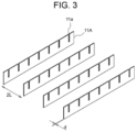
- first flat plates 11 with the openings of the notches 11a facing upward (hereinafter referred to as "first flat plates 11A") are arranged in parallel to each other.
- the first flat plates 11A are spaced from each other at predetermined distances 2L (twice the pitch of the notches 11a) in the direction of 60 degrees with respect to the plane of the first flat plate 11A.
- the first flat plates 11A are arranged side by side in parallel.
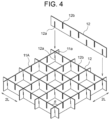
- a plurality of second flat plates 12 are engaged with the first flat plates 11A arranged in the first step. Specifically, the notches 12a which open to the lower sides of the second flat plates 12 are fitted in the notches 11a of the first flat plates 11A. It should be to be noted that the first flat plates 11A and the second flat plates 12 are not bonded to each other (the interfaces between the first and second flat plates are free of adhesives) in the second step.
- the second flat plates 12 are spaced from each other at the predetermined distances 2L in the direction of 60 degrees with respect to the plane of the second flat plate 12, and are arranged side by side in parallel.
- the intersecting angle ⁇ between the first flat plate 11A and the second flat plate 12 is 60 degrees.
- the notches 12a of the second flat plates 12 are inserted into every other one of the notches 11a of each of the first flat plates 11A.
- first flat plates 11 B a plurality of first flat plates 11 with the openings of the notches 11a facing downward
- first flat plates 11 B a plurality of first flat plates 11 with the openings of the notches 11a facing downward
- first flat plates 11 B a plurality of first flat plates 11 with the openings of the notches 11a facing downward
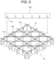
- first flat plates 11B are engaged with the first flat plates 11A and the second flat plates 12 assembled in the second step.
- the notches 11a of the first flat plates 11B are fitted in the empty notches 11a of the first flat plates 11A, which have not yet received the second flat plates 12, and the notches 12b, which open to the upper sides of the second flat plates 12.
- the first flat plates 11A and the first flat plates 11B are not bonded to each other and the second flat plates 12 and the first flat plates 11B are not bonded to each other.
- the first flat plates 11B are spaced from each other at the predetermined distances 2L in the direction of 60 degrees with respect to the plane of the first flat plate 11B.
- the first flat plates 11B are arranged side by side in parallel.
- the intersecting angle ⁇ ' between the first flat plate 11A and the first flat plate 11B is 60 degrees and the intersecting angle ⁇ " between the second flat plate 12 and the first flat plate 11B is also 60 degrees.
- the honeycomb-like core member 10 is manufactured.
- the first flat plates 11 shown in FIG. 1 are used in the first step and the third step in the assembling process for the core member 10.
- the second flat plates 12 shown in FIG. 2 are used only in the second step. Therefore, the number of the first flat plates 11 used for the core member 10 is greater than the number of the second flat plates 12.
- FIG. 6 is a plan view of the honeycomb-like core member 10 of this embodiment.
- the core member 10 includes the first flat plates 11A and 11B and the second flat plates 12.
- the notches of these flat plates are engaged with each other such that the flat plates intersect each other at an angle of 60 degrees.
- a plurality of hexagonal cylindrical portions (regular hexagonal cells) 13 and a plurality of triangular cylindrical portions (equilateral triangular cells) 14 are defined by the first flat plates 11A and 11B and the second flat plates 12.
- a conventional (or ordinary) honeycomb core when viewed from the top (in a plan view), is an assemblage of regular hexagonal cells (equilateral hexagonal cells).
- the core member 10 of this embodiment has a configuration in which the cells of the equilateral triangle are arranged around the cells of the equilateral hexagon. Therefore, the core member 10 of this embodiment is not called a true honeycomb core, but a honeycomb-like core (a quasi honeycomb core). However, the core member 10 can have the same strength as that of an ordinary honeycomb core.
- the core member 10 of this embodiment is constituted by CFRP
- the core member 10 can be a honeycomb-like core member having CFRP properties such as high specific stiffness, a small density and a small thermal expansion coefficient.
- a plurality of hexagonal cylindrical CFRP members 101 as shown in FIG. 7(a) are used in a manufacturing method. Specifically, the CRRP members 101 are arranged side by side without a gap and bonded to each other as shown in FIG. 7(b) .
- this manufacturing method requires a step of forming a CFRP member to a hexagonal cylindrical shape, a step of preparing and arranging a large number of CFRP members 101 and a step of bonding the CFRP members. This manufacturing method is complicated.
- a plate member is bonded to the top of the core member and another plate member is attached (bonded) to the bottom of the core member.
- a thermosetting adhesive is used for attaching the plate members to the core member, and the honeycomb core is heated at the time of attaching the plate members. If the interior of the honeycomb core is sealed (closed), a pressure difference arises between the inside and the outside of the sealed space upon finishing the attachment of the plate members and lowering the temperature. This pressure difference may cause distortions to occur in the structure. Furthermore, even during use of the structure, the above-mentioned pressure difference arises as the environmental temperature changes. This may also cause distortions to occur in the structure.
- the walls of the hexagonal cylinder portions need to have openings that communicate to the outside for leakage of the inside air to the outside. This makes the manufacturing process further complicated.
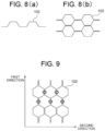
- a CFRP member 102 is bent at a plurality of positions with equal intervals as shown in FIG. 8(a) such that the CFRP member 102 has a zigzag shape, and a plurality of such CFRP members are prepared. Then, the CFRP members 102 are partially bonded as shown in FIG. 8(b) to form a plurality of hexagonal cylinder portions.
- the honeycomb core created by bonding the CFRP members 102 as shown in FIG. 8(b) includes a mixture of portions where the thickness of the wall of the honeycomb core is doubled because two planar segments of the CFRP members are bonded to each other (the segments indicated by the circle in FIG. 9 ) and portions where the thickness of the wall is unchanged because a single planar segment of the CFRP member exists, as shown in FIG. 9 . If the direction parallel to the wall whose thickness becomes double (ribbon direction) is referred to as a first direction and the direction perpendicular to the first direction is referred to as a second direction, the mechanical properties and thermal properties of the honeycomb core, such as the strength, rigidity and thermal expansion coefficient, in the first direction are different from those in the second direction.
- honeycomb core is used, for example, as a core member of a stage of a processing machine to which processing precision is required. This is because there is a possibility that distortion may occur on the stage surface due to a force applied to the stage, a temperature change of the environment in which the device is placed, or the like.
- the core member 10 of this embodiment is constructed by engaging the notches of the comb-teeth-shaped flat plates with each other such that the flat plates intersect each other. Therefore, the core member does not have a portion (or portions) where the flat segments overlap. In each of the portions where the flat plates 11A, 11B and 12 intersect (i.e., the notches of the flat plates), the flat plates are in contact with each other, but they are in partial contact, and the flat plates are not firmly fixed to each other by an adhesive or the like.
- the core member of this embodiment has no anisotropy in mechanical and thermal characteristics, i.e., the mechanical and thermal characteristics of the core member in the first direction are the same as those in the second direction. Thus, it is possible to suppress or avoid the generation of distortions due to a temperature change or the like.
- the core member 10 of this embodiment can be manufactured by simply fitting the notches of the comb-shaped flat plates into the notches of the comb-shaped flat plates. Therefore, a special and dedicated processing machine and/or a special and dedicated assembling machine is unnecessary, and accordingly, the core member of this embodiment can be produced at low cost.
- the length f of the notch formed in the flat plate 11, 12 is longer than a half of the length g of the short side of the flat plate.
- a gap can be formed at (or in the vicinity of) every intersecting portion of every two flat plates (at the engaging portion of every two notches of every two flat plates).
- This gap serves as the above-described hole for leakage of the air to the outside. That is, the notches formed to allow the flat plates to intersect each other also serve as the holes for leakage of the air to the outside. Therefore, even when the plate members are attached to the top and bottom of the core member 10, the inside of each of the hexagonal cylindrical portions 13 and the inside of each of the triangular cylindrical portions 14 of the core member 10 are not sealed from the outside. Therefore, the step of forming holes for air leakage is not required. This reduces the production time of the core member 10 and contributes to the cost reduction of the core member 10.
- the width w of the notch 11a, 12a, 12b formed in the flat plate is greater than the thickness of the flat plate.
- the width w of the notch is set to a value that allows a gap to be left at the interface between every two engaged notches of every two flat plates when the two flat plates are engaged with each other at the predetermined angle. Every two flat plates are engaged with each other at the intersecting angle of 60 degrees in this embodiment, and therefore the width w of each of the notches is set to a sum of a first value and a second value.
- the first value allows the two flat plates to engage with each other at the angle of 60 degrees (i.e., the first value is decided based on the thickness of the flat plate (design value of the flat plate) d and the intersecting angle ⁇ (60 degrees) of the plates).
- the second value is predetermined play (margin). The play is preferably set in consideration of a manufacturing error or tolerance of the thickness of the flat plate.
- the play of the width w of the notch is set to a small value to such an extent that the buckling does not occur, i.e., to such an extent that the initial posture of the flat plate does not become oblique.
- the core member 10 of this embodiment is a honeycomb-like core member that has the uniform (same) mechanical properties and thermal characteristics in a plane perpendicular to the thickness direction, does not require a special processing machine and does not need a machining step for making air leakage holes.
- the core member 10 of this embodiment can be used as a core member of various structures.
- two plate members 21 may be disposed to sandwich the core member 10 from above and below and bonded to the top and bottom of the core member 10 with bonding members 22 to obtain a panel-like structure 20.
- Each of the bonding members (adhesive members) 22 may be a sheet-like adhesive or a liquid adhesive. It is desirable that the core member 10 and the plate members 21 are made of the same material. By using the same material, the thermal expansion coefficient of the core member 10 becomes equal to the thermal expansion coefficient of the plate member 21, and therefore it is possible to suppress or avoid the distortion of the structure 20 due to temperature changes.
- the material of the core member 10 is CFRP and the material of the plate members 21 is also CFRP, it is possible to make a strong panel-shaped structure 20 that has light weight and generates small thermal deformation (small thermal expansion).
- CFRP has a small coefficient of thermal expansion in the direction parallel to the fiber and a small fluctuation (strain) due to heat, in the direction parallel to the fiber. Therefore, if the direction of the fibers of CFRP is aligned with a direction parallel to the short side of each of the flat plates of the core member 10, it is possible to prevent surface fluctuations (deformations and/or strains) in a direction perpendicular to the surface of the plate member 21, which would otherwise be caused by temperature changes.
- the CFRP plate that constitutes each of the flat plates of the core member 10 is a cross-ply laminate (multilayer plate) in which the prepregs are laminated such that the directions of the fibers of the prepregs become the angle of 0 degree and the angle of 90 degrees alternately.
- the directions of the fibers in the cross-ply laminate may also include an angle of 45 degrees (intermediate angle) and/or an angle of 60 degrees (another intermediate angle) in addition to the angle of 0 degree and the angle of 90 degrees.
- Use of such laminate of CFRP gives the core member 10 the isotropy in terms of the stiffness and expansion/contraction.
- the core member 10 may be used in various applications and structures.
- Such structure 20 may be used, for example, as building walls, aircraft bodies, space equipment, stages of large processing machines, and the like.
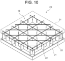
- each of the hexagonal cylindrical portions 13 having the equilateral hexagonal shape and the triangular cylindrical portions 14 having the equilateral triangular shape are formed in the core member 10 of the above-described embodiment, each of the hexagonal cylindrical portions 13 is not limited to the equilateral hexagonal shape and each of the triangular cylindrical portions 14 is not limited to the equilateral triangular shape.
- a core member 10A may have hexagonal cylindrical portions 13A and triangular cylindrical portions 14A.
- the core member 10A shown in FIG. 11 includes a plurality of first flat plates 11A, a plurality of second flat plates 12, and a plurality of third flat plates 15.
- the third flat plate 15 has the same configuration as the first flat plate 11B except for the distance (pitch) between every two adjacent notches.
- the intersecting angle ⁇ between the first flat plate 11A and the second flat plate 12 is 120 degrees
- the intersecting angle ⁇ ' between the first flat plate 11A and the third flat plate 15 is 30 degrees
- the intersecting angle ⁇ " between the second flat plate 12 and the third flat plate 15 is 30 degrees.
- the distance between every two adjacent third flat plates 15 is denoted by L.
- the intersecting angle of the flat plates is not limited to the above-mentioned angle, i.e., it can be any suitable angle. It should be noted, however, that if the flat plates are engaged with each other such that the flat plates cross at the angle of 60 degrees, the core member has excellent stability, which is preferable.
- honeycomb-like core member 10 is formed using two types of flat plates in the above-described embodiment, three or more types of flat plates may be used to form the honeycomb-like core member.
- the notches of the second flat member 12 are formed at equal intervals (pitches) and shifted from each other by a half of the pitch in the above-described embodiment, the notches of the second flat member may not be formed at equal intervals and/or may not be shifted from each other by a half of the pitch.
- the cross-sectional shapes of the triangular cylindrical portions made around the hexagonal cylindrical portions have the different sizes from those shown in FIG 6 . Even if there is a certain difference in the size of each of the triangular cylindrical portions, there is no problem in the strength of the core member.
Landscapes
- Engineering & Computer Science (AREA)
- Architecture (AREA)
- Civil Engineering (AREA)
- Structural Engineering (AREA)
- Mechanical Engineering (AREA)
- Aviation & Aerospace Engineering (AREA)
- Life Sciences & Earth Sciences (AREA)
- Wood Science & Technology (AREA)
- Laminated Bodies (AREA)
- Panels For Use In Building Construction (AREA)
Claims (9)
- Kernelement (10), das eine Vielzahl von flachen Plattenelementen (11, 11A, 11B, 12) umfasst, wobei jedes der Vielzahl von flachen Plattenelementen eine rechteckige Form hat, wobei jedes der Vielzahl von flachen Plattenelementen einen Kammzahnabschnitt beinhaltet, wobei der Kammzahnabschnitt durch eine Vielzahl von Kerben (11a, 12a, 12b) gekennzeichnet ist, die in jedem der Vielzahl von flachen Plattenelementen so ausgebildet ist, dass sich die Vielzahl von Kerben parallel zu einer kurzen Seite der rechteckigen Form erstreckt und zu mindestens einer der langen Seiten der rechteckigen Form offen ist,wobei die Vielzahl der Kerben (11a, 12a, 12b) der Vielzahl der flachen Plattenelemente (11, 11A, 11B, 12) miteinander in Eingriff steht, so dass die Vielzahl der flachen Plattenelemente einander kreuzt und die sich kreuzenden flachen Plattenelemente eine Vielzahl zylindrischer Abschnitte mit einer dreieckigen Zylinderform (14) bilden,dadurch gekennzeichnet, dassdie sich kreuzenden flachen Plattenelemente eine Vielzahl von ersten zylindrischen Abschnitten bilden, die jeweils eine sechseckige Zylinderform (13) haben, und eine Vielzahl von zweiten zylindrischen Abschnitten, die jeweils eine dreieckige Zylinderform (14) haben, undeine Breite (w) jeder der Kerben (11a, 12a, 12b) auf einen Wert eingestellt ist, der einen Spalt in der Nähe jeder der Kerben bildet, wenn die flachen Plattenelemente (11, 11A, 11B, 12) miteinander in Eingriff sind.
- Kernelement nach Anspruch 1, wobei die Vielzahl der Kerben so ineinandergreift, dass die Vielzahl der flachen Plattenelemente einander in einem Winkel (θ, θ', θ") von 60 Grad kreuzt.
- Kernelement nach Anspruch 1 oder 2, wobei die Vielzahl der die Kammzahnabschnitte aufweisenden flachen Plattenelemente aufweist:eine Vielzahl von ersten flachen Plattenelementen (11, 11A, 11B), von denen jedes die Vielzahl von Kerben (11a) zu einer der langen Seiten der rechteckigen Form in gleichen Abständen (L) offen hat, undeine Vielzahl von zweiten flachen Plattenelementen (12), von denen jedes die Vielzahl an Kerben (12a) zu der einen der langen Seiten der rechteckigen Form in gleichen Abständen (2L) offen hat und die Vielzahl an Kerben (12b) zu der anderen der langen Seiten der rechteckigen Form in den gleichen Abständen (2L) offen hat, wobei die Vielzahl an Kerben, die zu der anderen der langen Seiten offen ist, gegenüber der Vielzahl an Kerben, die zu der einen der langen Seiten offen ist, um eine Hälfte (L) des Abstandes (2L) verschoben ist.
- Kernelement nach einem der Ansprüche 1 bis 3, wobei eine Länge (f) jeder der Kerben (11a, 12a, 12b) länger als eine Hälfte einer Länge (g) der kurzen Seite der rechteckigen Form ist.
- Kernelement nach einem der Ansprüche 1 bis 4, wobei jedes der flachen Plattenelemente aus einem kohlenstofffaserverstärkten Kunststoff hergestellt ist, in den eine Vielzahl von Prepregs laminiert ist.
- Kernelement nach Anspruch 5, wobei sich Fasern des kohlenstofffaserverstärkten Kunststoffs in einer Richtung parallel zur kurzen Seite der rechteckigen Form erstrecken.
- Kernelement nach Anspruch 5, wobei der kohlenstofffaserverstärkte Kunststoff ein Kreuzlagenlaminat ist.
- Verfahren zur Herstellung eines Kernelements (10) mit einer Vielzahl von zylindrischen Abschnitten, wobei das Verfahren umfasst:Herstellen einer Vielzahl von flachen Plattenelementen (11, 11A, 11B, 12), wobei jedes der Vielzahl von flachen Plattenelementen eine rechteckige Form hat und einen Kammzahnabschnitt beinhaltet, so dass der Kammzahnabschnitt eine Vielzahl von Kerben (11a, 12a, 12b) aufweist, die zu mindestens einer der langen Seiten einer rechteckigen Form offen ist und sich parallel zu einer kurzen Seite der rechteckigen Form erstreckt, undIneinanderfügen der Kerben, so dass die Vielzahl der flachen Plattenelemente einander kreuzt,dadurch gekennzeichnet, dassdie sich kreuzenden flachen Plattenelemente eine Vielzahl von ersten zylindrischen Abschnitten bilden, die jeweils eine sechseckige Zylinderform (13) haben, und eine Vielzahl von zweiten zylindrischen Abschnitten, die jeweils eine dreieckige Zylinderform (14) haben,und dadurch, dasseine Breite (w) jeder der Kerben (11a, 12a, 12b) auf einen Wert eingestellt ist, der einen Spalt in der Nähe jeder der Kerben bildet, wenn die flachen Plattenelemente (11, 11A, 11B, 12) miteinander in Eingriff sind.
- Struktur (20), umfassend:das Kernelement (10) nach einem der Ansprüche 1 bis 7 undPlattenelemente (21), die mit gegenüberliegenden Seiten des Kernelements verbunden sind.
Applications Claiming Priority (2)
| Application Number | Priority Date | Filing Date | Title |
|---|---|---|---|
| JP2019205877A JP7365203B2 (ja) | 2019-11-14 | 2019-11-14 | 芯材および構造体 |
| PCT/JP2020/029075 WO2021095303A1 (ja) | 2019-11-14 | 2020-07-29 | 芯材および構造体 |
Publications (3)
| Publication Number | Publication Date |
|---|---|
| EP4060140A1 EP4060140A1 (de) | 2022-09-21 |
| EP4060140A4 EP4060140A4 (de) | 2023-12-20 |
| EP4060140B1 true EP4060140B1 (de) | 2024-12-04 |
Family
ID=75912016
Family Applications (1)
| Application Number | Title | Priority Date | Filing Date |
|---|---|---|---|
| EP20887381.0A Active EP4060140B1 (de) | 2019-11-14 | 2020-07-29 | Kernelement und verfahren zu seiner herstellung |
Country Status (6)
| Country | Link |
|---|---|
| US (1) | US12226986B2 (de) |
| EP (1) | EP4060140B1 (de) |
| JP (1) | JP7365203B2 (de) |
| KR (1) | KR102745301B1 (de) |
| CN (1) | CN115210437A (de) |
| WO (1) | WO2021095303A1 (de) |
Families Citing this family (3)
| Publication number | Priority date | Publication date | Assignee | Title |
|---|---|---|---|---|
| CN116749905A (zh) * | 2023-07-19 | 2023-09-15 | 奇瑞汽车股份有限公司 | 用于车辆的吸能装置及车辆 |
| CN220882697U (zh) * | 2023-08-22 | 2024-05-03 | 永丰余投资控股股份有限公司 | 一种梳形复合板、复合板以及板材连接结构 |
| CN118744569A (zh) * | 2024-07-22 | 2024-10-08 | 武汉现代精工机械股份有限公司 | 一种蜂窝板及其成型工艺 |
Family Cites Families (15)
| Publication number | Priority date | Publication date | Assignee | Title |
|---|---|---|---|---|
| US2490586A (en) * | 1948-04-21 | 1949-12-06 | Craige L Embree | Cellular structure |
| US2676738A (en) | 1952-10-03 | 1954-04-27 | Herrick Helen | Harness for hearing aid units |
| GB1177933A (en) * | 1966-02-11 | 1970-01-14 | British Gypsum Ltd | Building Panels with Cellular Core |
| JP2676738B2 (ja) | 1987-06-29 | 1997-11-17 | 三菱電機株式会社 | 繊維強化プラスチック製反射鏡 |
| US4917934A (en) * | 1989-04-27 | 1990-04-17 | Corning Incorporated | Telescope mirror blank and method of production |
| JP3231570B2 (ja) * | 1995-02-01 | 2001-11-26 | 昭和飛行機工業株式会社 | 繊維強化プラスチック製のハニカム構造体 |
| US5741445A (en) * | 1996-02-06 | 1998-04-21 | Cvd, Incorporated | Method of making lightweight closed-back mirror |
| JP3434254B2 (ja) * | 1999-12-27 | 2003-08-04 | 侃 田代 | 立体トラス複合板 |
| JP2001262771A (ja) * | 2000-03-23 | 2001-09-26 | Daiken Trade & Ind Co Ltd | パネル用芯材及びそれを用いたパネル |
| CN1301850C (zh) * | 2004-02-18 | 2007-02-28 | 冷鹭浩 | 一种矩形塑料蜂窝内芯复合板 |
| JP2008212787A (ja) * | 2007-03-01 | 2008-09-18 | Denso Corp | 排ガス浄化フィルタ |
| US10093039B2 (en) * | 2013-03-08 | 2018-10-09 | Stratasys, Inc. | Three-dimensional parts having interconnected Hollow patterns, method of manufacturing and method of producing composite part |
| EP2783838B1 (de) * | 2013-03-27 | 2015-11-18 | Airbus Operations GmbH | Verbundverstärkungskomponente, Strukturelement, Flugzeug oder Raumfahrzeug und Verfahren zur Herstellung der Verbundverstärkungskomponente |
| DE102015010436B4 (de) * | 2015-08-14 | 2019-01-24 | Airbus Defence and Space GmbH | Wabenkern für dimensionsstabile Sandwichbauteile, dessen Verwendung, Sandwichplatte mit diesem Wabenkern und Verfahren zur Herstellung des Wabenkerns |
| CN205149038U (zh) * | 2015-10-12 | 2016-04-13 | 重庆市皓邦工业有限公司 | 组合式纸蜂窝夹心复合板 |
-
2019
- 2019-11-14 JP JP2019205877A patent/JP7365203B2/ja active Active
-
2020
- 2020-07-29 US US17/756,026 patent/US12226986B2/en active Active
- 2020-07-29 CN CN202080079117.7A patent/CN115210437A/zh active Pending
- 2020-07-29 WO PCT/JP2020/029075 patent/WO2021095303A1/ja not_active Ceased
- 2020-07-29 KR KR1020227018880A patent/KR102745301B1/ko active Active
- 2020-07-29 EP EP20887381.0A patent/EP4060140B1/de active Active
Also Published As
| Publication number | Publication date |
|---|---|
| WO2021095303A1 (ja) | 2021-05-20 |
| KR20220092966A (ko) | 2022-07-04 |
| JP7365203B2 (ja) | 2023-10-19 |
| EP4060140A1 (de) | 2022-09-21 |
| KR102745301B1 (ko) | 2024-12-24 |
| JP2021079547A (ja) | 2021-05-27 |
| US20220396049A1 (en) | 2022-12-15 |
| EP4060140A4 (de) | 2023-12-20 |
| US12226986B2 (en) | 2025-02-18 |
| CN115210437A (zh) | 2022-10-18 |
Similar Documents
| Publication | Publication Date | Title |
|---|---|---|
| EP4060140B1 (de) | Kernelement und verfahren zu seiner herstellung | |
| Del Broccolo et al. | AUXHEX–A Kirigami inspired zero Poisson’s ratio cellular structure | |
| EP2737995B1 (de) | Faserverstärktes verbundmaterial | |
| US6553734B1 (en) | Composite structural panel with undulated body | |
| JP7249404B2 (ja) | 複合材料製パネル構造体およびその製造方法 | |
| KR101207472B1 (ko) | 피라미드형 트러스 구조체를 이용한 샌드위치 판재 및 그 제작 방법 | |
| US20140049814A1 (en) | Method of manufacturing advanced grid structure, advanced grid structure, and space telescope using advanced grid structure | |
| JP6238168B2 (ja) | 複合材構造 | |
| JP6377268B2 (ja) | ハニカムコア、ハニカムサンドイッチ構造体およびハニカムコアの製造方法 | |
| JP5861448B2 (ja) | サンドイッチパネルの製造方法 | |
| JP6112178B2 (ja) | サンドイッチパネルおよびサンドイッチパネルの製造方法 | |
| JP2025116355A (ja) | 格子状構造体および格子状構造体の製造方法 | |
| JP2022075629A (ja) | ハニカム構造体の製造方法及びハニカム構造体 | |
| US6579404B2 (en) | Method of making precision geometry advanced composite honeycomb material for spacecraft applications and honeycomb material made thereby | |
| JP7118312B1 (ja) | 積層体、積層体製造方法、及び宇宙構造物 | |
| JP6080789B2 (ja) | 繊維強化プラスチック製の継手部材、及び繊維強化プラスチック製の継手部材の製造方法 | |
| JPH0885178A (ja) | ハニカムサンドイッチパネル | |
| JP7559630B2 (ja) | ハニカムコア | |
| CN115352078B (zh) | 复合材料蜂窝及其制备方法 | |
| US11840362B2 (en) | Support body and support body mounting method | |
| JP2012153109A (ja) | 繊維強化プラスチック板及びその製造方法 | |
| JP7198701B2 (ja) | 繊維強化プラスチック複合材、繊維強化プラスチックプリフォーム、及び繊維強化プラスチック中間基材 | |
| JPH08281849A (ja) | ハニカムパネルおよびその製造方法 | |
| JP2006249797A (ja) | パネル及びその製造方法 |
Legal Events
| Date | Code | Title | Description |
|---|---|---|---|
| STAA | Information on the status of an ep patent application or granted ep patent |
Free format text: STATUS: THE INTERNATIONAL PUBLICATION HAS BEEN MADE |
|
| PUAI | Public reference made under article 153(3) epc to a published international application that has entered the european phase |
Free format text: ORIGINAL CODE: 0009012 |
|
| STAA | Information on the status of an ep patent application or granted ep patent |
Free format text: STATUS: REQUEST FOR EXAMINATION WAS MADE |
|
| 17P | Request for examination filed |
Effective date: 20220523 |
|
| AK | Designated contracting states |
Kind code of ref document: A1 Designated state(s): AL AT BE BG CH CY CZ DE DK EE ES FI FR GB GR HR HU IE IS IT LI LT LU LV MC MK MT NL NO PL PT RO RS SE SI SK SM TR |
|
| DAV | Request for validation of the european patent (deleted) | ||
| DAX | Request for extension of the european patent (deleted) | ||
| A4 | Supplementary search report drawn up and despatched |
Effective date: 20231121 |
|
| RIC1 | Information provided on ipc code assigned before grant |
Ipc: B29D 99/00 20100101ALI20231115BHEP Ipc: B29D 24/00 20060101ALI20231115BHEP Ipc: B32B 3/12 20060101ALI20231115BHEP Ipc: B64C 1/00 20060101ALI20231115BHEP Ipc: E04C 2/36 20060101AFI20231115BHEP |
|
| GRAP | Despatch of communication of intention to grant a patent |
Free format text: ORIGINAL CODE: EPIDOSNIGR1 |
|
| STAA | Information on the status of an ep patent application or granted ep patent |
Free format text: STATUS: GRANT OF PATENT IS INTENDED |
|
| RIC1 | Information provided on ipc code assigned before grant |
Ipc: E04C 2/22 20060101ALI20240710BHEP Ipc: B32B 5/02 20060101ALI20240710BHEP Ipc: B32B 3/06 20060101ALI20240710BHEP Ipc: B29D 99/00 20100101ALI20240710BHEP Ipc: B29D 24/00 20060101ALI20240710BHEP Ipc: B32B 3/12 20060101ALI20240710BHEP Ipc: B64C 1/00 20060101ALI20240710BHEP Ipc: E04C 2/36 20060101AFI20240710BHEP |
|
| INTG | Intention to grant announced |
Effective date: 20240722 |
|
| GRAS | Grant fee paid |
Free format text: ORIGINAL CODE: EPIDOSNIGR3 |
|
| GRAJ | Information related to disapproval of communication of intention to grant by the applicant or resumption of examination proceedings by the epo deleted |
Free format text: ORIGINAL CODE: EPIDOSDIGR1 |
|
| GRAL | Information related to payment of fee for publishing/printing deleted |
Free format text: ORIGINAL CODE: EPIDOSDIGR3 |
|
| STAA | Information on the status of an ep patent application or granted ep patent |
Free format text: STATUS: REQUEST FOR EXAMINATION WAS MADE |
|
| P01 | Opt-out of the competence of the unified patent court (upc) registered |
Free format text: CASE NUMBER: APP_49428/2024 Effective date: 20240830 |
|
| GRAP | Despatch of communication of intention to grant a patent |
Free format text: ORIGINAL CODE: EPIDOSNIGR1 |
|
| STAA | Information on the status of an ep patent application or granted ep patent |
Free format text: STATUS: GRANT OF PATENT IS INTENDED |
|
| GRAA | (expected) grant |
Free format text: ORIGINAL CODE: 0009210 |
|
| STAA | Information on the status of an ep patent application or granted ep patent |
Free format text: STATUS: THE PATENT HAS BEEN GRANTED |
|
| INTC | Intention to grant announced (deleted) | ||
| INTG | Intention to grant announced |
Effective date: 20241011 |
|
| AK | Designated contracting states |
Kind code of ref document: B1 Designated state(s): AL AT BE BG CH CY CZ DE DK EE ES FI FR GB GR HR HU IE IS IT LI LT LU LV MC MK MT NL NO PL PT RO RS SE SI SK SM TR |
|
| REG | Reference to a national code |
Ref country code: CH Ref legal event code: EP |
|
| REG | Reference to a national code |
Ref country code: DE Ref legal event code: R096 Ref document number: 602020042768 Country of ref document: DE |
|
| REG | Reference to a national code |
Ref country code: IE Ref legal event code: FG4D |
|
| REG | Reference to a national code |
Ref country code: DE Ref legal event code: R081 Ref document number: 602020042768 Country of ref document: DE Owner name: SUZUKI INDUSTRY CO., LTD., NAKATSUGAWA-SHI, JP Free format text: FORMER OWNERS: SUZUKI INDUSTRY CO., LTD., NAKATSUGAWA-SHI, GIFU, JP; USHIO DENKI KABUSHIKI KAISHA, TOKYO, JP Ref country code: DE Ref legal event code: R081 Ref document number: 602020042768 Country of ref document: DE Owner name: ADTEC ENGINEERING CO., LTD., JP Free format text: FORMER OWNERS: SUZUKI INDUSTRY CO., LTD., NAKATSUGAWA-SHI, GIFU, JP; USHIO DENKI KABUSHIKI KAISHA, TOKYO, JP |
|
| REG | Reference to a national code |
Ref country code: LT Ref legal event code: MG9D |
|
| REG | Reference to a national code |
Ref country code: NL Ref legal event code: MP Effective date: 20241204 |
|
| PG25 | Lapsed in a contracting state [announced via postgrant information from national office to epo] |
Ref country code: HR Free format text: LAPSE BECAUSE OF FAILURE TO SUBMIT A TRANSLATION OF THE DESCRIPTION OR TO PAY THE FEE WITHIN THE PRESCRIBED TIME-LIMIT Effective date: 20241204 |
|
| PG25 | Lapsed in a contracting state [announced via postgrant information from national office to epo] |
Ref country code: FI Free format text: LAPSE BECAUSE OF FAILURE TO SUBMIT A TRANSLATION OF THE DESCRIPTION OR TO PAY THE FEE WITHIN THE PRESCRIBED TIME-LIMIT Effective date: 20241204 |
|
| PG25 | Lapsed in a contracting state [announced via postgrant information from national office to epo] |
Ref country code: BG Free format text: LAPSE BECAUSE OF FAILURE TO SUBMIT A TRANSLATION OF THE DESCRIPTION OR TO PAY THE FEE WITHIN THE PRESCRIBED TIME-LIMIT Effective date: 20241204 |
|
| PG25 | Lapsed in a contracting state [announced via postgrant information from national office to epo] |
Ref country code: ES Free format text: LAPSE BECAUSE OF FAILURE TO SUBMIT A TRANSLATION OF THE DESCRIPTION OR TO PAY THE FEE WITHIN THE PRESCRIBED TIME-LIMIT Effective date: 20241204 |
|
| PG25 | Lapsed in a contracting state [announced via postgrant information from national office to epo] |
Ref country code: NO Free format text: LAPSE BECAUSE OF FAILURE TO SUBMIT A TRANSLATION OF THE DESCRIPTION OR TO PAY THE FEE WITHIN THE PRESCRIBED TIME-LIMIT Effective date: 20250304 |
|
| PG25 | Lapsed in a contracting state [announced via postgrant information from national office to epo] |
Ref country code: GR Free format text: LAPSE BECAUSE OF FAILURE TO SUBMIT A TRANSLATION OF THE DESCRIPTION OR TO PAY THE FEE WITHIN THE PRESCRIBED TIME-LIMIT Effective date: 20250305 Ref country code: LV Free format text: LAPSE BECAUSE OF FAILURE TO SUBMIT A TRANSLATION OF THE DESCRIPTION OR TO PAY THE FEE WITHIN THE PRESCRIBED TIME-LIMIT Effective date: 20241204 |
|
| PG25 | Lapsed in a contracting state [announced via postgrant information from national office to epo] |
Ref country code: RS Free format text: LAPSE BECAUSE OF FAILURE TO SUBMIT A TRANSLATION OF THE DESCRIPTION OR TO PAY THE FEE WITHIN THE PRESCRIBED TIME-LIMIT Effective date: 20250304 |
|
| PG25 | Lapsed in a contracting state [announced via postgrant information from national office to epo] |
Ref country code: NL Free format text: LAPSE BECAUSE OF FAILURE TO SUBMIT A TRANSLATION OF THE DESCRIPTION OR TO PAY THE FEE WITHIN THE PRESCRIBED TIME-LIMIT Effective date: 20241204 |
|
| REG | Reference to a national code |
Ref country code: AT Ref legal event code: MK05 Ref document number: 1748303 Country of ref document: AT Kind code of ref document: T Effective date: 20241204 |
|
| PG25 | Lapsed in a contracting state [announced via postgrant information from national office to epo] |
Ref country code: SM Free format text: LAPSE BECAUSE OF FAILURE TO SUBMIT A TRANSLATION OF THE DESCRIPTION OR TO PAY THE FEE WITHIN THE PRESCRIBED TIME-LIMIT Effective date: 20241204 |
|
| PG25 | Lapsed in a contracting state [announced via postgrant information from national office to epo] |
Ref country code: PL Free format text: LAPSE BECAUSE OF FAILURE TO SUBMIT A TRANSLATION OF THE DESCRIPTION OR TO PAY THE FEE WITHIN THE PRESCRIBED TIME-LIMIT Effective date: 20241204 |
|
| PG25 | Lapsed in a contracting state [announced via postgrant information from national office to epo] |
Ref country code: IS Free format text: LAPSE BECAUSE OF FAILURE TO SUBMIT A TRANSLATION OF THE DESCRIPTION OR TO PAY THE FEE WITHIN THE PRESCRIBED TIME-LIMIT Effective date: 20250404 |
|
| PG25 | Lapsed in a contracting state [announced via postgrant information from national office to epo] |
Ref country code: PT Free format text: LAPSE BECAUSE OF FAILURE TO SUBMIT A TRANSLATION OF THE DESCRIPTION OR TO PAY THE FEE WITHIN THE PRESCRIBED TIME-LIMIT Effective date: 20250404 |
|
| PG25 | Lapsed in a contracting state [announced via postgrant information from national office to epo] |
Ref country code: EE Free format text: LAPSE BECAUSE OF FAILURE TO SUBMIT A TRANSLATION OF THE DESCRIPTION OR TO PAY THE FEE WITHIN THE PRESCRIBED TIME-LIMIT Effective date: 20241204 |
|
| PG25 | Lapsed in a contracting state [announced via postgrant information from national office to epo] |
Ref country code: AT Free format text: LAPSE BECAUSE OF FAILURE TO SUBMIT A TRANSLATION OF THE DESCRIPTION OR TO PAY THE FEE WITHIN THE PRESCRIBED TIME-LIMIT Effective date: 20241204 Ref country code: RO Free format text: LAPSE BECAUSE OF FAILURE TO SUBMIT A TRANSLATION OF THE DESCRIPTION OR TO PAY THE FEE WITHIN THE PRESCRIBED TIME-LIMIT Effective date: 20241204 |
|
| PG25 | Lapsed in a contracting state [announced via postgrant information from national office to epo] |
Ref country code: SK Free format text: LAPSE BECAUSE OF FAILURE TO SUBMIT A TRANSLATION OF THE DESCRIPTION OR TO PAY THE FEE WITHIN THE PRESCRIBED TIME-LIMIT Effective date: 20241204 |
|
| PG25 | Lapsed in a contracting state [announced via postgrant information from national office to epo] |
Ref country code: CZ Free format text: LAPSE BECAUSE OF FAILURE TO SUBMIT A TRANSLATION OF THE DESCRIPTION OR TO PAY THE FEE WITHIN THE PRESCRIBED TIME-LIMIT Effective date: 20241204 |
|
| PG25 | Lapsed in a contracting state [announced via postgrant information from national office to epo] |
Ref country code: IT Free format text: LAPSE BECAUSE OF FAILURE TO SUBMIT A TRANSLATION OF THE DESCRIPTION OR TO PAY THE FEE WITHIN THE PRESCRIBED TIME-LIMIT Effective date: 20241204 |
|
| REG | Reference to a national code |
Ref country code: DE Ref legal event code: R097 Ref document number: 602020042768 Country of ref document: DE |
|
| PG25 | Lapsed in a contracting state [announced via postgrant information from national office to epo] |
Ref country code: SE Free format text: LAPSE BECAUSE OF FAILURE TO SUBMIT A TRANSLATION OF THE DESCRIPTION OR TO PAY THE FEE WITHIN THE PRESCRIBED TIME-LIMIT Effective date: 20241204 |
|
| PG25 | Lapsed in a contracting state [announced via postgrant information from national office to epo] |
Ref country code: DK Free format text: LAPSE BECAUSE OF FAILURE TO SUBMIT A TRANSLATION OF THE DESCRIPTION OR TO PAY THE FEE WITHIN THE PRESCRIBED TIME-LIMIT Effective date: 20241204 |
|
| PGFP | Annual fee paid to national office [announced via postgrant information from national office to epo] |
Ref country code: DE Payment date: 20250604 Year of fee payment: 6 |
|
| PLBE | No opposition filed within time limit |
Free format text: ORIGINAL CODE: 0009261 |
|
| STAA | Information on the status of an ep patent application or granted ep patent |
Free format text: STATUS: NO OPPOSITION FILED WITHIN TIME LIMIT |
|
| REG | Reference to a national code |
Ref country code: CH Ref legal event code: L10 Free format text: ST27 STATUS EVENT CODE: U-0-0-L10-L00 (AS PROVIDED BY THE NATIONAL OFFICE) Effective date: 20251015 |
|
| 26N | No opposition filed |
Effective date: 20250905 |
|
| REG | Reference to a national code |
Ref country code: CH Ref legal event code: H13 Free format text: ST27 STATUS EVENT CODE: U-0-0-H10-H13 (AS PROVIDED BY THE NATIONAL OFFICE) Effective date: 20260224 |
|
| PG25 | Lapsed in a contracting state [announced via postgrant information from national office to epo] |
Ref country code: LU Free format text: LAPSE BECAUSE OF NON-PAYMENT OF DUE FEES Effective date: 20250729 |
|
| GBPC | Gb: european patent ceased through non-payment of renewal fee |
Effective date: 20250729 |
|
| REG | Reference to a national code |
Ref country code: BE Ref legal event code: MM Effective date: 20250731 |
|
| PG25 | Lapsed in a contracting state [announced via postgrant information from national office to epo] |
Ref country code: GB Free format text: LAPSE BECAUSE OF NON-PAYMENT OF DUE FEES Effective date: 20250729 |
|
| PG25 | Lapsed in a contracting state [announced via postgrant information from national office to epo] |
Ref country code: BE Free format text: LAPSE BECAUSE OF NON-PAYMENT OF DUE FEES Effective date: 20250731 |
|
| PG25 | Lapsed in a contracting state [announced via postgrant information from national office to epo] |
Ref country code: FR Free format text: LAPSE BECAUSE OF NON-PAYMENT OF DUE FEES Effective date: 20250731 |