EP4060161A1 - Douille de câble - Google Patents
Douille de câble Download PDFInfo
- Publication number
- EP4060161A1 EP4060161A1 EP21163391.2A EP21163391A EP4060161A1 EP 4060161 A1 EP4060161 A1 EP 4060161A1 EP 21163391 A EP21163391 A EP 21163391A EP 4060161 A1 EP4060161 A1 EP 4060161A1
- Authority
- EP
- European Patent Office
- Prior art keywords
- cable
- swivel
- kelly bar
- rotatable
- connection
- Prior art date
- Legal status (The legal status is an assumption and is not a legal conclusion. Google has not performed a legal analysis and makes no representation as to the accuracy of the status listed.)
- Granted
Links
Images



Classifications
-
- E—FIXED CONSTRUCTIONS
- E21—EARTH OR ROCK DRILLING; MINING
- E21B—EARTH OR ROCK DRILLING; OBTAINING OIL, GAS, WATER, SOLUBLE OR MELTABLE MATERIALS OR A SLURRY OF MINERALS FROM WELLS
- E21B17/00—Drilling rods or pipes; Flexible drill strings; Kellies; Drill collars; Sucker rods; Cables; Casings; Tubings
- E21B17/02—Couplings; joints
- E21B17/03—Couplings; joints between drilling rod or pipe and drill motor or surface drive, e.g. between drilling rod and hammer
-
- E—FIXED CONSTRUCTIONS
- E21—EARTH OR ROCK DRILLING; MINING
- E21B—EARTH OR ROCK DRILLING; OBTAINING OIL, GAS, WATER, SOLUBLE OR MELTABLE MATERIALS OR A SLURRY OF MINERALS FROM WELLS
- E21B19/00—Handling rods, casings, tubes or the like outside the borehole, e.g. in the derrick; Apparatus for feeding the rods or cables
- E21B19/02—Rod or cable suspensions
-
- E—FIXED CONSTRUCTIONS
- E21—EARTH OR ROCK DRILLING; MINING
- E21B—EARTH OR ROCK DRILLING; OBTAINING OIL, GAS, WATER, SOLUBLE OR MELTABLE MATERIALS OR A SLURRY OF MINERALS FROM WELLS
- E21B17/00—Drilling rods or pipes; Flexible drill strings; Kellies; Drill collars; Sucker rods; Cables; Casings; Tubings
- E21B17/02—Couplings; joints
- E21B17/04—Couplings; joints between rod or the like and bit or between rod and rod or the like
- E21B17/05—Swivel joints
-
- E—FIXED CONSTRUCTIONS
- E21—EARTH OR ROCK DRILLING; MINING
- E21B—EARTH OR ROCK DRILLING; OBTAINING OIL, GAS, WATER, SOLUBLE OR MELTABLE MATERIALS OR A SLURRY OF MINERALS FROM WELLS
- E21B17/00—Drilling rods or pipes; Flexible drill strings; Kellies; Drill collars; Sucker rods; Cables; Casings; Tubings
- E21B17/02—Couplings; joints
- E21B17/04—Couplings; joints between rod or the like and bit or between rod and rod or the like
- E21B17/07—Telescoping joints for varying drill string lengths; Shock absorbers
-
- F—MECHANICAL ENGINEERING; LIGHTING; HEATING; WEAPONS; BLASTING
- F16—ENGINEERING ELEMENTS AND UNITS; GENERAL MEASURES FOR PRODUCING AND MAINTAINING EFFECTIVE FUNCTIONING OF MACHINES OR INSTALLATIONS; THERMAL INSULATION IN GENERAL
- F16B—DEVICES FOR FASTENING OR SECURING CONSTRUCTIONAL ELEMENTS OR MACHINE PARTS TOGETHER, e.g. NAILS, BOLTS, CIRCLIPS, CLAMPS, CLIPS OR WEDGES; JOINTS OR JOINTING
- F16B7/00—Connections of rods or tubes, e.g. of non-circular section, mutually, including resilient connections
Definitions
- the invention relates to a rope swivel for connecting a rope or a bracket to a component that can be rotated relative to the rope or the bracket, in particular a Kelly bar, with a stationary first swivel part that can be attached to the rope or the bracket, and a rotatable second swivel part that rotatable and axially fixed on the standing first vertebral part and can be connected to the component, according to the preamble of claim 1.
- So-called rope swivels are used in particular on construction machinery when a rotationally driven component is to be suspended from a suspension cable or a suspension rod, and the rotation of the component should not be transmitted to the cable or the suspension rod.
- a rope swivel is, for example, from the EP 2 821 585 B1 known, in addition to the rotatable suspension on a cable, a torque arm is provided.
- This torque support connects the essentially non-rotatable supporting cable to the stator of a rotary bushing on a rotary driven Kelly bar for a drilling tool via the cable swivel.
- the additional arrangement of a rotary feedthrough in the area of the cable swivel allows the transmission of a liquid from the stationary support cable to the rotating drill pipe.
- a Kelly bar in which a rotary bushing is arranged below a cable suspension.
- a power flow is to reaches the rotary union so that it can be operated particularly gently and therefore with little maintenance.
- the invention is based on the object of specifying a cable swivel with which, in addition to a rotatable suspension of a component, an additional non-rotatable connection can be created at the same time.
- the cable swivel according to the invention is characterized in that the rotatable second swivel part is sleeve-shaped with an axial passage and that a connecting mandrel is formed on the stationary first swivel part or the rotatable component, which at least partially extends axially along the passage of the rotatable second swivel part.
- a basic idea of the invention consists in configuring a cable swivel with a sleeve-shaped rotatable swivel part which is non-rotatably connected to the rotatable component to be attached.
- the second rotatable swivel part is rotatably mounted on the fixed first swivel part, which is connected to the cable or the fixed mount, such as a crane hook or a carrying rod.
- the sleeve-like design of the rotatable second vertebral part makes it possible to arrange a connecting mandrel in the passage formed thereby, which is firmly connected to the stationary first vertebral part or can be connected in a rotationally fixed manner.
- the connecting mandrel can either be arranged fixedly on the first vertebral part or on the component to be attached, which can have a rotary feedthrough.
- the invention makes it possible, in addition to the actual rotatable suspension of a component on a cable swivel, to also provide a non-rotatable connection to a subcomponent, such as a rotary feedthrough, if possible without screwing lines to the component to be suspended.
- a preferred embodiment of the invention is that the connecting mandrel is tubular and has a fluid line along its tubular interior, a data line, an electrical power line and/or a hydraulic line runs.
- the cable swivel can not only be used as a simple joint element for suspension. Rather, the tubular connecting mandrel makes it possible to transmit a liquid, a gas, electrical current, data and/or another medium directly through the cable swivel.
- connection section for forming a positive and/or non-positive connection with a counter-connection section is formed on the free end of the connecting mandrel.
- the mating connection portion may be fitted to the component to be attached.
- the connection section can in particular be a plug, which produces a desired connection to the counter-connection section by simply plugging it together axially.
- the connection can be a purely mechanical connection and/or a wiring connection.
- the connecting section can be connected to a stator of a rotary feedthrough.
- the rotary feedthrough can be provided on the component to be attached.
- the stator to be attached is thus non-rotatably connected to the first swivel part of the cable swivel.
- the cable swivel can preferably be suspended from a cable which is essentially torsionally rigid.
- the connecting mandrel it is particularly expedient for the connecting mandrel to have a connection for a feed line at its end remote from the passage.
- the connection can be formed in particular on an outside of the first vertebral part.
- a fluid, electrical power or data line corresponding to the support cable or the support rod can thus be connected to the first swivel part which is stationary relative to the rotationally drivable component. This enables a particularly efficient transmission of a fluid, of electrical power or of data.
- the invention also includes a Kelly bar arrangement with such a cable swivel according to the invention and a Kelly bar, which has a cable swivel at its upper end for attachment to a supporting cable and a connecting device for a tool, in particular a drilling tool, at its lower end.
- the Kelly bar can be a single Kelly bar or a telescopic Kelly bar.
- axially running drive rails are arranged in a basically known manner, which allow torque to be transmitted from an annular Kelly drive to the Kelly bar, which can be displaced axially thereto.
- a preferred embodiment of the Kelly bar arrangement according to the invention consists in the Kelly bar being connected in a rotationally fixed manner to the rotatable second vertebral part.
- the second swivel part thus rotates with the Kelly bar when it is driven in rotation.
- the axial flow of force of the cable swivel runs from the supporting cable via the first swivel part, which is fixed for this purpose, to the second swivel part, which is rotatably mounted thereon and is connected in a rotationally fixed manner to a suspension device of the Kelly bar.
- a particularly advantageous Kelly bar arrangement results from the fact that the Kelly bar has a rotary feedthrough at its upper end, which comprises a stator and a rotor, which is non-rotatably and axially firmly connected to the Kelly rod, and that the stator of the rotary feedthrough is non-rotatable and is detachably connected to the connecting mandrel of the cable swivel.
- the connecting mandrel of the cable swivel can thus have a supply for a fluid, electric power or data from a supply line supplied from the outside, which preferably runs at least partially parallel to the suspension cable.
- stator refers to the fixed part of the rotary feedthrough relative to the connecting mandrel and the first swivel part of the rope swivel.
- the rotor of the rotary feedthrough is the part of the rotary feedthrough within the meaning of the invention that is connected in a rotationally fixed manner to the Kelly rod that can be driven in rotation.
- a mating connection section is arranged on the stator, which is designed to match the connection section on the connection mandrel.
- the line connection can be formed, in particular, by simply plugging them together axially in accordance with a plug-in connection.
- An additional position securing, such as a screw connection or bolting, can be dispensed with.
- the line connection is designed as a detachable positive and/or non-positive connection for conducting a fluid, data and/or electric power.
- force-fitting elements that match one another such as springs or clamps, and/or positive-locking elements, such as keyway elements, can be formed on the plug-in elements.
- the plugs can also be designed in a non-round shape, for example with a polygonal cross section or with an oval cross section.
- Corresponding channels are provided for conducting a fluid, while corresponding lines, for example with sliding contact connections, are provided for conducting electrical current or data.
- the invention further includes a drilling device for drilling in the ground, with a carrier unit and a drilling drive for rotating a Kelly bar with a drilling tool, wherein a Kelly bar arrangement according to the invention is provided.
- the Kelly bar arrangement can be designed as previously described. The corresponding advantages can thus be achieved with the drill.
- the drilling tool is located at the lower end of the Kelly bar.
- the drilling tool can in particular be an auger, a drill bucket, a displacement drill, a rock drill or any other known drilling tool for foundation engineering or special foundation engineering.
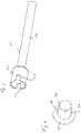
- the Kelly rod 20 is designed as a telescoping Kelly rod 20 with a tubular outer Kelly rod 22 and a tubular inner Kelly rod 24 arranged therein in a rotationally fixed but axially displaceable manner relative to the outer Kelly rod 22 .
- a tubular connection area 26 for connection to a cable swivel 40 is arranged.
- the rope swivel 40 is connected to a support rope, not shown, via which the Kelly bar 20 is held.
- a rotary feedthrough 30 is attached to a support plate, not shown.
- the kelly bar 20 is held in a vertical orientation on a mast via the suspension cable, for example when used on a drilling device, via the cable swivel 40, the kelly bar 20 being rotationally driven by an annular rotary drive for carrying out a kelly drilling method.
- the Kelly bar 20 can be placed on the rotary drive by means of an attachment ring 28 on the outer Kelly bar 22 .
- the cable swivel 40 prevents, in a manner known in principle, that the rotation of the rotary-driven Kelly bar 20 is transmitted to the carrying cable of the drilling device, which is non-rotatable for this purpose.
- the rope swivel 40 has a tubular first swivel part 41 with a sleeve body 42 . At its upper end, which faces away from the Kelly bar 20, this first swivel part 41 is fastened in a known manner by a transversely directed retaining bolt 44 to a suspension of the carrying cable.
- a rotary bearing 48 is arranged inside the sleeve body 42, with which a tubular second vortex part 50 can be rotated within the first vortex part 41, but is axially fixed is stored.
- the second swivel part 50 has a tubular outer sleeve 52 which protrudes axially in relation to the first swivel part 41 in the direction of the component to be attached, that is to say the Kelly rod 20 in the exemplary embodiment shown.
- the protruding connection end 53 of the second vertebral part 50 that is formed in this way can be plugged into the sleeve-shaped connection area 26 of the Kelly bar 20, as illustrated in FIG 1 is shown.
- the connecting end 53 of the cable swivel 40 is axially fixed and non-rotatably connected to the Kelly bar 20 via transversely directed connecting elements 18 .
- the connecting mandrel 60 has a tubular body 62 with a tubular interior 63 .
- the tubular body 62 is non-rotatably connected to the first vortex part 41 and opens into a feed channel 46 in the first vortex part 41.
- a connection section 64 with an enlarged diameter compared to the tubular body 62 is formed , as vividly in 2 is shown.
- a counter-connecting section 36 is provided on the rotary feedthrough 30 on the Kelly bar 20, which in 3 is shown in more detail.
- the mating connection section 36 is connected in a torque-proof manner to a stator of the rotary feedthrough 30 .
- the stator can be rotated with respect to a rotor 32 of the rotary feedthrough 30 , the rotor 32 being connected to the inner kelly rod 24 in a rotationally fixed and axially fixed manner via a support plate 29 .
- FIGS Figures 3 to 5 The mating of the connecting section 64 on the connecting mandrel 60 with the counter-connecting section 36 on the rotary feedthrough 30 is again closer in FIGS Figures 3 to 5 shown.
- a sleeve-shaped connecting section 64 with a larger diameter is formed on the tubular body 62 of the connecting mandrel 60 at the free end.
- two groove-like recesses 65 are introduced in the axial direction on the free end face of the connecting section 64 .
- two tongue-shaped webs 38 are formed on an outer side of the sleeve-shaped mating connection section 36, which can be pushed axially into the corresponding recesses 65, with a non-rotatable form-fitting connection being formed.
- a connecting flange 37 is provided for fastening the sleeve-shaped mating connection section 36 to the rotary leadthrough 30 .
Landscapes
- Engineering & Computer Science (AREA)
- Life Sciences & Earth Sciences (AREA)
- Geology (AREA)
- Mining & Mineral Resources (AREA)
- Mechanical Engineering (AREA)
- Physics & Mathematics (AREA)
- Environmental & Geological Engineering (AREA)
- Fluid Mechanics (AREA)
- General Life Sciences & Earth Sciences (AREA)
- Geochemistry & Mineralogy (AREA)
- General Engineering & Computer Science (AREA)
- Earth Drilling (AREA)
Priority Applications (4)
| Application Number | Priority Date | Filing Date | Title |
|---|---|---|---|
| EP21163391.2A EP4060161B1 (fr) | 2021-03-18 | 2021-03-18 | Douille de câble |
| US18/548,174 US12221837B2 (en) | 2021-03-18 | 2022-03-07 | Cable swivel |
| PCT/EP2022/055710 WO2022194591A1 (fr) | 2021-03-18 | 2022-03-07 | Pivot de câble |
| CN202280017262.1A CN116940741A (zh) | 2021-03-18 | 2022-03-07 | 绳索旋转部 |
Applications Claiming Priority (1)
| Application Number | Priority Date | Filing Date | Title |
|---|---|---|---|
| EP21163391.2A EP4060161B1 (fr) | 2021-03-18 | 2021-03-18 | Douille de câble |
Publications (3)
| Publication Number | Publication Date |
|---|---|
| EP4060161A1 true EP4060161A1 (fr) | 2022-09-21 |
| EP4060161B1 EP4060161B1 (fr) | 2023-06-28 |
| EP4060161C0 EP4060161C0 (fr) | 2023-06-28 |
Family
ID=75108183
Family Applications (1)
| Application Number | Title | Priority Date | Filing Date |
|---|---|---|---|
| EP21163391.2A Active EP4060161B1 (fr) | 2021-03-18 | 2021-03-18 | Douille de câble |
Country Status (4)
| Country | Link |
|---|---|
| US (1) | US12221837B2 (fr) |
| EP (1) | EP4060161B1 (fr) |
| CN (1) | CN116940741A (fr) |
| WO (1) | WO2022194591A1 (fr) |
Citations (3)
| Publication number | Priority date | Publication date | Assignee | Title |
|---|---|---|---|---|
| US5501287A (en) * | 1993-09-29 | 1996-03-26 | Ing. G. Klemm Bohrtechnik Gmbh | Drilling device with telescopic Kellybar |
| EP2821585B1 (fr) | 2013-07-03 | 2016-01-20 | Bauer Spezialtiefbau GmbH | Dispositif de forage et procédé de forage |
| EP3779117A1 (fr) * | 2019-08-16 | 2021-02-17 | BAUER Maschinen GmbH | Dispositif de tige d'entraînement pour un appareil de forage et procédé de traitement du sol |
Family Cites Families (6)
| Publication number | Priority date | Publication date | Assignee | Title |
|---|---|---|---|---|
| US4137974A (en) * | 1977-01-06 | 1979-02-06 | Smith International, Inc. | Hydraulically driven kelly crowd |
| CA2605260C (fr) * | 1997-12-27 | 2011-06-07 | Charles M. Helms | Dispositif de tete d'injection verrouillable et procede correspondant |
| EP2113632B1 (fr) * | 2008-04-28 | 2010-04-28 | BAUER Maschinen GmbH | Dispositif de raccordement destiné à former une introduction de liquide |
| CN102003587B (zh) * | 2010-11-15 | 2012-08-22 | 中国农业大学 | 一种真空装置用旋转接头 |
| CN202227998U (zh) * | 2011-08-25 | 2012-05-23 | 上海中联重科桩工机械有限公司 | 钻杆的芯节杆 |
| CN111379530A (zh) * | 2020-05-12 | 2020-07-07 | 徐州海润行知重工机械有限公司 | 内置气体传输通道的旋挖钻机提引器 |
-
2021
- 2021-03-18 EP EP21163391.2A patent/EP4060161B1/fr active Active
-
2022
- 2022-03-07 CN CN202280017262.1A patent/CN116940741A/zh active Pending
- 2022-03-07 WO PCT/EP2022/055710 patent/WO2022194591A1/fr not_active Ceased
- 2022-03-07 US US18/548,174 patent/US12221837B2/en active Active
Patent Citations (3)
| Publication number | Priority date | Publication date | Assignee | Title |
|---|---|---|---|---|
| US5501287A (en) * | 1993-09-29 | 1996-03-26 | Ing. G. Klemm Bohrtechnik Gmbh | Drilling device with telescopic Kellybar |
| EP2821585B1 (fr) | 2013-07-03 | 2016-01-20 | Bauer Spezialtiefbau GmbH | Dispositif de forage et procédé de forage |
| EP3779117A1 (fr) * | 2019-08-16 | 2021-02-17 | BAUER Maschinen GmbH | Dispositif de tige d'entraînement pour un appareil de forage et procédé de traitement du sol |
Also Published As
| Publication number | Publication date |
|---|---|
| US20240141733A1 (en) | 2024-05-02 |
| WO2022194591A1 (fr) | 2022-09-22 |
| CN116940741A (zh) | 2023-10-24 |
| US12221837B2 (en) | 2025-02-11 |
| EP4060161B1 (fr) | 2023-06-28 |
| EP4060161C0 (fr) | 2023-06-28 |
Similar Documents
| Publication | Publication Date | Title |
|---|---|---|
| EP2048321B1 (fr) | Appareil de forage et procédé de fonctionnement d'un appareil de forage | |
| EP2495389B1 (fr) | Tiges de forage | |
| WO2011128427A2 (fr) | Dispositif de rotation pour un équipement auxiliaire d'un engin de travaux publics | |
| EP3877624B1 (fr) | Dispositif de tige d'entraînement pour un appareil de forage et procédé de traitement du sol | |
| EP2113632B1 (fr) | Dispositif de raccordement destiné à former une introduction de liquide | |
| EP2737159B1 (fr) | Manchon porte-outil recevant des outils de forage tubulaires présentant de différents diamètres | |
| EP1123784A2 (fr) | Adaptateur d'outil à l'interface d'un robot | |
| DE1239642B (de) | Erweiterungsbohrer | |
| EP4139554B1 (fr) | Dispositif de transmission de donnees et/ou de puissance sur un equipement de forage ou un treuil de manutention | |
| EP4060161B1 (fr) | Douille de câble | |
| EP2821585B1 (fr) | Dispositif de forage et procédé de forage | |
| EP3964650B1 (fr) | Système de changement rapide permettant de changer les accessoires sur une machine de construction | |
| EP3205794A1 (fr) | Système de poignée et procédé de montage | |
| DE4014752C2 (de) | Längsschneidarm für Vortriebs- und Abbauzwecke u. dgl. | |
| EP3882398B1 (fr) | Tige de forage et procédé pour mise à niveau d'un agencement de tige carrée | |
| EP4086426B1 (fr) | Accouplement de tiges d'une tige de tarière | |
| EP0518114B1 (fr) | Dispositif pour raccorder de manière amovible un tube de forage avec un appareil d'entrâinement rotatif | |
| DE19621849A1 (de) | Einrichtung zum Indrehungversetzen und axialen Bewegen von Bohrrohrsträngen | |
| EP3699390B1 (fr) | Dispositif de forage du sol, système comprenant le dispositif de forage du sol, procédé de fabrication d'un dispositif de forage du sol et utilisation d'un dispositif de forage du sol | |
| DE10024724C2 (de) | Anschlußstück für einen Bohrer zum Erzeugen von Bohrungen in Knochengewebe und Bohrgerät | |
| DE1219885B (de) | Klemmvorrichtung fuer Bohrgestaenge oder Rohre | |
| EP4310293B1 (fr) | Ensemble de forage | |
| EP4033067A1 (fr) | Agencement d'entraînement rotatif pour une tige de forage | |
| DE1500852C3 (de) | Klemmvorrichtungen für Bohrgestänge oder Rohre | |
| DE202006006117U1 (de) | Rotations-Stellantrieb und Schnittstellenteil dafür |
Legal Events
| Date | Code | Title | Description |
|---|---|---|---|
| PUAI | Public reference made under article 153(3) epc to a published international application that has entered the european phase |
Free format text: ORIGINAL CODE: 0009012 |
|
| STAA | Information on the status of an ep patent application or granted ep patent |
Free format text: STATUS: REQUEST FOR EXAMINATION WAS MADE |
|
| 17P | Request for examination filed |
Effective date: 20210908 |
|
| AK | Designated contracting states |
Kind code of ref document: A1 Designated state(s): AL AT BE BG CH CY CZ DE DK EE ES FI FR GB GR HR HU IE IS IT LI LT LU LV MC MK MT NL NO PL PT RO RS SE SI SK SM TR |
|
| GRAP | Despatch of communication of intention to grant a patent |
Free format text: ORIGINAL CODE: EPIDOSNIGR1 |
|
| STAA | Information on the status of an ep patent application or granted ep patent |
Free format text: STATUS: GRANT OF PATENT IS INTENDED |
|
| INTG | Intention to grant announced |
Effective date: 20230127 |
|
| GRAS | Grant fee paid |
Free format text: ORIGINAL CODE: EPIDOSNIGR3 |
|
| GRAA | (expected) grant |
Free format text: ORIGINAL CODE: 0009210 |
|
| STAA | Information on the status of an ep patent application or granted ep patent |
Free format text: STATUS: THE PATENT HAS BEEN GRANTED |
|
| AK | Designated contracting states |
Kind code of ref document: B1 Designated state(s): AL AT BE BG CH CY CZ DE DK EE ES FI FR GB GR HR HU IE IS IT LI LT LU LV MC MK MT NL NO PL PT RO RS SE SI SK SM TR |
|
| REG | Reference to a national code |
Ref country code: CH Ref legal event code: EP |
|
| REG | Reference to a national code |
Ref country code: AT Ref legal event code: REF Ref document number: 1582824 Country of ref document: AT Kind code of ref document: T Effective date: 20230715 |
|
| REG | Reference to a national code |
Ref country code: IE Ref legal event code: FG4D Free format text: LANGUAGE OF EP DOCUMENT: GERMAN |
|
| REG | Reference to a national code |
Ref country code: DE Ref legal event code: R096 Ref document number: 502021000914 Country of ref document: DE |
|
| U01 | Request for unitary effect filed |
Effective date: 20230719 |
|
| U07 | Unitary effect registered |
Designated state(s): AT BE BG DE DK EE FI FR IT LT LU LV MT NL PT SE SI Effective date: 20230726 |
|
| REG | Reference to a national code |
Ref country code: LT Ref legal event code: MG9D |
|
| PG25 | Lapsed in a contracting state [announced via postgrant information from national office to epo] |
Ref country code: NO Free format text: LAPSE BECAUSE OF FAILURE TO SUBMIT A TRANSLATION OF THE DESCRIPTION OR TO PAY THE FEE WITHIN THE PRESCRIBED TIME-LIMIT Effective date: 20230928 |
|
| PG25 | Lapsed in a contracting state [announced via postgrant information from national office to epo] |
Ref country code: RS Free format text: LAPSE BECAUSE OF FAILURE TO SUBMIT A TRANSLATION OF THE DESCRIPTION OR TO PAY THE FEE WITHIN THE PRESCRIBED TIME-LIMIT Effective date: 20230628 Ref country code: HR Free format text: LAPSE BECAUSE OF FAILURE TO SUBMIT A TRANSLATION OF THE DESCRIPTION OR TO PAY THE FEE WITHIN THE PRESCRIBED TIME-LIMIT Effective date: 20230628 Ref country code: GR Free format text: LAPSE BECAUSE OF FAILURE TO SUBMIT A TRANSLATION OF THE DESCRIPTION OR TO PAY THE FEE WITHIN THE PRESCRIBED TIME-LIMIT Effective date: 20230929 |
|
| PG25 | Lapsed in a contracting state [announced via postgrant information from national office to epo] |
Ref country code: SK Free format text: LAPSE BECAUSE OF FAILURE TO SUBMIT A TRANSLATION OF THE DESCRIPTION OR TO PAY THE FEE WITHIN THE PRESCRIBED TIME-LIMIT Effective date: 20230628 |
|
| PG25 | Lapsed in a contracting state [announced via postgrant information from national office to epo] |
Ref country code: ES Free format text: LAPSE BECAUSE OF FAILURE TO SUBMIT A TRANSLATION OF THE DESCRIPTION OR TO PAY THE FEE WITHIN THE PRESCRIBED TIME-LIMIT Effective date: 20230628 |
|
| PG25 | Lapsed in a contracting state [announced via postgrant information from national office to epo] |
Ref country code: IS Free format text: LAPSE BECAUSE OF FAILURE TO SUBMIT A TRANSLATION OF THE DESCRIPTION OR TO PAY THE FEE WITHIN THE PRESCRIBED TIME-LIMIT Effective date: 20231028 |
|
| PG25 | Lapsed in a contracting state [announced via postgrant information from national office to epo] |
Ref country code: SM Free format text: LAPSE BECAUSE OF FAILURE TO SUBMIT A TRANSLATION OF THE DESCRIPTION OR TO PAY THE FEE WITHIN THE PRESCRIBED TIME-LIMIT Effective date: 20230628 Ref country code: SK Free format text: LAPSE BECAUSE OF FAILURE TO SUBMIT A TRANSLATION OF THE DESCRIPTION OR TO PAY THE FEE WITHIN THE PRESCRIBED TIME-LIMIT Effective date: 20230628 Ref country code: RO Free format text: LAPSE BECAUSE OF FAILURE TO SUBMIT A TRANSLATION OF THE DESCRIPTION OR TO PAY THE FEE WITHIN THE PRESCRIBED TIME-LIMIT Effective date: 20230628 Ref country code: IS Free format text: LAPSE BECAUSE OF FAILURE TO SUBMIT A TRANSLATION OF THE DESCRIPTION OR TO PAY THE FEE WITHIN THE PRESCRIBED TIME-LIMIT Effective date: 20231028 Ref country code: ES Free format text: LAPSE BECAUSE OF FAILURE TO SUBMIT A TRANSLATION OF THE DESCRIPTION OR TO PAY THE FEE WITHIN THE PRESCRIBED TIME-LIMIT Effective date: 20230628 Ref country code: CZ Free format text: LAPSE BECAUSE OF FAILURE TO SUBMIT A TRANSLATION OF THE DESCRIPTION OR TO PAY THE FEE WITHIN THE PRESCRIBED TIME-LIMIT Effective date: 20230628 |
|
| PG25 | Lapsed in a contracting state [announced via postgrant information from national office to epo] |
Ref country code: PL Free format text: LAPSE BECAUSE OF FAILURE TO SUBMIT A TRANSLATION OF THE DESCRIPTION OR TO PAY THE FEE WITHIN THE PRESCRIBED TIME-LIMIT Effective date: 20230628 |
|
| REG | Reference to a national code |
Ref country code: DE Ref legal event code: R097 Ref document number: 502021000914 Country of ref document: DE |
|
| U20 | Renewal fee for the european patent with unitary effect paid |
Year of fee payment: 4 Effective date: 20240312 |
|
| PLBE | No opposition filed within time limit |
Free format text: ORIGINAL CODE: 0009261 |
|
| STAA | Information on the status of an ep patent application or granted ep patent |
Free format text: STATUS: NO OPPOSITION FILED WITHIN TIME LIMIT |
|
| 26N | No opposition filed |
Effective date: 20240402 |
|
| PG25 | Lapsed in a contracting state [announced via postgrant information from national office to epo] |
Ref country code: MC Free format text: LAPSE BECAUSE OF FAILURE TO SUBMIT A TRANSLATION OF THE DESCRIPTION OR TO PAY THE FEE WITHIN THE PRESCRIBED TIME-LIMIT Effective date: 20230628 |
|
| PG25 | Lapsed in a contracting state [announced via postgrant information from national office to epo] |
Ref country code: MC Free format text: LAPSE BECAUSE OF FAILURE TO SUBMIT A TRANSLATION OF THE DESCRIPTION OR TO PAY THE FEE WITHIN THE PRESCRIBED TIME-LIMIT Effective date: 20230628 |
|
| PG25 | Lapsed in a contracting state [announced via postgrant information from national office to epo] |
Ref country code: IE Free format text: LAPSE BECAUSE OF NON-PAYMENT OF DUE FEES Effective date: 20240318 |
|
| PG25 | Lapsed in a contracting state [announced via postgrant information from national office to epo] |
Ref country code: IE Free format text: LAPSE BECAUSE OF NON-PAYMENT OF DUE FEES Effective date: 20240318 |
|
| PGFP | Annual fee paid to national office [announced via postgrant information from national office to epo] |
Ref country code: GB Payment date: 20250324 Year of fee payment: 5 |
|
| U20 | Renewal fee for the european patent with unitary effect paid |
Year of fee payment: 5 Effective date: 20250326 |
|
| PGFP | Annual fee paid to national office [announced via postgrant information from national office to epo] |
Ref country code: CH Payment date: 20250429 Year of fee payment: 5 |
|
| PG25 | Lapsed in a contracting state [announced via postgrant information from national office to epo] |
Ref country code: CY Free format text: LAPSE BECAUSE OF FAILURE TO SUBMIT A TRANSLATION OF THE DESCRIPTION OR TO PAY THE FEE WITHIN THE PRESCRIBED TIME-LIMIT; INVALID AB INITIO Effective date: 20210318 |
|
| PG25 | Lapsed in a contracting state [announced via postgrant information from national office to epo] |
Ref country code: HU Free format text: LAPSE BECAUSE OF FAILURE TO SUBMIT A TRANSLATION OF THE DESCRIPTION OR TO PAY THE FEE WITHIN THE PRESCRIBED TIME-LIMIT; INVALID AB INITIO Effective date: 20210318 |
|
| PG25 | Lapsed in a contracting state [announced via postgrant information from national office to epo] |
Ref country code: TR Free format text: LAPSE BECAUSE OF FAILURE TO SUBMIT A TRANSLATION OF THE DESCRIPTION OR TO PAY THE FEE WITHIN THE PRESCRIBED TIME-LIMIT Effective date: 20230628 |
|
| U20 | Renewal fee for the european patent with unitary effect paid |
Year of fee payment: 6 Effective date: 20260306 |