EP4060176A1 - Procédé de fonctionnement d'un réfrigérateur de transport - Google Patents
Procédé de fonctionnement d'un réfrigérateur de transport Download PDFInfo
- Publication number
- EP4060176A1 EP4060176A1 EP21162667.6A EP21162667A EP4060176A1 EP 4060176 A1 EP4060176 A1 EP 4060176A1 EP 21162667 A EP21162667 A EP 21162667A EP 4060176 A1 EP4060176 A1 EP 4060176A1
- Authority
- EP
- European Patent Office
- Prior art keywords
- temperature control
- diesel engine
- control device
- operating
- temperature
- Prior art date
- Legal status (The legal status is an assumption and is not a legal conclusion. Google has not performed a legal analysis and makes no representation as to the accuracy of the status listed.)
- Pending
Links
- 238000000034 method Methods 0.000 title claims abstract description 26
- 238000005057 refrigeration Methods 0.000 claims abstract description 88
- 230000008929 regeneration Effects 0.000 claims abstract description 74
- 238000011069 regeneration method Methods 0.000 claims abstract description 74
- 239000000446 fuel Substances 0.000 claims abstract description 7
- 238000010438 heat treatment Methods 0.000 claims description 66
- 238000001816 cooling Methods 0.000 claims description 42
- 239000012809 cooling fluid Substances 0.000 claims description 35
- 239000002826 coolant Substances 0.000 claims description 2
- 239000004071 soot Substances 0.000 abstract description 20
- 230000001105 regulatory effect Effects 0.000 abstract description 3
- 230000002045 lasting effect Effects 0.000 abstract description 2
- 238000012806 monitoring device Methods 0.000 description 25
- 238000002485 combustion reaction Methods 0.000 description 19
- 239000012530 fluid Substances 0.000 description 14
- 239000003507 refrigerant Substances 0.000 description 13
- 239000007789 gas Substances 0.000 description 8
- XLYOFNOQVPJJNP-UHFFFAOYSA-N water Substances O XLYOFNOQVPJJNP-UHFFFAOYSA-N 0.000 description 7
- 230000015572 biosynthetic process Effects 0.000 description 5
- 238000012544 monitoring process Methods 0.000 description 4
- 239000000498 cooling water Substances 0.000 description 3
- 238000013459 approach Methods 0.000 description 2
- 239000003990 capacitor Substances 0.000 description 2
- 239000002283 diesel fuel Substances 0.000 description 2
- 230000000694 effects Effects 0.000 description 2
- 238000005485 electric heating Methods 0.000 description 2
- 238000012546 transfer Methods 0.000 description 2
- 238000011144 upstream manufacturing Methods 0.000 description 2
- OKTJSMMVPCPJKN-UHFFFAOYSA-N Carbon Chemical compound [C] OKTJSMMVPCPJKN-UHFFFAOYSA-N 0.000 description 1
- 230000005540 biological transmission Effects 0.000 description 1
- 229910052799 carbon Inorganic materials 0.000 description 1
- 230000003111 delayed effect Effects 0.000 description 1
- 230000001419 dependent effect Effects 0.000 description 1
- 238000013461 design Methods 0.000 description 1
- 238000011161 development Methods 0.000 description 1
- 230000018109 developmental process Effects 0.000 description 1
- 239000003344 environmental pollutant Substances 0.000 description 1
- 230000002349 favourable effect Effects 0.000 description 1
- 230000017525 heat dissipation Effects 0.000 description 1
- 230000003993 interaction Effects 0.000 description 1
- 238000012423 maintenance Methods 0.000 description 1
- 238000005259 measurement Methods 0.000 description 1
- 239000010705 motor oil Substances 0.000 description 1
- 231100000719 pollutant Toxicity 0.000 description 1
- 230000001172 regenerating effect Effects 0.000 description 1
- 238000005496 tempering Methods 0.000 description 1
- 230000001960 triggered effect Effects 0.000 description 1
- 239000002918 waste heat Substances 0.000 description 1
Images



Classifications
-
- F—MECHANICAL ENGINEERING; LIGHTING; HEATING; WEAPONS; BLASTING
- F02—COMBUSTION ENGINES; HOT-GAS OR COMBUSTION-PRODUCT ENGINE PLANTS
- F02D—CONTROLLING COMBUSTION ENGINES
- F02D41/00—Electrical control of supply of combustible mixture or its constituents
- F02D41/02—Circuit arrangements for generating control signals
- F02D41/021—Introducing corrections for particular conditions exterior to the engine
- F02D41/0235—Introducing corrections for particular conditions exterior to the engine in relation with the state of the exhaust gas treating apparatus
- F02D41/024—Introducing corrections for particular conditions exterior to the engine in relation with the state of the exhaust gas treating apparatus to increase temperature of the exhaust gas treating apparatus
-
- F—MECHANICAL ENGINEERING; LIGHTING; HEATING; WEAPONS; BLASTING
- F02—COMBUSTION ENGINES; HOT-GAS OR COMBUSTION-PRODUCT ENGINE PLANTS
- F02D—CONTROLLING COMBUSTION ENGINES
- F02D41/00—Electrical control of supply of combustible mixture or its constituents
- F02D41/02—Circuit arrangements for generating control signals
- F02D41/021—Introducing corrections for particular conditions exterior to the engine
- F02D41/0235—Introducing corrections for particular conditions exterior to the engine in relation with the state of the exhaust gas treating apparatus
- F02D41/027—Introducing corrections for particular conditions exterior to the engine in relation with the state of the exhaust gas treating apparatus to purge or regenerate the exhaust gas treating apparatus
-
- F—MECHANICAL ENGINEERING; LIGHTING; HEATING; WEAPONS; BLASTING
- F02—COMBUSTION ENGINES; HOT-GAS OR COMBUSTION-PRODUCT ENGINE PLANTS
- F02D—CONTROLLING COMBUSTION ENGINES
- F02D41/00—Electrical control of supply of combustible mixture or its constituents
- F02D41/02—Circuit arrangements for generating control signals
- F02D41/021—Introducing corrections for particular conditions exterior to the engine
- F02D41/0235—Introducing corrections for particular conditions exterior to the engine in relation with the state of the exhaust gas treating apparatus
- F02D41/024—Introducing corrections for particular conditions exterior to the engine in relation with the state of the exhaust gas treating apparatus to increase temperature of the exhaust gas treating apparatus
- F02D2041/026—Introducing corrections for particular conditions exterior to the engine in relation with the state of the exhaust gas treating apparatus to increase temperature of the exhaust gas treating apparatus using an external load, e.g. by increasing generator load or by changing the gear ratio
-
- F—MECHANICAL ENGINEERING; LIGHTING; HEATING; WEAPONS; BLASTING
- F02—COMBUSTION ENGINES; HOT-GAS OR COMBUSTION-PRODUCT ENGINE PLANTS
- F02D—CONTROLLING COMBUSTION ENGINES
- F02D2200/00—Input parameters for engine control
- F02D2200/02—Input parameters for engine control the parameters being related to the engine
- F02D2200/021—Engine temperature
-
- F—MECHANICAL ENGINEERING; LIGHTING; HEATING; WEAPONS; BLASTING
- F02—COMBUSTION ENGINES; HOT-GAS OR COMBUSTION-PRODUCT ENGINE PLANTS
- F02D—CONTROLLING COMBUSTION ENGINES
- F02D2200/00—Input parameters for engine control
- F02D2200/02—Input parameters for engine control the parameters being related to the engine
- F02D2200/06—Fuel or fuel supply system parameters
- F02D2200/0625—Fuel consumption, e.g. measured in fuel liters per 100 kms or miles per gallon
-
- F—MECHANICAL ENGINEERING; LIGHTING; HEATING; WEAPONS; BLASTING
- F02—COMBUSTION ENGINES; HOT-GAS OR COMBUSTION-PRODUCT ENGINE PLANTS
- F02D—CONTROLLING COMBUSTION ENGINES
- F02D2200/00—Input parameters for engine control
- F02D2200/02—Input parameters for engine control the parameters being related to the engine
- F02D2200/10—Parameters related to the engine output, e.g. engine torque or engine speed
- F02D2200/1002—Output torque
-
- F—MECHANICAL ENGINEERING; LIGHTING; HEATING; WEAPONS; BLASTING
- F02—COMBUSTION ENGINES; HOT-GAS OR COMBUSTION-PRODUCT ENGINE PLANTS
- F02D—CONTROLLING COMBUSTION ENGINES
- F02D2200/00—Input parameters for engine control
- F02D2200/50—Input parameters for engine control said parameters being related to the vehicle or its components
- F02D2200/501—Vehicle speed
-
- Y—GENERAL TAGGING OF NEW TECHNOLOGICAL DEVELOPMENTS; GENERAL TAGGING OF CROSS-SECTIONAL TECHNOLOGIES SPANNING OVER SEVERAL SECTIONS OF THE IPC; TECHNICAL SUBJECTS COVERED BY FORMER USPC CROSS-REFERENCE ART COLLECTIONS [XRACs] AND DIGESTS
- Y02—TECHNOLOGIES OR APPLICATIONS FOR MITIGATION OR ADAPTATION AGAINST CLIMATE CHANGE
- Y02T—CLIMATE CHANGE MITIGATION TECHNOLOGIES RELATED TO TRANSPORTATION
- Y02T10/00—Road transport of goods or passengers
- Y02T10/80—Technologies aiming to reduce greenhouse gasses emissions common to all road transportation technologies
- Y02T10/88—Optimized components or subsystems, e.g. lighting, actively controlled glasses
Definitions
- the invention relates to a method for operating a transport refrigeration machine that is attached to a commercial vehicle and that tempers a load space atmosphere contained in a load space of the commercial vehicle by conducting a flow of the load space atmosphere through the transport refrigeration machine and passing a first temperature control device in which the flow of the load space atmosphere is cooled or is heated.
- the first temperature control device is driven by a diesel engine.
- the power delivered to the first temperature control device is controlled in such a way that the respectively recorded actual temperature in the loading space of the commercial vehicle is within a target temperature range and the speed of the diesel engine is in a target speed range.
- Modern concepts of transport refrigeration machines of the type in question are usually based on electrically driven units.
- the electrical energy required for their operation is usually generated using a generator that is driven by a diesel engine.
- transport refrigeration machines In addition to transport refrigeration machines whose aggregates are electrically driven, transport refrigeration machines are still in use in which the required temperature control output is generated purely mechanically.
- Transport refrigeration machines are used to control the temperature of an atmosphere present in a loading space of a commercial vehicle.
- goal of Temperature control is the maintenance of a certain temperature level in the cargo stowed in the hold.
- Transport refrigeration machines are used that can only be operated in cooling mode or only in heating mode. Equally, however, transport refrigeration machines are also known which can run both in cooling mode and in heating mode.
- transport refrigeration machines usually include a compressor for compressing a cooling fluid, which is driven by an electric motor when the drive is designed electrically or is directly mechanically coupled to the drive motor by a suitable transmission, typically a belt drive, when the drive is mechanically designed.
- a suitable transmission typically a belt drive
- the compressor has a compressor inlet for sucking in the cooling fluid to be compressed and a compressor outlet via which the compressed cooling fluid exits the compressor.
- the compressed cooling fluid flows through a condenser, which is also part of the transport refrigeration machine, in which the previously compressed cooling fluid condenses, releasing heat, and a heat exchanger, in which the cooling fluid expands while cooling, so that the flow in the cargo space is conducted separately from the cooling fluid through the heat exchanger contained atmosphere heat is extracted.
- Transport refrigeration machines that can be operated in the heating mode include, for example, an electrically operated heating device through which the air flow to be tempered is passed.
- the airflow typically flows around two or more heating rods, which can be switched on in groups or individually to vary the amount of heat given off.
- diesel-powered internal combustion engines are generally used to drive known transport refrigeration machines.
- the power provided is regulated by regulating the speed of the combustion engine and, as a result, the unit driven by the diesel engine.
- the speed control keeps the internal combustion engine at an operating point at which minimum fuel consumption and equally minimized pollutant emissions are guaranteed with optimum torque.
- the known transport refrigeration machines typically include a control and monitoring device that controls the respective temperature control device as required so that the respectively required temperature control capacity of the transport refrigeration machine is reliably achieved.
- the invention has solved this problem by the method specified in claim 1.
- the invention is based on a method for operating a transport refrigeration machine attached to a commercial vehicle, which tempers a cargo space atmosphere contained in a cargo space of the commercial vehicle by conducting a flow of the cargo space atmosphere through the transport refrigeration machine and passing a first temperature control device in which the flow of the cargo space atmosphere is cooled or heated, with the actual temperature in the hold being recorded and the first temperature control device being driven by a diesel engine, the output of which is controlled to the first temperature control device in such a way that the actual temperature recorded in the hold in each case is within a target temperature -Area and the speed of the diesel engine is in a target speed range.
- the time profile of at least one of the operating parameters or operating events "end of a predetermined operating time interval, operating time, operating load, operating temperature, fuel consumption, exhaust gas temperature, exhaust gas composition" of the diesel engine is recorded and the diesel engine is stopped when a limit value specified for the relevant operating parameter is reached or at Occurrence of the relevant operating event applied to a regeneration interval with an additional load.
- the drive motor is subjected to a load that is switched on independently of the actual requirements for the cooling or heating capacity of the transport refrigeration machine.
- the diesel engine is subjected to higher loads with the result that its operating temperature also rises.
- the beginning of the regeneration interval can be determined by monitoring the expiry of a predetermined operating time interval, i.e. a fixed predetermined time, at the end of which the next regeneration run is started independently of other events.
- the operating time can be monitored over which the internal combustion engine of the transport refrigeration machine has actually been in operation since the end of the last regeneration interval. Pause times when the engine is switched off can, for example, be omitted or evaluated differently than the times when the engine is actually running. If the operating time determined in this way reaches a specific maximum limit, the regeneration operation can then be started, for example, regardless of whether the time interval between two regeneration intervals has elapsed Operating states were present, in which there was a risk of sooting, are started.
- the determination of the beginning of the regeneration interval can be refined by the fact that, in addition to or as an alternative to the two options explained above, the determination of the point in time at which a regeneration interval begins, by recording, for example, the duration over which the diesel engine in a vehicle is at risk of soot build-up brought operating state has run, the start time of regeneration is determined. For example, if the total duration of these operating states reaches or exceeds a maximum value, this event can trigger the start of regeneration.
- the time profile of the operating load which can be determined, for example, by measuring the power consumption of at least one of the consumers driven by the diesel engine
- the time profile of the operating temperature of the internal combustion engine and/or the time profile of the fuel consumption can be recorded in order to determine the need of a regeneration and accordingly to determine the beginning of a regeneration interval.
- Operating temperatures below a target value over a certain period of time represent an increased risk of soot build-up, as does increasing fuel consumption, which can be the result of insufficient combustion due to soot build-up on valves or injectors.
- the operating temperature can be detected in any manner known for this purpose. For example, it can be used as a measurement of the temperature of the cooling water, the temperature of the engine casing, the temperature of the engine oil, the temperature of a component representative of the temperature development of the engine, the temperature in the combustion chamber of the engine or the like.
- the exhaust gas temperature or the composition of the exhaust gas can be monitored as a parameter that triggers the regeneration operation when a specific limit value is reached. If exhaust gas temperatures are measured below a limit value or if the exhaust gas contains certain combustion products that indicate incomplete combustion of the fuel in concentrations that are above a limit value, this can also be a signal for excessive sooting in the combustion chamber area, which requires regeneration operation power.
- the monitoring of individual operating parameters can also be combined with monitoring of the operating time, for example. For example, it can be expedient to start the regeneration operation after a certain maximum operating time, regardless of the course of the respective operating parameter. In this way, for example, the risk of sooting can be safely averted even if there are errors in the monitoring of the respective operating parameter.
- the additional load that is applied to the diesel engine during the regeneration operation can, in principle, be generated in any desired way.
- a braking device such as an electromagnetic brake or the like to be used to temporarily demand more power from the diesel engine during the regeneration interval.
- a particularly expedient possibility of generating the additional load with which the diesel engine is subjected during the regeneration interval is that the flow of cargo hold atmosphere is passed along a second temperature control device on its way through the transport refrigeration machine is, in which a temperature control of the flow of the hold atmosphere takes place, which is opposite to the temperature control, which is effected by the first temperature control device.
- the flow of the hold atmosphere is guided along or through a second temperature control device during the regeneration interval in order to heat it.
- the second temperature control device thus heats the flow of the hold atmosphere counter to the refrigeration capacity which is transferred from the first temperature control device to the flow of the hold atmosphere.
- the first temperature control device has to provide a greater cooling capacity in order to reach the setpoint temperature of the atmosphere in the hold. Since the first temperature control device is driven by the diesel engine, this is subjected to a correspondingly higher load and the desired goal of increasing the operating temperature of the diesel engine and the associated free combustion is achieved.
- the first temperature control device causes heating of the stream of the hold atmosphere during normal operation, during the regeneration interval, the stream of Hold atmosphere along a cold source, the second temperature control device, out to cool it.
- the second temperature control device therefore cools the flow of the cargo space atmosphere against the heat output of the first temperature control device.
- the first temperature control device has to provide a greater heat output in order to reach the setpoint temperature of the atmosphere in the hold. Since the first temperature control device is also driven by the diesel engine in this variant, this is subjected to a correspondingly higher load and the desired goal of increasing the operating temperature of the diesel engine and the associated free combustion is also achieved.
- the contact required for the transfer of heat or cold between the flow of the hold atmosphere and the first and/or second temperature control device can take place in any suitable manner. In this way, the flow of the hold atmosphere for the heat or cold transfer can be guided along the relevant temperature control device by flowing through it or against it.
- the method according to the invention is particularly suitable for operating a transport refrigeration machine which has a compressor driven by the diesel engine for compressing a cooling fluid, a condenser through which the cooling fluid flows downstream of the compressor and in which the compressed cooling fluid condenses with the release of heat, an expansion device on which the Cooling fluid expands with the removal of heat, and comprises a heat exchanger flowed through by the expanded and cooled cooling fluid, from which the coolant flows back to the compressor.
- the units mentioned are therefore part of a conventional closed cooling circuit, in which the expansion device can be formed, for example, by a throttle known for this purpose from the prior art or by an equally known expansion valve.
- the first temperature control device is formed by the heat exchanger of the transport refrigeration machine, in which the flow of the hold atmosphere is cooled.
- the condenser of the cooling circuit which radiates waste heat, can be used as a second temperature control device, which causes the flow of the cargo hold atmosphere to be heated during the regeneration interval.
- a separate condenser for heating the flow of the cargo space atmosphere which is arranged in the flow path of the flow and is switched into the cooling circuit of the transport refrigeration machine as required for heating during the regeneration interval.
- the second temperature control device can be formed by a separate heating device, which is also driven by the diesel engine and during the regeneration interval has the flow of the hold atmosphere flowing on or through it as required.
- An electrical heating device which is part of a transport refrigeration machine in which the active components of the cooling circuit are electrically driven has proven to be particularly effective with regard to the result sought according to the invention.
- an embodiment of the invention that is particularly important in practice provides that, in a transport refrigeration machine operated according to the invention, at least one of the temperature control devices is electrically driven, and that the diesel engine drives a generator to drive the electrically driven temperature control device, which generates the electrical energy with which the respective temperature control device is driven.
- a transport refrigeration machine designed in this way to generate the additional load with which the diesel engine is subjected during the regeneration interval, during the Regeneration interval, an additional electrical consumer can be switched on, which is also supplied with electrical energy by means of the generator driven by the diesel engine.
- the resulting increased demand for electrical energy can only be compensated for by increasing the power of the diesel engine, with the result that the temperature of the diesel engine rises to an extent that is sufficient for the purposes of the invention.
- an electrically operated heater through which the cargo space atmosphere flows or flows can be used as the first temperature control device, while as an electrical consumer, which is used to temporarily increase the load on the diesel engine during the regeneration phase is switched on, an electrically operated cooling device can be used to cool down the current in the hold atmosphere.
- electrical heating devices typically include several heating coils or rods that can be switched separately or in groups in order to be able to adapt the heat output to the respective requirement.
- the second temperature control device is such an electric heater that works "against" the cooling capacity of the first temperature control device during the regeneration interval, the heating capacity can be increased continuously or in stages, starting from a minimum output, until the engine has reached the desired operating temperature within a short operating time .
- the load can then be set to a level at which the optimum operating temperature for burning off is present, if necessary by switching off individual heating elements or groups of heating elements.
- the method according to the invention can be used particularly advantageously in such transport refrigeration machines that are set up both for heating and for cooling the atmosphere in the loading space of a commercial vehicle.
- the particular advantage here is that the temporary connection during the regeneration interval of the device not required for the respective normal operating state means that the device that is required to maintain the relevant operating state for "cooling" or "heating" is additionally loaded can be increased.
- Transport refrigeration machines that have proven to be particularly advantageous for the implementation of the invention are those that have a heating device for heating the air flow that is electrically operated in heating mode as the first electrical consumer and a cooling device with a compressor that is electrically operated in cooling mode as the second electrical consumer.
- the heating device can also be operated as an electrical consumer at the respective target output
- the cooling device can also be operated as an electrical consumer at the respective target output becomes.
- the method according to the invention can also be used in such transport refrigeration machines in which the cooling device is operated electrically as an electrical consumer, while the heating device is supplied with the heat to be given off to the flow of the hold atmosphere by a heat-carrying fluid.
- the heat-carrying fluid can be, for example, the cooling fluid used in the cooling device, which, after it has been compressed in the compressor, condenses in the condenser, releasing heat.
- other heat-carrying fluids such as the cooling water or exhaust gas from the internal combustion engine, or devices for heating the flow of cargo space atmosphere to be tempered.
- the flow of cargo space atmosphere could also be routed along a cooler for this purpose, which is provided for cooling the cooling water of the internal combustion engine.
- the respective heat-carrying medium can be brought into contact in a condenser circuit, heat pump circuit or hot-gas bypass circuit or by any other heat exchanger of suitable design with the flow of the cargo hold atmosphere to be cooled in such a way that the heat carried by the heat-carrying medium is transferred to the flow of the hold atmosphere to be cooled delivered and so the power requirement is increased to the electrically driven cooling device.
- the heating device electrically as an electrical consumer, while the cooling device is supplied with the heat to be given off to the flow of the hold atmosphere by a cold-carrying fluid.
- the fluid flows present in the transport refrigeration machine can be used, which are colder than the setpoint temperature to which the fluid is to be brought in each case by means of the electric heating device in this case.
- the electrical power output by the generator can be monitored during regeneration. If it turns out that the electrical power output is outside the target range, the power of the electrical load can be readjusted until the electrical power output by the generator is within the target range.
- the load placed on the diesel engine by the additional consumer can be controlled such that a high load is generated at the beginning of the regeneration interval in order to quickly bring the diesel engine up to the optimum temperature and then reduced to a load level sufficient to diesel engine for to maintain the optimum operating temperature for the remainder of the regeneration interval.
- the speed control keeps the speed of the diesel engine during the regeneration phase within a target range of 1150 rpm to 2500 rpm , in particular from 1200 rpm to 2300 rpm . 1 or 1200 - 1300 rpm is enough.
- the diesel engines of transport refrigeration machines typically have an output of 2 kW to 40 kW.
- the load on the diesel engines in transport refrigeration machines is typically 1 - 25 kW.
- the time interval that can elapse between two regeneration intervals is typically 100-400 h, in particular 200-300 h, with intervals of 220-270 h being particularly expedient.
- the duration of a regeneration interval is typically 10-30 min, in particular 10-20 min.
- the invention is suitable for use in all transport refrigeration machines, regardless of which gaseous medium forms the atmosphere of the hold that is to be tempered.
- the invention has proven particularly useful in transport refrigeration machines that are used to control the temperature of a hold atmosphere formed by air.
- the flow of cargo hold atmosphere conducted through the transport refrigeration machine can be conducted in a known manner in a closed circuit in order to keep energy losses as low as possible.
- it can also be expedient, at least from time to time, to temperature control air drawn in from the environment in the transport refrigeration machine and to direct it into the hold in order to freshen up the atmosphere there.
- Transport refrigeration machines operated according to the invention are suitable for cooling an atmosphere present in the loading space of a commercial vehicle.
- a commercial vehicle is a semi-trailer for a tractor-trailer, a trailer or a truck with a box body that delimits the loading space.
- the transport refrigeration machine 1 is used for tempering, ie for optional cooling and / or heating, an existing atmosphere in the hold of a commercial vehicle, not shown here.
- the transport refrigeration machine 1 is typically on the outside of a Side wall, in particular a front wall, attached to a commercial vehicle body that delimits the cargo space.
- the transport refrigeration machine 1 is based on a known, commercially available transport refrigeration machine, as for example in DE 10 2010 022 993 A1 is described. Therefore, only the components required for understanding the invention and their interaction as well as the special features in which the transport refrigeration machine 1 according to the invention differs from conventional transport refrigeration machines are described here.
- the transport refrigeration machine 1 comprises a diesel engine 2, a generator 3, an electrically operated drive motor 4, a compressor 5, a condenser 6, a throttle 7, a heat exchanger 8, a speed control device 9, a heating device 10 and a control and monitoring device 11.
- the diesel engine 2 is a commercially available common rail engine with a maximum output of approximately 18.9 kW (approximately 26 hp).
- the diesel engine 2 drives the generator 3 which generates electrical energy for driving the electric drive motor 4 .
- the diesel engine 2 is kept in a conventional manner at a constant operating speed of, for example, 1600 rpm at an operating point that is optimal in terms of energy utilization.
- the electric drive motor 4 drives the compressor 5 via a drive shaft.
- the compressor output of the compressor 5 can be varied by increasing or reducing the speed of the electric drive motor 4 .
- the increase in the speed of the electric drive motor 4 is accompanied by an increased need for electrical energy.
- the electric drive motor 4 as such represents a first electrical consumer that is controlled as a function of the respective need for cooling capacity.
- the likewise conventionally designed heat exchanger 8 forms the first temperature control device of the transport refrigeration machine 1 and has a secondary side 8a through which an air flow VA to be temperature-controlled, taken from the air atmosphere contained in the loading space, is passed during operation of the transport refrigeration machine 1.
- the primary side 8b of the heat exchanger 8 on the other hand, has a cooling fluid volume flow VK flowing through it, which flows via an inflow line from the compressor outlet 5a via the condenser 6 and the throttle 7 to the heat exchanger inlet 8c.
- the cooling fluid volume flow VK passing through the throttle 7 expands in the heat exchanger 8.
- the expansion removes heat from the surroundings, with the result that the load space atmosphere flow VA flowing through the secondary side 8a is cooled.
- the cooling fluid VK exits the heat exchanger outlet 8d and circulates via a return line back to the suction side 5b of the compressor 5, which compresses the returning cooling fluid in order to then feed it back to the condenser 6 via the inflow line.
- the heating device 10 serving as the second temperature control device is arranged in the flow path of the air flow VA to be temperature-controlled, for example behind the heat exchanger 8 .
- the heating device 10 comprises electrically operated heating rods around which the air flow VA flows, of which a specific number, such as three heating rods, is combined to form a separately switchable heating rod group 12a, 12b.
- the electric heating rods of the heating device 10 and the electric drive motor 4 each represent electric consumers of the transport refrigeration machine 1 which, if required, are supplied with electric energy by the generator 3 driven by the diesel engine 2 .
- the heating device 10 is switched off during the operating time intervals, i.e. outside of the regeneration mode.
- the respective cooling output delivered to the air flow VA via the heat exchanger 8 is set via the speed of the electric drive motor 4 .
- the drive motor 4 is switched off in the heating mode and the heat output delivered to the air flow VA is determined by the number of groups 12a, 12b of heating rods of the heating device 10 that are switched off or on.
- the control and monitoring device 11 monitors the operating state of the diesel engine 2 with regard to the elapse of an operating time interval and the course of an operating period over which the diesel engine 2 has been in operation since the beginning of the respective operating time interval, the operating load applied to the diesel engine 2 and its operating temperature.
- One of its control outputs is coupled to the heating device 10 and another control output to the electric drive motor 4 of the compressor 5 .
- the monitoring device 11 determines that an operating time interval of, for example, 250 hours has elapsed since the last burn-off to avoid soot formation ("regeneration mode"), it starts the regeneration mode compulsorily, i.e. independently of other events.
- the regeneration operation can be started by the monitoring device 11 if the monitoring device 11 determines that the operating time for which the diesel engine 2 has actually been running since the last regeneration operation exceeds a maximum duration.
- the monitoring device 11 can trigger the start of the regeneration operation if it determines that the sum of Operating times with a risk of soot build-up, ie the operating times in which the diesel engine 2 has been running at an operating load or at operating temperatures that trigger the risk of soot build-up is greater than a certain limit duration.
- control and monitoring device 11 starts the regeneration operation.
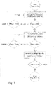
- the steps taken are in 2 shown schematically.
- the control and monitoring device 11 sends a signal to the heating device 10 to switch on the first group 12a of heating rods of the heating device 10 .
- This switching on alone increases the electrical load present on the generator 3 and, as a result, the load present on the diesel engine 2 .
- the speed control 9 controls the diesel engine 2 in such a way that it continues to run at a target speed of 1600 min -1 despite the increased load. The higher power required for this means that the operating temperature of the diesel engine 2 increases.
- the control and monitoring device 11 now monitors whether the load applied to the diesel engine 2 by switching on the first group 12a of heating rods of the heating device 10 or the current to be supplied by the generator 3 exceeds a threshold value (e.g. 20 A).
- a threshold value e.g. 20 A
- the control and monitoring device 11 can also monitor whether the operating temperature of the diesel engine 2 has reached the operating level necessary for burning off soot deposits within a certain period of time.
- control and monitoring device 11 emits a further control signal to the heating device 10 to switch on the second group 12b of heating rods.
- the speed of the electric drive motor 4 is further increased in the manner already described above.
- additional heating elements of the heating device 10 can optionally be switched on in order to increase the electrical energy requirement.
- the speed of the drive motor 4 must also be increased here in order to compensate for the increased heat input into the air flow VA through increased cooling capacity.
- the electrical load of the generator 3 and the corresponding drive load to be performed by the diesel engine 2 increase until an operating temperature level sufficient for burning off the soot deposits is reliably reached.
- the regeneration operation of the transport refrigeration machine 1 is maintained over a regeneration interval tREG of 15 minutes, for example.
- the control and monitoring device 11 then sends a control signal to switch off the heating device 10 and a new operating time interval begins, in which the transport refrigeration machine 1 is operated in normal cooling mode with the diesel engine 2 operating mode corresponding to the cooling capacity setpoint.
- the diesel engine 2 is regenerated in the opposite way when the transport refrigeration machine 1 is running in heating mode.
- the air flow VA is heated by means of the heating device 10 (here the first temperature control device), while the drive motor 4 stands still and no cooling capacity is delivered to the air flow VA via the heat exchanger 8.
- the drive motor 4 is then put into operation for the regeneration of the diesel engine 2 , so that the air flow VA flowing through the heat exchanger 8 (here the second temperature control device) is additionally cooled before it enters the heating device 10 .
- the heat output of the heating device 10 must be increased by switching on further groups 12a, 12b of heating rods.
- the transport refrigeration machine 101 shown comprises a diesel engine 102 designed like the diesel engine 2, a compressor 105, a first condenser 106, a throttle 107, a heat exchanger 108, a speed control device 109 and a control and monitoring device 111.
- the drive motor 102 is mechanically coupled directly to the compressor 105 by means of a belt drive 104 .
- the speed of the compressor 105 is therefore directly proportional to the speed of the diesel engine 102.
- a second condenser 113 two control valves 114, 115 and two check valves 116, 117 are provided in the transport refrigerating machine 101 as the second temperature control device.
- the refrigerant fluid line 118 leading away from the outlet 105a of the compressor 105 is divided into two branches 119, 120, of which the first control valve 114 is arranged in one branch and the second control valve 115 is arranged in the other branch.
- the control valves 114, 115 are each connected to a control output of the control and monitoring device 111.
- control valve 114 In normal operation ( Figure 3a ) control valve 114 is open and control valve 115 is closed.
- the refrigerant VK then flows through the first branch 119 of the refrigerant line 118 to the first condenser 106 and from there via the first check valve 116 and via the throttle to the primary side 108b of the heat exchanger 108.
- the second check valve 117 is closed and prevents the refrigerant VK from flowing out into the second branch 120 of the refrigerant fluid line 118.
- control valve 115 is open and control valve 114 is closed.
- the refrigerant VK flows through the second branch 120 of the refrigerant line 118 to the second condenser 113 and from there via the second check valve 117 and via the throttle to the primary side 108b of the heat exchanger 108.
- the first check valve 117 is closed and prevents the Refrigerant fluid VK in the first branch 119 of the refrigerant fluid line 118.
- the refrigerant VK flows back to the inlet 105b of the compressor 105.
- the second condenser 113 is seated as the second temperature control device in the flow path of the air flow VA, so that the air flow VA sweeps along the second condenser 113 before it enters the heat exchanger 108 .
- the control valve 114 closes in response to corresponding control signals from the control and monitoring device 111 and opens the control valve 115.
- Refrigerant fluid VK now flows through the second branch 120 of the refrigerant fluid line and condenses while releasing heat in the condenser 113.
- the airflow guided along the condenser 113 is correspondingly heated before it enters the heat exchanger 108 in order to be cooled there to a desired temperature.
- valve 114 is opened in order to conduct a partial flow of the cooling fluid via the first condenser 106 and the Branch 120 to relieve the cooling fluid line 118. If the pressure in branch 120 has fallen below a reference value again in this way, valve 114 is closed again until a pressure that approaches the permissible limit pressure has built up again in branch 120 of cooling fluid line 118, whereupon valve 114 is opened again .
- valve 114 as a function of the pressure in branch 120 of cooling fluid line 118 is continued until the end of the regeneration interval, so that the amount of heat given off by condenser 113 to air flow VA flowing against it is maximized despite the pressure limitation , which applies to the branch 120 of the cooling fluid line 118 and the units connected to it, through which the cooling fluid flows.
- valve 114 As an alternative or in addition to the control of valve 114 described here, which takes place as a function of the pressure in branch 120, the valve could be opened and closed as a function of time, with the opening and closing times being dimensioned in such a way that the pressure in branch 120 does not exceed cooling fluid line 118 the respective permissible limit increases. Since the power to be provided by the diesel engine 102 is proportional to the pressure in the branch 120, it would also be possible to monitor the power output at the drive motor 102 and to open the valve 114 if the power output exceeds a certain maximum value, or to close it if the power consumption falls below a certain minimum value.
- the diesel engine 102 After the regenerative operation has been maintained for a sufficiently long period of time, the diesel engine 102 will return to normal performance.
- the control device 111 now emits control signals again, upon which the control valve 114 opens and the control valve 115 closes in order to return to the normal cooling mode of the transport refrigeration machine 101 .
- the transport refrigeration machine 201 shown has a diesel engine 202 designed like diesel engine 2, a generator 203, an electrically operated drive motor 204, a compressor 205 driven by drive motor 204, a condenser 206, a throttle 207, a heat exchanger 208, a speed control device 209 and a control and Monitoring device 211.
- the diesel engine 202 drives the generator 203 , which generates electrical energy for driving the electric drive motor 204 .
- the speed control device 209 also keeps the diesel engine 202 at a constant operating speed of, for example, 1600 min -1 in an operating point that is optimal in terms of energy utilization.
- the heat exchanger 208 forms a first temperature control device of the transport refrigeration machine 201 and has a secondary side 208a, through which the air flow VA to be cooled, flowing out of the loading space, is conducted, and a primary side 208b, through which the cooling fluid volume flow VK flows. which flows via an inflow line from the compressor outlet 205a via the condenser 206 and the throttle 207 to the heat exchanger inlet.
- An air guiding device 214 is arranged upstream of the heat exchanger 208 in the direction of flow, the control input of which is connected to a control output of the control and monitoring device 211 .
- the air guiding device 214 directs the air flow VA to be cooled directly to the heat exchanger 208.
- control and monitoring device 211 If, on the other hand, control and monitoring device 211 establishes that diesel engine 202 has been operated for too long, for example, in an operating state that causes sooting, then control and monitoring device 211 emits an actuating signal to start regeneration operation, on which towards the air guiding device 214 redirects the air flow VA so that it flows through the water cooler 213 of the diesel engine 202 before it enters the heat exchanger 208 ( Figure 4b ).
- the water cooler 213 thus also represents a second temperature control device, through which the air flow VA is additionally heated before it is cooled in the heat exchanger 208, with the result that the heat exchanger 208 also has to apply an increased cooling capacity here in order to bring the air flow VA to its target temperature to cool down
- the speed of the compressor 205 and, as a result, the drive power of the drive motor 204 must be increased. This in turn results in an increased load on the generator 203 and, as a result, on the diesel engine 202 applied. As a result, the diesel engine 202 has to provide increased power, which leads to a desired increase in its operating temperature.
- the air flow VA can also be diverted during the regeneration interval in such a way that it sweeps over the entire diesel engine 202 and/or is routed along the exhaust system of the diesel engine 202, not shown here, in order to introduce additional heat into the air flow VA.
- control and monitoring device 211 emits a further control signal, upon which air guiding device 214 moves back into its normal position for normal operation, during which the air flow VA reaches the heat exchanger 208 directly, without being additionally temperature-controlled.
- the unit that forms the second temperature control device (condenser 113, water cooler 213) is arranged upstream of the first temperature control device (heat exchanger 108, 208) in the direction of flow of the air flow VA, so that the air flow VA heats up is before it enters the first temperature control device (heat exchanger 108, 208).
- the respective second temperature control device (condenser 113, water cooler 213) in these configurations could also be arranged behind the respective first temperature control device (heat exchanger 108, 208) in the direction of flow of the air flow VA with the same effect, i.e. cooling first of the air flow takes place and then heating, so that Here, too, additional cooling capacity must be introduced in order to achieve the target temperature of the hold atmosphere.
Landscapes
- Engineering & Computer Science (AREA)
- Chemical & Material Sciences (AREA)
- Combustion & Propulsion (AREA)
- Mechanical Engineering (AREA)
- General Engineering & Computer Science (AREA)
- Devices That Are Associated With Refrigeration Equipment (AREA)
Priority Applications (1)
| Application Number | Priority Date | Filing Date | Title |
|---|---|---|---|
| EP21162667.6A EP4060176A1 (fr) | 2021-03-15 | 2021-03-15 | Procédé de fonctionnement d'un réfrigérateur de transport |
Applications Claiming Priority (1)
| Application Number | Priority Date | Filing Date | Title |
|---|---|---|---|
| EP21162667.6A EP4060176A1 (fr) | 2021-03-15 | 2021-03-15 | Procédé de fonctionnement d'un réfrigérateur de transport |
Publications (1)
| Publication Number | Publication Date |
|---|---|
| EP4060176A1 true EP4060176A1 (fr) | 2022-09-21 |
Family
ID=74874763
Family Applications (1)
| Application Number | Title | Priority Date | Filing Date |
|---|---|---|---|
| EP21162667.6A Pending EP4060176A1 (fr) | 2021-03-15 | 2021-03-15 | Procédé de fonctionnement d'un réfrigérateur de transport |
Country Status (1)
| Country | Link |
|---|---|
| EP (1) | EP4060176A1 (fr) |
Citations (4)
| Publication number | Priority date | Publication date | Assignee | Title |
|---|---|---|---|---|
| DE102010022993A1 (de) | 2010-06-08 | 2011-12-08 | Schmitz Cargobull Ag | Transportkältemaschine zum Kühlen des Innenraums |
| WO2013134238A1 (fr) * | 2012-03-09 | 2013-09-12 | Carrier Corporation | Régénération de filtre pour diesel dans des systèmes de réfrigération de transport |
| US20160185187A1 (en) * | 2013-08-14 | 2016-06-30 | Carrier Corporation | Diesel engine powered transportation refrigeration system |
| WO2019036344A1 (fr) * | 2017-08-14 | 2019-02-21 | Carrier Corporation | Système de réfrigération de transport et procédé de régénération d'un filtre à particules diesel |
-
2021
- 2021-03-15 EP EP21162667.6A patent/EP4060176A1/fr active Pending
Patent Citations (4)
| Publication number | Priority date | Publication date | Assignee | Title |
|---|---|---|---|---|
| DE102010022993A1 (de) | 2010-06-08 | 2011-12-08 | Schmitz Cargobull Ag | Transportkältemaschine zum Kühlen des Innenraums |
| WO2013134238A1 (fr) * | 2012-03-09 | 2013-09-12 | Carrier Corporation | Régénération de filtre pour diesel dans des systèmes de réfrigération de transport |
| US20160185187A1 (en) * | 2013-08-14 | 2016-06-30 | Carrier Corporation | Diesel engine powered transportation refrigeration system |
| WO2019036344A1 (fr) * | 2017-08-14 | 2019-02-21 | Carrier Corporation | Système de réfrigération de transport et procédé de régénération d'un filtre à particules diesel |
Similar Documents
| Publication | Publication Date | Title |
|---|---|---|
| DE102013211700B3 (de) | Fahrzeugheizsystem sowie Verfahren zum Heizen des Innenraums eines Fahrzeugs mit einem Fahrzeugheizsystem | |
| DE102017201206A1 (de) | Abwärmenutzungseinrichtung für ein Elektrofahrzeug | |
| DE102017201202A1 (de) | Abwärmenutzungseinrichtung für ein Elektrofahrzeug | |
| DE102012223808B4 (de) | Brennkraftmaschine mit Abgasturboaufladung und Abgasrückführung und Verfahren zum Betreiben einer derartigen Brennkraftmaschine | |
| DE102010044026A1 (de) | Hybrid Kühlsystem eines Verbrennungsmotors | |
| DE102008028290A1 (de) | Einrichtung zur Kühlung eines Kühlmittels, Kreislauf zur Aufladung einer Brennkraftmaschine und Verfahren zum Kühlen eines zur Aufladung einer Brennkraftmaschine vorgesehenen im Wesentlichen gasförmigen Ladefluids | |
| DE10234608A1 (de) | Verfahren zum Betrieb eines Kühl- und Heizkreislaufs eines Kraftfahrzeugs | |
| DE102015216420B4 (de) | Kühlanordnung zur Ladeluftkühlung | |
| EP1961593A1 (fr) | Climatisation pour véhicule | |
| WO2001040638A2 (fr) | Dispositif d'alimentation en carburant pour moteur a combustion interne | |
| EP1472106B1 (fr) | Installation de climatisation ayant une fonction chauffage et son mode de fonctionnement | |
| EP2213859A2 (fr) | Procédé destiné au réglage d'un refroidisseur d'air de suralimentation | |
| EP3159506A1 (fr) | Synergies fonctionnelles lors de l'integration de systeme orc dans des moteurs a combustion interne | |
| EP3530899A1 (fr) | Système de refroidissement et moteur à combustion interne | |
| DE102018113687A1 (de) | Vorrichtung und Verfahren zur Kühlung von Batteriezellenmodulen | |
| EP3470287B1 (fr) | Dispositif de climatisation d'un véhicule ferroviaire | |
| WO2006066713A1 (fr) | Systeme et procede pour reguler la temperature d'une huile moteur dans un moteur a combustion interne d'un vehicule automobile | |
| EP0783658B1 (fr) | Procede et dispositif de refroidissement de gaz | |
| EP1348096B1 (fr) | Dispositif et procede de refroidissement | |
| DE102020107652A1 (de) | Verfahren zum Abtauen eines als Luftwärmepumpe betriebenen äußeren Wärmeübertragers einer Kälteanlage für ein Kraftfahrzeug, Kälteanlage und Kraftfahrzeug mit einer solchen Kälteanlage | |
| WO2006008221A1 (fr) | Procede d'utilisation d'un groupe de turbines a gaz | |
| EP4060176A1 (fr) | Procédé de fonctionnement d'un réfrigérateur de transport | |
| DE102013201787A1 (de) | Verfahren und Vorrichtung zur Wirkungsgradverbesserung im Antriebssystem eines Kraftfahrzeugs | |
| EP3470646B1 (fr) | Procédé de fonctionnement d'un moteur à combustion interne, moteur à combustion interne et véhicule automobile | |
| EP2245305B1 (fr) | Véhicule utilitaire présentant un compresseur refroidi et procédé pour refroidir un compresseur |
Legal Events
| Date | Code | Title | Description |
|---|---|---|---|
| PUAI | Public reference made under article 153(3) epc to a published international application that has entered the european phase |
Free format text: ORIGINAL CODE: 0009012 |
|
| STAA | Information on the status of an ep patent application or granted ep patent |
Free format text: STATUS: THE APPLICATION HAS BEEN PUBLISHED |
|
| AK | Designated contracting states |
Kind code of ref document: A1 Designated state(s): AL AT BE BG CH CY CZ DE DK EE ES FI FR GB GR HR HU IE IS IT LI LT LU LV MC MK MT NL NO PL PT RO RS SE SI SK SM TR |
|
| STAA | Information on the status of an ep patent application or granted ep patent |
Free format text: STATUS: REQUEST FOR EXAMINATION WAS MADE |
|
| 17P | Request for examination filed |
Effective date: 20230321 |
|
| RBV | Designated contracting states (corrected) |
Designated state(s): AL AT BE BG CH CY CZ DE DK EE ES FI FR GB GR HR HU IE IS IT LI LT LU LV MC MK MT NL NO PL PT RO RS SE SI SK SM TR |
|
| P01 | Opt-out of the competence of the unified patent court (upc) registered |
Effective date: 20230515 |
|
| STAA | Information on the status of an ep patent application or granted ep patent |
Free format text: STATUS: EXAMINATION IS IN PROGRESS |
|
| 17Q | First examination report despatched |
Effective date: 20241104 |