EP4060209B1 - Système de joint de carbone d'autoguidage - Google Patents
Système de joint de carbone d'autoguidage Download PDFInfo
- Publication number
- EP4060209B1 EP4060209B1 EP22157566.5A EP22157566A EP4060209B1 EP 4060209 B1 EP4060209 B1 EP 4060209B1 EP 22157566 A EP22157566 A EP 22157566A EP 4060209 B1 EP4060209 B1 EP 4060209B1
- Authority
- EP
- European Patent Office
- Prior art keywords
- seal
- seat
- face
- diameter surface
- outer diameter
- Prior art date
- Legal status (The legal status is an assumption and is not a legal conclusion. Google has not performed a legal analysis and makes no representation as to the accuracy of the status listed.)
- Active
Links
Images


Classifications
-
- F—MECHANICAL ENGINEERING; LIGHTING; HEATING; WEAPONS; BLASTING
- F16—ENGINEERING ELEMENTS AND UNITS; GENERAL MEASURES FOR PRODUCING AND MAINTAINING EFFECTIVE FUNCTIONING OF MACHINES OR INSTALLATIONS; THERMAL INSULATION IN GENERAL
- F16J—PISTONS; CYLINDERS; SEALINGS
- F16J15/00—Sealings
- F16J15/16—Sealings between relatively-moving surfaces
- F16J15/34—Sealings between relatively-moving surfaces with slip-ring pressed against a more or less radial face on one member
- F16J15/3464—Mounting of the seal
- F16J15/3472—Means for centering or aligning the contacting faces
-
- F—MECHANICAL ENGINEERING; LIGHTING; HEATING; WEAPONS; BLASTING
- F01—MACHINES OR ENGINES IN GENERAL; ENGINE PLANTS IN GENERAL; STEAM ENGINES
- F01D—NON-POSITIVE DISPLACEMENT MACHINES OR ENGINES, e.g. STEAM TURBINES
- F01D11/00—Preventing or minimising internal leakage of working-fluid, e.g. between stages
- F01D11/003—Preventing or minimising internal leakage of working-fluid, e.g. between stages by packing rings; Mechanical seals
-
- F—MECHANICAL ENGINEERING; LIGHTING; HEATING; WEAPONS; BLASTING
- F01—MACHINES OR ENGINES IN GENERAL; ENGINE PLANTS IN GENERAL; STEAM ENGINES
- F01D—NON-POSITIVE DISPLACEMENT MACHINES OR ENGINES, e.g. STEAM TURBINES
- F01D25/00—Component parts, details, or accessories, not provided for in, or of interest apart from, other groups
- F01D25/18—Lubricating arrangements
- F01D25/183—Sealing means
-
- F—MECHANICAL ENGINEERING; LIGHTING; HEATING; WEAPONS; BLASTING
- F02—COMBUSTION ENGINES; HOT-GAS OR COMBUSTION-PRODUCT ENGINE PLANTS
- F02C—GAS-TURBINE PLANTS; AIR INTAKES FOR JET-PROPULSION PLANTS; CONTROLLING FUEL SUPPLY IN AIR-BREATHING JET-PROPULSION PLANTS
- F02C7/00—Features, components parts, details or accessories, not provided for in, or of interest apart form groups F02C1/00 - F02C6/00; Air intakes for jet-propulsion plants
- F02C7/28—Arrangement of seals
-
- F—MECHANICAL ENGINEERING; LIGHTING; HEATING; WEAPONS; BLASTING
- F16—ENGINEERING ELEMENTS AND UNITS; GENERAL MEASURES FOR PRODUCING AND MAINTAINING EFFECTIVE FUNCTIONING OF MACHINES OR INSTALLATIONS; THERMAL INSULATION IN GENERAL
- F16J—PISTONS; CYLINDERS; SEALINGS
- F16J15/00—Sealings
- F16J15/16—Sealings between relatively-moving surfaces
- F16J15/34—Sealings between relatively-moving surfaces with slip-ring pressed against a more or less radial face on one member
- F16J15/3436—Pressing means
- F16J15/344—Pressing means the pressing force being applied by means of an elastic ring supporting the slip-ring
-
- F—MECHANICAL ENGINEERING; LIGHTING; HEATING; WEAPONS; BLASTING
- F16—ENGINEERING ELEMENTS AND UNITS; GENERAL MEASURES FOR PRODUCING AND MAINTAINING EFFECTIVE FUNCTIONING OF MACHINES OR INSTALLATIONS; THERMAL INSULATION IN GENERAL
- F16J—PISTONS; CYLINDERS; SEALINGS
- F16J15/00—Sealings
- F16J15/16—Sealings between relatively-moving surfaces
- F16J15/34—Sealings between relatively-moving surfaces with slip-ring pressed against a more or less radial face on one member
- F16J15/3436—Pressing means
- F16J15/3452—Pressing means the pressing force resulting from the action of a spring
-
- F—MECHANICAL ENGINEERING; LIGHTING; HEATING; WEAPONS; BLASTING
- F05—INDEXING SCHEMES RELATING TO ENGINES OR PUMPS IN VARIOUS SUBCLASSES OF CLASSES F01-F04
- F05D—INDEXING SCHEME FOR ASPECTS RELATING TO NON-POSITIVE-DISPLACEMENT MACHINES OR ENGINES, GAS-TURBINES OR JET-PROPULSION PLANTS
- F05D2240/00—Components
- F05D2240/55—Seals
-
- F—MECHANICAL ENGINEERING; LIGHTING; HEATING; WEAPONS; BLASTING
- F05—INDEXING SCHEMES RELATING TO ENGINES OR PUMPS IN VARIOUS SUBCLASSES OF CLASSES F01-F04
- F05D—INDEXING SCHEME FOR ASPECTS RELATING TO NON-POSITIVE-DISPLACEMENT MACHINES OR ENGINES, GAS-TURBINES OR JET-PROPULSION PLANTS
- F05D2260/00—Function
- F05D2260/30—Retaining components in desired mutual position
- F05D2260/38—Retaining components in desired mutual position by a spring, i.e. spring loaded or biased towards a certain position
-
- F—MECHANICAL ENGINEERING; LIGHTING; HEATING; WEAPONS; BLASTING
- F16—ENGINEERING ELEMENTS AND UNITS; GENERAL MEASURES FOR PRODUCING AND MAINTAINING EFFECTIVE FUNCTIONING OF MACHINES OR INSTALLATIONS; THERMAL INSULATION IN GENERAL
- F16J—PISTONS; CYLINDERS; SEALINGS
- F16J15/00—Sealings
- F16J15/16—Sealings between relatively-moving surfaces
- F16J15/34—Sealings between relatively-moving surfaces with slip-ring pressed against a more or less radial face on one member
- F16J15/3436—Pressing means
- F16J15/3448—Pressing means the pressing force resulting from fluid pressure
Definitions
- Carbon seals are commonly used to seal between relatively rotating components in gas turbine engines (used in propulsion and power applications and broadly inclusive of turbojets, turboprops, turbofans, turboshafts, industrial gas turbines, and the like). These include shaft seals (i.e., where the sealing surfaces of seal and seat face radially (e.g., within 1.0° or essentially 0°) and extend axially) and face seals (i.e., where the sealing surfaces face axially (e.g., within 1.0° or essentially 0°) and extend radially). In typical face seal situations, the annular carbon seal is axially spring biased into engagement with an annular seat (typically metallic such as a steel).
- an annular seat typically metallic such as a steel
- the carbon seal is on non-rotating static structure and the seat rotates with one of the engine shafts.
- the sliding engagement causes frictional heating.
- the heat must be dissipated.
- oil cooling With a rotating seat, it is common to use oil cooling.
- oil cooled carbon seals are divided into two categories: “dry face” seals wherein the oil passes through passageways in the seat without encountering the interface between seal face and seat face; and “wet face” seals wherein the oil passes through the seat to the interface so that the oil that flows through the seat cools the seat but then lubricates the interface to further reduce heat generation.
- EP 3,376,078 discloses an apparatus according to the preamble of claim 1 and comprising a mechanical seal suitable for a shaft sealing component.
- the section has a chamfer surface between the outer diameter surface and the rim.
- the chamfer surface has a half angle of 10° to 45° over at least one of: a radial span R S4 of at least 0.50% of a maximum radius of the seat section; and a length S A3 of at least 0.25 mm.
- the seat is steel.
- the seal and seat are full annular and the seal is interference fit in a seal carrier.
- the bellows spring is captured between a spring carrier and a seal carrier; and the seal carrier carries the seal.
- the seal carrier has an outer diameter sleeve section in interference fit with the seal.
- a method for assembling the apparatus comprises: mounting the seal to the first member so as to be cantilever supported by a bellows spring; and installing the seat so that the section passes radially within the seal.
- the contact is effective to prevent axial separation between the seal and the seat.
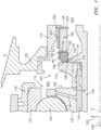
- FIG. 1 shows a seal system 100 having a seal 102 and a seat 104.
- the seal system is used in a turbomachine such as a gas turbine engine for a purpose such as isolating a bearing compartment 600.
- the seal is mounted to a first structure such as an engine static structure and the seat is mounted to rotate relative thereto (e.g., mounted to a shaft) about an axis A which may be the engine centerline or central longitudinal axis.
- the example seal 102 is a carbon seal having an axially-facing/radially-extending seal surface or face 106.
- the example seal 102 is formed as single-piece or segmented body of revolution about an axis normally coincident with the centerline A.
- a constraint on the relative radial freedom of movement is imposed to limit the relative radial displacement. For example, it may be limited to less than the extent at which axial displacement initiates. In FIG. 2 , this displacement is associated with speed v 2 .
- the example bearing 110 is a rolling element bearing have an inner diameter (ID) race 130 (inner race), an outer diameter (OD) race 132 (outer race), and a circumferential array of rolling elements 134 (e.g., balls).
- the bearing may be lubricated (e.g., via passages 136 delivering oil from an oil system (not shown)) so that the bearing compartment 600 contains oil.
- the seal system 100 may serve to contain the oil in the bearing compartment to prevent leakage out.
- the outer race 132 is carried by a bearing support 140 which, in turn, is carried by the case component 120.
- the example seal system 100 includes a seal housing 170 for mounting to the remaining static structure of the engine.
- the seal 102 is mounted in a seal carrier 180 (e.g., a single-piece alloy machining) having an outer diameter collar/sleeve section 182 and a radial flange 184.
- the aft portion of the seal OD face and an OD portion of the seal aft face respectively contact an ID face of the sleeve 182 and a forward face of the flange 184.
- One or more springs 190 e.g., a single bellows spring shown schematically encircling the centerline A) axially bias the seal 102 into engagement with the seat 104.
- the spring 190 extends between a forward end 192 and an aft end 194.
- the spring is carried by a spring carrier 200 (e.g., a single-piece alloy machining) which, in turn, is mounted to the housing 170.
- the spring carrier 200 has an outer diameter (OD) collar/sleeve section 202 and a flange 204.
- the spring aft end abuts and is secured to the forward face of the flange 204 and the spring forward end 192 abuts and is secured to the aft face of the flange 184.
- the undercut 232 isolates the protruding section 210 from contact stresses in the seat caused by the compressive engagement of the surfaces 150 and 152.
- the example undercut 232 is axial-only; whereas the undercut 222 is axial/radial.
- FIG. 1A also shows the sleeve 182 as having a forward rim 240 axially recessed relative to the seal face 106. This recessing accommodates seal wear and reduces with use. A recess/rebate 227 in the seal's OD surface 228 ahead of the rim 240 limits contact stresses in the seal at the ID forward corner 241 of the sleeve cross-section. This is particularly relevant where the seal is in radial interference fit with the sleeve.
- Example S A3 is at least 10% of S A2 , more particularly, 25% to 50%.
- S A2 may be 1.25 mm to 12.7 mm, more particularly 1.25 mm to 5.0 mm.
- S A3 may be at least 0.25 mm, more particularly 0.25 mm to 2.50, more particularly 0.50 mm to 1.0 mm.
- the example angle of the chamfer (a half angle ⁇ of the cone of chamfering) is 10° to 45°, more particularly, 25° to 40° or 20° to 30°.
- FIG. 1A shows a radial span from the radial inboard/distal end of the chamfer 218 to the seal ID face 216 as R S3 (when concentric).
- R S1 is selected based upon limiting dynamic excursions.
- R S3 is chosen to make the ID of the chamfer effective to partially center the seal 102 relative to the seat during assembly to address sag in the seal.
- R S3 may be 0.75% to 3.50% of the radius R OF from the centerline A to the OD surface portion 216, more particularly 1.50% to 2.50%. As noted above for R S1 , this may scale substantially upward for smaller scale applications.
- FIG. 1A shows a radial span of the chamfer 218 as R S4 .
- R S4 may be 0.050% to 20% of the radius R OF from the centerline A to the OD surface portion 216, more particularly 0.050% to 1.0% (particularly for larger applications).
- FIG. 3 shows an alternative implementation wherein the chamfer and the radial stop surface are on a spacer piece 400 separate from a main seat piece 402.
- the illustrated example is the same as FIG. 1 .
- the example bellows spring is formed of steel (e.g., stainless) and may be assembled by welding individual essentially frustoconical sections to each other. remaining components may be machined. In an example of an assembly procedure, the spring ends are welded to the associated flanges of the spring carrier and seal carrier respectively.
- the seal is installed to the seal carrier such as via thermal interference fit (e.g., heating the seal carrier to radial expand and then axially inserting a single-annulus or segmented annulus seal and allowing the seal carrier to cool into radial interference).
- This seal assembly may then, similarly, be installed to the housing 170.
- An example installation involves a combination of thermal interference and anti-rotation keying.
- the housing 170 may be heated and the seal assembly linearly inserted and held in place while the housing is allowed to cool.
- Example anti-rotation /keying features include: slot and key features; bolted flange features; and slot and groove with retention wire.
- a bolted flange may replace the interference fit.
- a further subassembly comprising the bearing, seat, spacer (if present) and gear may be assembled.
- the bearing, seat, spacer 400 (if present) are heated at their respective inner diameters (e.g., via torch) and installed onto gear sleeve 144 by linear translation while each remain hot.
- An axial load may be placed on them and maintained (e.g., until temperatures return to room temperature or within a sufficient margin to provide the thermal interference fit).
- the bearing-seat-gear subassembly is then heated (e.g., via torch) at the inner diameter of gear sleeve and the support 140 is heated (e.g., via torch) at an ID surface that mates with the bearing outer race.
- the bearing-seat-gear subassembly may then be installed to the shaft piece 146 and support 140 (e.g., by linear translation). During this installation, the chamfer 218 will pass within the seal 102. As the chamfer approaches the seal, the seal, seal carrier, and bellows spring are cantilevered from the spring carrier. In a horizontal assembly situation, there will be a gravity-induced sag so that there is contact of the chamfer and seal front ID edge at 12 o'clock.
- the chamfer will guide the seal onto the main axial portion 220 from where the seal face passes into engagement with the seat face. Absent the chamfer, the rim 212 might collide with and either be stopped by or damage the seal. An axial load applied to the subassembly compresses the bellows spring and is maintained (e.g., until temperatures return to room temperature or within a sufficient margin to provide the thermal interference fit). This leaves the bellows spring precompressed.
- bellows springs provide sealing.
- Other springs e.g., a circumferential array of coil springs
- Such secondary sealing elements may damp vibration and thereby reduce the resonant coupling relative to a bellows seal of similar spring constant/compression.
- the axial span S A1 may be selected to be sufficiently long to provide sufficient distribution of radial contact force to limit seal ID wear from excursions that are stopped.
- S A3 is selected to provide the desired radial span R S3 in view of R S1 and the desired angle ⁇ .
- S A4 reflects the combination of these axial spans plus the desired axial span of the relief 222.
- the axial span S A4 may be limited in some embodiments by potential obstructions such as a seal carrier that has an ID sleeve similar to the OD sleeve 182 and/or a seal with an ID rebate similar to OD rebate 227.
- flange axial span S A4 may accommodate the allowable wear length of the seal.
- the allowable wear length is inherently limited by the length S A6 ( FIG. 1A ) of the recessing of the seal carrier rim 240 relative to the seal face 106.
- S A4 may be 0.10% to 80% of the radius R OF from the centerline A to the OD surface portion 216, more particularly 0.10% to 10% or 0.25 mm to 5.0 mm.
- S A1 may be selected to be sufficiently long to axially distribute forces during contact with the seal ID surface 226.
- S A1 may be 0.10% to 80% of the radius R OF from the centerline A to the OD surface portion 216, more particularly 0.10% to 10% (as a rough value this is given as the same as S A4 despite the presence of the relief 222).
- FIG. 4 schematically illustrates a gas turbine engine 20 as one of many examples of an engine in which the seal system 100 may be used.
- the gas turbine engine 20 is disclosed herein as a two-spool turbofan that generally incorporates a fan section 22, a compressor section 24, a combustor section 26 and a turbine section 28.
- the fan section 22 may include a single-stage fan 42 having a plurality of fan blades 43.
- the fan blades 43 may have a fixed stagger angle or may have a variable pitch to direct incoming airflow from an engine inlet.
- the fan 42 drives air along a bypass flow path B in a bypass duct 13 defined within a housing 15 such as a fan case or nacelle, and also drives air along a core flow path C for compression and communication into the combustor section 26 then expansion through the turbine section 28.
- a splitter 29 aft of the fan 42 divides the air between the bypass flow path B and the core flow path C.
- the housing 15 may surround the fan 42 to establish an outer diameter of the bypass duct 13.
- the splitter 29 may establish an inner diameter of the bypass duct 13.
- the low speed spool 30 generally includes an inner shaft 40 that interconnects, a first (or low) pressure compressor 44 and a first (or low) pressure turbine 46.
- the inner shaft 40 is connected to the fan 42 through a speed change mechanism, which in the example gas turbine engine 20 is illustrated as a geared architecture 48 to drive the fan 42 at a lower speed than the low speed spool 30.
- the inner shaft 40 may interconnect the low pressure compressor (LPC) 44 and low pressure turbine (LPT) 46 such that the low pressure compressor 44 and low pressure turbine 46 are rotatable at a common speed and in a common direction.
- the low pressure turbine 46 drives both the fan 42 and low pressure compressor 44 through the geared architecture 48 such that the fan 42 and low pressure compressor 44 are rotatable at a common speed.
- the high speed spool 32 includes an outer shaft 50 that interconnects a second (or high) pressure compressor (HPC) 52 and a second (or high) pressure turbine (HPT) 54.
- a combustor 56 is arranged in the example gas turbine 20 between the high pressure compressor 52 and the high pressure turbine 54.
- a mid-turbine frame 57 of the engine static structure 36 may be arranged generally between the high pressure turbine 54 and the low pressure turbine 46.
- the mid-turbine frame 57 further supports bearing systems 38 in the turbine section 28.
- the inner shaft 40 and the outer shaft 50 are concentric and rotate via bearing systems 38 about the engine central longitudinal axis A which is collinear with their longitudinal axes.
- first, second, and the like in the following claims is for differentiation within the claim only and does not necessarily indicate relative or absolute importance or temporal order. Similarly, the identification in a claim of one element as “first” (or the like) does not preclude such "first” element from identifying an element that is referred to as “second” (or the like) in another claim or in the description.
Landscapes
- Engineering & Computer Science (AREA)
- General Engineering & Computer Science (AREA)
- Mechanical Engineering (AREA)
- Chemical & Material Sciences (AREA)
- Combustion & Propulsion (AREA)
- Mechanical Sealing (AREA)
Claims (14)
- Appareil, par exemple, moteur à turbine à gaz (20), comprenant :un premier élément (36) ;un arbre (40, 50) pouvant tourner par rapport au premier élément (36) autour d'un axe (A) ; etun système de joint (100) comprenant :un joint (102) porté par le premier élément (36) et présentant une face de joint (106) ; etun siège (104) porté par l'arbre (40, 50) et présentant une face de siège (108) en engagement d'étanchéité coulissant avec la face de joint (106) ;dans lequel :le système de joint (100) est un système de joint à face sèche ;le siège (104) comprend également une section de siège (210) présentant :une surface de diamètre extérieur (216) présentant une partie axiale principale (220) entourée par le joint (102) ; etun rebord (212) ;un espace radial (230) est présent entre le joint (102) et la surface de diamètre extérieur (216) de la section de siège (210), l'espace (230) présentant une portée radiale minimale constante (RS1) le long de la partie axiale principale (220) de la surface de diamètre extérieur (216), caractérisé en ce qu'un ressort à soufflet (190) sollicite axialement le joint (102) en prise avec le siège (104),dans lequel, lors de l'utilisation, une surface de diamètre intérieur (226) du joint est configurée pour entrer en contact avec la surface de diamètre extérieur de la section de siège (216) ; etla portée radiale (RS1) de l'espace radial (230) est dimensionnée pour limiter le déplacement dynamique radial relatif du siège (104) et du joint (102).
- Appareil selon la revendication 1, dans lequel l'espace radial (230) entre la surface de diamètre extérieur (216) et le joint (102) est formé entre :la partie de surface de diamètre intérieur (226) du joint (102) ; etla partie axiale principale (220) de la surface de diamètre extérieur (216) de ladite section de siège (210) présentant un rayon (ROF) variant d'au plus 0,12 % sur une longueur (SA1) de 25 % à 50 % d'une portée axiale (SA2) depuis la face de siège (108) jusqu'au rebord (212).
- Appareil selon la revendication 1 ou 2, dans lequel la section de siège (210) est située le long d'une bride en saillie présentant :une surface de diamètre interne (214) ; etune contre-dépouille axiale (232) à la racine de la section de siège (210).
- Appareil selon une quelconque revendication précédente dans lequel la section de siège (210) présente :
une surface de chanfrein (218) entre la surface de diamètre extérieur (216) et le rebord (212), dans lequel, éventuellement, la surface de chanfrein (216) présente un demi-angle de 10° à 45° sur au moins l'un des éléments suivants :une portée radiale (RS4) d'au moins 0,50 % de a ou du rayon (ROF) de la surface de diamètre extérieur (216) de la section de siège (210) ; etune longueur (SA3) d'au moins 0,25 mm. - Appareil selon une quelconque revendication précédente, dans lequel :
la face de siège (108) et la section de siège (210) sont constituées d'une seule pièce unitaire. - Appareil selon l'une quelconque des revendications 1 à 4, dans lequel :
la face de siège (108) est sur une première pièce et la section de siège (210) est formée sur une seconde pièce, dans lequel, éventuellement, la première pièce présente :une face de contact en contact avec une face de la seconde pièce ; etun canal entre la face de siège (108) et la face de contact. - Appareil selon une quelconque revendication précédente, dans lequel :le joint (102) est un joint de carbone ; et/oule siège (104) est en acier.
- Appareil selon une quelconque revendication précédente, dans lequel :le joint (102) et le siège (104) sont entièrement annulaires ; etle joint (102) est ajusté par serrage dans un support de joint (180) .
- Appareil selon une quelconque revendication précédente, dans lequel :le ressort à soufflet (190) est capturé entre un support de ressort (200) et un support de joint (180) ; etle support de joint (180) porte le joint (102).
- Appareil selon la revendication 8 ou 9, dans lequel :
le support de joint (180) présente une section de manchon de diamètre extérieur (182) en ajustement serré avec le joint (102). - Procédé d'assemblage de l'appareil selon une quelconque revendication précédente, le procédé comprenant :le montage du joint (102) sur le premier élément (36) de manière à ce qu'il soit supporté en porte-à-faux par le ressort à soufflet (190) ; etl'installation du siège (104) de manière à ce que la section de siège (210) passe radialement à l'intérieur du joint (102).
- Procédé selon la revendication 11, dans lequel :la section de siège (210) présente une surface de chanfrein (218) entre la surface de diamètre extérieur (216) et le rebord (212) ; etl'installation amène la surface de chanfrein (218) à entrer en contact avec le joint (102) et à déplacer radialement le joint (102) .
- Procédé d'utilisation de l'appareil selon l'une quelconque des revendications 1 à 10, le procédé comprenant :la rotation de l'arbre (40, 50) par rapport au premier élément (36) autour de l'axe (A) ; etune excursion radiale dynamique de l'arbre (40, 50) par rapport au premier élément (36) provoquant ledit contact entre la surface de diamètre extérieur (216) de la section de siège et une surface de diamètre intérieur (226) du joint.
- Procédé selon la revendication 13, dans lequel :
le contact est efficace pour empêcher la séparation axiale entre le joint (102) et le siège (104).
Applications Claiming Priority (1)
| Application Number | Priority Date | Filing Date | Title |
|---|---|---|---|
| US17/206,521 US11608751B2 (en) | 2021-03-19 | 2021-03-19 | Self-guiding carbon seal system |
Publications (2)
| Publication Number | Publication Date |
|---|---|
| EP4060209A1 EP4060209A1 (fr) | 2022-09-21 |
| EP4060209B1 true EP4060209B1 (fr) | 2025-04-09 |
Family
ID=80775402
Family Applications (1)
| Application Number | Title | Priority Date | Filing Date |
|---|---|---|---|
| EP22157566.5A Active EP4060209B1 (fr) | 2021-03-19 | 2022-02-18 | Système de joint de carbone d'autoguidage |
Country Status (2)
| Country | Link |
|---|---|
| US (3) | US11608751B2 (fr) |
| EP (1) | EP4060209B1 (fr) |
Families Citing this family (1)
| Publication number | Priority date | Publication date | Assignee | Title |
|---|---|---|---|---|
| US12448904B1 (en) * | 2024-09-27 | 2025-10-21 | Pratt & Whitney Canada Corp. | Seal assembly mating plate for aircraft powerplant |
Family Cites Families (35)
| Publication number | Priority date | Publication date | Assignee | Title |
|---|---|---|---|---|
| US2990202A (en) * | 1958-09-18 | 1961-06-27 | United Aircraft Corp | Labyrinth face seal plate |
| US3276780A (en) | 1963-12-19 | 1966-10-04 | Gits Bros Mfg Co | Vibration control for bellows seal |
| US3765689A (en) | 1971-09-27 | 1973-10-16 | Durametallic Corp | Mechanical seal construction |
| US4261581A (en) | 1980-04-14 | 1981-04-14 | Durametallic Corporation | Mechanical seal with improved face ring mounting |
| US4406459A (en) * | 1982-06-18 | 1983-09-27 | United Technologies Corporation | Oil weepage return for carbon seal plates |
| US4406460A (en) | 1982-11-01 | 1983-09-27 | United Technologies Corporation | Anti-weepage valve for rotating seals |
| US4928978A (en) | 1988-04-07 | 1990-05-29 | United Technologies Corporation | Rotating shaft seal |
| US5160149A (en) | 1991-06-21 | 1992-11-03 | Allied-Signal Inc. | Seal rotor mount |
| JP3555683B2 (ja) | 1992-08-11 | 2004-08-18 | ユナイテッド・テクノロジーズ・コーポレイション | 回転機用シールアセンブリ |
| US6196790B1 (en) * | 1998-12-17 | 2001-03-06 | United Technologies Corporation | Seal assembly for an intershaft seal in a gas turbine engine |
| US7837199B2 (en) * | 2005-11-03 | 2010-11-23 | United Technologies Corporation | Shrouded face seal and components thereof |
| CA2746726C (fr) | 2008-12-12 | 2015-03-10 | Flowserve Management Company | Joint de pompe |
| US8714558B2 (en) | 2010-09-30 | 2014-05-06 | Eaton Corporation | Welded bellows seal assembly |
| US9309775B2 (en) | 2012-05-21 | 2016-04-12 | United Technologies Corporation | Rotational debris discourager for gas turbine engine bearing |
| US9546560B2 (en) * | 2012-09-11 | 2017-01-17 | United Technologies Corporation | Compact double grounded mechanical carbon seal |
| US20150240950A1 (en) * | 2012-10-19 | 2015-08-27 | EagleBurgmann Japan Co., Ltd. | Bellows Seal |
| US10233762B2 (en) * | 2013-02-27 | 2019-03-19 | United Technologies Corporation | Cooled seal assembly for arranging between a stator and a rotor |
| JP6219367B2 (ja) * | 2013-03-14 | 2017-10-25 | イーグルブルグマンジャパン株式会社 | メカニカルシール装置 |
| US10344679B2 (en) * | 2013-03-15 | 2019-07-09 | United Technologies Corporation | Shield for arranging between a bearing and a rotating seal element |
| EP2997258A1 (fr) * | 2013-05-14 | 2016-03-23 | Carrier Corporation | Joint d'arbre de compresseur de fluide frigorigène |
| US10030528B2 (en) * | 2014-01-08 | 2018-07-24 | United Technologies Corporation | Flanged spring guide for a face seal arrangement |
| WO2016118140A1 (fr) | 2015-01-22 | 2016-07-28 | Schlumberger Canada Limited | Joint d'étanchéité à face mécanique avec siège adaptable pour composants d'une pompe submersible électrique |
| JP6823602B2 (ja) | 2015-11-09 | 2021-02-03 | イーグル工業株式会社 | メカニカルシール |
| US10669873B2 (en) * | 2017-04-06 | 2020-06-02 | Raytheon Technologies Corporation | Insulated seal seat |
| US10788131B2 (en) * | 2017-08-01 | 2020-09-29 | Raytheon Technologies Corporation | Face seal arrangement |
| US20190178381A1 (en) * | 2017-12-13 | 2019-06-13 | United Technologies Corporation | Face seal arrangement with air load force balance recovery for improved failure mitigation strategies |
| US11209086B2 (en) * | 2018-10-29 | 2021-12-28 | Raytheon Technologies Corporation | Wet-face/dry-face seal and methods of operation |
| US11085540B2 (en) * | 2018-11-30 | 2021-08-10 | Rolls-Royce Corporation | Circumferential air riding carbon seal on ceramic runner |
| US10975723B2 (en) * | 2019-02-26 | 2021-04-13 | Raytheon Technologies Corporation | Gas turbine engine including seal plate providing increased cooling adjacent contact area |
| US11131388B2 (en) * | 2019-06-21 | 2021-09-28 | Raytheon Technologies Corporation | Seal assembly seal land with a gas flow passage |
| US11313471B2 (en) | 2020-05-05 | 2022-04-26 | Raytheon Technologies Corporation | Shrouded aircraft engine seal carrier |
| US11371374B2 (en) * | 2020-07-22 | 2022-06-28 | Raytheon Technologies Corporation | Seal runner flow damper |
| US11846355B2 (en) | 2020-10-16 | 2023-12-19 | Rtx Corporation | Dual windage blocker and retention feature design for seal assembly |
| US11434828B2 (en) | 2020-11-25 | 2022-09-06 | Raytheon Technologies Corporation | Face seal arrangement for reduced force and pressure |
| US11401832B2 (en) | 2021-01-05 | 2022-08-02 | Raytheon Technologies Corporation | Gas turbine engine including seal plate with separable tabs |
-
2021
- 2021-03-19 US US17/206,521 patent/US11608751B2/en active Active
-
2022
- 2022-02-18 EP EP22157566.5A patent/EP4060209B1/fr active Active
-
2023
- 2023-02-21 US US18/112,094 patent/US12163432B2/en active Active
- 2023-02-21 US US18/112,097 patent/US12180842B2/en active Active
Also Published As
| Publication number | Publication date |
|---|---|
| US20220298921A1 (en) | 2022-09-22 |
| EP4060209A1 (fr) | 2022-09-21 |
| US12163432B2 (en) | 2024-12-10 |
| US11608751B2 (en) | 2023-03-21 |
| US12180842B2 (en) | 2024-12-31 |
| US20230383668A1 (en) | 2023-11-30 |
| US20230407756A1 (en) | 2023-12-21 |
Similar Documents
| Publication | Publication Date | Title |
|---|---|---|
| EP3719265B1 (fr) | Joint de segment de piston rotatif en carbone | |
| EP3693552B1 (fr) | Ensemble de transfert de fluide pour turbine à gaz | |
| EP4105523B1 (fr) | Joint facial en carbone à ressort hélicoïdal | |
| EP2570612A1 (fr) | Assemblage de joints secondaires de turbomachine | |
| US12025010B2 (en) | Pressure-balanced carbon seal | |
| US7435052B2 (en) | Shaft oil purge system | |
| EP3690193B1 (fr) | Joint d'étanchéité et methode de fabrication d'un dispositif d'étanchéité | |
| US12163432B2 (en) | Self-guiding carbon seal system | |
| EP4191027B1 (fr) | Joint d'étanchéité à face en carbone | |
| EP3907377B1 (fr) | Système d'étanchéité à jeu radial réduit | |
| EP4215780B1 (fr) | Joint d'étanchéité à face en carbone | |
| EP3865659B1 (fr) | Adaptateur de sonde et son procédé d'utilisation | |
| US12276339B2 (en) | Carbon face seal | |
| EP3907376A1 (fr) | Porte-joint de moteur d'aéronef caréné | |
| EP4202263A1 (fr) | Élément d'étanchéité lié à un support d'étanchéité pour un moteur à turbine | |
| US20250035005A1 (en) | Seal assembly having at least one damping element | |
| US20250389200A1 (en) | Center Tie Rotor Annular Seal | |
| US20160298472A1 (en) | Shim to maintain gap during engine assembly | |
| EP3309364A2 (fr) | Système d'un moteur et dispositif associé |
Legal Events
| Date | Code | Title | Description |
|---|---|---|---|
| PUAI | Public reference made under article 153(3) epc to a published international application that has entered the european phase |
Free format text: ORIGINAL CODE: 0009012 |
|
| STAA | Information on the status of an ep patent application or granted ep patent |
Free format text: STATUS: THE APPLICATION HAS BEEN PUBLISHED |
|
| AK | Designated contracting states |
Kind code of ref document: A1 Designated state(s): AL AT BE BG CH CY CZ DE DK EE ES FI FR GB GR HR HU IE IS IT LI LT LU LV MC MK MT NL NO PL PT RO RS SE SI SK SM TR |
|
| STAA | Information on the status of an ep patent application or granted ep patent |
Free format text: STATUS: REQUEST FOR EXAMINATION WAS MADE |
|
| 17P | Request for examination filed |
Effective date: 20230321 |
|
| RBV | Designated contracting states (corrected) |
Designated state(s): AL AT BE BG CH CY CZ DE DK EE ES FI FR GB GR HR HU IE IS IT LI LT LU LV MC MK MT NL NO PL PT RO RS SE SI SK SM TR |
|
| RAP3 | Party data changed (applicant data changed or rights of an application transferred) |
Owner name: RTX CORPORATION |
|
| STAA | Information on the status of an ep patent application or granted ep patent |
Free format text: STATUS: EXAMINATION IS IN PROGRESS |
|
| 17Q | First examination report despatched |
Effective date: 20231117 |
|
| REG | Reference to a national code |
Ref country code: DE Ref legal event code: R079 Free format text: PREVIOUS MAIN CLASS: F16J0015340000 Ipc: F01D0025180000 Ref country code: DE Ref legal event code: R079 Ref document number: 602022012752 Country of ref document: DE Free format text: PREVIOUS MAIN CLASS: F16J0015340000 Ipc: F01D0025180000 |
|
| GRAP | Despatch of communication of intention to grant a patent |
Free format text: ORIGINAL CODE: EPIDOSNIGR1 |
|
| STAA | Information on the status of an ep patent application or granted ep patent |
Free format text: STATUS: GRANT OF PATENT IS INTENDED |
|
| INTG | Intention to grant announced |
Effective date: 20241028 |
|
| RIC1 | Information provided on ipc code assigned before grant |
Ipc: F01D 11/00 20060101ALI20241018BHEP Ipc: F16J 15/34 20060101ALI20241018BHEP Ipc: F01D 25/18 20060101AFI20241018BHEP |
|
| GRAS | Grant fee paid |
Free format text: ORIGINAL CODE: EPIDOSNIGR3 |
|
| GRAA | (expected) grant |
Free format text: ORIGINAL CODE: 0009210 |
|
| STAA | Information on the status of an ep patent application or granted ep patent |
Free format text: STATUS: THE PATENT HAS BEEN GRANTED |
|
| AK | Designated contracting states |
Kind code of ref document: B1 Designated state(s): AL AT BE BG CH CY CZ DE DK EE ES FI FR GB GR HR HU IE IS IT LI LT LU LV MC MK MT NL NO PL PT RO RS SE SI SK SM TR |
|
| REG | Reference to a national code |
Ref country code: GB Ref legal event code: FG4D |
|
| REG | Reference to a national code |
Ref country code: CH Ref legal event code: EP |
|
| REG | Reference to a national code |
Ref country code: DE Ref legal event code: R096 Ref document number: 602022012752 Country of ref document: DE |
|
| REG | Reference to a national code |
Ref country code: IE Ref legal event code: FG4D |
|
| REG | Reference to a national code |
Ref country code: NL Ref legal event code: MP Effective date: 20250409 |
|
| PG25 | Lapsed in a contracting state [announced via postgrant information from national office to epo] |
Ref country code: NL Free format text: LAPSE BECAUSE OF FAILURE TO SUBMIT A TRANSLATION OF THE DESCRIPTION OR TO PAY THE FEE WITHIN THE PRESCRIBED TIME-LIMIT Effective date: 20250409 |
|
| REG | Reference to a national code |
Ref country code: AT Ref legal event code: MK05 Ref document number: 1783672 Country of ref document: AT Kind code of ref document: T Effective date: 20250409 |
|
| PG25 | Lapsed in a contracting state [announced via postgrant information from national office to epo] |
Ref country code: FI Free format text: LAPSE BECAUSE OF FAILURE TO SUBMIT A TRANSLATION OF THE DESCRIPTION OR TO PAY THE FEE WITHIN THE PRESCRIBED TIME-LIMIT Effective date: 20250409 Ref country code: ES Free format text: LAPSE BECAUSE OF FAILURE TO SUBMIT A TRANSLATION OF THE DESCRIPTION OR TO PAY THE FEE WITHIN THE PRESCRIBED TIME-LIMIT Effective date: 20250409 Ref country code: PT Free format text: LAPSE BECAUSE OF FAILURE TO SUBMIT A TRANSLATION OF THE DESCRIPTION OR TO PAY THE FEE WITHIN THE PRESCRIBED TIME-LIMIT Effective date: 20250811 |
|
| REG | Reference to a national code |
Ref country code: LT Ref legal event code: MG9D |
|
| PG25 | Lapsed in a contracting state [announced via postgrant information from national office to epo] |
Ref country code: NO Free format text: LAPSE BECAUSE OF FAILURE TO SUBMIT A TRANSLATION OF THE DESCRIPTION OR TO PAY THE FEE WITHIN THE PRESCRIBED TIME-LIMIT Effective date: 20250709 Ref country code: GR Free format text: LAPSE BECAUSE OF FAILURE TO SUBMIT A TRANSLATION OF THE DESCRIPTION OR TO PAY THE FEE WITHIN THE PRESCRIBED TIME-LIMIT Effective date: 20250710 |
|
| PG25 | Lapsed in a contracting state [announced via postgrant information from national office to epo] |
Ref country code: PL Free format text: LAPSE BECAUSE OF FAILURE TO SUBMIT A TRANSLATION OF THE DESCRIPTION OR TO PAY THE FEE WITHIN THE PRESCRIBED TIME-LIMIT Effective date: 20250409 |
|
| PG25 | Lapsed in a contracting state [announced via postgrant information from national office to epo] |
Ref country code: BG Free format text: LAPSE BECAUSE OF FAILURE TO SUBMIT A TRANSLATION OF THE DESCRIPTION OR TO PAY THE FEE WITHIN THE PRESCRIBED TIME-LIMIT Effective date: 20250409 |
|
| PG25 | Lapsed in a contracting state [announced via postgrant information from national office to epo] |
Ref country code: HR Free format text: LAPSE BECAUSE OF FAILURE TO SUBMIT A TRANSLATION OF THE DESCRIPTION OR TO PAY THE FEE WITHIN THE PRESCRIBED TIME-LIMIT Effective date: 20250409 |
|
| PG25 | Lapsed in a contracting state [announced via postgrant information from national office to epo] |
Ref country code: AT Free format text: LAPSE BECAUSE OF FAILURE TO SUBMIT A TRANSLATION OF THE DESCRIPTION OR TO PAY THE FEE WITHIN THE PRESCRIBED TIME-LIMIT Effective date: 20250409 |
|
| PG25 | Lapsed in a contracting state [announced via postgrant information from national office to epo] |
Ref country code: RS Free format text: LAPSE BECAUSE OF FAILURE TO SUBMIT A TRANSLATION OF THE DESCRIPTION OR TO PAY THE FEE WITHIN THE PRESCRIBED TIME-LIMIT Effective date: 20250709 |
|
| PG25 | Lapsed in a contracting state [announced via postgrant information from national office to epo] |
Ref country code: IS Free format text: LAPSE BECAUSE OF FAILURE TO SUBMIT A TRANSLATION OF THE DESCRIPTION OR TO PAY THE FEE WITHIN THE PRESCRIBED TIME-LIMIT Effective date: 20250809 |
|
| PG25 | Lapsed in a contracting state [announced via postgrant information from national office to epo] |
Ref country code: LV Free format text: LAPSE BECAUSE OF FAILURE TO SUBMIT A TRANSLATION OF THE DESCRIPTION OR TO PAY THE FEE WITHIN THE PRESCRIBED TIME-LIMIT Effective date: 20250409 |
|
| REG | Reference to a national code |
Ref country code: DE Ref legal event code: R097 Ref document number: 602022012752 Country of ref document: DE |
|
| PG25 | Lapsed in a contracting state [announced via postgrant information from national office to epo] |
Ref country code: DK Free format text: LAPSE BECAUSE OF FAILURE TO SUBMIT A TRANSLATION OF THE DESCRIPTION OR TO PAY THE FEE WITHIN THE PRESCRIBED TIME-LIMIT Effective date: 20250409 Ref country code: SM Free format text: LAPSE BECAUSE OF FAILURE TO SUBMIT A TRANSLATION OF THE DESCRIPTION OR TO PAY THE FEE WITHIN THE PRESCRIBED TIME-LIMIT Effective date: 20250409 |
|
| PG25 | Lapsed in a contracting state [announced via postgrant information from national office to epo] |
Ref country code: CZ Free format text: LAPSE BECAUSE OF FAILURE TO SUBMIT A TRANSLATION OF THE DESCRIPTION OR TO PAY THE FEE WITHIN THE PRESCRIBED TIME-LIMIT Effective date: 20250409 |
|
| PG25 | Lapsed in a contracting state [announced via postgrant information from national office to epo] |
Ref country code: EE Free format text: LAPSE BECAUSE OF FAILURE TO SUBMIT A TRANSLATION OF THE DESCRIPTION OR TO PAY THE FEE WITHIN THE PRESCRIBED TIME-LIMIT Effective date: 20250409 |
|
| PG25 | Lapsed in a contracting state [announced via postgrant information from national office to epo] |
Ref country code: SK Free format text: LAPSE BECAUSE OF FAILURE TO SUBMIT A TRANSLATION OF THE DESCRIPTION OR TO PAY THE FEE WITHIN THE PRESCRIBED TIME-LIMIT Effective date: 20250409 |
|
| PG25 | Lapsed in a contracting state [announced via postgrant information from national office to epo] |
Ref country code: IT Free format text: LAPSE BECAUSE OF FAILURE TO SUBMIT A TRANSLATION OF THE DESCRIPTION OR TO PAY THE FEE WITHIN THE PRESCRIBED TIME-LIMIT Effective date: 20250409 |
|
| PLBE | No opposition filed within time limit |
Free format text: ORIGINAL CODE: 0009261 |
|
| STAA | Information on the status of an ep patent application or granted ep patent |
Free format text: STATUS: NO OPPOSITION FILED WITHIN TIME LIMIT |
|
| REG | Reference to a national code |
Ref country code: CH Ref legal event code: L10 Free format text: ST27 STATUS EVENT CODE: U-0-0-L10-L00 (AS PROVIDED BY THE NATIONAL OFFICE) Effective date: 20260218 |
|
| 26N | No opposition filed |
Effective date: 20260112 |
|
| PGFP | Annual fee paid to national office [announced via postgrant information from national office to epo] |
Ref country code: GB Payment date: 20260121 Year of fee payment: 5 |
|
| PGFP | Annual fee paid to national office [announced via postgrant information from national office to epo] |
Ref country code: DE Payment date: 20260121 Year of fee payment: 5 |
|
| PGFP | Annual fee paid to national office [announced via postgrant information from national office to epo] |
Ref country code: FR Payment date: 20260121 Year of fee payment: 5 |