EP4060227A1 - Dispositif d'éclairage des zones de travail, son procédé d'utilisation et utilisation - Google Patents
Dispositif d'éclairage des zones de travail, son procédé d'utilisation et utilisation Download PDFInfo
- Publication number
- EP4060227A1 EP4060227A1 EP22163280.5A EP22163280A EP4060227A1 EP 4060227 A1 EP4060227 A1 EP 4060227A1 EP 22163280 A EP22163280 A EP 22163280A EP 4060227 A1 EP4060227 A1 EP 4060227A1
- Authority
- EP
- European Patent Office
- Prior art keywords
- housing
- opening
- housing wall
- wall surface
- designed
- Prior art date
- Legal status (The legal status is an assumption and is not a legal conclusion. Google has not performed a legal analysis and makes no representation as to the accuracy of the status listed.)
- Withdrawn
Links
- 238000000034 method Methods 0.000 title claims description 7
- 230000001105 regulatory effect Effects 0.000 claims description 3
- 230000000087 stabilizing effect Effects 0.000 claims description 3
- 230000001276 controlling effect Effects 0.000 claims description 2
- 238000012544 monitoring process Methods 0.000 claims description 2
- 229920001296 polysiloxane Polymers 0.000 description 13
- 125000006850 spacer group Chemical group 0.000 description 7
- 239000004033 plastic Substances 0.000 description 6
- 229920003023 plastic Polymers 0.000 description 6
- 239000000463 material Substances 0.000 description 5
- 239000000428 dust Substances 0.000 description 3
- 239000006260 foam Substances 0.000 description 3
- 238000005266 casting Methods 0.000 description 2
- 238000005286 illumination Methods 0.000 description 2
- 238000004519 manufacturing process Methods 0.000 description 2
- 230000035939 shock Effects 0.000 description 2
- 239000012815 thermoplastic material Substances 0.000 description 2
- 238000010146 3D printing Methods 0.000 description 1
- 239000004743 Polypropylene Substances 0.000 description 1
- 238000010521 absorption reaction Methods 0.000 description 1
- 239000000853 adhesive Substances 0.000 description 1
- 238000004026 adhesive bonding Methods 0.000 description 1
- 230000001070 adhesive effect Effects 0.000 description 1
- 230000004397 blinking Effects 0.000 description 1
- 239000012876 carrier material Substances 0.000 description 1
- 150000001875 compounds Chemical class 0.000 description 1
- 238000010276 construction Methods 0.000 description 1
- 230000008878 coupling Effects 0.000 description 1
- 238000010168 coupling process Methods 0.000 description 1
- 238000005859 coupling reaction Methods 0.000 description 1
- 230000001419 dependent effect Effects 0.000 description 1
- 230000000694 effects Effects 0.000 description 1
- 229920001971 elastomer Polymers 0.000 description 1
- 238000005516 engineering process Methods 0.000 description 1
- 239000003822 epoxy resin Substances 0.000 description 1
- 239000008187 granular material Substances 0.000 description 1
- 238000001746 injection moulding Methods 0.000 description 1
- 238000003780 insertion Methods 0.000 description 1
- 230000037431 insertion Effects 0.000 description 1
- 239000000203 mixture Substances 0.000 description 1
- 229920000647 polyepoxide Polymers 0.000 description 1
- -1 polypropylene Polymers 0.000 description 1
- 229920001155 polypropylene Polymers 0.000 description 1
- 229920002635 polyurethane Polymers 0.000 description 1
- 239000004814 polyurethane Substances 0.000 description 1
- 230000002441 reversible effect Effects 0.000 description 1
- 239000000243 solution Substances 0.000 description 1
- 230000006641 stabilisation Effects 0.000 description 1
- 238000011105 stabilization Methods 0.000 description 1
- 239000003381 stabilizer Substances 0.000 description 1
- 230000007704 transition Effects 0.000 description 1
- XLYOFNOQVPJJNP-UHFFFAOYSA-N water Substances O XLYOFNOQVPJJNP-UHFFFAOYSA-N 0.000 description 1
- 239000002023 wood Substances 0.000 description 1
Images


Classifications
-
- F—MECHANICAL ENGINEERING; LIGHTING; HEATING; WEAPONS; BLASTING
- F21—LIGHTING
- F21V—FUNCTIONAL FEATURES OR DETAILS OF LIGHTING DEVICES OR SYSTEMS THEREOF; STRUCTURAL COMBINATIONS OF LIGHTING DEVICES WITH OTHER ARTICLES, NOT OTHERWISE PROVIDED FOR
- F21V21/00—Supporting, suspending, or attaching arrangements for lighting devices; Hand grips
- F21V21/08—Devices for easy attachment to any desired place, e.g. clip, clamp, magnet
- F21V21/088—Clips; Clamps
- F21V21/0885—Clips; Clamps for portable lighting devices
-
- F—MECHANICAL ENGINEERING; LIGHTING; HEATING; WEAPONS; BLASTING
- F21—LIGHTING
- F21S—NON-PORTABLE LIGHTING DEVICES; SYSTEMS THEREOF; VEHICLE LIGHTING DEVICES SPECIALLY ADAPTED FOR VEHICLE EXTERIORS
- F21S9/00—Lighting devices with a built-in power supply; Systems employing lighting devices with a built-in power supply
- F21S9/02—Lighting devices with a built-in power supply; Systems employing lighting devices with a built-in power supply the power supply being a battery or accumulator
-
- F—MECHANICAL ENGINEERING; LIGHTING; HEATING; WEAPONS; BLASTING
- F21—LIGHTING
- F21V—FUNCTIONAL FEATURES OR DETAILS OF LIGHTING DEVICES OR SYSTEMS THEREOF; STRUCTURAL COMBINATIONS OF LIGHTING DEVICES WITH OTHER ARTICLES, NOT OTHERWISE PROVIDED FOR
- F21V21/00—Supporting, suspending, or attaching arrangements for lighting devices; Hand grips
- F21V21/14—Adjustable mountings
- F21V21/145—Adjustable mountings for portable lighting devices
-
- F—MECHANICAL ENGINEERING; LIGHTING; HEATING; WEAPONS; BLASTING
- F21—LIGHTING
- F21V—FUNCTIONAL FEATURES OR DETAILS OF LIGHTING DEVICES OR SYSTEMS THEREOF; STRUCTURAL COMBINATIONS OF LIGHTING DEVICES WITH OTHER ARTICLES, NOT OTHERWISE PROVIDED FOR
- F21V33/00—Structural combinations of lighting devices with other articles, not otherwise provided for
-
- F—MECHANICAL ENGINEERING; LIGHTING; HEATING; WEAPONS; BLASTING
- F21—LIGHTING
- F21L—LIGHTING DEVICES OR SYSTEMS THEREOF, BEING PORTABLE OR SPECIALLY ADAPTED FOR TRANSPORTATION
- F21L4/00—Electric lighting devices with self-contained electric batteries or cells
-
- F—MECHANICAL ENGINEERING; LIGHTING; HEATING; WEAPONS; BLASTING
- F21—LIGHTING
- F21V—FUNCTIONAL FEATURES OR DETAILS OF LIGHTING DEVICES OR SYSTEMS THEREOF; STRUCTURAL COMBINATIONS OF LIGHTING DEVICES WITH OTHER ARTICLES, NOT OTHERWISE PROVIDED FOR
- F21V23/00—Arrangement of electric circuit elements in or on lighting devices
- F21V23/04—Arrangement of electric circuit elements in or on lighting devices the elements being switches
- F21V23/0414—Arrangement of electric circuit elements in or on lighting devices the elements being switches specially adapted to be used with portable lighting devices
-
- F—MECHANICAL ENGINEERING; LIGHTING; HEATING; WEAPONS; BLASTING
- F21—LIGHTING
- F21Y—INDEXING SCHEME ASSOCIATED WITH SUBCLASSES F21K, F21L, F21S and F21V, RELATING TO THE FORM OR THE KIND OF THE LIGHT SOURCES OR OF THE COLOUR OF THE LIGHT EMITTED
- F21Y2103/00—Elongate light sources, e.g. fluorescent tubes
- F21Y2103/30—Elongate light sources, e.g. fluorescent tubes curved
- F21Y2103/33—Elongate light sources, e.g. fluorescent tubes curved annular
-
- F—MECHANICAL ENGINEERING; LIGHTING; HEATING; WEAPONS; BLASTING
- F21—LIGHTING
- F21Y—INDEXING SCHEME ASSOCIATED WITH SUBCLASSES F21K, F21L, F21S and F21V, RELATING TO THE FORM OR THE KIND OF THE LIGHT SOURCES OR OF THE COLOUR OF THE LIGHT EMITTED
- F21Y2115/00—Light-generating elements of semiconductor light sources
- F21Y2115/10—Light-emitting diodes [LED]
Definitions
- the present invention relates to a device for illuminating work areas and a method for using the device and its use.
- the object of the present invention to provide a method for using the device, with which an object can be reversibly retrofitted quickly, easily and in an uncomplicated manner.
- This design of the device is advantageous because it allows a particularly easy-to-use device to be provided for the first time, which, for example, can be securely and reliably plugged onto work tools to be used or can be arranged on them.
- the housing has at least one housing wall surface and at least one housing body.
- Two housing wall surfaces are particularly advantageously provided, which are formed connected to one another by the at least one housing body.
- a cylindrical geometry is formed with a base area and cover area as well as an outer and inner lateral surface arranged between them, which can be understood as a housing body.
- the housing is advantageously at least partially hollow and has at least one passage volume which is delimited by the inner lateral surface.
- the device advantageously has at least one control unit.
- This controls, regulates or monitors the at least one light source and/or the at least one power source.
- the control unit is advantageously designed as a processor.
- the at least one current source is advantageously used to control the at least one illuminant, for example to switch it on and/or to switch it off.
- further actuating means can also be coupled, which can be actuated by the user in order to switch on the at least one light source.
- the device described here is designed for universal use. It can be placed on objects, work equipment or tools, such as silicone cartridges, Foam guns, ratchets and/or other pieces of equipment from the camping or outdoor area, such as on backpacks and/or straps, and/or items of clothing, such as on zippers, cords or belts, can be attached and/or pushed on in a particularly simple manner with one hand and / or be plugged and / or designed to be latched.
- work equipment or tools such as silicone cartridges, Foam guns, ratchets and/or other pieces of equipment from the camping or outdoor area, such as on backpacks and/or straps, and/or items of clothing, such as on zippers, cords or belts
- the housing has a first opening on and/or in a first housing wall surface. Furthermore, the housing has a second opening in and/or on a second housing wall surface, both housing wall surfaces being connected to one another via the housing body.
- Both openings are in turn part of a passage volume that is spanned inside the housing.
- the housing is consequently at least partially designed as a hollow body.
- an object to be used such as a work tool, can be guided at least partially through this free passage volume.
- At least one of the two openings is particularly advantageously designed in such a way that when part of an object is passed through, a force is applied to the housing wall surface, which spans the opening, so that the housing wall surface can be deflected from a basic position into a working position.
- the housing wall surface which delimits the opening, can be deflected in the direction of the acting force by this application of force.
- the opening thereby increases its opening area.
- the housing wall surface is guided against the object passed through the opening and at least partially forms at least one common contact surface with the object. It can thus be held reliably and securely in the free passage volume of the device.
- the device can illuminate the work area accordingly without another person being required for the lighting.
- the device also relates to a method for using the device, wherein at least a portion of an object is introduced through the first opening into the free passage volume and guided through it.
- the introduced section then meets the second opening and the housing wall surface delimiting it.
- the second opening and also the second housing wall surface are subjected to an application of force.
- the second housing wall surface is deflected from the basic position into the working position by the force introduced via the section of the object, with the section of the object being guided through being at least partially encompassed and held by the deflected housing wall surface in the working position.
- the device can be understood particularly advantageously as a clamping device and/or plug-in device, even more advantageously as a self-retaining clamping device and/or plug-in device.
- the second opening has a geometric extent that is different from round. As a result, a particularly simple deflection of the housing wall surface delimiting the second opening from the basic position into the working position can be carried out.
- the second opening is particularly advantageously designed in such a way that it can accommodate and fix objects of different geometries.
- the basic position is advantageously to be understood as meaning the position that the device assumes without a working device and/or a section of a working device and/or a part of a working device being arranged within the device.
- Working position is advantageously to be understood as the position in which the device has at least partially accommodated an object and the second opening is advantageously at least partially widened.
- the first opening on the first housing surface has a geometric extension which is designed differently from the geometric extension of the second opening.
- the first opening has a geometric extension which is designed differently from the geometric extension of the second opening.
- the device can be used without tools. This means that the device can be guided easily and quickly over possible objects, such as tools or other objects, without requiring additional tools to fix the device to the tools or other objects.
- the second opening is designed as a radial slit opening. This special geometric configuration of the second opening provides a particularly high level of flexibility when transferring from the basic position to the working position.
- a silicone cartridge is partially inserted through the first opening of the device into the passage volume and guided through the free passage volume, the silicone cartridge hits the second opening of the device.
- a force in this case an application of pressure, is exerted on the second housing wall surface.
- the second housing wall surface follows the direction of the force and is deflected into the working position.
- the second housing wall surface delimiting this radial slot opening is also deflected and advantageously forms at least one with the silicone cartridge that is passed through several common contact surfaces.
- the advantageously several common contact surfaces are arranged around the silicone cartridge guided through the opening and encompass it. This keeps the silicone cartridge securely in place.
- the person who wants to use the silicone cartridge in a dark kitchen cupboard, for example, has both hands free after passing the silicone cartridge through the device to apply the silicone and no other, second person is needed for lighting.
- At least the second housing wall surface is elastic, for example made of elastic plastic such as rubber, silicone or the like.
- a particularly high level of security when holding the object guided through the device can be ensured.
- Due to the elastic design of the at least second housing wall surface a corresponding restoring force is also provided.
- the corresponding object can also be separated from the device again in a particularly simple and quick manner.
- a tensile force is simply applied to the object and this is pulled out of the device.
- Due to the elastic design and the resulting restoring force can be particularly easy and also the second opening of the second housing panel can be returned from the working position to the basic position in a repeatable manner. Consequently, the device can always be reused.
- a further advantage of the radial slit opening is its variable diameter when a force is applied, in particular when a compressive force is applied.
- the device described can be used universally for objects, work equipment, pieces of equipment and/or clothing with different diameters.
- the device can be used for silicone cartridges, foam guns, ratchets, tubes, rods, profile rails, straps, cords, ropes, cords, flat straps. All of these tools are securely and reliably fixed by the device.
- the radial slot opening is formed symmetrically and advantageously has four slots, six slots or eight slots.
- the slots can be of the same length in their outward radial extension.
- the slots it is also conceivable for the slots to be of different lengths in their outward radial extension.
- the different geometries of the objects to be accommodated by the device can also be compensated.
- Object diameters in the range of 7 mm to 24 mm are picked up by the device and held securely.
- the device described here can be used universally.
- the device described here can therefore also be understood as a clamping device.
- a further advantage is that the device can be connected to the object with one hand and without additional tools, ie without tools.
- the device can be changed particularly quickly to different work equipment, without screws or other fastening means first having to be loosened in a costly manner in order to then be able to be fixed again accordingly on another work equipment.
- the device is designed in one piece. This is advantageous since it provides a particularly protected device which can be cleaned particularly easily from dust, wood chips or other dirt. In the simplest case, the device can simply be washed off. This ensures that the device is always clean and ready for use.
- one-piece is advantageously understood to mean that the housing itself is designed in one piece. Then, for example, the illuminant, control unit and power supply source are arranged in a protected manner within the housing. It is conceivable, for example, for the housing to be produced in one piece using a 3D printing process. Furthermore, it is conceivable that the housing is produced using the injection molding process. For this purpose, the components are arranged inside the housing and surrounded by at least one material.
- the at least one material is advantageously at least one plastic.
- the control unit and/or power supply source are also advantageously sprayed or compressed.
- the device is designed in several parts.
- the housing can have a multi-part design and, for example, a first housing section can be connected to a second housing section in a corresponding manner. This also results in an outwardly sealed housing which can be cleaned particularly easily, for example washed off.
- the positive connection of the two housing sections can take place, for example, by gluing.
- the housing shell spanned by the housing sections is filled and/or cast with at least one plastic.
- At least one housing wall surface is designed to be at least partially transparent to light waves. This is advantageous because it provides additional protection for the at least one illuminant, which is embedded in the housing.
- the housing advantageously has a number of light sources, for example LED lamps. These are arranged on the second housing wall surface and/or embedded in the second housing wall surface. Depending on the embodiment, a distinction can be made as to whether the embedded LED lamps are open in the housing wall surface or whether the embedded LED lamps are arranged within the second housing wall surface and shine through the second housing wall surface in light wave-permeable areas. For example, it is conceivable that the light wave-permeable areas are formed as material thinnings, so that the LED lamps arranged underneath can at least partially shine through. The arrangement within the wall surface of the housing provides additional protection for the LEDs from dust and dirt.
- the LED lamps are only arranged in depressions in the second housing wall surface. The LED lamps then shine unhindered. Depending on the design and application, it is conceivable for the LED lamps to have standard white light, colored light or even UV light.
- an outer lateral surface of the housing body is designed to run concavely curved inwards.
- This special geometric configuration due to the concave shape has proven to be particularly advantageous for handling the entire device. Due to the concave design, a recess is created, which can be understood as a recessed grip. As a result, the device can be held particularly securely in the hand of the person to be used while, for example, the working medium is being guided through the device. Undesirable slipping or slipping is successfully avoided as a result.
- the exemplary embodiments described here are not to be understood as limiting, so that the device can not only be used on tools such as silicone cartridges, foam guns or ratchets, but that any type of carrier material can be held by the device.
- tools such as silicone cartridges, foam guns or ratchets
- any type of carrier material can be held by the device.
- belts from the camping area or Outdoor area can also be safely guided through the device. The belts are reliably held in place by moving the second opening into the working position. Consequently, the device can also be pushed onto belts and also be removed from them in a reversible manner. This also shows that the device can be used universally, specifically exactly where additional illumination is required, without the need for additional complex manipulations or even another person for illumination.
- the device has a roughened surface at least partially, advantageously completely. This is advantageous because it means that additional grip safety can be ensured both for the user and when carrying out the corresponding work equipment or work device. This further increases the adhesive strength.
- the device has at least one rechargeable battery as the power source, which can be recharged via a corresponding coupling means.
- the housing is formed from different plastic compositions.
- at least one housing wall surface is made of thermoplastic material, for example polypropylene. Both housing wall surfaces are advantageously made of thermoplastic material.
- At least one circuit board can be provided within the housing, on which the at least one illuminant, the power source and the control unit are connected to each other.
- the at least one circuit board is cast and/or filled with the housing wall surfaces, which can also partially form the housing body.
- the housing wall is advantageously made of TPU-A 95 filament or TPU-A 95 granulate. This plastic has high flexibility, low shrinkage, good layer adhesion, high elongation of up to 400% of the original dimensions and a Shore hardness of A95 in the unprocessed state.
- the device is designed in several parts, it can be filled with epoxy resin, for example. Regardless of whether the housing is designed in one piece or in several pieces, the passage volume always remains free. In a further advantageous embodiment, it is conceivable to design the inner lateral surface, which spans the passage volume, in a wavy manner. As a result, the resistance when an object is passed through can be increased and the object is held even better in the passage volume.
- the device has at least one actuating means.
- This actuation means can, for example, be in the form of a switching element and cause the at least one light source to be switched on and/or off.
- the device can have at least one display means.
- the display means is used to show the energy level of the device. If the display means is in the form of a light-emitting element, for example, then a green color indicates the charged state of the device. A yellow color or a blinking green color indicates a low power condition. A red color indicates that the power source needs to be charged urgently and normal use is no longer possible. This is advantageous as it ensures that the device is always ready for use and charged.
- the present invention also relates to the use of the device, as described above, as an attachment to tools, as an attachment to outdoor and/or camping elements, on door handles or also on handrails in means of transport, on clothing, on zip fasteners, on cords, on rucksacks, on animal leashes, on bar trucks, on bar counters.
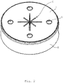
- FIG. 1 shows the top view of a device 1.
- the second housing wall surface 2 is shown, which has the second opening 4 in the middle.
- the second opening 4 is thus delimited and spanned by the second housing wall surface 2 .
- the second opening 4 is shown as a radial slit opening with eight slits.
- the slots extend radially outward.
- four slits are always of equal length in their outward radial extension. This allows a particularly good fixation, support and centering implements with different shapes and geometries to be carried out through the opening 4 can be ensured.
- the housing wall surface 2 in this exemplary embodiment has four light sources 6 which are arranged in a rotationally symmetrical manner.
- the lighting means 6 are embedded in the housing wall surface 2 and are spanned by this material in terms of material. In this case, the illuminants 6 would not be freely accessible and would not be protected from dust, dirt or water (not shown).
- the lighting means 6 it is also conceivable, as shown here, for the lighting means 6 to be let open only in the housing wall surface 2, so that a particularly effective and high quantity of light can be ensured. It has proven particularly advantageous that the housing body 8 and the two housing wall surfaces 2.10 have a wall thickness of 2 mm. This ensures sufficient stability but at the same time sufficient flexibility when force is applied.
- the housing wall surface 2 can have at least one, here two, display means 27 .
- these display means 27 are in the form of LED lamps.
- the display means 27 are used to visually display the state of charge of the power source, so that the user always knows when he needs to recharge the device. For example, if the green LED lamp lights up, this indicates that the charging status is correct. If the red LED lamp lights up, this shows that the power source only has a low residual energy supply and the user should start the charging process as soon as possible.
- the device 1 shown here has a diameter of 40-90 mm, more advantageously 60 mm. Furthermore, it has proven to be advantageous if the inside diameter of the passage volume (not shown) has an inside diameter of 15-45 mm, even more advantageously 25 mm.
- the device 1 has an extension in the vertical direction of 15-25 mm, more advantageously 17 mm. With these geometries, a device 1 that is particularly stable but also easy to deploy and use is created.
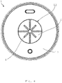
- figure 2 shows a perspective view of the device 1.
- the second housing wall surface 2 is also shown here, which has four light sources 6, for example LED lamps.
- the second opening 4 is designed as a radial slot opening.
- the housing body 8 forms the lateral surface and the outer boundary of the housing.
- the geometry of the housing body 8 is concavely curved inwards. As a result, a recessed grip or a grip ring is formed. This is advantageous for the person using it, since the device 1 can be held particularly securely in the hand through this recessed grip or ring grip while the working device is being guided through the device 1 .
- FIG 3 shows a perspective bottom view of the device 1.
- the housing body 8, which is delimited by the first housing wall surface 10, is also shown here.
- the first housing wall surface 10 has the first opening 12 .
- the first opening 12 is arranged centrally.
- the first opening 12 has a round diameter.
- actuating means 30 and spacer element 36 are also shown.
- figure 4 shows the bottom view figure 3 . It can be seen that the two openings 4,12 are arranged on a common axis of rotation. This is advantageously the central axis of the device. As a result, the implement to be guided through or other objects (not shown) can be guided through the device and reliably held by it in a particularly easy manner.
- figure 5 shows a further perspective view from below, where the concave housing body 8 is shown again. Furthermore, the free passage volume 14 , which is enclosed by the housing body 8 , is shown through the first opening 12 in the perspective representation.
- the projections shown also provide better grip when in use. In addition, the projections also serve as shock protection.
- FIG 6 shows an exploded view of the device 1 with the different components.
- the second housing wall surface 2 is already firmly formed with the housing body 8, for example was produced in one step.
- the housing wall surface 2 has four openings 16 in this exemplary embodiment.
- a circuit board 18 is shown, which has the control unit 20 and/or the power source 22 .
- four light sources 6 are also arranged on circuit board 18 .
- the circuit board also has a through opening 24 on.
- the first housing panel 10 is shown.
- the circuit board 18 can be inserted and/or arranged in the housing wall surface 2 shown here with the housing body 8 arranged thereon, so that the lighting means 6 can be inserted and at least partially guided through the openings 16 provided in the housing wall surface 2.
- the housing wall surface 10 forms the conclusion. It also has a further through opening 32 for at least partially accommodating the actuating means (not shown). Furthermore, the housing wall surface 10 has a further through-opening 34 for at least partially accommodating the spacer element (not shown).
- the internal cavity can, for example, be cast or injected, so that a device 1 formed in one piece ultimately results.
- figure 7 shows a further embodiment of the device 1, which is shown as an exploded view.
- D difference to figure 6 consists in that a stabilizing means 26 is arranged inside the housing body 8 .
- the actuation means 30 is designed to be contact-connected on the circuit board 18 .
- the housing wall surface 10 also advantageously has a through-opening 32 through which the actuating means 30 can be passed at least partially.
- the actuating means 30 penetrates the through-opening 32 to such an extent that the actuating means 30 can be actuated, for example pressed, in a simple manner.
- the application of compressive force for example by finger pressure, is then sufficiently large to correspondingly control the lighting means 6 and switch them on and/or off.
- the actuating means 30 can be arranged elevated relative to the circuit board 18 and can be spaced apart from the circuit board 18 by means of spacer feet, but can be coupled thereto in terms of line technology.
- the housing wall surface 10 has a further through-opening 34 through which a spacer element 36 can be passed at least partially.
- the spacer element 36 can be made of flexible, elastic plastic, for example.
- the spacer element 36 is advantageously used for shock absorption during the transition to the working position.
Landscapes
- Engineering & Computer Science (AREA)
- General Engineering & Computer Science (AREA)
- Arrangement Of Elements, Cooling, Sealing, Or The Like Of Lighting Devices (AREA)
Applications Claiming Priority (1)
| Application Number | Priority Date | Filing Date | Title |
|---|---|---|---|
| DE102021106818.5A DE102021106818B3 (de) | 2021-03-19 | 2021-03-19 | Vorrichtung zur Ausleuchtung von Arbeitsbereichen, Verfahren zu deren Benutzung und Verwendung |
Publications (1)
| Publication Number | Publication Date |
|---|---|
| EP4060227A1 true EP4060227A1 (fr) | 2022-09-21 |
Family
ID=80930382
Family Applications (1)
| Application Number | Title | Priority Date | Filing Date |
|---|---|---|---|
| EP22163280.5A Withdrawn EP4060227A1 (fr) | 2021-03-19 | 2022-03-21 | Dispositif d'éclairage des zones de travail, son procédé d'utilisation et utilisation |
Country Status (2)
| Country | Link |
|---|---|
| EP (1) | EP4060227A1 (fr) |
| DE (1) | DE102021106818B3 (fr) |
Families Citing this family (2)
| Publication number | Priority date | Publication date | Assignee | Title |
|---|---|---|---|---|
| DE102022105455A1 (de) | 2022-03-08 | 2023-09-14 | Tanja Tartler | Beleuchtungsvorrichtung zur Anbringung an einem stiftartigen Werkzeug, insbesondere einem Schraubendreher oder einem Lackstift |
| DE102023130097B4 (de) * | 2023-10-31 | 2025-11-13 | Gregor Leinweber | Begräbnisvorrichtung für Urnengräber |
Citations (3)
| Publication number | Priority date | Publication date | Assignee | Title |
|---|---|---|---|---|
| US5845986A (en) * | 1996-09-24 | 1998-12-08 | Breen; William Charles | Light for manual rotary tool |
| CN200982612Y (zh) * | 2006-12-08 | 2007-11-28 | 赵美莲 | 附挂型工具灯 |
| US20140293590A1 (en) * | 2013-04-01 | 2014-10-02 | Vinod V. Pathy | Lighting device |
Family Cites Families (3)
| Publication number | Priority date | Publication date | Assignee | Title |
|---|---|---|---|---|
| FR2934356B1 (fr) | 2008-07-24 | 2010-09-17 | Centre Nat Rech Scient | Dispositif de support d'un systeme d'eclairage amovible et autoporte pour hublot. |
| DE102013114025B4 (de) | 2013-12-13 | 2017-07-20 | Dr. Schneider Kunststoffwerke Gmbh | Vorrichtung in einem Kraftfahrzeug |
| DE102019116223A1 (de) | 2019-06-14 | 2020-12-17 | Heiko Baumgartner | Mobile Chirurgische Leuchte |
-
2021
- 2021-03-19 DE DE102021106818.5A patent/DE102021106818B3/de active Active
-
2022
- 2022-03-21 EP EP22163280.5A patent/EP4060227A1/fr not_active Withdrawn
Patent Citations (3)
| Publication number | Priority date | Publication date | Assignee | Title |
|---|---|---|---|---|
| US5845986A (en) * | 1996-09-24 | 1998-12-08 | Breen; William Charles | Light for manual rotary tool |
| CN200982612Y (zh) * | 2006-12-08 | 2007-11-28 | 赵美莲 | 附挂型工具灯 |
| US20140293590A1 (en) * | 2013-04-01 | 2014-10-02 | Vinod V. Pathy | Lighting device |
Also Published As
| Publication number | Publication date |
|---|---|
| DE102021106818B3 (de) | 2022-06-30 |
Similar Documents
| Publication | Publication Date | Title |
|---|---|---|
| EP4060227A1 (fr) | Dispositif d'éclairage des zones de travail, son procédé d'utilisation et utilisation | |
| DE29722309U1 (de) | Schlauchkupplung mit Sicherheits-Verriegelungseinrichtung | |
| DE102018116477A1 (de) | Steckverbindungswerkzeug | |
| EP2335327B1 (fr) | Dispositif pour prise multiple pour la reception de connexions a fiches | |
| DE20318583U1 (de) | Ladesteckverbindersatz mit Adapter | |
| DE3925293A1 (de) | Vorrichtung zum loesbaren verbinden einer druckmittelleitung an einem druckmittelanschluss | |
| DE20001996U1 (de) | Werkzeug mit Beleuchtungsfunktion | |
| DE1910180A1 (de) | Aufwaschbuerste | |
| DE20105896U1 (de) | Rahmen mit Montageplatte für elektrische Einrichtungen | |
| DE20306830U1 (de) | Schmuckstück mit einem lösbar befestigten Zierteil | |
| DE29819618U1 (de) | Messer | |
| DE29906009U1 (de) | Feuchtraumleuchte | |
| DE102005001642B4 (de) | Befestigungsvorrichtung an Sanitäreinrichtungen | |
| DE10342395A1 (de) | Hilfsmittel zur Verriegelung einer Steckverbindung | |
| DE602005000748T2 (de) | Kombinierte Haarschneidescherenanordnung | |
| DE2607429C2 (de) | Gartenleuchte | |
| DE102010017169A1 (de) | Dentalmodell-Trägersystem | |
| DE4024758A1 (de) | Einbaulautsprecher, insbesondere autolautsprecher | |
| DE102014000767B4 (de) | Künstlicher Weihnachtsbaum und Verfahren zu dessen Aufbau | |
| DE830683C (de) | Leuchte fuer Aussenbeleuchtung | |
| DE4014802C2 (fr) | ||
| DE102016013374B4 (de) | Universelle Befestigungsvorrichtung für Beleuchtungseinrichtungen | |
| DE29906741U1 (de) | Leuchte | |
| DE10229327A1 (de) | Reinigungsgerät | |
| EP2963342A1 (fr) | Lampe |
Legal Events
| Date | Code | Title | Description |
|---|---|---|---|
| PUAI | Public reference made under article 153(3) epc to a published international application that has entered the european phase |
Free format text: ORIGINAL CODE: 0009012 |
|
| STAA | Information on the status of an ep patent application or granted ep patent |
Free format text: STATUS: THE APPLICATION HAS BEEN PUBLISHED |
|
| AK | Designated contracting states |
Kind code of ref document: A1 Designated state(s): AL AT BE BG CH CY CZ DE DK EE ES FI FR GB GR HR HU IE IS IT LI LT LU LV MC MK MT NL NO PL PT RO RS SE SI SK SM TR |
|
| STAA | Information on the status of an ep patent application or granted ep patent |
Free format text: STATUS: THE APPLICATION IS DEEMED TO BE WITHDRAWN |
|
| 18D | Application deemed to be withdrawn |
Effective date: 20230322 |