EP4060232B1 - Leistungserfassung und luftzahlregelung mittels sensoren im feuerraum - Google Patents
Leistungserfassung und luftzahlregelung mittels sensoren im feuerraum Download PDFInfo
- Publication number
- EP4060232B1 EP4060232B1 EP21162830.0A EP21162830A EP4060232B1 EP 4060232 B1 EP4060232 B1 EP 4060232B1 EP 21162830 A EP21162830 A EP 21162830A EP 4060232 B1 EP4060232 B1 EP 4060232B1
- Authority
- EP
- European Patent Office
- Prior art keywords
- combustion
- signal
- power
- sensor
- combustion power
- Prior art date
- Legal status (The legal status is an assumption and is not a legal conclusion. Google has not performed a legal analysis and makes no representation as to the accuracy of the status listed.)
- Active
Links
Images


Classifications
-
- F—MECHANICAL ENGINEERING; LIGHTING; HEATING; WEAPONS; BLASTING
- F23—COMBUSTION APPARATUS; COMBUSTION PROCESSES
- F23N—REGULATING OR CONTROLLING COMBUSTION
- F23N1/00—Regulating fuel supply
- F23N1/02—Regulating fuel supply conjointly with air supply
- F23N1/022—Regulating fuel supply conjointly with air supply using electronic means
-
- F—MECHANICAL ENGINEERING; LIGHTING; HEATING; WEAPONS; BLASTING
- F23—COMBUSTION APPARATUS; COMBUSTION PROCESSES
- F23N—REGULATING OR CONTROLLING COMBUSTION
- F23N1/00—Regulating fuel supply
- F23N1/02—Regulating fuel supply conjointly with air supply
-
- F—MECHANICAL ENGINEERING; LIGHTING; HEATING; WEAPONS; BLASTING
- F23—COMBUSTION APPARATUS; COMBUSTION PROCESSES
- F23N—REGULATING OR CONTROLLING COMBUSTION
- F23N5/00—Systems for controlling combustion
- F23N5/02—Systems for controlling combustion using devices responsive to thermal changes or to thermal expansion of a medium
-
- F—MECHANICAL ENGINEERING; LIGHTING; HEATING; WEAPONS; BLASTING
- F23—COMBUSTION APPARATUS; COMBUSTION PROCESSES
- F23N—REGULATING OR CONTROLLING COMBUSTION
- F23N5/00—Systems for controlling combustion
- F23N5/18—Systems for controlling combustion using detectors sensitive to rate of flow of air or fuel
-
- F—MECHANICAL ENGINEERING; LIGHTING; HEATING; WEAPONS; BLASTING
- F23—COMBUSTION APPARATUS; COMBUSTION PROCESSES
- F23N—REGULATING OR CONTROLLING COMBUSTION
- F23N2225/00—Measuring
- F23N2225/08—Measuring temperature
-
- F—MECHANICAL ENGINEERING; LIGHTING; HEATING; WEAPONS; BLASTING
- F23—COMBUSTION APPARATUS; COMBUSTION PROCESSES
- F23N—REGULATING OR CONTROLLING COMBUSTION
- F23N2239/00—Fuels
- F23N2239/04—Gaseous fuels
-
- F—MECHANICAL ENGINEERING; LIGHTING; HEATING; WEAPONS; BLASTING
- F23—COMBUSTION APPARATUS; COMBUSTION PROCESSES
- F23N—REGULATING OR CONTROLLING COMBUSTION
- F23N2900/00—Special features of, or arrangements for controlling combustion
- F23N2900/05005—Mounting arrangements for sensing, detecting or measuring devices
Definitions
- the present disclosure relates to controls and/or regulation as used in combustion devices, such as gas burners, in connection with combustion sensors.
- Combustion sensors in combustion devices are, for example, ionization electrodes and/or optical sensors.
- the present disclosure relates to the regulation and/or control of combustion devices in the presence of hydrogen gas.
- external influences can affect the air ratio and/or the combustion output.
- Such external influences are, for example, the inlet pressure of the fuel, in particular the fuel gas, and the fuel composition.
- Further examples of external influences are the ambient temperature, the ambient pressure and changes in the air supply path and in the exhaust gas path of the combustion device.
- such sensors which monitor the flame in a safety-related manner can be included in the control of the combustion output and/or the air ratio of a combustion device.
- Optical flame monitoring has hitherto been used for the combustion of pure hydrogen in a combustion device. Meanwhile, optical sensors for recording signals during combustion are expensive.
- thermocouples and/or resistance temperature sensors are conceivable as sensors for recording combustion signals.
- Thermocouples and/or resistance temperature sensors are to be thermally coupled to the supply air and/or the mixture and/or the exhaust gas and/or the plasma of a combustion at a combustion device.
- Thermocouples and/or resistance temperature sensors are also thermally coupled to the mechanical mount. As a result of such couplings, thermocouples and/or resistance temperature sensors have hitherto tended to be too slow for monitoring a combustion process.
- EP1154202A2 A European patent application EP1154202A2 was filed on April 27, 2001 by SIEMENS BUILDING TECH AG. The application was published on November 14, 2001.
- EP1154202A2 deals with a control device for a burner.
- EP1154202A2 takes a priority from May 12, 2000 claim.
- To EP1154202A2 is a granted European patent EP1154202B1 before.
- EP1154202B2 distinguishes between fuel gases with a low and high calorific value.
- Two characteristic curves are used to differentiate between the two fuel gases.
- the two characteristic curves each relate to a control signal for an actuator of the combustion device over a fan speed of the combustion device.
- Control signals which correspond to the characteristic curves, are weighted for controlling the combustion device.
- EP1154202B2 the use of additional sensors to control the combustion device. Those additional sensors influence the positions of actuators of the combustion device based on their sensor results. Mentions as an example of measurement data obtained from those additional sensors EP1154202B2 a change in boiler temperature.
- DE102004030300A1 was filed on June 23, 2004 by EBM PAPST LANDSHUT GMBH. The application was published on January 12, 2006. DE102004030300A1 deals with a method for setting an operating parameter of a combustion device.
- DE102004055716A1 deals with a procedure for the regulation and control of a combustion device.
- DE102004055716A1 takes priority from June 23, 2004 claim.
- DE102004055716A1 also discloses a mixing area into which an air supply and a gas supply open.
- a line leads out of the mixing area. The line ends at a burner part.
- a flame is arranged above the burner part.
- a temperature sensor can be arranged, for example, in the area of the flame, but also on the burner in the vicinity of the flame.
- a thermocouple can also be used as a temperature sensor.
- DE102004055716A1 teaches the regulation of the temperature Tactual generated by a firing device to a target temperature Tsoll . In this case, a characteristic curve is used which indicates the setpoint temperature T set as a function of the mass flow of air and/or the load of the firing device.
- the air ratio ⁇ remains constant as a further parameter.
- WO2006/000367A1 deals with a method for setting an air ratio in a combustion device.
- WO2006/000367A1 claims a priority dated June 23, 2004.
- WO2015/113638A1 discloses a monitoring device by means of which a gas supply is switched off in the absence of a flame.
- the monitoring device cooperates with a switch-off device comprising a valve.
- the monitor may include a thermocouple or other sensor.
- the monitoring device is therefore safety-related.
- a Japanese patent application JP2017040451A was filed on August 21, 2015 by NORITZ CORP . The application was published on February 23, 2017. JP2017040451A handles an incinerator.
- JP2017040451A deals JP2017040451A with the detection of a flame temperature, taking into account the delays of the respective sensor.
- Thermocouples and thermistors are mentioned as sensors.
- a prediction unit is used to account for those delays.
- the prediction unit obtains a value by multiplying a difference between a temperature detected in the past and a current temperature by a coefficient. That value is added to the currently recorded temperature.
- the coefficient required to determine that value depends on a delay time and on a predetermined period of time.
- DE10045272A1 discloses a firing device for gaseous fuels in which a plurality of temperature sensors are arranged in the flame area.
- Delays caused by sensors are included in the 2020 technical specification of RTD platinum sensors from IST.
- the response time for a sensor to track 63 percent of a temperature change due to delays varies between 2.5 and 40 seconds. In general, the response time depends on the dimensions of the respective sensor.
- a pneumatic gas-air combination and/or an electronic combination can be used to regulate a combustion device.
- a modulation range of one to seven can usually be achieved using a pneumatic gas-air combination.
- the combustion output and the air supply only depend on the fan speed. If the use of other sensors is too complex, a correction of environmental influences is hardly possible.
- environmental influences relate, for example, to air temperature, air pressure and changes in the supply air path or exhaust gas path of the combustion device.
- An electronic network for the combustion of hydrogen requires additional sensors, for example to detect and safeguard the amount of fuel gas, in order to adjust the amount of fuel gas without combustion control. Meanwhile, such additional sensors are expensive.
- the aim of the present disclosure is to provide a closed-loop and/or open-loop control system that enables combustible gases containing hydrogen to be burned.
- an aim of the present disclosure is to provide regulation and/or control that achieves a sufficient degree of modulation.
- Such a regulation can also be used for fuel gases containing hydrocarbons and/or for a mixture of fuel gases containing hydrocarbons with hydrogen.
- the signal from the temperature sensor essentially depends on its position in the combustion chamber of a combustion device. It must be taken into account here that the temperature signal is a function of the supply of the fuel-air mixture and thus depends on the combustion output. In addition, the temperature signal also depends on the mixing ratio between fuel and air and thus on the air ratio. It is hardly possible to obtain an unambiguous assignment for a measured temperature value to exactly one combination of combustion output and air ratio with just one temperature sensor. Therefore, an additional signal is usually required. This signal is usually the air supply as a representative of a mixture supply or combustion output.
- the air ratio can then be corrected using a specified characteristic curve.
- a procedure is in EP1902254B1 described, where in EP1902254B1 the measured temperature is given in the value range as a function of air ratio and combustion output.
- a less complex sensor does not record any fluctuations in the ambient conditions such as air temperature, air pressure or fluctuations in the supply air path and/or exhaust gas path.
- Such a less complex sensor is, for example, the fan speed detection of the fan. Consequently, that sensor has the disadvantage that it only incompletely determines the air supply.
- the present disclosure addresses those difficulties by placing more than one sensor in the furnace of a combustor.
- more than one temperature sensor placed in the firebox of the combustion device.
- the signals from both sensors, in particular both temperature sensors are read out and processed into values for a combustion output.
- the signals from both sensors, in particular both temperature sensors can likewise each be processed into a value for an air ratio ⁇ . It can then be regulated and/or controlled on the basis of the determined combustion line and/or the determined air ratio ⁇ .
- ambiguities can be resolved by arranging a further sensor, in particular a further temperature sensor, in the combustion chamber.
- a signal is read from the additional sensor, in particular from the additional temperature sensor.
- the signal read out is processed to a value of a combustion output and included in the determination of a current combustion output of the combustion device.
- a feed signal in the evaluation.
- a supply signal can be, for example, a fan speed of a fan in an air supply duct.
- a supply channel can be a signal from a flow sensor in the air supply channel or in the fuel supply channel.
- a supply signal can be obtained from an air damper position and/or from a position of a fuel actuator. The use of a feed signal has the advantage that the assignment of feed signal to combustion power is often unambiguous.
- the two characteristic curves for determining the pairs of combustion output are specified for a specified air ratio. With the appropriate positioning of the two sensors in the combustion chamber, there is exactly one pair of points from the two sensor values at which both combustion outputs are the same for all possible air ratio values
- the combustion output can be determined in the range of values as a function of the respective measurement signal for a specified target value of the air ratio.
- the determination is made for each sensor arranged in the combustion chamber. In this way, both the air ratio and the combustion output can be adjusted to specified target values.
- the combustion power depending on the associated sensor signal can be stored as a polynomial for both functions.
- the two functions can be stored as a sequence of points between which linear interpolation is carried out over the minimum distance between the two points. If additional sensors are used, a function of the combustion power is stored in the value range of three or more sensors.
- Another sensor can be, for example, a third sensor in the combustion chamber or a feed sensor.
- the regulation takes place, for example, by first adjusting the air actuator or, alternatively, the fuel actuator until the combustion outputs from the two are the same or are close to one another.
- the combustion output is then calculated, for example, as the average of the two calculated combustion outputs.
- the air actuator and fuel actuator are then adjusted in such a way that the calculated combustion output is at its target value, for example via a control loop. Any resulting deviation of the air ratio from the target value is readjusted again via the air actuator or alternatively the fuel actuator. As a result of the readjustment, the combustion outputs calculated from the two measurement signals are the same again.
- the air ratio and combustion output can be set together within a dead band of the target values using a multi-loop controller.
- Changes caused by external influences on the fuel can be corrected by correcting the air ratio.
- a change in the fuel composition initially has an effect on the air ratio.
- a deviation in the air ratio is corrected by the method disclosed here.
- a change in the fuel inlet pressure and/or the fuel temperature and/or the air pressure and/or the air temperature can be corrected via the air ratio control.
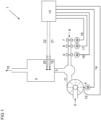
- FIG 1 Fig. 1 shows a combustion device 1 such as a wall-mounted gas burner and/or a floor-standing gas burner.
- a flame of a heat generator burns in the combustion chamber 2 of the combustion device 1 .
- the heat generator exchanges the thermal energy of the hot combustion gases into another fluid such as water.
- a hot water heating system is operated and / or heated drinking water.
- a good can be heated, for example in an industrial process, with the thermal energy of the hot fuels and/or combustion gases.
- the heat generator is part of a system with combined heat and power generation, for example a motor of such a system.
- the heat generator is a gas turbine.
- the heat generator can be used to heat water in a plant for the production of lithium and/or lithium carbonate.
- the exhaust gases 10 are discharged from the combustion chamber 2, for example via a chimney.
- the air supply 5 for the combustion process is supplied via a (motor) driven fan. Via the signal line 14, a control and/or regulating device 13 specifies the air supply V L to the blower that it is to convey. The fan speed of the fan speed sensor 12 thus becomes a measure of the air supply 5.
- the fan speed determined by the sensor 12 is reported back to the control and/or regulating device 13 by the fan and/or by the drive 4 and/or the air actuator 4 of the fan.
- the control and/or regulating device 13 determines the speed of the fan via the signal line 15.
- the control and/or regulating device 13 preferably includes a microcontroller.
- the control and/or regulating device 13 ideally includes a microprocessor.
- the control and/or regulating device 13 can be a regulating device.
- the control device preferably includes a microcontroller.
- the control device ideally includes a microprocessor.
- the controller may include a proportional and integral controller.
- the control device can comprise a proportional and integral and derivative controller.
- control and/or regulating device 13 can comprise a (logic) gate arrangement which can be programmed in the field.
- control and/or regulating device 13 can comprise an application-specific integrated circuit.
- the signal line 14 or 15 comprises an optical waveguide.
- the signal line 14 or 15 is designed as an optical waveguide.
- Optical fibers provide advantages in terms of galvanic isolation and protection against explosions.
- the flap and/or valve position can be used as a measure for the air supply 5 .
- a measured value derived from the signal of a pressure sensor 12 and/or mass flow sensor 12 and/or volume flow sensor 12 can be used.
- the air supply V L is the value of the current air flow rate.
- the air flow rate may be measured and/or reported in cubic meters of air per hour.
- the air supply V L can thus be measured and/or specified in cubic meters of air per hour.
- the fuel supply V B is set and/or regulated by the control and/or regulating device 13 with the aid of at least one fuel actuator 7-9 and/or at least one (motor-driven) adjustable valve 7-9.
- the fuel 6 is a fuel gas.
- a combustor 1 can then be connected to various fuel gas sources, for example sources with a high proportion of methane and/or sources with a high proportion of propane. Provision is also made for the combustion device 1 to be connected to a source of a gas or a gas mixture, the gas or the gas mixture comprising hydrogen. In a special embodiment it is provided that the gas or the gas mixture comprises more than five percent, in particular more than five percent of the amount of hydrogen.
- the gas or the gas mixture only or includes essentially only hydrogen gas.
- the fuel and/or the gas and/or the gas mixture comprises variably zero to thirty percent of the amount of hydrogen gas.
- the quantity of fuel gas is set by the control and/or regulating device 13 by at least one (motor-driven) adjustable fuel valve 7 - 9 .
- the control value, for example a pulse width modulated signal, of the gas valve 7 - 9 is a measure of the amount of fuel gas. It is also a value for the fuel supply V B .
- a gas valve is used as the fuel actuator 7 - 9, the position of a valve can be used as a measure for the quantity of fuel gas.
- a fuel actuator 7-9 and/or a fuel valve 7-9 are set using a stepping motor. In that case, the stepping position of the stepping motor is a measure of the amount of fuel gas.
- the fuel valve and/or the fuel flap can also be integrated in a unit with at least one or more safety shut-off valves 7, 8.
- a signal line 16 connects the fuel actuator 7 to the control and/or regulating device 13.
- a further signal line 17 connects the fuel actuator 8 to the control and/or regulating device 13.
- Another further signal line 18 connects the fuel actuator 9 to the control and/or regulating device 13. or control device 13.
- the signal lines 16-18 each comprise an optical waveguide. Optical fibers provide advantages in terms of galvanic isolation and protection against explosions.
- At least one of the fuel valves 7 - 9 can be a valve controlled internally via a flow and/or pressure sensor, which valve receives a target value and regulates the actual value of the flow and/or pressure sensor to the target value.
- the flow and/or pressure sensor can be implemented as a volume flow sensor, for example as a turbine wheel meter and/or as a bellows meter and/or as a differential pressure sensor.
- the flow and/or pressure sensor can also be designed as a mass flow sensor, for example as a thermal mass flow sensor.
- FIG 1 also shows a combustion device 1 with a first sensor 19.
- the sensor 19 is preferably arranged in the combustion chamber 2.
- the first sensor 19 advantageously includes a first temperature sensor 19.
- the first sensor 19 is a first temperature sensor 19.
- a signal line 21 connects the temperature sensor 19 to the control and/or regulating device 13.
- the signal line 21 comprises an optical waveguide.
- Optical fibers provide advantages in terms of galvanic isolation and protection against explosions.
- FIG 1 also shows a combustion device 1 with a second sensor 20.
- the sensor 20 is preferably arranged in the combustion chamber 2.
- the second sensor 20 advantageously comprises a second temperature sensor 20.
- the second sensor 20 is a second temperature sensor 20.
- a signal line 22 connects the temperature sensor 20 to the control and/or regulating device 13.
- the signal line 22 comprises an optical waveguide.
- Optical fibers provide advantages in terms of galvanic isolation and protection against explosions.
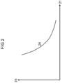
- FIG 2 shows the signal curve 24 of the combustion output 23 over the sensor signal of the first sensor 19 for a solid combustion gas at a predetermined, constant mixing ratio.
- the sensor 19 is arranged in such a way that the combustion output 23 can be clearly assigned to the sensor signal.
- Such a signal course 24 is obtained, for example, when a temperature sensor 19 is attached close to the burner 3 .
- Characteristic curve 24 differs from that in EP1902254B1 mentioned characteristic characterized in that the characteristic 24 along the ordinate has the burning power 23 and not the temperature signal. Consequently, via the in FIG 2 characteristic curve 24 shown from the signal, the combustion power 23 can be determined.
- the air ratio ⁇ is set for each combustion output 23 for this purpose.
- the characteristic curve 24 is stored in the open-loop and/or closed-loop control device 13 .
- the assignment also takes place there.
- the characteristic curve 24 can be stored in an electronic circuit on the first temperature sensor 19 or in any other unit.
- the evaluation also takes place there.
- the combustion output 23 can be determined directly with the characteristic curve 24, so that an air supply sensor is not required. If the fuel gas metering is assigned directly to the air supply 5, then the combustion output 23 and the air supply 5 are also assigned directly to one another. In this way, the air supply 5 can be set via the stated assignment between the combustion output 23 and the air supply 5 and via the control signal according to the line 14 . As an alternative, the air supply 5 can be regulated in this way via a closed loop control. In a preferred embodiment, the air supply signal is present, but the association between the air supply 5 and the signal is subject to external influences. These can be changes, for example, in the air temperature and/or the ambient pressure and/or the supply air/exhaust gas path.
- a signal where such changes are not compensated for is the fan speed signal of the fan 4 or the position feedback of a damper.
- the association between air supply 5 and the sensor signal on line 12 in relation to reference conditions can be recalibrated regularly during operation. The recalibration takes place with the help of the sensor signal and the combustion output 23 determined via the characteristic curve 24 as well as with the help of the assignment between the combustion output 23 and the air supply 5.
- This process has the advantage that the air supply 5 and thus the combustion output 23 can be changed quickly.
- the correction via the characteristic curve 24 takes place much more slowly.
- the characteristic curve of a gas supply sensor can also be corrected, for example the fuel supply based on the position of a gas flap setting.
- the air control signal on line 14 and thus the air supply 5 are assigned directly to the fuel metering.
- the course of the characteristic curve 24 depends heavily on the position of the sensor in the combustion chamber 2 .
- a sensor position close to or directly on the burner 3 has the disadvantage that the dynamics of the sensor signal is impaired by the heat capacity of the burner 3 . This makes the regulation sluggish.
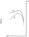
- 3 shows the course of a characteristic curve 24 of the combustion output 23 as a function of the sensor signal from line 21 when the sensor 19 is arranged in the combustion chamber 2 in or near the flame.
- a second sensor 20 is installed in the combustion chamber 2, which assigns the sensor signal from line 22 to the combustion output 23 via a characteristic curve 25 that deviates from characteristic curve 24. So that a clear assignment of the two sensor values to the combustion output 23 as a function of two variables is possible via the two characteristic curves 24 and 25, for all values of the combustion output 23 in the value range of the possible combustion outputs 23, the pair of points with the signals on lines 21 and 22, the is assigned to the respective value of the combustion output 23 via the characteristic curves 24 and 25 only occur once.
- the two characteristic curves 24 and 25 can be stored as polynomials in the open-loop and/or closed-loop control device 13 .
- the assignment then takes place by means of a rule with which the different fuel gas outputs for the currently recorded signals 21 and 22 are calculated using the characteristic curves 24 and 25 .
- the characteristic curves 24 are stored as a sequence of pairs of values (21/23) and (22/23).
- the signals from the lines 21 and 22 can lie between the corresponding stored pairs of values (21/23) and (22/23). Adjacent pairs of values (21/23) and (22/23) corresponding to the signals from lines 21 and 22 are then determined. Linear interpolation is used to determine the combustion output 23 .
- the discrepancies in the burning power 23 for the signals from the lines 21 and 22 are then determined.
- the absolute value of the difference between all calculated combustion powers 23 from characteristic curve 24 and all calculated values from characteristic curve is formed.
- the mean value or one of the two calculated values is taken as the assigned value from the two combustion outputs 23 with the smallest difference.
- Exist for the signals from the lines 21, 22 in the characteristics 24, 25 only exactly one burning power 23 for at least one of the two characteristics 24, 25, so this is taken as the result.
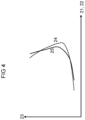
- FIG 4 shows that the two characteristic curves can also intersect. As long as the above-mentioned condition for the unambiguous assignment is met, the combustion output 23 and thus the air supply 5 can also be determined with such characteristic curves.
- the association can be made unambiguous with the aid of a further signal.
- This further signal can come from a further sensor in the combustion chamber 2, which clarifies this assignment in the case of the respective signals with an ambiguous assignment. With this further sensor in the combustion chamber 2, a further characteristic curve is stored, with which the combustion output 23 can be clearly determined as described above.
- An air supply sensor and/or a fuel supply sensor is particularly preferred as the third sensor. If the fan speed or the position of an air damper is used as the air supply sensor, the returned signal on line 15 can be used to clarify the unambiguous assignment, despite the inaccuracies described above. Such a clarification can take place in particular when the combustible gas values with the same or similar pair of values are far apart.
- the fuel gas values with the same or a similar pair of measured values on the lines 21, 22 are not in the error range of the external influences mentioned.
- the combustion output 23 and from this the air supply 5 can be determined not only from the signals on the lines 21, 22 of the sensors 19, 20 in the combustion chamber 2.
- the fuel supply 6 can be determined for a fixed predetermined mixture of a fuel gas.
- the fuel in particular the fuel gas, can also be metered in the correct ratio to the air supply 5 with the means presented.
- the prerequisite for this is that air supply 5 and fuel supply 6 can be freely adjusted via the respective actuators 4, 9 for air and for fuel.
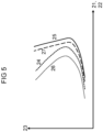
- 5 shows the behavior of the signals on lines 21 and 22 over the burning power 23. 5 relates to the case that the mixture is too lean in relation to the set air ratio ⁇ , i.e.
- characteristic curves 24 and 25 correspond to the sensor signals on the lines 21 and 22 for different combustion outputs 23 when the mixture is set in such a way that the target air ratio ⁇ target is reached. If the mixture becomes leaner, the result is characteristic curve 26 for sensor 19 and characteristic curve 27 for sensor 20. Normally, characteristic curve 24 shifts to characteristic curve 25 by a different amount than characteristic curve 26 to characteristic curve 27 due to the leaner mixture.
- two characteristic surfaces can be stored as a function of the combustion output 23 via the respective temperature values from the lines 21 and 22 and the air ratio ⁇ in each case.
- the combustion output 23 and the air ratio ⁇ can then be clearly determined.
- the prerequisite for this is that for each point of the combustion output 23 and the air ratio ⁇ across all pairs of points that result, the pair of signal values from the lines 21, 22 occurs only once in both areas.
- the current combustion output 23 and the current air ratio ⁇ can be assigned directly to the pair of points.
- the two actuators 4 and 9 can then be corrected to the setpoint.
- a third signal is therefore often necessary in order to clearly determine the combustion output 23 and the air ratio ⁇ .
- This third signal can come from another sensor in the combustion chamber. However, it is preferably the air supply signal from line 14 or 15.
- the third signal can come from the fan speed feedback from a fan speed sensor 12 in the fan or the position of an air flap.
- the third signal can come from the position of a fuel actuator, in particular from a position of a gas flap 9 .
- the regulation takes place by keeping the air supply 5 constant or almost constant via the air actuator 4 .
- the fuel supply 6 is changed by the fuel actuator 9 until the determined values of the combustion power 23 from the two characteristic curves 24, 25 are within a defined threshold value.
- fuel supply 6 is kept constant or almost constant via fuel actuator 9 .
- the air supply 5 is changed via the air actuator 4 until the determined values of the combustion outputs 23 from the two characteristic curves 24, 25 are within a defined threshold value.
- the adjustment direction is determined via the difference between the two determined combustion powers 23, for example by detecting that the difference is decreasing. If further sensor readings are added, the sum of the squared calculated difference values is compared with the specified threshold value, for example. This procedure ensures that the actual air ratio ⁇ actual is at the setpoint air ratio ⁇ setpoint specified according to the characteristic curves 24 , 25 .
- the combustion power P actual is determined by, for example, calculating the arithmetic mean from the two combustion powers 23 determined with the aid of the characteristic curves 24 and 25 .
- the air actuator 4 and at least one fuel actuator 7-9 are adjusted together until the specified combustion output P setpoint is reached.
- the air ratio ⁇ can deviate slightly due to the combustion output adjustment. In this case, the air ratio ⁇ can , as described, be readjusted by adjusting at least one fuel actuator 7-9 or the air actuator 4 at the target combustion output P setpoint .
- combustion output 23 and air ratio ⁇ are corrected directly by adjusting both actuators 4, 7-9. Reaching the respective threshold value for the difference in combustion power 23 is stored as a criterion in the multi-circuit control, as in the first and second variants.
- the first actuator is adjusted more slowly than the second actuator.
- the target values for air ratio ⁇ target and combustion output P target can always be achieved.
- at least one fuel actuator 7-9 is adjusted more slowly than air actuator 4.
- air actuator 4 is adjusted more slowly than at least one fuel actuator 7-9
- Actuators 4 and 7 - 9 is utilized.
- the at least one fuel actuator 7-9 with a stepper motor drive is faster than the air actuator 4 with a fan wheel that can be adjusted by a motor and a corresponding moment of inertia. Variant one is therefore often chosen.
- the procedure presented ensures that during a change in the combustion output, the air ratio ⁇ is first corrected and only then the combustion output 23 .
- the combustion device 1 is always operated with the correct air ratio ⁇ set during the change in combustion output.
- the characteristic curves 24, 25 also correspond to the characteristic curves of the combustion output 23 for the respective sensors 19, 20 at a predetermined air ratio ⁇ set .
- the setpoint air ratio ⁇ setpoint has a course over the combustion output 23 that is defined by the characteristic curves 24, 25 and is arbitrary over a wide range.
- setpoint air ratio ⁇ setpoint can have an increasing or decreasing profile with combustion output 23 .
- the progression of setpoint air ratio ⁇ sol over combustion output 23 is constant.
- the characteristic curve 24 of the first sensor 19 is shown at the air ratio target value ⁇ set and at the lean air ratio value 26 .
- the characteristic curve 25 of the second sensor 20 is shown at the air ratio target value ⁇ setpoint and at the lean air ratio value 27 .
- the third sensor signal can be, for example, a fan speed feedback from the fan 4 through the line 15 .
- Air actuator 4 fuel factor 9 air actuator 4 air actuator 4 fuel factor 9 fuel factor 9 air actuator 4 can move on a predetermined characteristic of an air supply sensor 12 .
- the specified characteristic can be based, for example, on feedback of a fan speed or be a characteristic of a position feedback of an air valve.
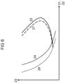
- FIG 7 such a characteristic curve 28 stored in the control and/or regulating device 13 is shown as a reference characteristic curve over the fan speed feedback 15 of a fan speed sensor 12 .
- the characteristic curve 28 relates to a specific and/or well-defined environmental condition.
- a command signal along line 14 of the blower motor or damper position, as well as a feedback position signal along line 15, has a similar signal for a reference condition.
- the signal was linearized in advance via a characteristic stored in the control and/or regulating device 13 from the control signal or a reported position signal for the air supply 5 .
- the characteristic curve 28 can be adapted to the current ambient conditions.
- ambient conditions are, for example, air temperature and/or air pressure and/or changes in the supply air/exhaust gas path.
- the air supply 5 is known as a direct function of the combustion output 23 for the currently measured fan speed or reference control.
- a direct function means that the air supply 5 does not depend on any arguments of the function other than the combustion output 23 .
- the supply determined from characteristic curve 28 is also known. The correction factor can thus be determined for the current air supply 5 as a ratio between the two signals. Since the characteristic curves of the reference air supply signals or the fan speed feedback over the air supply 5 pass through the zero point, characteristic curve 28 can be corrected to characteristic curve 29 .
- Each characteristic value is multiplied by the determined correction factor.
- the combustion output 23 and the air supply 5 can be quickly adjusted via the corrected characteristic curve 29 with the aid of this method. Meanwhile, the air supply 5 can be corrected slowly via the characteristic curves 24, 25. In this way, both processes are decoupled from each other. Fluctuations in the measured values of the combustion output 23 can also be averaged out via an averaging filter, and the combustion output 23 can thus be determined in a stable manner. The combustion output 23 can also be corrected in this way. The speed of a combustion output change is not affected.
- the characteristic on which the fuel actuator 9 moves is in 8 shown.
- Two reference characteristic curves 30, 31, which were determined for different pressures and/or different combustible gas compositions, are stored in the control and/or regulating device 13.
- the characteristic curves 30, 31 describe the gas metering signal over the air supply 5, represented by the corrected signal value of the air supply 5 or the combustion output 23.
- the in this case, the gas metering signal represents the fuel supply and/or gas supply.
- the two characteristic curves 30, 31 were determined under reference conditions, ie for specific inlet pressures and/or fuel gas compositions.
- the characteristic curve 30 was determined with a high-calorific fuel or combustible gas and/or with a high inlet pressure.
- the characteristic curve 31 was determined with a low-calorific fuel or combustible gas and/or with a low inlet pressure. In operation, it is determined what the current ratio between fuel gas and air is by shifting the signals from the sensors 19, 20 in the combustion chamber 2 as described above. The signals are shifted to an unambiguous pair of values on both characteristic curves 24 and 25 by changing the fuel actuator 9 up to this point.
- a ratio can be determined using the weighted average.
- the fuel metering signal and/or the gas metering signal are in this relationship.
- the ratio represents the current fuel parameters and/or gas parameters, such as fuel gas composition and/or inlet pressure and/or fuel gas temperature. Because the same ratio applies to all combustion output signals with the same fuel parameters and/or gas parameters, the characteristic curve 32 can be calculated.
- the fuel actuator 9 can quickly change its combustion output 23 on the characteristic curve 32 in accordance with the current fuel parameters and/or gas parameters. In particular, the fuel actuator 9 can quickly change its position based on the characteristic curve 32 according to the current fuel parameters and/or gas parameters.
- At least one fuel parameter and/or gas parameter changes this is achieved by correcting the weighting ratio by adapting the sensor signals on lines 21 and 22 to the characteristic curves 24, 25 as described above.
- the new characteristic can be calculated with the new weighting parameter.
- the method for calculating the corrected characteristic curve 32 for controlling the fuel actuator 9 with different fuel parameters and/or gas parameters corresponds to the method as in FIG EP1154202B2 described.
- a change in the fuel composition or the gas inlet pressure can also be corrected with the method described, because these parameters affect the air ratio ⁇ .
- the air ratio ⁇ is corrected by adapting it to the characteristic curves 24, 25 as described above.
- the flame can be monitored with the two sensors 19, 20, for example to detect a flame failure.
- the two signals 21, 22 generated by the sensors 19, 20 are used not only for controlling the air ratio ⁇ and the combustion output 23 but also for detecting the presence of a flame.
- At least one signal 21 or 22 can be evaluated for falling below a threshold value.
- the threshold values can be selected differently for sensor signal 21 than for sensor signal 22. If the respective threshold value is not reached, the temperature is so low, for example, that no flame can burn any longer.
- a signal is generated with which the Safety shut-off valves 8.9 are closed via the lines 16, 17 so that no combustible fuel can escape unburned.
- the difference between the two signals 21 and 22 is formed, it being necessary to ensure that both signals do not have the same temperature value during operation. If the flame goes out, the two temperatures quickly equalize. So if the difference between the two signals falls below a predetermined threshold value, this is detected as a loss of flame. It is ensured that the safety shut-off valves 8, 9 are closed.
- the supply signal device (4, 7 - 9, 12) is an air supply sensor in or on an air supply duct.
- the air supply sensor can include, for example, a turbine wheel meter and/or a bellows meter and/or a differential pressure sensor and/or a mass flow sensor.
- the air supply sensor is a turbine wheel meter and/or a bellows meter and/or a mass flow sensor.
- the air supply sensor is in fluid connection with a fluid, in particular with air, in the air supply channel.
- the air supply sensor is also in operative connection with the fluid, in particular with air, in the air supply channel because the fluid acts on the air supply sensor.
- the supply signal device (4, 7 - 9, 12) comprises a fan (4) which acts on the air supply channel.
- the fan (4) can in particular be a motor-driven fan (4).
- the fan (4) is designed to signal, in particular to communicate, its fan speed.
- the fan speed of the fan (4) is a measure of the air supply (5).
- the supply signal device (4, 7 - 9, 12) is a fuel supply sensor in or on a fuel supply channel.
- the fuel supply sensor can include, for example, a turbine meter and/or a bellows meter and/or a differential pressure sensor and/or a mass flow sensor.
- the fuel delivery sensor is a turbine meter and/or a bellows meter and/or a mass flow sensor.
- the fuel supply sensor is in fluid connection with a fluid, in particular with a fuel and/or with a fuel gas, in the fuel supply channel.
- the fuel supply sensor is also in operative connection with the fluid, in particular with the fuel and/or the fuel gas, in the fuel supply channel because the fluid acts on the fuel supply sensor.
- the supply signal device (4, 7-9, 12) comprises at least one fuel actuator (7-9) and/or at least one valve (7-9), which acts on the fuel supply channel.
- the at least one fuel actuator (7 - 9) and/or the at least one valve (7 - 9) can in particular be at least one fuel valve (7 - 9) and/or at least one fuel gas valve (7 - 9).
- the at least one fuel actuator (7 - 9) and/or the at least one valve (7 - 9) is designed to signal, in particular to communicate, its position.
- the position of the at least one fuel actuator (7 - 9) and/or the at least one valve (7 - 9) is a measure of the fuel supply (6).
- the aforementioned disclosure presupposes that the two sensors (19, 20) are positioned in such a way that both temperature values cannot assume the same temperature value during operation when there is a flame in the combustion chamber (2), but the combustion performance (23) from the characteristic curves (24 , 25) can assume the same values.
Landscapes
- Engineering & Computer Science (AREA)
- Chemical & Material Sciences (AREA)
- Combustion & Propulsion (AREA)
- Mechanical Engineering (AREA)
- General Engineering & Computer Science (AREA)
- Regulation And Control Of Combustion (AREA)
Priority Applications (8)
| Application Number | Priority Date | Filing Date | Title |
|---|---|---|---|
| ES21162830T ES2953159T3 (es) | 2021-03-16 | 2021-03-16 | Detección del rendimiento y control de la relación de aire mediante sensores en la cámara de combustión |
| EP21162830.0A EP4060232B1 (de) | 2021-03-16 | 2021-03-16 | Leistungserfassung und luftzahlregelung mittels sensoren im feuerraum |
| PL21162830.0T PL4060232T3 (pl) | 2021-03-16 | 2021-03-16 | Wykrywanie mocy i regulacja współczynnika nadmiaru powietrza za pomocą czujników w komorze spalania |
| ES21186229T ES2957808T3 (es) | 2021-03-16 | 2021-07-16 | Detección de rendimiento y control de factor de aire mediante sensores en la cámara de combustión |
| EP21186229.7A EP4060233B1 (de) | 2021-03-16 | 2021-07-16 | Leistungserfassung und luftzahlregelung mittels sensoren im feuerraum |
| PL21186229.7T PL4060233T3 (pl) | 2021-03-16 | 2021-07-16 | Wykrywanie mocy i regulacja współczynnika nadmiaru powietrza za pomocą czujników w komorze spalania |
| CN202210257034.3A CN115076714B (zh) | 2021-03-16 | 2022-03-16 | 用于调节燃烧设备的方法和计算机程序以及燃烧设备 |
| CN202210256839.6A CN115076713B (zh) | 2021-03-16 | 2022-03-16 | 用于调节燃烧设备的方法和计算机程序以及燃烧设备 |
Applications Claiming Priority (1)
| Application Number | Priority Date | Filing Date | Title |
|---|---|---|---|
| EP21162830.0A EP4060232B1 (de) | 2021-03-16 | 2021-03-16 | Leistungserfassung und luftzahlregelung mittels sensoren im feuerraum |
Publications (2)
| Publication Number | Publication Date |
|---|---|
| EP4060232A1 EP4060232A1 (de) | 2022-09-21 |
| EP4060232B1 true EP4060232B1 (de) | 2023-05-24 |
Family
ID=74884867
Family Applications (2)
| Application Number | Title | Priority Date | Filing Date |
|---|---|---|---|
| EP21162830.0A Active EP4060232B1 (de) | 2021-03-16 | 2021-03-16 | Leistungserfassung und luftzahlregelung mittels sensoren im feuerraum |
| EP21186229.7A Active EP4060233B1 (de) | 2021-03-16 | 2021-07-16 | Leistungserfassung und luftzahlregelung mittels sensoren im feuerraum |
Family Applications After (1)
| Application Number | Title | Priority Date | Filing Date |
|---|---|---|---|
| EP21186229.7A Active EP4060233B1 (de) | 2021-03-16 | 2021-07-16 | Leistungserfassung und luftzahlregelung mittels sensoren im feuerraum |
Country Status (4)
| Country | Link |
|---|---|
| EP (2) | EP4060232B1 (pl) |
| CN (2) | CN115076713B (pl) |
| ES (2) | ES2953159T3 (pl) |
| PL (2) | PL4060232T3 (pl) |
Families Citing this family (2)
| Publication number | Priority date | Publication date | Assignee | Title |
|---|---|---|---|---|
| EP4435322B1 (de) * | 2023-03-24 | 2025-07-02 | Siemens Aktiengesellschaft | Regelung einer verbrennungsvorrichtung |
| DE102023212455B3 (de) * | 2023-11-30 | 2024-12-24 | Siemens Aktiengesellschaft | Automatisierung anhand Sauerstoffkonzentration |
Family Cites Families (33)
| Publication number | Priority date | Publication date | Assignee | Title |
|---|---|---|---|---|
| CZ280159B6 (cs) * | 1987-04-06 | 1995-11-15 | Poludniowy Okreg Energetyczny Katowice Elektrownia Laziska | Zařízení pro řízení energetického bloku |
| JPH0783427A (ja) * | 1993-09-17 | 1995-03-28 | Harman Co Ltd | 燃焼制御装置 |
| JP3094808B2 (ja) * | 1994-09-29 | 2000-10-03 | トヨタ自動車株式会社 | 燃焼装置の燃焼制御方法 |
| JPH08178279A (ja) * | 1994-12-26 | 1996-07-12 | Trinity Ind Corp | 燃焼装置 |
| DE29612014U1 (de) * | 1996-07-10 | 1996-09-05 | Buderus Heiztechnik Gmbh, 35576 Wetzlar | Gasbrenner |
| KR100187955B1 (ko) * | 1996-08-30 | 1999-06-01 | 전주범 | 가스보일러의 저출력영역에서의 역풍대응방법 |
| DE19734574B4 (de) * | 1997-08-09 | 2006-06-14 | Robert Bosch Gmbh | Verfahren und Vorrichtung zum Regeln eines Brenners, insbesondere eines vollvormischenden Gasbrenners |
| DE19820038C2 (de) * | 1998-05-05 | 2000-03-23 | Martin Umwelt & Energietech | Verfahren zum Regeln der Feuerleistung von Verbrennungsanlagen |
| DE10025769A1 (de) * | 2000-05-12 | 2001-11-15 | Siemens Building Tech Ag | Regeleinrichtung für einen Brenner |
| DE10045272C2 (de) * | 2000-08-31 | 2002-11-21 | Heatec Thermotechnik Gmbh | Feuerungseinrichtung mit Überwachung der Flammenlänge und Verfahren zum Steuern oder Regeln dieser Einrichtung |
| DE10145592C1 (de) * | 2001-09-14 | 2003-06-18 | Rational Ag | Verfahren zur Leistungseinstellung gasbetriebener Gargeräte sowie dieses Verfahren nutzendes Gargerät |
| ITAN20020038A1 (it) * | 2002-08-05 | 2004-02-06 | Merloni Termosanitari Spa Ora Ariston Thermo Spa | Sistema di controllo della combustione a sensore virtuale di lambda. |
| DE102004030300A1 (de) | 2004-06-23 | 2006-01-12 | Ebm-Papst Landshut Gmbh | Verfahren zur Einstellung eines Betriebsparameters einer Feuerungseinrichtung und Feuerungseinrichtung |
| EP1761728B1 (de) | 2004-06-23 | 2014-11-19 | ebm-papst Landshut GmbH | Verfahren zur einstellung der luftzahl an einer feuerungseinrichtung und feuerungseinrichtung |
| DE102004055716C5 (de) | 2004-06-23 | 2010-02-11 | Ebm-Papst Landshut Gmbh | Verfahren zur Regelung einer Feuerungseinrichtung und Feuerungseinrichtung (Elektronischer Verbund I) |
| JP4893002B2 (ja) * | 2006-02-06 | 2012-03-07 | 株式会社ノーリツ | 燃焼装置 |
| FR2902408B1 (fr) * | 2006-06-19 | 2008-08-08 | Eurocopter France | Equilibrage en puissance de deux turbomoteurs d'un aeronef |
| DE102007022938A1 (de) * | 2007-05-16 | 2008-11-20 | J. Eberspächer GmbH & Co. KG | Verfahren zur Flammüberwachung bei einem brennstoffbetriebenen Heizgerät |
| JP5360400B2 (ja) * | 2009-08-27 | 2013-12-04 | 株式会社ノーリツ | 燃焼制御方法、燃焼装置およびこの燃焼装置を備えた温水装置 |
| JP2011064402A (ja) * | 2009-09-17 | 2011-03-31 | Hanshin Electric Co Ltd | 燃焼機器の燃焼制御方法 |
| EP2550483B1 (en) * | 2010-03-24 | 2018-03-07 | Bertelli & Partners S.R.L. | Method and device for controlling an atmospheric boiler with an air tight combustion chamber |
| KR101179750B1 (ko) * | 2010-12-15 | 2012-09-04 | 주식회사 경동나비엔 | 출력조절장치를 구비한 가스보일러 및 가스보일러의 출력조절방법 |
| JP5718747B2 (ja) * | 2011-07-06 | 2015-05-13 | リンナイ株式会社 | 燃焼装置 |
| CN102353072B (zh) * | 2011-10-24 | 2013-08-21 | 云南航天工业总公司 | 一种柴油燃烧器输出功率的控制方法及其控制装置 |
| CN202452469U (zh) * | 2012-02-14 | 2012-09-26 | 西安热工研究院有限公司 | 一种新型火力发电机组功率快速调节装置 |
| DE102013226409A1 (de) * | 2013-12-18 | 2015-06-18 | Siemens Aktiengesellschaft | Verfahren zur Regelung und/oder Steuerung der Stellgrößen einer Gasturbine in einem Verbrennungssystem |
| WO2015113638A1 (en) | 2014-02-03 | 2015-08-06 | Electrolux Appliances Aktiebolag | Gas burner assembly and gas cooking appliance |
| JP6550832B2 (ja) * | 2015-03-26 | 2019-07-31 | 株式会社ノーリツ | 燃焼装置 |
| JP6693067B2 (ja) | 2015-08-21 | 2020-05-13 | 株式会社ノーリツ | 燃焼装置 |
| FR3048278A1 (fr) * | 2016-02-25 | 2017-09-01 | La Bonne Chauffe | Dispositif de regulation continue de la puissance d'un systeme de chauffage et procede associe |
| CN207299015U (zh) * | 2017-08-22 | 2018-05-01 | 山东傲天环保科技有限公司 | 一种生物质成型燃料智能化与精细化燃烧控制系统 |
| EP3450848B1 (en) * | 2017-09-01 | 2021-01-06 | Technische Universität Berlin | Method for controlling a combustion apparatus and control device |
| CN108317738B (zh) * | 2018-03-01 | 2023-07-18 | 芜湖美的厨卫电器制造有限公司 | 一种热水器安全控制方法、装置和热水器 |
-
2021
- 2021-03-16 PL PL21162830.0T patent/PL4060232T3/pl unknown
- 2021-03-16 ES ES21162830T patent/ES2953159T3/es active Active
- 2021-03-16 EP EP21162830.0A patent/EP4060232B1/de active Active
- 2021-07-16 ES ES21186229T patent/ES2957808T3/es active Active
- 2021-07-16 EP EP21186229.7A patent/EP4060233B1/de active Active
- 2021-07-16 PL PL21186229.7T patent/PL4060233T3/pl unknown
-
2022
- 2022-03-16 CN CN202210256839.6A patent/CN115076713B/zh active Active
- 2022-03-16 CN CN202210257034.3A patent/CN115076714B/zh active Active
Also Published As
| Publication number | Publication date |
|---|---|
| EP4060232A1 (de) | 2022-09-21 |
| CN115076714A (zh) | 2022-09-20 |
| CN115076714B (zh) | 2025-09-16 |
| CN115076713B (zh) | 2025-09-16 |
| PL4060233T3 (pl) | 2023-11-20 |
| ES2953159T3 (es) | 2023-11-08 |
| EP4060233A1 (de) | 2022-09-21 |
| EP4060233B1 (de) | 2023-06-28 |
| CN115076713A (zh) | 2022-09-20 |
| PL4060232T3 (pl) | 2023-09-11 |
| ES2957808T3 (es) | 2024-01-26 |
Similar Documents
| Publication | Publication Date | Title |
|---|---|---|
| EP2594848B1 (de) | Verfahren zur Steuerung einer Feuerungseinrichtung und Feuerungseinrichtung | |
| DE102010055567B4 (de) | Verfahren zur Stabilisierung eines Betriebsverhaltens eines Gasgebläsebrenners | |
| EP2005066B1 (de) | Verfahren zum starten einer feuerungseinrichtung bei unbekannten rahmenbedingungen | |
| EP1761728B1 (de) | Verfahren zur einstellung der luftzahl an einer feuerungseinrichtung und feuerungseinrichtung | |
| EP1522790B1 (de) | Verfahren zur Regelung eines Gasbrenners, insbesondere bei Heizungsanlagen mit Gebläse | |
| DE4317981A1 (de) | Gas-Luft-Verhältnisregelvorrichtung für einen Temperaturregelkreis für Gasverbrauchseinrichtungen | |
| EP4060232B1 (de) | Leistungserfassung und luftzahlregelung mittels sensoren im feuerraum | |
| DE69228198T2 (de) | Thermoelektrischer sensor | |
| EP3299718B1 (de) | Gasartenerkennung | |
| DE102011111453A1 (de) | Verfahren zur Luftzahleinstellung bei einem Heizgerät | |
| DE19510425C2 (de) | Verfahren und Vorrichtung zur Regelung eines Heizgerätes | |
| EP4194749A1 (de) | Steuerung und/oder regelung einer verbrennungsvorrichtung | |
| DE102004063992B4 (de) | Verfahren zur Steuerung einer Feuerungseinrichtung und Feuerungseinrichtung | |
| CH673699A5 (en) | Combustion air regulation system for solid fuel boiler - with separate regulation of total quantity of air and primary secondary air ratio | |
| DE102007005149B4 (de) | Verbrennungsvorrichtung | |
| EP4585858B1 (de) | Verbrennungsvorrichtung mit adaptivem elektronischen verbund | |
| AT405565B (de) | Vorrichtung zur regelung der verbrennungsluftzufuhr bei einem ofen | |
| EP4421386B1 (de) | Verfahren zum betreiben eines heizgerätes, computerprogramm, regel- und steuergerät und heizgerät | |
| DE202004017851U1 (de) | Feuerungseinrichtung | |
| EP4596964A1 (de) | Heizgerät, verfahren zum betreiben eines heizgerätes und computerprogramm | |
| DE102004030299A1 (de) | Verfahren zur Regelung und Steuerung einer Feuerungseinrichtung und Feuerungseinrichtung | |
| EP4737801A1 (de) | Verfahren zum betreiben eines heizgerätes, computerprogramm und heizgerät | |
| EP4400768A1 (de) | Verfahren zum bestimmen einer durchflussmenge verbrennungsluft in einem heizgerät, verfahren zum betreiben eines heizgerätes, computerprogramm, regel- und steuergerät, heizgerät und verwendung mindestens zweier erfasster widerstandswerte | |
| DE202004017850U1 (de) | Feuerungseinrichtung | |
| EP4446655A2 (de) | Festbrennstofffeuerstätte für den häuslichen bereich |
Legal Events
| Date | Code | Title | Description |
|---|---|---|---|
| PUAI | Public reference made under article 153(3) epc to a published international application that has entered the european phase |
Free format text: ORIGINAL CODE: 0009012 |
|
| STAA | Information on the status of an ep patent application or granted ep patent |
Free format text: STATUS: REQUEST FOR EXAMINATION WAS MADE |
|
| 17P | Request for examination filed |
Effective date: 20210917 |
|
| AK | Designated contracting states |
Kind code of ref document: A1 Designated state(s): AL AT BE BG CH CY CZ DE DK EE ES FI FR GB GR HR HU IE IS IT LI LT LU LV MC MK MT NL NO PL PT RO RS SE SI SK SM TR |
|
| GRAP | Despatch of communication of intention to grant a patent |
Free format text: ORIGINAL CODE: EPIDOSNIGR1 |
|
| STAA | Information on the status of an ep patent application or granted ep patent |
Free format text: STATUS: GRANT OF PATENT IS INTENDED |
|
| INTG | Intention to grant announced |
Effective date: 20230210 |
|
| GRAS | Grant fee paid |
Free format text: ORIGINAL CODE: EPIDOSNIGR3 |
|
| GRAA | (expected) grant |
Free format text: ORIGINAL CODE: 0009210 |
|
| STAA | Information on the status of an ep patent application or granted ep patent |
Free format text: STATUS: THE PATENT HAS BEEN GRANTED |
|
| AK | Designated contracting states |
Kind code of ref document: B1 Designated state(s): AL AT BE BG CH CY CZ DE DK EE ES FI FR GB GR HR HU IE IS IT LI LT LU LV MC MK MT NL NO PL PT RO RS SE SI SK SM TR |
|
| REG | Reference to a national code |
Ref country code: GB Ref legal event code: FG4D Free format text: NOT ENGLISH |
|
| REG | Reference to a national code |
Ref country code: CH Ref legal event code: EP |
|
| REG | Reference to a national code |
Ref country code: DE Ref legal event code: R096 Ref document number: 502021000697 Country of ref document: DE |
|
| REG | Reference to a national code |
Ref country code: AT Ref legal event code: REF Ref document number: 1569698 Country of ref document: AT Kind code of ref document: T Effective date: 20230615 |
|
| REG | Reference to a national code |
Ref country code: IE Ref legal event code: FG4D Free format text: LANGUAGE OF EP DOCUMENT: GERMAN |
|
| REG | Reference to a national code |
Ref country code: NL Ref legal event code: FP |
|
| REG | Reference to a national code |
Ref country code: LT Ref legal event code: MG9D |
|
| PG25 | Lapsed in a contracting state [announced via postgrant information from national office to epo] |
Ref country code: SE Free format text: LAPSE BECAUSE OF FAILURE TO SUBMIT A TRANSLATION OF THE DESCRIPTION OR TO PAY THE FEE WITHIN THE PRESCRIBED TIME-LIMIT Effective date: 20230524 Ref country code: PT Free format text: LAPSE BECAUSE OF FAILURE TO SUBMIT A TRANSLATION OF THE DESCRIPTION OR TO PAY THE FEE WITHIN THE PRESCRIBED TIME-LIMIT Effective date: 20230925 Ref country code: NO Free format text: LAPSE BECAUSE OF FAILURE TO SUBMIT A TRANSLATION OF THE DESCRIPTION OR TO PAY THE FEE WITHIN THE PRESCRIBED TIME-LIMIT Effective date: 20230824 |
|
| REG | Reference to a national code |
Ref country code: ES Ref legal event code: FG2A Ref document number: 2953159 Country of ref document: ES Kind code of ref document: T3 Effective date: 20231108 |
|
| PG25 | Lapsed in a contracting state [announced via postgrant information from national office to epo] |
Ref country code: RS Free format text: LAPSE BECAUSE OF FAILURE TO SUBMIT A TRANSLATION OF THE DESCRIPTION OR TO PAY THE FEE WITHIN THE PRESCRIBED TIME-LIMIT Effective date: 20230524 Ref country code: LV Free format text: LAPSE BECAUSE OF FAILURE TO SUBMIT A TRANSLATION OF THE DESCRIPTION OR TO PAY THE FEE WITHIN THE PRESCRIBED TIME-LIMIT Effective date: 20230524 Ref country code: LT Free format text: LAPSE BECAUSE OF FAILURE TO SUBMIT A TRANSLATION OF THE DESCRIPTION OR TO PAY THE FEE WITHIN THE PRESCRIBED TIME-LIMIT Effective date: 20230524 Ref country code: IS Free format text: LAPSE BECAUSE OF FAILURE TO SUBMIT A TRANSLATION OF THE DESCRIPTION OR TO PAY THE FEE WITHIN THE PRESCRIBED TIME-LIMIT Effective date: 20230924 Ref country code: HR Free format text: LAPSE BECAUSE OF FAILURE TO SUBMIT A TRANSLATION OF THE DESCRIPTION OR TO PAY THE FEE WITHIN THE PRESCRIBED TIME-LIMIT Effective date: 20230524 Ref country code: GR Free format text: LAPSE BECAUSE OF FAILURE TO SUBMIT A TRANSLATION OF THE DESCRIPTION OR TO PAY THE FEE WITHIN THE PRESCRIBED TIME-LIMIT Effective date: 20230825 |
|
| PG25 | Lapsed in a contracting state [announced via postgrant information from national office to epo] |
Ref country code: FI Free format text: LAPSE BECAUSE OF FAILURE TO SUBMIT A TRANSLATION OF THE DESCRIPTION OR TO PAY THE FEE WITHIN THE PRESCRIBED TIME-LIMIT Effective date: 20230524 |
|
| PG25 | Lapsed in a contracting state [announced via postgrant information from national office to epo] |
Ref country code: SK Free format text: LAPSE BECAUSE OF FAILURE TO SUBMIT A TRANSLATION OF THE DESCRIPTION OR TO PAY THE FEE WITHIN THE PRESCRIBED TIME-LIMIT Effective date: 20230524 |
|
| PG25 | Lapsed in a contracting state [announced via postgrant information from national office to epo] |
Ref country code: SM Free format text: LAPSE BECAUSE OF FAILURE TO SUBMIT A TRANSLATION OF THE DESCRIPTION OR TO PAY THE FEE WITHIN THE PRESCRIBED TIME-LIMIT Effective date: 20230524 Ref country code: SK Free format text: LAPSE BECAUSE OF FAILURE TO SUBMIT A TRANSLATION OF THE DESCRIPTION OR TO PAY THE FEE WITHIN THE PRESCRIBED TIME-LIMIT Effective date: 20230524 Ref country code: RO Free format text: LAPSE BECAUSE OF FAILURE TO SUBMIT A TRANSLATION OF THE DESCRIPTION OR TO PAY THE FEE WITHIN THE PRESCRIBED TIME-LIMIT Effective date: 20230524 Ref country code: EE Free format text: LAPSE BECAUSE OF FAILURE TO SUBMIT A TRANSLATION OF THE DESCRIPTION OR TO PAY THE FEE WITHIN THE PRESCRIBED TIME-LIMIT Effective date: 20230524 Ref country code: DK Free format text: LAPSE BECAUSE OF FAILURE TO SUBMIT A TRANSLATION OF THE DESCRIPTION OR TO PAY THE FEE WITHIN THE PRESCRIBED TIME-LIMIT Effective date: 20230524 Ref country code: CZ Free format text: LAPSE BECAUSE OF FAILURE TO SUBMIT A TRANSLATION OF THE DESCRIPTION OR TO PAY THE FEE WITHIN THE PRESCRIBED TIME-LIMIT Effective date: 20230524 |
|
| REG | Reference to a national code |
Ref country code: DE Ref legal event code: R097 Ref document number: 502021000697 Country of ref document: DE |
|
| PLBE | No opposition filed within time limit |
Free format text: ORIGINAL CODE: 0009261 |
|
| STAA | Information on the status of an ep patent application or granted ep patent |
Free format text: STATUS: NO OPPOSITION FILED WITHIN TIME LIMIT |
|
| 26N | No opposition filed |
Effective date: 20240227 |
|
| PG25 | Lapsed in a contracting state [announced via postgrant information from national office to epo] |
Ref country code: SI Free format text: LAPSE BECAUSE OF FAILURE TO SUBMIT A TRANSLATION OF THE DESCRIPTION OR TO PAY THE FEE WITHIN THE PRESCRIBED TIME-LIMIT Effective date: 20230524 |
|
| PG25 | Lapsed in a contracting state [announced via postgrant information from national office to epo] |
Ref country code: SI Free format text: LAPSE BECAUSE OF FAILURE TO SUBMIT A TRANSLATION OF THE DESCRIPTION OR TO PAY THE FEE WITHIN THE PRESCRIBED TIME-LIMIT Effective date: 20230524 |
|
| PGFP | Annual fee paid to national office [announced via postgrant information from national office to epo] |
Ref country code: PL Payment date: 20240308 Year of fee payment: 4 |
|
| REG | Reference to a national code |
Ref country code: CH Ref legal event code: PL |
|
| PG25 | Lapsed in a contracting state [announced via postgrant information from national office to epo] |
Ref country code: BG Free format text: LAPSE BECAUSE OF FAILURE TO SUBMIT A TRANSLATION OF THE DESCRIPTION OR TO PAY THE FEE WITHIN THE PRESCRIBED TIME-LIMIT Effective date: 20230524 |
|
| PG25 | Lapsed in a contracting state [announced via postgrant information from national office to epo] |
Ref country code: LU Free format text: LAPSE BECAUSE OF NON-PAYMENT OF DUE FEES Effective date: 20240316 |
|
| PG25 | Lapsed in a contracting state [announced via postgrant information from national office to epo] |
Ref country code: MC Free format text: LAPSE BECAUSE OF FAILURE TO SUBMIT A TRANSLATION OF THE DESCRIPTION OR TO PAY THE FEE WITHIN THE PRESCRIBED TIME-LIMIT Effective date: 20230524 |
|
| PG25 | Lapsed in a contracting state [announced via postgrant information from national office to epo] |
Ref country code: MC Free format text: LAPSE BECAUSE OF FAILURE TO SUBMIT A TRANSLATION OF THE DESCRIPTION OR TO PAY THE FEE WITHIN THE PRESCRIBED TIME-LIMIT Effective date: 20230524 Ref country code: LU Free format text: LAPSE BECAUSE OF NON-PAYMENT OF DUE FEES Effective date: 20240316 Ref country code: BG Free format text: LAPSE BECAUSE OF FAILURE TO SUBMIT A TRANSLATION OF THE DESCRIPTION OR TO PAY THE FEE WITHIN THE PRESCRIBED TIME-LIMIT Effective date: 20230524 |
|
| REG | Reference to a national code |
Ref country code: BE Ref legal event code: MM Effective date: 20240331 |
|
| PG25 | Lapsed in a contracting state [announced via postgrant information from national office to epo] |
Ref country code: BE Free format text: LAPSE BECAUSE OF NON-PAYMENT OF DUE FEES Effective date: 20240331 |
|
| PG25 | Lapsed in a contracting state [announced via postgrant information from national office to epo] |
Ref country code: IE Free format text: LAPSE BECAUSE OF NON-PAYMENT OF DUE FEES Effective date: 20240316 |
|
| PG25 | Lapsed in a contracting state [announced via postgrant information from national office to epo] |
Ref country code: IE Free format text: LAPSE BECAUSE OF NON-PAYMENT OF DUE FEES Effective date: 20240316 Ref country code: BE Free format text: LAPSE BECAUSE OF NON-PAYMENT OF DUE FEES Effective date: 20240331 Ref country code: CH Free format text: LAPSE BECAUSE OF NON-PAYMENT OF DUE FEES Effective date: 20240331 |
|
| PGFP | Annual fee paid to national office [announced via postgrant information from national office to epo] |
Ref country code: AT Payment date: 20250417 Year of fee payment: 5 |
|
| REG | Reference to a national code |
Ref country code: ES Ref legal event code: FD2A Effective date: 20250425 |
|
| PGFP | Annual fee paid to national office [announced via postgrant information from national office to epo] |
Ref country code: DE Payment date: 20250520 Year of fee payment: 5 |
|
| PG25 | Lapsed in a contracting state [announced via postgrant information from national office to epo] |
Ref country code: ES Free format text: LAPSE BECAUSE OF NON-PAYMENT OF DUE FEES Effective date: 20240317 |
|
| PGFP | Annual fee paid to national office [announced via postgrant information from national office to epo] |
Ref country code: GB Payment date: 20250403 Year of fee payment: 5 |
|
| PG25 | Lapsed in a contracting state [announced via postgrant information from national office to epo] |
Ref country code: CY Free format text: LAPSE BECAUSE OF FAILURE TO SUBMIT A TRANSLATION OF THE DESCRIPTION OR TO PAY THE FEE WITHIN THE PRESCRIBED TIME-LIMIT; INVALID AB INITIO Effective date: 20210316 |
|
| PG25 | Lapsed in a contracting state [announced via postgrant information from national office to epo] |
Ref country code: HU Free format text: LAPSE BECAUSE OF FAILURE TO SUBMIT A TRANSLATION OF THE DESCRIPTION OR TO PAY THE FEE WITHIN THE PRESCRIBED TIME-LIMIT; INVALID AB INITIO Effective date: 20210316 |
|
| PG25 | Lapsed in a contracting state [announced via postgrant information from national office to epo] |
Ref country code: TR Free format text: LAPSE BECAUSE OF FAILURE TO SUBMIT A TRANSLATION OF THE DESCRIPTION OR TO PAY THE FEE WITHIN THE PRESCRIBED TIME-LIMIT Effective date: 20230524 |
|
| PGFP | Annual fee paid to national office [announced via postgrant information from national office to epo] |
Ref country code: IT Payment date: 20260324 Year of fee payment: 6 |
|
| PGFP | Annual fee paid to national office [announced via postgrant information from national office to epo] |
Ref country code: NL Payment date: 20260309 Year of fee payment: 6 |
|
| PGFP | Annual fee paid to national office [announced via postgrant information from national office to epo] |
Ref country code: FR Payment date: 20260316 Year of fee payment: 6 |