EP4060237B1 - Montage d'un composant céramique sur un composant non céramique dans une turbine à gaz - Google Patents
Montage d'un composant céramique sur un composant non céramique dans une turbine à gaz Download PDFInfo
- Publication number
- EP4060237B1 EP4060237B1 EP22172384.4A EP22172384A EP4060237B1 EP 4060237 B1 EP4060237 B1 EP 4060237B1 EP 22172384 A EP22172384 A EP 22172384A EP 4060237 B1 EP4060237 B1 EP 4060237B1
- Authority
- EP
- European Patent Office
- Prior art keywords
- combustor
- mount
- groove
- heat shield
- projection
- Prior art date
- Legal status (The legal status is an assumption and is not a legal conclusion. Google has not performed a legal analysis and makes no representation as to the accuracy of the status listed.)
- Active
Links
Images








Classifications
-
- F—MECHANICAL ENGINEERING; LIGHTING; HEATING; WEAPONS; BLASTING
- F23—COMBUSTION APPARATUS; COMBUSTION PROCESSES
- F23R—GENERATING COMBUSTION PRODUCTS OF HIGH PRESSURE OR HIGH VELOCITY, e.g. GAS-TURBINE COMBUSTION CHAMBERS
- F23R3/00—Continuous combustion chambers using liquid or gaseous fuel
- F23R3/42—Continuous combustion chambers using liquid or gaseous fuel characterised by the arrangement or form of the flame tubes or combustion chambers
- F23R3/60—Support structures; Attaching or mounting means
-
- F—MECHANICAL ENGINEERING; LIGHTING; HEATING; WEAPONS; BLASTING
- F23—COMBUSTION APPARATUS; COMBUSTION PROCESSES
- F23R—GENERATING COMBUSTION PRODUCTS OF HIGH PRESSURE OR HIGH VELOCITY, e.g. GAS-TURBINE COMBUSTION CHAMBERS
- F23R3/00—Continuous combustion chambers using liquid or gaseous fuel
- F23R3/002—Wall structures
-
- F—MECHANICAL ENGINEERING; LIGHTING; HEATING; WEAPONS; BLASTING
- F23—COMBUSTION APPARATUS; COMBUSTION PROCESSES
- F23R—GENERATING COMBUSTION PRODUCTS OF HIGH PRESSURE OR HIGH VELOCITY, e.g. GAS-TURBINE COMBUSTION CHAMBERS
- F23R3/00—Continuous combustion chambers using liquid or gaseous fuel
- F23R3/007—Continuous combustion chambers using liquid or gaseous fuel constructed mainly of ceramic components
-
- F—MECHANICAL ENGINEERING; LIGHTING; HEATING; WEAPONS; BLASTING
- F05—INDEXING SCHEMES RELATING TO ENGINES OR PUMPS IN VARIOUS SUBCLASSES OF CLASSES F01-F04
- F05D—INDEXING SCHEME FOR ASPECTS RELATING TO NON-POSITIVE-DISPLACEMENT MACHINES OR ENGINES, GAS-TURBINES OR JET-PROPULSION PLANTS
- F05D2240/00—Components
- F05D2240/35—Combustors or associated equipment
-
- F—MECHANICAL ENGINEERING; LIGHTING; HEATING; WEAPONS; BLASTING
- F23—COMBUSTION APPARATUS; COMBUSTION PROCESSES
- F23R—GENERATING COMBUSTION PRODUCTS OF HIGH PRESSURE OR HIGH VELOCITY, e.g. GAS-TURBINE COMBUSTION CHAMBERS
- F23R2900/00—Special features of, or arrangements for continuous combustion chambers; Combustion processes therefor
- F23R2900/00017—Assembling combustion chamber liners or subparts
-
- Y—GENERAL TAGGING OF NEW TECHNOLOGICAL DEVELOPMENTS; GENERAL TAGGING OF CROSS-SECTIONAL TECHNOLOGIES SPANNING OVER SEVERAL SECTIONS OF THE IPC; TECHNICAL SUBJECTS COVERED BY FORMER USPC CROSS-REFERENCE ART COLLECTIONS [XRACs] AND DIGESTS
- Y02—TECHNOLOGIES OR APPLICATIONS FOR MITIGATION OR ADAPTATION AGAINST CLIMATE CHANGE
- Y02T—CLIMATE CHANGE MITIGATION TECHNOLOGIES RELATED TO TRANSPORTATION
- Y02T50/00—Aeronautics or air transport
- Y02T50/60—Efficient propulsion technologies, e.g. for aircraft
Definitions
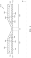
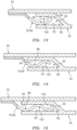
- first and the second connections 36A and 36B may accommodate (e.g., thermally induced) movement between the turbine engine component 34 and components connected thereto.
- the spring / resilient compliance of the protrusions 76 may enable differential thermal expansion between the protrusions 76 as well as the support structure 32 and the turbine engine component 34; thus, radial movement.
- the interlocking joint connections 36A and 36B may enable axial (e.g., thermally induced) movement between the components 32 and/or 76 and the turbine engine component 34; e.g., the protrusions 76 may slide within the grooves 50.
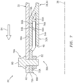
- the combustor hood 112 may also be an annular wall connected to the inner and the outer combustor walls 106 and 108.
- the combustor hood 112 has an arcuate (e.g., semi-circular) sectional geometry, which provides an annular plenum 114 axially between the hood 112 and the bulkhead 110.
- the outer combustor wall 108 is connected to the bulkhead 110 and the hood 112 at an outer j oint.
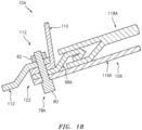
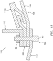
- the hood 112, the support shell 116, the first component mount 68A (e.g., its mount base) and the bulkhead 110 are arranged (e.g., sequentially) in a first stack 120.
- Each of the fasteners 78A may project through this first stack 120 to thereby secure the components 112, 116B, 68A and 110 together.
- the components 112, 116B, 68A and 110 may be arranged in other orders within the first stack 120.
- the combustor 104 is configured to direct cooling air to a portion of the projection 66A within the groove 50A.
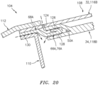
- the support shell 116A, 116B may include one or more apertures 124 (e.g., impingement apertures), which are fluidly coupled with one or more passages 126 and 128 around the protrusions 76A.
- One or more additional passages 130 may also direct cooling air between the bulkhead 110 and the first component mount 68A.
- These passages 126, 128 and/or 130 may be formed by one or more grooves in the first component mount 68A and/or one or more grooves in the adjacent components 110, 118A and 118B.
- the combustor wall 106, 108 may be configured with one or more quench or dilution apertures 138.
- Each of these quench or dilution apertures 138 may be formed at least in part by a tubular body 140 (e.g., a grommet) and extends radially through the turbine engine component 34 (e.g., the heat shield 118) and the support structure 32 (e.g., the support shell 116).
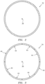
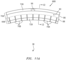
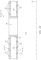
- the first portion 98 and the second portion 100 are circumferentially and axially aligned relative to the centerline 38 (e.g., centerline shown in FIGS. 1 and 7 ).
- the first portion 98 and the second portion 100 are circumferentially aligned, but may be axially offset, relative to the centerline 38 (e.g., centerline shown in FIGS. 1 and 7 ).
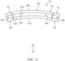
- the corrugated body may be a segmented body may up from a plurality of protrusions; e.g., circumferentially adjacent corrugations 141 may be (e.g., circumferentially) separated by a respective slit to provide the protrusions.
Landscapes
- Engineering & Computer Science (AREA)
- Chemical & Material Sciences (AREA)
- Combustion & Propulsion (AREA)
- Mechanical Engineering (AREA)
- General Engineering & Computer Science (AREA)
- Ceramic Engineering (AREA)
- Turbine Rotor Nozzle Sealing (AREA)
Claims (15)
- Chambre de combustion avec une ligne centrale, comprenant :une structure de support (32, 116) ; etun écran thermique (34, 118) s'étendant circonférentiellement autour et axialement le long de la ligne centrale (38), l'écran thermique (34, 118) comprenant un matériau céramique, et l'écran thermique (34, 118) étant monté sur la structure de support (32, 116) par une liaison par emboîtement (36) ;la liaison par emboîtement (36) comprenant une saillie (66) et une rainure (50), la saillie (66) étant configurée avec la structure de support (32, 116) et configurée comme un corps ondulé faisant saillie axialement le long de la ligne centrale dans la rainure (50), et la rainure (50) étant formée dans l'écran thermique (34, 118) radialement entre une première surface latérale de rainure (62) et une seconde surface latérale de rainure (64) ; etle corps ondulé venant en prise et étant sollicité radialement contre la première surface latérale de rainure (62) et la seconde surface latérale de rainure (64).
- Chambre de combustion selon la revendication 1, dans laquelle une surface d'extrémité de rainure (60) s'étend radialement entre la première surface latérale de rainure (62) et la seconde surface latérale de rainure (64).
- Chambre de combustion selon une quelconque revendication précédente, dans laquelle la chambre de combustion est configurée pour diriger de l'air de refroidissement à une partie de la saillie (66) à l'intérieur de la rainure (50).
- Chambre de combustion selon une quelconque revendication précédente, dans laquelle la projection (66) comprend du métal.
- Chambre de combustion selon une quelconque revendication précédente, comprenant en outre une fixation d'écran thermique (68A) comportant la saillie (66), la fixation d'écran thermique (68A) étant configurée comme un corps monolithique circulaire.
- Chambre de combustion selon une quelconque revendication précédente, comprenant en outre une ou la fixation d'écran thermique (68A) comportant la saillie (66) et une base de fixation (70A), la saillie (66) faisant saillie axialement hors de la base de fixation (70A) et dans la rainure (50).
- Chambre de combustion selon la revendication 5 ou 6, comprenant en outre :une cloison de combustion (110) ; etune hotte de chambre de combustion (112) ;la hotte de chambre de combustion (112), la cloison de chambre de combustion (110), la fixation d'écran thermique (68A) et la structure de support (32, 116) étant agencées ensemble en une pile (120) et reliées ensemble par une attache (78A) qui fait saillie radialement à travers la pile (120).
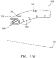
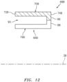
- Chambre de combustion selon une quelconque revendication précédente, comprenant en outre :une seconde fixation d'écran thermique (68B) comportant une seconde saillie (66B) et une seconde base de fixation (70B) ;la seconde fixation d'écran thermique (68B) étant configurée avec une rainure de fixation (90) s'étendant radialement entre la seconde saillie (66B) et la seconde base de fixation (70B) ; etla structure de support (32, 116) et l'écran thermique (34, 118) faisant saillie axialement dans la rainure de fixation (90).
- Chambre de combustion selon la revendication 8, dans laquelle la seconde fixation d'écran thermique (68B) est attachée à la structure de support (32, 116) par une attache (78B) s'étendant radialement à travers une fente (96) formée dans la seconde base de fixation (70B).
- Chambre de combustion selon une quelconque revendication précédente, dans laquelle :l'écran thermique(34, 118) s'étend axialement le long de la ligne centrale (38) entre une extrémité amont (46) et une extrémité aval (48) , etune liaison par emboîtement (36) est située à l'extrémité amont (46) ou à l'extrémité aval (48).
- Chambre de combustion selon une quelconque revendication, comprenant en outre un élément de positionnement (140) configuré pour positionner circonférentiellement et/ou axialement l'écran thermique (34, 118) par rapport à la structure de support (32, 116), l'élément de positionnement comprenant un corps tubulaire qui forme une ouverture de trempe.
- Chambre de combustion selon une quelconque revendication précédente, dans laquelle le corps ondulé est un corps ondulé non segmenté.
- Chambre de combustion selon l'une quelconque des revendications 1 à 11, dans laquelle le corps ondulé est un corps segmenté.
- Chambre de combustion selon la revendication 13, dans laquelle le corps ondulé comprend une pluralité de protubérances.
- Chambre de combustion selon la revendication 14, dans laquelle le corps ondulé comprend une pluralité d'ondulations (141) circonférentiellement adjacentes séparées par une pluralité respective d'incisions pour fournir les protubérances.
Applications Claiming Priority (2)
| Application Number | Priority Date | Filing Date | Title |
|---|---|---|---|
| US16/591,841 US11215367B2 (en) | 2019-10-03 | 2019-10-03 | Mounting a ceramic component to a non-ceramic component in a gas turbine engine |
| EP20199867.1A EP3800399B1 (fr) | 2019-10-03 | 2020-10-02 | Montage d'un composant céramique sur un composant non céramique dans un moteur à turbine à gaz |
Related Parent Applications (2)
| Application Number | Title | Priority Date | Filing Date |
|---|---|---|---|
| EP20199867.1A Division-Into EP3800399B1 (fr) | 2019-10-03 | 2020-10-02 | Montage d'un composant céramique sur un composant non céramique dans un moteur à turbine à gaz |
| EP20199867.1A Division EP3800399B1 (fr) | 2019-10-03 | 2020-10-02 | Montage d'un composant céramique sur un composant non céramique dans un moteur à turbine à gaz |
Publications (2)
| Publication Number | Publication Date |
|---|---|
| EP4060237A1 EP4060237A1 (fr) | 2022-09-21 |
| EP4060237B1 true EP4060237B1 (fr) | 2023-11-29 |
Family
ID=72744661
Family Applications (2)
| Application Number | Title | Priority Date | Filing Date |
|---|---|---|---|
| EP22172384.4A Active EP4060237B1 (fr) | 2019-10-03 | 2020-10-02 | Montage d'un composant céramique sur un composant non céramique dans une turbine à gaz |
| EP20199867.1A Active EP3800399B1 (fr) | 2019-10-03 | 2020-10-02 | Montage d'un composant céramique sur un composant non céramique dans un moteur à turbine à gaz |
Family Applications After (1)
| Application Number | Title | Priority Date | Filing Date |
|---|---|---|---|
| EP20199867.1A Active EP3800399B1 (fr) | 2019-10-03 | 2020-10-02 | Montage d'un composant céramique sur un composant non céramique dans un moteur à turbine à gaz |
Country Status (2)
| Country | Link |
|---|---|
| US (2) | US11215367B2 (fr) |
| EP (2) | EP4060237B1 (fr) |
Families Citing this family (16)
| Publication number | Priority date | Publication date | Assignee | Title |
|---|---|---|---|---|
| US11402100B2 (en) * | 2018-11-15 | 2022-08-02 | Pratt & Whitney Canada Corp. | Ring assembly for double-skin combustor liner |
| DE102019204544A1 (de) * | 2019-04-01 | 2020-10-01 | Siemens Aktiengesellschaft | Rohrbrennkammersystem und Gasturbinenanlage mit einem solchen Rohrbrennkammersystem |
| US11215367B2 (en) * | 2019-10-03 | 2022-01-04 | Raytheon Technologies Corporation | Mounting a ceramic component to a non-ceramic component in a gas turbine engine |
| DE102020203017A1 (de) * | 2020-03-10 | 2021-09-16 | Siemens Aktiengesellschaft | Brennkammer mit keramischem Hitzeschild und Dichtung |
| CN116792200A (zh) | 2022-03-16 | 2023-09-22 | 通用电气公司 | 燃烧衬套组件 |
| CN117091157B (zh) | 2022-05-13 | 2026-05-12 | 通用电气公司 | 用于耐用燃烧室衬里的板吊架结构 |
| CN117091158B (zh) | 2022-05-13 | 2026-03-06 | 通用电气公司 | 燃烧器室网状结构 |
| CN117091159A (zh) | 2022-05-13 | 2023-11-21 | 通用电气公司 | 燃烧器衬里 |
| CN117091162B (zh) | 2022-05-13 | 2026-03-27 | 通用电气公司 | 具有稀释孔结构的燃烧器 |
| CN117091161A (zh) | 2022-05-13 | 2023-11-21 | 通用电气公司 | 燃烧器衬里的中空板设计和结构 |
| US12398660B2 (en) | 2022-07-13 | 2025-08-26 | General Electric Company | Systems and methods for attachment of materials having different thermal expansion coefficients |
| US11788491B1 (en) | 2022-07-13 | 2023-10-17 | General Electric Company | Systems and methods for attachment of materials having different thermal expansion coefficients |
| GB202308411D0 (en) * | 2023-06-06 | 2023-07-19 | Rolls Royce Plc | Combustor assembly for a gas turbine engine |
| US12313261B1 (en) | 2024-04-05 | 2025-05-27 | Rtx Corporation | Combustor liner panels |
| US12270545B1 (en) | 2024-05-20 | 2025-04-08 | Rtx Corporation | T-head bolts or hollow flanged bushing with one thread or grooved end in a multi-liner arrangement |
| US12474052B1 (en) | 2024-05-20 | 2025-11-18 | Rtx Corporation | Dovetail features on panel rails or impingement sheet to hold panels |
Family Cites Families (19)
| Publication number | Priority date | Publication date | Assignee | Title |
|---|---|---|---|---|
| US4380896A (en) | 1980-09-22 | 1983-04-26 | The United States Of America As Represented By The Secretary Of The Army | Annular combustor having ceramic liner |
| US5636508A (en) | 1994-10-07 | 1997-06-10 | Solar Turbines Incorporated | Wedge edge ceramic combustor tile |
| GB2295887A (en) | 1994-12-08 | 1996-06-12 | Rolls Royce Plc | Combustor assembly |
| FR2825784B1 (fr) * | 2001-06-06 | 2003-08-29 | Snecma Moteurs | Accrochage de chambre de combustion cmc de turbomachine utilisant les trous de dilution |
| EP1701095B1 (fr) | 2005-02-07 | 2012-01-18 | Siemens Aktiengesellschaft | Ecran thermique |
| GB2432902B (en) | 2005-12-03 | 2011-01-12 | Alstom Technology Ltd | Gas turbine sub-assemblies |
| CH699309A1 (de) | 2008-08-14 | 2010-02-15 | Alstom Technology Ltd | Thermische maschine mit luftgekühlter, ringförmiger brennkammer. |
| US20100095680A1 (en) | 2008-10-22 | 2010-04-22 | Honeywell International Inc. | Dual wall structure for use in a combustor of a gas turbine engine |
| US8745989B2 (en) | 2009-04-09 | 2014-06-10 | Pratt & Whitney Canada Corp. | Reverse flow ceramic matrix composite combustor |
| US9651258B2 (en) | 2013-03-15 | 2017-05-16 | Rolls-Royce Corporation | Shell and tiled liner arrangement for a combustor |
| US10539327B2 (en) | 2013-09-11 | 2020-01-21 | United Technologies Corporation | Combustor liner |
| US9664389B2 (en) | 2013-12-12 | 2017-05-30 | United Technologies Corporation | Attachment assembly for protective panel |
| GB201501817D0 (en) | 2015-02-04 | 2015-03-18 | Rolls Royce Plc | A combustion chamber and a combustion chamber segment |
| DE102015202570A1 (de) | 2015-02-12 | 2016-08-18 | Rolls-Royce Deutschland Ltd & Co Kg | Abdichtung eines Randspalts zwischen Effusionsschindeln einer Gasturbinenbrennkammer |
| US10801729B2 (en) | 2015-07-06 | 2020-10-13 | General Electric Company | Thermally coupled CMC combustor liner |
| EP3540314B1 (fr) * | 2016-11-11 | 2023-07-12 | Kawasaki Jukogyo Kabushiki Kaisha | Chemise de chambre de combustion pour une turbine à gaz |
| US10801730B2 (en) | 2017-04-12 | 2020-10-13 | Raytheon Technologies Corporation | Combustor panel mounting systems and methods |
| DE102017206502A1 (de) | 2017-04-18 | 2018-10-18 | Siemens Aktiengesellschaft | Halteelement zum Fixieren eines Hitzeschildelements und Brennkammer mit Hitzeschild, das ein derartiges Halteelement umfasst |
| US11215367B2 (en) * | 2019-10-03 | 2022-01-04 | Raytheon Technologies Corporation | Mounting a ceramic component to a non-ceramic component in a gas turbine engine |
-
2019
- 2019-10-03 US US16/591,841 patent/US11215367B2/en active Active
-
2020
- 2020-10-02 EP EP22172384.4A patent/EP4060237B1/fr active Active
- 2020-10-02 EP EP20199867.1A patent/EP3800399B1/fr active Active
-
2022
- 2022-01-03 US US17/567,533 patent/US11725823B2/en active Active
Also Published As
| Publication number | Publication date |
|---|---|
| EP3800399A1 (fr) | 2021-04-07 |
| EP3800399B1 (fr) | 2022-06-29 |
| US20210102705A1 (en) | 2021-04-08 |
| US11215367B2 (en) | 2022-01-04 |
| EP4060237A1 (fr) | 2022-09-21 |
| US11725823B2 (en) | 2023-08-15 |
| US20220275942A1 (en) | 2022-09-01 |
Similar Documents
| Publication | Publication Date | Title |
|---|---|---|
| EP3800399B1 (fr) | Montage d'un composant céramique sur un composant non céramique dans un moteur à turbine à gaz | |
| EP2278125B1 (fr) | Aube statorique avec ressort radialement adaptable pour turbine à gaz | |
| US6347508B1 (en) | Combustor liner support and seal assembly | |
| US8534076B2 (en) | Combustor-turbine seal interface for gas turbine engine | |
| EP3077641B1 (fr) | Refroidissement d'un corps à ouverture pour un allumeur d'une paroi de chambre de combustion | |
| EP2126289B1 (fr) | Système de support de transition pour conduits de transition de combustion destiné à des moteurs à turbine | |
| EP0616113B1 (fr) | Turbine à gaz et procédé pour monter une garniture d'échantéité dans cette turbine à gaz | |
| US10487943B2 (en) | Multi-ply seal ring | |
| CA2080152A1 (fr) | Anneau de turbine basse pression | |
| US8752395B2 (en) | Combustor liner support and seal assembly | |
| US12313264B2 (en) | Coupling assembly for a turbine engine | |
| EP3904767B1 (fr) | Panneau de dome de chambre de combustion de turbine à gaz et procédé pour son assemblage | |
| EP3321587B1 (fr) | Interface non linéaire axial pour panneaux de chemise de chambre de combustion dans une chambre de combustion de turbine à gaz | |
| EP3321584B1 (fr) | Chambre de combustion de turbine à gaz avec un panneau de chemise de chambre de combustion axialment non-plan | |
| EP3916304B1 (fr) | Structure à parois multiples pour un moteur à turbine à gaz | |
| EP3832177B1 (fr) | Joint à brosse doté de poils croisés | |
| EP4276282A1 (fr) | Bouclier thermique et son procédé d'installation | |
| US10227952B2 (en) | Gas path liner for a gas turbine engine | |
| EP3309361B1 (fr) | Joint, section de moteur et moteur à turbine à gaz associés | |
| US11746726B2 (en) | Aircraft propulsion system nozzle with internal flow passage | |
| EP4678956A2 (fr) | Ensemble joint à brosse avec couvercle métallique | |
| EP4083390A1 (fr) | Ensemble joint à brosse double | |
| US20260015947A1 (en) | Brush seal assembly with metal clip | |
| EP4474706B1 (fr) | Ensemble chambre de combustion pour moteur à turbine à gaz |
Legal Events
| Date | Code | Title | Description |
|---|---|---|---|
| PUAI | Public reference made under article 153(3) epc to a published international application that has entered the european phase |
Free format text: ORIGINAL CODE: 0009012 |
|
| STAA | Information on the status of an ep patent application or granted ep patent |
Free format text: STATUS: THE APPLICATION HAS BEEN PUBLISHED |
|
| AC | Divisional application: reference to earlier application |
Ref document number: 3800399 Country of ref document: EP Kind code of ref document: P |
|
| AK | Designated contracting states |
Kind code of ref document: A1 Designated state(s): AL AT BE BG CH CY CZ DE DK EE ES FI FR GB GR HR HU IE IS IT LI LT LU LV MC MK MT NL NO PL PT RO RS SE SI SK SM TR |
|
| STAA | Information on the status of an ep patent application or granted ep patent |
Free format text: STATUS: REQUEST FOR EXAMINATION WAS MADE |
|
| 17P | Request for examination filed |
Effective date: 20230320 |
|
| RBV | Designated contracting states (corrected) |
Designated state(s): AL AT BE BG CH CY CZ DE DK EE ES FI FR GB GR HR HU IE IS IT LI LT LU LV MC MK MT NL NO PL PT RO RS SE SI SK SM TR |
|
| GRAP | Despatch of communication of intention to grant a patent |
Free format text: ORIGINAL CODE: EPIDOSNIGR1 |
|
| STAA | Information on the status of an ep patent application or granted ep patent |
Free format text: STATUS: GRANT OF PATENT IS INTENDED |
|
| RIC1 | Information provided on ipc code assigned before grant |
Ipc: F23R 3/60 20060101ALI20230406BHEP Ipc: F23R 3/00 20060101AFI20230406BHEP |
|
| INTG | Intention to grant announced |
Effective date: 20230509 |
|
| GRAS | Grant fee paid |
Free format text: ORIGINAL CODE: EPIDOSNIGR3 |
|
| GRAA | (expected) grant |
Free format text: ORIGINAL CODE: 0009210 |
|
| STAA | Information on the status of an ep patent application or granted ep patent |
Free format text: STATUS: THE PATENT HAS BEEN GRANTED |
|
| RAP3 | Party data changed (applicant data changed or rights of an application transferred) |
Owner name: RTX CORPORATION |
|
| AC | Divisional application: reference to earlier application |
Ref document number: 3800399 Country of ref document: EP Kind code of ref document: P |
|
| AK | Designated contracting states |
Kind code of ref document: B1 Designated state(s): AL AT BE BG CH CY CZ DE DK EE ES FI FR GB GR HR HU IE IS IT LI LT LU LV MC MK MT NL NO PL PT RO RS SE SI SK SM TR |
|
| REG | Reference to a national code |
Ref country code: GB Ref legal event code: FG4D |
|
| REG | Reference to a national code |
Ref country code: CH Ref legal event code: EP |
|
| REG | Reference to a national code |
Ref country code: DE Ref legal event code: R096 Ref document number: 602020022136 Country of ref document: DE |
|
| REG | Reference to a national code |
Ref country code: IE Ref legal event code: FG4D |
|
| REG | Reference to a national code |
Ref country code: LT Ref legal event code: MG9D |
|
| REG | Reference to a national code |
Ref country code: NL Ref legal event code: MP Effective date: 20231129 |
|
| PG25 | Lapsed in a contracting state [announced via postgrant information from national office to epo] |
Ref country code: GR Free format text: LAPSE BECAUSE OF FAILURE TO SUBMIT A TRANSLATION OF THE DESCRIPTION OR TO PAY THE FEE WITHIN THE PRESCRIBED TIME-LIMIT Effective date: 20240301 |
|
| PG25 | Lapsed in a contracting state [announced via postgrant information from national office to epo] |
Ref country code: IS Free format text: LAPSE BECAUSE OF FAILURE TO SUBMIT A TRANSLATION OF THE DESCRIPTION OR TO PAY THE FEE WITHIN THE PRESCRIBED TIME-LIMIT Effective date: 20240329 |
|
| PG25 | Lapsed in a contracting state [announced via postgrant information from national office to epo] |
Ref country code: LT Free format text: LAPSE BECAUSE OF FAILURE TO SUBMIT A TRANSLATION OF THE DESCRIPTION OR TO PAY THE FEE WITHIN THE PRESCRIBED TIME-LIMIT Effective date: 20231129 |
|
| PG25 | Lapsed in a contracting state [announced via postgrant information from national office to epo] |
Ref country code: ES Free format text: LAPSE BECAUSE OF FAILURE TO SUBMIT A TRANSLATION OF THE DESCRIPTION OR TO PAY THE FEE WITHIN THE PRESCRIBED TIME-LIMIT Effective date: 20231129 |
|
| PG25 | Lapsed in a contracting state [announced via postgrant information from national office to epo] |
Ref country code: LT Free format text: LAPSE BECAUSE OF FAILURE TO SUBMIT A TRANSLATION OF THE DESCRIPTION OR TO PAY THE FEE WITHIN THE PRESCRIBED TIME-LIMIT Effective date: 20231129 Ref country code: IS Free format text: LAPSE BECAUSE OF FAILURE TO SUBMIT A TRANSLATION OF THE DESCRIPTION OR TO PAY THE FEE WITHIN THE PRESCRIBED TIME-LIMIT Effective date: 20240329 Ref country code: GR Free format text: LAPSE BECAUSE OF FAILURE TO SUBMIT A TRANSLATION OF THE DESCRIPTION OR TO PAY THE FEE WITHIN THE PRESCRIBED TIME-LIMIT Effective date: 20240301 Ref country code: ES Free format text: LAPSE BECAUSE OF FAILURE TO SUBMIT A TRANSLATION OF THE DESCRIPTION OR TO PAY THE FEE WITHIN THE PRESCRIBED TIME-LIMIT Effective date: 20231129 Ref country code: BG Free format text: LAPSE BECAUSE OF FAILURE TO SUBMIT A TRANSLATION OF THE DESCRIPTION OR TO PAY THE FEE WITHIN THE PRESCRIBED TIME-LIMIT Effective date: 20240229 |
|
| REG | Reference to a national code |
Ref country code: AT Ref legal event code: MK05 Ref document number: 1636486 Country of ref document: AT Kind code of ref document: T Effective date: 20231129 |
|
| PG25 | Lapsed in a contracting state [announced via postgrant information from national office to epo] |
Ref country code: NL Free format text: LAPSE BECAUSE OF FAILURE TO SUBMIT A TRANSLATION OF THE DESCRIPTION OR TO PAY THE FEE WITHIN THE PRESCRIBED TIME-LIMIT Effective date: 20231129 |
|
| PG25 | Lapsed in a contracting state [announced via postgrant information from national office to epo] |
Ref country code: SE Free format text: LAPSE BECAUSE OF FAILURE TO SUBMIT A TRANSLATION OF THE DESCRIPTION OR TO PAY THE FEE WITHIN THE PRESCRIBED TIME-LIMIT Effective date: 20231129 Ref country code: RS Free format text: LAPSE BECAUSE OF FAILURE TO SUBMIT A TRANSLATION OF THE DESCRIPTION OR TO PAY THE FEE WITHIN THE PRESCRIBED TIME-LIMIT Effective date: 20231129 Ref country code: PL Free format text: LAPSE BECAUSE OF FAILURE TO SUBMIT A TRANSLATION OF THE DESCRIPTION OR TO PAY THE FEE WITHIN THE PRESCRIBED TIME-LIMIT Effective date: 20231129 Ref country code: NO Free format text: LAPSE BECAUSE OF FAILURE TO SUBMIT A TRANSLATION OF THE DESCRIPTION OR TO PAY THE FEE WITHIN THE PRESCRIBED TIME-LIMIT Effective date: 20240229 Ref country code: NL Free format text: LAPSE BECAUSE OF FAILURE TO SUBMIT A TRANSLATION OF THE DESCRIPTION OR TO PAY THE FEE WITHIN THE PRESCRIBED TIME-LIMIT Effective date: 20231129 Ref country code: LV Free format text: LAPSE BECAUSE OF FAILURE TO SUBMIT A TRANSLATION OF THE DESCRIPTION OR TO PAY THE FEE WITHIN THE PRESCRIBED TIME-LIMIT Effective date: 20231129 Ref country code: HR Free format text: LAPSE BECAUSE OF FAILURE TO SUBMIT A TRANSLATION OF THE DESCRIPTION OR TO PAY THE FEE WITHIN THE PRESCRIBED TIME-LIMIT Effective date: 20231129 |
|
| PG25 | Lapsed in a contracting state [announced via postgrant information from national office to epo] |
Ref country code: DK Free format text: LAPSE BECAUSE OF FAILURE TO SUBMIT A TRANSLATION OF THE DESCRIPTION OR TO PAY THE FEE WITHIN THE PRESCRIBED TIME-LIMIT Effective date: 20231129 |
|
| PG25 | Lapsed in a contracting state [announced via postgrant information from national office to epo] |
Ref country code: AT Free format text: LAPSE BECAUSE OF FAILURE TO SUBMIT A TRANSLATION OF THE DESCRIPTION OR TO PAY THE FEE WITHIN THE PRESCRIBED TIME-LIMIT Effective date: 20231129 Ref country code: CZ Free format text: LAPSE BECAUSE OF FAILURE TO SUBMIT A TRANSLATION OF THE DESCRIPTION OR TO PAY THE FEE WITHIN THE PRESCRIBED TIME-LIMIT Effective date: 20231129 |
|
| PG25 | Lapsed in a contracting state [announced via postgrant information from national office to epo] |
Ref country code: SK Free format text: LAPSE BECAUSE OF FAILURE TO SUBMIT A TRANSLATION OF THE DESCRIPTION OR TO PAY THE FEE WITHIN THE PRESCRIBED TIME-LIMIT Effective date: 20231129 |
|
| PG25 | Lapsed in a contracting state [announced via postgrant information from national office to epo] |
Ref country code: SM Free format text: LAPSE BECAUSE OF FAILURE TO SUBMIT A TRANSLATION OF THE DESCRIPTION OR TO PAY THE FEE WITHIN THE PRESCRIBED TIME-LIMIT Effective date: 20231129 Ref country code: SK Free format text: LAPSE BECAUSE OF FAILURE TO SUBMIT A TRANSLATION OF THE DESCRIPTION OR TO PAY THE FEE WITHIN THE PRESCRIBED TIME-LIMIT Effective date: 20231129 Ref country code: RO Free format text: LAPSE BECAUSE OF FAILURE TO SUBMIT A TRANSLATION OF THE DESCRIPTION OR TO PAY THE FEE WITHIN THE PRESCRIBED TIME-LIMIT Effective date: 20231129 Ref country code: IT Free format text: LAPSE BECAUSE OF FAILURE TO SUBMIT A TRANSLATION OF THE DESCRIPTION OR TO PAY THE FEE WITHIN THE PRESCRIBED TIME-LIMIT Effective date: 20231129 Ref country code: EE Free format text: LAPSE BECAUSE OF FAILURE TO SUBMIT A TRANSLATION OF THE DESCRIPTION OR TO PAY THE FEE WITHIN THE PRESCRIBED TIME-LIMIT Effective date: 20231129 Ref country code: DK Free format text: LAPSE BECAUSE OF FAILURE TO SUBMIT A TRANSLATION OF THE DESCRIPTION OR TO PAY THE FEE WITHIN THE PRESCRIBED TIME-LIMIT Effective date: 20231129 Ref country code: CZ Free format text: LAPSE BECAUSE OF FAILURE TO SUBMIT A TRANSLATION OF THE DESCRIPTION OR TO PAY THE FEE WITHIN THE PRESCRIBED TIME-LIMIT Effective date: 20231129 Ref country code: AT Free format text: LAPSE BECAUSE OF FAILURE TO SUBMIT A TRANSLATION OF THE DESCRIPTION OR TO PAY THE FEE WITHIN THE PRESCRIBED TIME-LIMIT Effective date: 20231129 |
|
| PG25 | Lapsed in a contracting state [announced via postgrant information from national office to epo] |
Ref country code: PT Free format text: LAPSE BECAUSE OF FAILURE TO SUBMIT A TRANSLATION OF THE DESCRIPTION OR TO PAY THE FEE WITHIN THE PRESCRIBED TIME-LIMIT Effective date: 20240401 |
|
| PG25 | Lapsed in a contracting state [announced via postgrant information from national office to epo] |
Ref country code: PT Free format text: LAPSE BECAUSE OF FAILURE TO SUBMIT A TRANSLATION OF THE DESCRIPTION OR TO PAY THE FEE WITHIN THE PRESCRIBED TIME-LIMIT Effective date: 20240401 |
|
| REG | Reference to a national code |
Ref country code: DE Ref legal event code: R097 Ref document number: 602020022136 Country of ref document: DE |
|
| PLBE | No opposition filed within time limit |
Free format text: ORIGINAL CODE: 0009261 |
|
| STAA | Information on the status of an ep patent application or granted ep patent |
Free format text: STATUS: NO OPPOSITION FILED WITHIN TIME LIMIT |
|
| PG25 | Lapsed in a contracting state [announced via postgrant information from national office to epo] |
Ref country code: SI Free format text: LAPSE BECAUSE OF FAILURE TO SUBMIT A TRANSLATION OF THE DESCRIPTION OR TO PAY THE FEE WITHIN THE PRESCRIBED TIME-LIMIT Effective date: 20231129 |
|
| PG25 | Lapsed in a contracting state [announced via postgrant information from national office to epo] |
Ref country code: SI Free format text: LAPSE BECAUSE OF FAILURE TO SUBMIT A TRANSLATION OF THE DESCRIPTION OR TO PAY THE FEE WITHIN THE PRESCRIBED TIME-LIMIT Effective date: 20231129 |
|
| 26N | No opposition filed |
Effective date: 20240830 |
|
| REG | Reference to a national code |
Ref country code: CH Ref legal event code: PL |
|
| PG25 | Lapsed in a contracting state [announced via postgrant information from national office to epo] |
Ref country code: MC Free format text: LAPSE BECAUSE OF FAILURE TO SUBMIT A TRANSLATION OF THE DESCRIPTION OR TO PAY THE FEE WITHIN THE PRESCRIBED TIME-LIMIT Effective date: 20231129 |
|
| PG25 | Lapsed in a contracting state [announced via postgrant information from national office to epo] |
Ref country code: LU Free format text: LAPSE BECAUSE OF NON-PAYMENT OF DUE FEES Effective date: 20241002 Ref country code: BE Free format text: LAPSE BECAUSE OF NON-PAYMENT OF DUE FEES Effective date: 20241031 |
|
| PG25 | Lapsed in a contracting state [announced via postgrant information from national office to epo] |
Ref country code: CH Free format text: LAPSE BECAUSE OF NON-PAYMENT OF DUE FEES Effective date: 20241031 |
|
| REG | Reference to a national code |
Ref country code: BE Ref legal event code: MM Effective date: 20241031 |
|
| PG25 | Lapsed in a contracting state [announced via postgrant information from national office to epo] |
Ref country code: FI Free format text: LAPSE BECAUSE OF FAILURE TO SUBMIT A TRANSLATION OF THE DESCRIPTION OR TO PAY THE FEE WITHIN THE PRESCRIBED TIME-LIMIT Effective date: 20231129 |
|
| PGFP | Annual fee paid to national office [announced via postgrant information from national office to epo] |
Ref country code: GB Payment date: 20250923 Year of fee payment: 6 |
|
| PGFP | Annual fee paid to national office [announced via postgrant information from national office to epo] |
Ref country code: FR Payment date: 20250924 Year of fee payment: 6 |
|
| PG25 | Lapsed in a contracting state [announced via postgrant information from national office to epo] |
Ref country code: IE Free format text: LAPSE BECAUSE OF NON-PAYMENT OF DUE FEES Effective date: 20241002 |
|
| PGFP | Annual fee paid to national office [announced via postgrant information from national office to epo] |
Ref country code: DE Payment date: 20250923 Year of fee payment: 6 |
|
| P01 | Opt-out of the competence of the unified patent court (upc) registered |
Free format text: CASE NUMBER: UPC_APP_0018558_4060237/2025 Effective date: 20251219 |
|
| PG25 | Lapsed in a contracting state [announced via postgrant information from national office to epo] |
Ref country code: CY Free format text: LAPSE BECAUSE OF FAILURE TO SUBMIT A TRANSLATION OF THE DESCRIPTION OR TO PAY THE FEE WITHIN THE PRESCRIBED TIME-LIMIT; INVALID AB INITIO Effective date: 20201002 |
|
| PG25 | Lapsed in a contracting state [announced via postgrant information from national office to epo] |
Ref country code: HU Free format text: LAPSE BECAUSE OF FAILURE TO SUBMIT A TRANSLATION OF THE DESCRIPTION OR TO PAY THE FEE WITHIN THE PRESCRIBED TIME-LIMIT; INVALID AB INITIO Effective date: 20201002 |