EP4060257A1 - Dispositif de climatisation - Google Patents
Dispositif de climatisation Download PDFInfo
- Publication number
- EP4060257A1 EP4060257A1 EP19952846.4A EP19952846A EP4060257A1 EP 4060257 A1 EP4060257 A1 EP 4060257A1 EP 19952846 A EP19952846 A EP 19952846A EP 4060257 A1 EP4060257 A1 EP 4060257A1
- Authority
- EP
- European Patent Office
- Prior art keywords
- refrigerant
- temperature
- heat exchanger
- air conditioner
- space
- Prior art date
- Legal status (The legal status is an assumption and is not a legal conclusion. Google has not performed a legal analysis and makes no representation as to the accuracy of the status listed.)
- Withdrawn
Links
Images




Classifications
-
- F—MECHANICAL ENGINEERING; LIGHTING; HEATING; WEAPONS; BLASTING
- F25—REFRIGERATION OR COOLING; COMBINED HEATING AND REFRIGERATION SYSTEMS; HEAT PUMP SYSTEMS; MANUFACTURE OR STORAGE OF ICE; LIQUEFACTION SOLIDIFICATION OF GASES
- F25B—REFRIGERATION MACHINES, PLANTS OR SYSTEMS; COMBINED HEATING AND REFRIGERATION SYSTEMS; HEAT PUMP SYSTEMS
- F25B49/00—Arrangement or mounting of control or safety devices
- F25B49/02—Arrangement or mounting of control or safety devices for compression type machines, plants or systems
-
- F—MECHANICAL ENGINEERING; LIGHTING; HEATING; WEAPONS; BLASTING
- F25—REFRIGERATION OR COOLING; COMBINED HEATING AND REFRIGERATION SYSTEMS; HEAT PUMP SYSTEMS; MANUFACTURE OR STORAGE OF ICE; LIQUEFACTION SOLIDIFICATION OF GASES
- F25B—REFRIGERATION MACHINES, PLANTS OR SYSTEMS; COMBINED HEATING AND REFRIGERATION SYSTEMS; HEAT PUMP SYSTEMS
- F25B13/00—Compression machines, plants or systems, with reversible cycle
-
- F—MECHANICAL ENGINEERING; LIGHTING; HEATING; WEAPONS; BLASTING
- F25—REFRIGERATION OR COOLING; COMBINED HEATING AND REFRIGERATION SYSTEMS; HEAT PUMP SYSTEMS; MANUFACTURE OR STORAGE OF ICE; LIQUEFACTION SOLIDIFICATION OF GASES
- F25B—REFRIGERATION MACHINES, PLANTS OR SYSTEMS; COMBINED HEATING AND REFRIGERATION SYSTEMS; HEAT PUMP SYSTEMS
- F25B2313/00—Compression machines, plants or systems with reversible cycle not otherwise provided for
- F25B2313/031—Sensor arrangements
- F25B2313/0313—Pressure sensors near the outdoor heat exchanger
-
- F—MECHANICAL ENGINEERING; LIGHTING; HEATING; WEAPONS; BLASTING
- F25—REFRIGERATION OR COOLING; COMBINED HEATING AND REFRIGERATION SYSTEMS; HEAT PUMP SYSTEMS; MANUFACTURE OR STORAGE OF ICE; LIQUEFACTION SOLIDIFICATION OF GASES
- F25B—REFRIGERATION MACHINES, PLANTS OR SYSTEMS; COMBINED HEATING AND REFRIGERATION SYSTEMS; HEAT PUMP SYSTEMS
- F25B2313/00—Compression machines, plants or systems with reversible cycle not otherwise provided for
- F25B2313/031—Sensor arrangements
- F25B2313/0314—Temperature sensors near the indoor heat exchanger
-
- F—MECHANICAL ENGINEERING; LIGHTING; HEATING; WEAPONS; BLASTING
- F25—REFRIGERATION OR COOLING; COMBINED HEATING AND REFRIGERATION SYSTEMS; HEAT PUMP SYSTEMS; MANUFACTURE OR STORAGE OF ICE; LIQUEFACTION SOLIDIFICATION OF GASES
- F25B—REFRIGERATION MACHINES, PLANTS OR SYSTEMS; COMBINED HEATING AND REFRIGERATION SYSTEMS; HEAT PUMP SYSTEMS
- F25B2500/00—Problems to be solved
- F25B2500/19—Calculation of parameters
-
- F—MECHANICAL ENGINEERING; LIGHTING; HEATING; WEAPONS; BLASTING
- F25—REFRIGERATION OR COOLING; COMBINED HEATING AND REFRIGERATION SYSTEMS; HEAT PUMP SYSTEMS; MANUFACTURE OR STORAGE OF ICE; LIQUEFACTION SOLIDIFICATION OF GASES
- F25B—REFRIGERATION MACHINES, PLANTS OR SYSTEMS; COMBINED HEATING AND REFRIGERATION SYSTEMS; HEAT PUMP SYSTEMS
- F25B2500/00—Problems to be solved
- F25B2500/22—Preventing, detecting or repairing leaks of refrigeration fluids
- F25B2500/222—Detecting refrigerant leaks
-
- F—MECHANICAL ENGINEERING; LIGHTING; HEATING; WEAPONS; BLASTING
- F25—REFRIGERATION OR COOLING; COMBINED HEATING AND REFRIGERATION SYSTEMS; HEAT PUMP SYSTEMS; MANUFACTURE OR STORAGE OF ICE; LIQUEFACTION SOLIDIFICATION OF GASES
- F25B—REFRIGERATION MACHINES, PLANTS OR SYSTEMS; COMBINED HEATING AND REFRIGERATION SYSTEMS; HEAT PUMP SYSTEMS
- F25B2600/00—Control issues
- F25B2600/25—Control of valves
- F25B2600/2513—Expansion valves
Definitions
- the present invention relates to an air conditioner.
- the apparatus disclosed in PTL 1 includes a temperature sensor configured to detect an outside air temperature and a temperature sensor configured to detect a temperature of air subjected to heat exchange at a use-side heat exchanger. This apparatus calculates a degree of supercooling based on a difference between the temperatures detected by the two temperature sensors.
- the accuracy of the degree of supercooling calculated deteriorates if there is a difference between the temperatures detected by the two temperature sensors.
- the degree of supercooling has a small value
- the accuracy of the degree of supercooling calculated deteriorates considerably due to the difference between the temperatures detected by the two temperature sensors.
- An object of the present invention is therefore to provide an air conditioner capable of determining an operation state with high accuracy.
- An air conditioner of the present invention includes a refrigerant circuit in which a first refrigerant circulates and which has a compressor, an outdoor heat exchanger, an expansion valve, and an indoor heat exchanger annularly connected by a refrigerant pipe, a detection case arranged between the outdoor heat exchanger and the expansion valve, and a diaphragm configured to divide an internal space of the detection case into a first space and a second space.
- the first space is sealed, and a second refrigerant of the same type as the first refrigerant is sealed in the first space.
- the second space is connected to the refrigerant circuit, and the first refrigerant flows into the second space.
- the air conditioner further includes a strain sensor arranged on the diaphragm and configured to detect a difference between a pressure of the first refrigerant in the second space and a pressure of the second refrigerant in the first space, and a temperature detector configured to detect a temperature of the first refrigerant between the outdoor heat exchanger and the detection case.
- An air conditioner of the present invention includes a refrigerant circuit in which a first refrigerant circulates and which has a compressor, an outdoor heat exchanger, an expansion valve, and an indoor heat exchanger annularly connected by a refrigerant pipe, a detection case arranged between the outdoor heat exchanger and the expansion valve, and a diaphragm configured to divide an internal space of the detection case into a first space and a second space.
- the first space is sealed, and a second refrigerant of the same type as the first refrigerant is sealed in the first space.
- the second space is connected to the refrigerant circuit, and the first refrigerant flows into the second space.
- the air conditioner further includes a strain sensor arranged on the diaphragm and configured to detect a difference between a pressure of the first refrigerant in the second space and a pressure of the second refrigerant in the first space, and a temperature detector configured to detect a temperature of the first refrigerant between the indoor heat exchanger and the detection case.
- the air conditioner includes the strain sensor and the temperature detector, and thus, can determine an operation state with high accuracy.
- Fig. 1 shows the configuration of the air conditioner of the reference example and a refrigerant flow in a refrigerant circuit 100 during a cooling operation of the air conditioner.
- Refrigerant circuit 100 includes a compressor 1, a four-way valve 5, an outdoor heat exchanger 2, an expansion valve 3, and an indoor heat exchanger 4 annularly connected by a refrigerant pipe 6.
- a first refrigerant CA circulates in refrigerant circuit 100.
- Compressor 1 compresses first refrigerant CA and discharges the compressed first refrigerant CA.
- Four-way valve 5 switches a flow path of first refrigerant CA.
- first refrigerant CA discharged from compressor 1 flows to outdoor heat exchanger 2.
- first refrigerant CA discharged from compressor 1 flows to indoor heat exchanger 4.
- Outdoor heat exchanger 2 performs heat exchange between the air (hereinafter, referred to as outside air as appropriate) supplied by an outdoor blower, such as a fan, and first refrigerant CA. Outdoor heat exchanger 2 functions as a condenser during the cooling operation of the air conditioner. Outdoor heat exchanger 2 functions as an evaporator during the heating operation of the air conditioner.
- Expansion valve 3 decompresses and thus expands first refrigerant CA.
- Expansion valve 3 is, for example, a valve with a controllable degree of opening, such as an electronic expansion valve.
- Indoor heat exchanger 4 performs heat exchange between the air supplied by an indoor blower, such as a fan, and first refrigerant CA. Indoor heat exchanger 4 functions as an evaporator during the cooling operation of the air conditioner. Indoor heat exchanger 4 functions as a condenser during the heating operation of the air conditioner.
- Fig. 2 shows temperature sensors arranged in the vicinity of outdoor heat exchanger 2 of Fig. 1 .
- Outdoor heat exchanger 2 includes a sub-heat exchanger 2a and a sub-heat exchanger 2b. Temperature sensor 11 is arranged in the vicinity of the middle of sub-heat exchanger 2a. Temperature sensor 11 detects a condensation temperature CT of first refrigerant CA flowing through outdoor heat exchanger 2 during the cooling operation of the air conditioner. Temperature sensor 12 is arranged at the outlet for first refrigerant CA in outdoor heat exchanger 2 during the cooling operation of the air conditioner. Temperature sensor 12 detects a temperature TA of first refrigerant CA at the outlet of outdoor heat exchanger 2 during the cooling operation of the air conditioner.
- a degree of supercooling SC of first refrigerant CA at the outlet of outdoor heat exchanger 2 can be determined based on a difference between condensation temperature CT of first refrigerant CA which is detected by temperature sensor 11 and temperature TA of first refrigerant CA at the outlet of outdoor heat exchanger 2 which is detected by temperature sensor 12.
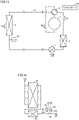
- Fig. 3 shows a configuration of an air conditioner of Embodiment 1 and a refrigerant flow in a refrigerant circuit 100 during a cooling operation of the air conditioner.
- Fig. 4 shows an arrangement of a detection case 20 of Embodiment 1.
- the air conditioner includes refrigerant circuit 100, detection case 20 connected to refrigerant circuit 100, and a controller 80.
- Refrigerant circuit 100 of Embodiment 1 is similar to refrigerant circuit 100 of the reference example, and accordingly, description thereof will not be repeated.
- Detection case 20 is arranged between outdoor heat exchanger 2 and expansion valve 3.
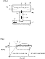
- Fig. 5 shows a configuration of detection case 20 of Embodiment 1.
- Diaphragm 23 is a displaceable thin-film member.
- First space R1 is a sealed space.
- a second refrigerant CB is sealed in first space R1.
- Second refrigerant CB is of the same type as first refrigerant CA that circulates in refrigerant circuit 100.
- Second space R2 is connected to refrigerant circuit 100 by a refrigerant pipe 7.
- First refrigerant CA that circulates in refrigerant circuit 100 flows into second space R2.
- a strain sensor GS is arranged on diaphragm 23. Although strain sensor GS is arranged within second space R2 in Fig. 5 , it may be arranged in first space R1.
- a temperature sensor KS is arranged on diaphragm 23.
- temperature sensor KS constitutes temperature detector 51.
- Temperature sensor KS detects a temperature Tq of first refrigerant CA between outdoor heat exchanger 2 and detection case 20.
- first refrigerant CA cooled by outdoor heat exchanger 2 functioning as the condenser flows into second space R2 of detection case 20.
- Fig. 6 is a p-h diagram of refrigerant circuit 100.
- LA represents an isotherm at the outside air temperature.
- LB represents an isotherm of a temperature at the outlet in outdoor heat exchanger 2 (condenser).
- LC represents an isotherm at a discharge pressure Pd of outdoor heat exchanger 2.
- the temperature of second refrigerant CB sealed in first space R1 is higher than the outside air temperature and lower than or is equal to the temperature of first refrigerant CA discharged from outdoor heat exchanger 2.
- a saturation pressure P1s at the outside air temperature a saturation pressure P2s at the temperature of first refrigerant CA discharged from outdoor heat exchanger 2
- a pressure Pv of second refrigerant CB sealed in first space R1 the following equation is established.
- a differential pressure ⁇ P between pressure Pd of first refrigerant CA in second space R2 and pressure Pv of second refrigerant CB in first space R1 occurs in diaphragm 23.
- ⁇ P Pd ⁇ Pv
- Strain sensor GS measures differential pressure ⁇ P.
- Differential pressure ⁇ P changes in accordance with degree of supercooling SC.
- degree of supercooling SC decreases, second refrigerant CB in first space R1 is heated by first refrigerant CA of high temperature which is discharged from outdoor heat exchanger 2, leading to increased Pv.
- ⁇ P decreases.
- degree of supercooling SC increases, second refrigerant CB in first space R1 is cooled by first refrigerant CA of low temperature which is discharged from outdoor heat exchanger 2, leading to decreased Pv.
- ⁇ P increases.
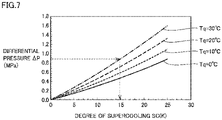
- Fig. 7 shows a relation between differential pressure ⁇ P and degree of supercooling SC at every temperature Tq in Embodiment 1.
- Controller 80 determines degree of supercooling SC of first refrigerant CA at the outlet of outdoor heat exchanger 2 based on temperature Tq of first refrigerant CA which is detected by temperature sensor KS, differential pressure ⁇ P detected by strain sensor GS, and the predetermined relation between differential pressure ⁇ P and degree of supercooling SC which corresponds to refrigerant temperature Tq.
- controller 80 identifies a table of temperature Tq of the refrigerant which is detected by temperature sensor KS from among tables showing a relation between differential pressure ⁇ P and degree of supercooling SC at every temperature Tq of the refrigerant. Controller 80 determines degree of supercooling SC corresponding to differential pressure ⁇ P detected by strain sensor GS, with reference to the identified table.
- controller 80 identifies a characteristic equation of temperature Tq of the refrigerant which is detected by temperature sensor KS from among characteristic equations showing a relation between differential pressure ⁇ P and degree of supercooling SC at every temperature Tq of the refrigerant. Controller 80 substitutes differential pressure ⁇ P detected by strain sensor GS into the determined characteristic equation, thereby calculating degree of supercooling SC.
- the characteristic equation may be, for example, a quadratic equation, or more simply, a linear equation.
- Controller 80 controls refrigerant circuit 100 based on the calculated degree of supercooling SC and condensation temperature CT.
- Controller 80 controls a degree of opening of expansion valve 3 based on condensation temperature CT of first refrigerant CA.
- Controller 80 determines whether first refrigerant CA has leaked from refrigerant circuit 100 based on degree of supercooling SC of first refrigerant CA. For example, when degree of supercooling SC of first refrigerant CA is zero, controller 80 can determine that first refrigerant CA has leaked from refrigerant circuit 100.
- Fig. 8 is a flowchart showing a control procedure of the air conditioner of Embodiment 1.
- temperature sensor KS detects temperature Tq of first refrigerant CA between outdoor heat exchanger 2 and detection case 20.
- strain sensor GS detects differential pressure ⁇ P between pressure Pd of first refrigerant CA in second space R2 of detection case 20 and pressure Pv of second refrigerant CB in first space R1 of detection case 20.
- controller 80 determines degree of supercooling SC of first refrigerant CA at the outlet of outdoor heat exchanger 2 based on temperature Tq of first refrigerant CA and differential pressure ⁇ P.
- controller 80 calculates condensation temperature CT of first refrigerant CA in outdoor heat exchanger 2 based on temperature Tq and degree of supercooling SC of first refrigerant CA.
- controller 80 determines whether first refrigerant CA has leaked from refrigerant circuit 100 based on degree of supercooling SC of first refrigerant CA.
- controller 80 controls the degree of opening of expansion valve 3 based on condensation temperature CT of first refrigerant CA.
- Fig. 9 shows a configuration of the air conditioner of Embodiment 1 and a refrigerant flow in refrigerant circuit 100 during the heating operation of the air conditioner.
- controller 80 operates as follows.
- Controller 80 does not calculate degree of supercooling SC of the refrigerant. Accordingly, differential pressure ⁇ P detected by strain sensor GS is not used by controller 80.
- Controller 80 obtains, as an evaporation temperature of first refrigerant CA in outdoor heat exchanger 2, temperature Tq of first refrigerant CA between outdoor heat exchanger 2 and detection case 20 which is detected by temperature sensor KS.
- the present embodiment calculates degree of supercooling SC using differential pressure ⁇ P applied to diaphragm 23 in detection case 20, and accordingly, can measure degree of supercooling SC with higher accuracy than when calculating a degree of supercooling using a difference between the temperatures detected by two temperature sensors 11, 12 as in the reference example.
- an error may become larger when the detected temperature has a smaller value.
- the present embodiment can detect a degree of supercooling accurately even during the operation in which an operation with a lower degree of supercooling is performed with a reduced amount of refrigerant sealed in refrigerant circuit 100.
- the present embodiment can measure degree of supercooling SC accurately, and accordingly, can detect a refrigerant leakage from the refrigerant circuit accurately.
- the present embodiment can determine an accurate degree of supercooling SC of first refrigerant CA by arranging temperature sensor KS and strain sensor GS in detection case 20. Accordingly, compared with the case when the pressure sensor for detecting a pressure of the refrigerant is arranged in the vicinity of outdoor heat exchanger 2, the present embodiment can save more space for the air conditioner in order to determine an accurate degree of supercooling SC of first refrigerant CA.
- the present embodiment can detect condensation temperature CT of first refrigerant CA even without temperature sensor 11 for measuring condensation temperature CT of first refrigerant CA as in the reference example.
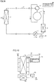
- Fig. 10 shows a temperature sensor arranged in the vicinity of outdoor heat exchanger 2 and an arrangement of detection case 20 in Embodiment 2.
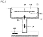
- Fig. 11 shows a configuration of detection case 20 of Embodiment 2.
- Temperature sensor 10 is arranged in the vicinity of outdoor heat exchanger 2. Temperature sensor 10 detects an outside air temperature Ta. In Embodiment 2, temperature sensor KS is not arranged on diaphragm 23.
- a computation unit 19 calculates temperature Tq of first refrigerant CA between outdoor heat exchanger 2 and detection case 20 according to the following equation from outside air temperature Ta detected by temperature sensor 10.
- Tq Ta + ⁇
- ⁇ depends on the specifications of outdoor heat exchanger 2, and can be determined as appropriate by a designer. Alternatively, ⁇ may change in accordance with a rotational speed of compressor 1. For example, ⁇ may be larger as the rotational speed of compressor 1 is higher.
- temperature sensor 10 and computation unit 19 constitute a temperature detector 52.
- Fig. 12 shows a relation between differential pressure ⁇ P and degree of supercooling SC at every temperature Tq in Embodiment 2.
- Controller 80 determines degree of supercooling SC of first refrigerant CA at the outlet of outdoor heat exchanger 2 based on temperature Tq detected by temperature detector 52, differential pressure ⁇ P detected by strain sensor GS, and the predetermined relation between differential pressure ⁇ P and degree of supercooling SC which corresponds to refrigerant temperature Tq.
- controller 80 identifies a table of temperature Tq of the refrigerant which is detected by temperature detector 52 from among tables showing a relation between differential pressure ⁇ P and degree of supercooling SC at every temperature Tq of the refrigerant. Controller 80 determines degree of supercooling SC corresponding to differential pressure ⁇ P detected by strain sensor GS, with reference to the identified table.
- controller 80 identifies a characteristic equation of temperature Tq of the refrigerant which is detected by temperature detector 52 from among the characteristic equations showing the relation between differential pressure ⁇ P and degree of supercooling SC at every temperature Tq of the refrigerant. Controller 80 substitutes differential pressure ⁇ P detected by strain sensor GS into the identified characteristic equation, thereby calculating degree of supercooling SC.
- the characteristic equation may be, for example, a quadratic equation, or more simply, a primary equation.
- controller 80 controls refrigerant circuit 100 based on the calculated degree of supercooling SC and condensation temperature CT, and controls a degree of opening of expansion valve 3 based on condensation temperature CT of first refrigerant CA.
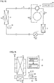
- Fig. 13 shows a configuration of an air conditioner of Embodiment 3 and a refrigerant flow in refrigerant circuit 100 during a heating operation of the air conditioner.
- Fig. 14 shows an arrangement and a configuration of detection case 20 of Embodiment 3.
- the air conditioner includes refrigerant circuit 100, detection case 20 connected to refrigerant circuit 100, and controller 80, as in Embodiment 1.
- Indoor heat exchanger 4 includes a sub-heat exchanger 4a and a sub-heat exchanger 4b.
- Detection case 20 is arranged between indoor heat exchanger 4 and expansion valve 3. An internal space of detection case 20 is divided into first space R1 and second space R2 by diaphragm 23.
- First space R1 is a sealed space.
- Second refrigerant CB is sealed in first space R1.
- a second refrigerant CB is of the same type as first refrigerant CA that circulates in refrigerant circuit 100.
- Second space R2 is connected to refrigerant circuit 100 by refrigerant pipe 7.
- First refrigerant CA that circulates in refrigerant circuit 100 flows into second space R2.
- Strain sensor GS is arranged on diaphragm 23.
- Temperature sensor KS is arranged on diaphragm 23.
- temperature sensor KS constitutes temperature detector 51.
- Temperature sensor KS detects temperature Tq of first refrigerant CA between indoor heat exchanger 4 and detection case 20.
- first refrigerant CA cooled by indoor heat exchanger 4 functioning as the condenser flows into second space R2 of detection case 20.
- differential pressure ⁇ P between pressure Pd of first refrigerant CA in second space R2 and pressure Pv of second refrigerant CB in first space R1 occurs.
- strain sensor GS measures differential pressure ⁇ P.
- Controller 80 determines degree of supercooling SC of first refrigerant CA at the outlet of indoor heat exchanger 4 based on temperature Tq of first refrigerant CA which is detected by temperature sensor KS, differential pressure ⁇ P detected by strain sensor GS, and the predetermined relation between differential pressure ⁇ P and degree of supercooling SC which corresponds to refrigerant temperature Tq.
- controller 80 identifies a table of temperature Tq of the refrigerant which is detected by temperature sensor KS from among tables showing a relation between differential pressure ⁇ P and degree of supercooling SC at every temperature Tq of the refrigerant. Controller 80 determines degree of supercooling SC corresponding to differential pressure ⁇ P detected by strain sensor GS, with reference to the identified table.
- controller 80 identifies a characteristic equation of temperature Tq of the refrigerant which is detected by temperature sensor KS from the characteristic equations showing the relation between differential pressure ⁇ P and degree of supercooling SC at every temperature Tq of the refrigerant. Controller 80 substitutes differential pressure ⁇ P detected by strain sensor GS into the identified characteristic equation, thereby calculating degree of supercooling SC.
- the characteristic equation may be, for example, a quadratic equation, or more simply, a primary equation.
- Controller 80 calculates condensation temperature CT of first refrigerant CA in indoor heat exchanger 4 according to the following equation, as in Embodiment 1.
- CT Tq + SC
- controller 80 controls refrigerant circuit 100 based on the calculated degree of supercooling SC and condensation temperature CT, and controls a degree of opening of expansion valve 3 based on condensation temperature CT of first refrigerant CA.
- Fig. 15 shows a configuration of an air conditioner of Embodiment 3 and a refrigerant flow in refrigerant circuit 100 during a cooling operation of the air conditioner.
- controller 80 operates as follows.
- Controller 80 does not calculate degree of supercooling SC of the refrigerant. Thus, differential pressure ⁇ P detected by strain sensor GS is not used by controller 80.
- Controller 80 obtains, as an evaporation temperature of first refrigerant CA in indoor heat exchanger 4, temperature Tq of first refrigerant CA between indoor heat exchanger 4 and detection case 20 which is detected by temperature sensor KS.
- Fig. 16 shows an arrangement and a configuration of detection case 20 of Embodiment 4.
- temperature sensor KS is not arranged on diaphragm 23.
- a computation unit 39 calculates temperature Tq of first refrigerant CA between indoor heat exchanger 4 and detection case 20 according to the following equation from outside air temperature Ta detected by temperature sensor 10 in the vicinity of outdoor heat exchanger 2.
- Tq Ta + ⁇
- ⁇ depends on the specifications of indoor heat exchanger 4, or may be determined as appropriate by a designer. Alternatively, ⁇ may change in accordance with a rotational speed of compressor 1. For example, ⁇ may be larger as the rotational speed of compressor 1 is higher.
- temperature sensor 10 and computation unit 39 constitute temperature detector 52.
- Controller 80 determines degree of supercooling SC of first refrigerant CA at the outlet of indoor heat exchanger 4 based on temperature Tq detected by temperature detector 52, differential pressure ⁇ P detected by strain sensor GS, and the predetermined relation between differential pressure ⁇ P and degree of supercooling SC which corresponds to refrigerant temperature Tq.
- controller 80 identifies a table of temperature Tq of the refrigerant which is detected by temperature detector 52 from among tables showing a relation between differential pressure ⁇ P and degree of supercooling SC at every temperature Tq of the refrigerant. Controller 80 determines degree of supercooling SC corresponding to differential pressure ⁇ P detected by strain sensor GS, with reference to the identified table.
- controller 80 identifies a characteristic equation of temperature Tq of the refrigerant which is detected by temperature detector 52 from among characteristic equations showing the relation between differential pressure ⁇ P and degree of supercooling SC at every temperature Tq of the refrigerant. Controller 80 substitutes differential pressure ⁇ P determined by strain sensor GS into the identified characteristic equation, thereby calculating degree of supercooling SC.
- the characteristic equation may be, for example, a quadratic equation, or more simply, a primary equation.
- controller 80 controls refrigerant circuit 100 based on the calculated degree of supercooling SC and condensation temperature CT, and controls a degree of opening of expansion valve 3 based on condensation temperature CT of first refrigerant CA.
- the present invention is not limited to the embodiments described above.
Landscapes
- Engineering & Computer Science (AREA)
- Physics & Mathematics (AREA)
- Mechanical Engineering (AREA)
- Thermal Sciences (AREA)
- General Engineering & Computer Science (AREA)
- Air Conditioning Control Device (AREA)
- Compression-Type Refrigeration Machines With Reversible Cycles (AREA)
Applications Claiming Priority (1)
| Application Number | Priority Date | Filing Date | Title |
|---|---|---|---|
| PCT/JP2019/044892 WO2021095238A1 (fr) | 2019-11-15 | 2019-11-15 | Dispositif de climatisation |
Publications (2)
| Publication Number | Publication Date |
|---|---|
| EP4060257A1 true EP4060257A1 (fr) | 2022-09-21 |
| EP4060257A4 EP4060257A4 (fr) | 2022-11-16 |
Family
ID=75912976
Family Applications (1)
| Application Number | Title | Priority Date | Filing Date |
|---|---|---|---|
| EP19952846.4A Withdrawn EP4060257A4 (fr) | 2019-11-15 | 2019-11-15 | Dispositif de climatisation |
Country Status (3)
| Country | Link |
|---|---|
| EP (1) | EP4060257A4 (fr) |
| JP (1) | JP7386886B2 (fr) |
| WO (1) | WO2021095238A1 (fr) |
Families Citing this family (1)
| Publication number | Priority date | Publication date | Assignee | Title |
|---|---|---|---|---|
| WO2023032126A1 (fr) * | 2021-09-02 | 2023-03-09 | 三菱電機株式会社 | Capteur de pression différentielle et dispositif à cycle de réfrigération équipé d'un capteur de pression différentielle |
Family Cites Families (13)
| Publication number | Priority date | Publication date | Assignee | Title |
|---|---|---|---|---|
| JP3601130B2 (ja) * | 1995-10-06 | 2004-12-15 | 株式会社デンソー | 冷凍装置 |
| JP2007085612A (ja) | 2005-09-21 | 2007-04-05 | Sanden Corp | 冷媒流量測定方法及び空気調和装置 |
| JP2008039760A (ja) | 2006-07-14 | 2008-02-21 | Denso Corp | 圧力センサ |
| JP2008249157A (ja) * | 2007-03-29 | 2008-10-16 | Saginomiya Seisakusho Inc | 可逆温度式膨張弁 |
| JP2010007994A (ja) * | 2008-06-27 | 2010-01-14 | Daikin Ind Ltd | 空気調和装置および空気調和装置の冷媒量判定方法 |
| CN102144136B (zh) | 2008-09-05 | 2013-06-19 | 丹佛斯公司 | 用于校准过热传感器的方法 |
| JP5693328B2 (ja) * | 2011-03-31 | 2015-04-01 | 中野冷機株式会社 | 冷凍装置及び冷凍装置の冷媒漏れ検知方法 |
| JP5855284B2 (ja) | 2012-12-28 | 2016-02-09 | 三菱電機株式会社 | 空気調和装置 |
| JP6238876B2 (ja) | 2014-11-21 | 2017-11-29 | 三菱電機株式会社 | 冷凍サイクル装置 |
| JP2016211832A (ja) * | 2015-04-28 | 2016-12-15 | ダイキン工業株式会社 | 利用側ユニットおよび冷凍装置 |
| WO2018159321A1 (fr) * | 2017-03-02 | 2018-09-07 | 株式会社デンソー | Module éjecteur |
| JP2019035534A (ja) | 2017-08-11 | 2019-03-07 | 株式会社デンソー | 冷凍サイクル装置 |
| JP7031482B2 (ja) * | 2018-02-08 | 2022-03-08 | 株式会社デンソー | エジェクタ式冷凍サイクル、および流量調整弁 |
-
2019
- 2019-11-15 EP EP19952846.4A patent/EP4060257A4/fr not_active Withdrawn
- 2019-11-15 JP JP2021555752A patent/JP7386886B2/ja active Active
- 2019-11-15 WO PCT/JP2019/044892 patent/WO2021095238A1/fr not_active Ceased
Also Published As
| Publication number | Publication date |
|---|---|
| EP4060257A4 (fr) | 2022-11-16 |
| JPWO2021095238A1 (fr) | 2021-05-20 |
| WO2021095238A1 (fr) | 2021-05-20 |
| JP7386886B2 (ja) | 2023-11-27 |
Similar Documents
| Publication | Publication Date | Title |
|---|---|---|
| Li et al. | Decoupling features and virtual sensors for diagnosis of faults in vapor compression air conditioners | |
| US10775084B2 (en) | System for refrigerant charge verification | |
| Li et al. | Development, evaluation, and demonstration of a virtual refrigerant charge sensor | |
| US8555703B2 (en) | Leakage diagnosis apparatus, leakage diagnosis method, and refrigeration apparatus | |
| JP7257782B2 (ja) | 空気調和システム | |
| Kim et al. | Extension of a virtual refrigerant charge sensor | |
| US20190203995A1 (en) | Refrigeration device | |
| Kim et al. | Performance evaluation of a virtual refrigerant charge sensor | |
| EP2888540B1 (fr) | Procédé d'étalonnage d'un capteur de température d'un système de compression de vapeur | |
| US7386985B2 (en) | Detection of refrigerant charge adequacy based on multiple temperature measurements | |
| EP2730863A1 (fr) | Dispositif de réfrigération et de climatisation et procédé pour commander le dispositif de réfrigération et de climatisation | |
| Li et al. | Virtual refrigerant pressure sensors for use in monitoring and fault diagnosis of vapor-compression equipment | |
| CN113175738B (zh) | 计算空调器能力能效的方法、计算机存储介质和空调器 | |
| JPWO2021250789A5 (fr) | ||
| EP4191155A1 (fr) | Climatiseur | |
| CN110914618A (zh) | 冷冻装置 | |
| CN113175737B (zh) | 计算空调器能力能效的方法、空调器和存储介质 | |
| EP3287719B1 (fr) | Dispositif à cycle frigorifique | |
| EP4060257A1 (fr) | Dispositif de climatisation | |
| EP3859224A1 (fr) | Climatiseur | |
| JP6636155B2 (ja) | 冷凍装置 | |
| KR20070017269A (ko) | 멀티 에어컨시스템의 배관점검운전방법 및 배관점검방법 | |
| CN113175734B (zh) | 计算空调器能力能效的方法、计算机存储介质和空调器 | |
| WO2022085691A1 (fr) | Climatiseur | |
| CN106196444B (zh) | 空调器蒸发温度的检测方法及系统 |
Legal Events
| Date | Code | Title | Description |
|---|---|---|---|
| STAA | Information on the status of an ep patent application or granted ep patent |
Free format text: STATUS: THE INTERNATIONAL PUBLICATION HAS BEEN MADE |
|
| PUAI | Public reference made under article 153(3) epc to a published international application that has entered the european phase |
Free format text: ORIGINAL CODE: 0009012 |
|
| STAA | Information on the status of an ep patent application or granted ep patent |
Free format text: STATUS: REQUEST FOR EXAMINATION WAS MADE |
|
| 17P | Request for examination filed |
Effective date: 20220504 |
|
| AK | Designated contracting states |
Kind code of ref document: A1 Designated state(s): AL AT BE BG CH CY CZ DE DK EE ES FI FR GB GR HR HU IE IS IT LI LT LU LV MC MK MT NL NO PL PT RO RS SE SI SK SM TR |
|
| A4 | Supplementary search report drawn up and despatched |
Effective date: 20221018 |
|
| RIC1 | Information provided on ipc code assigned before grant |
Ipc: G01L 9/00 20060101ALI20221012BHEP Ipc: F25B 13/00 20060101ALI20221012BHEP Ipc: F25B 49/02 20060101AFI20221012BHEP |
|
| DAV | Request for validation of the european patent (deleted) | ||
| DAX | Request for extension of the european patent (deleted) | ||
| STAA | Information on the status of an ep patent application or granted ep patent |
Free format text: STATUS: THE APPLICATION HAS BEEN WITHDRAWN |
|
| 18W | Application withdrawn |
Effective date: 20240830 |