EP4060430A1 - Systèmes et procédés de fonctionnement d'actifs générateurs de puissance - Google Patents
Systèmes et procédés de fonctionnement d'actifs générateurs de puissance Download PDFInfo
- Publication number
- EP4060430A1 EP4060430A1 EP22156562.5A EP22156562A EP4060430A1 EP 4060430 A1 EP4060430 A1 EP 4060430A1 EP 22156562 A EP22156562 A EP 22156562A EP 4060430 A1 EP4060430 A1 EP 4060430A1
- Authority
- EP
- European Patent Office
- Prior art keywords
- power generating
- data set
- performance
- asset
- generating asset
- Prior art date
- Legal status (The legal status is an assumption and is not a legal conclusion. Google has not performed a legal analysis and makes no representation as to the accuracy of the status listed.)
- Granted
Links
Images





Classifications
-
- H—ELECTRICITY
- H02—GENERATION; CONVERSION OR DISTRIBUTION OF ELECTRIC POWER
- H02J—ELECTRIC POWER NETWORKS; CIRCUIT ARRANGEMENTS OR SYSTEMS FOR SUPPLYING OR DISTRIBUTING ELECTRIC POWER; SYSTEMS FOR STORING ELECTRIC ENERGY
- H02J3/00—Circuit arrangements for AC mains or AC distribution networks
- H02J3/38—Arrangements for feeding a single network from two or more generators or sources in parallel; Arrangements for feeding already energised networks from additional generators or sources in parallel
- H02J3/381—Dispersed generators
-
- F—MECHANICAL ENGINEERING; LIGHTING; HEATING; WEAPONS; BLASTING
- F03—MACHINES OR ENGINES FOR LIQUIDS; WIND, SPRING, OR WEIGHT MOTORS; PRODUCING MECHANICAL POWER OR A REACTIVE PROPULSIVE THRUST, NOT OTHERWISE PROVIDED FOR
- F03D—WIND MOTORS
- F03D7/00—Controlling wind motors
- F03D7/02—Controlling wind motors the wind motors having rotation axis substantially parallel to the air flow entering the rotor
- F03D7/04—Automatic control; Regulation
- F03D7/042—Automatic control; Regulation by means of an electrical or electronic controller
- F03D7/043—Automatic control; Regulation by means of an electrical or electronic controller characterised by the type of control logic
- F03D7/046—Automatic control; Regulation by means of an electrical or electronic controller characterised by the type of control logic with learning or adaptive control, e.g. self-tuning, fuzzy logic or neural network
-
- F—MECHANICAL ENGINEERING; LIGHTING; HEATING; WEAPONS; BLASTING
- F03—MACHINES OR ENGINES FOR LIQUIDS; WIND, SPRING, OR WEIGHT MOTORS; PRODUCING MECHANICAL POWER OR A REACTIVE PROPULSIVE THRUST, NOT OTHERWISE PROVIDED FOR
- F03D—WIND MOTORS
- F03D17/00—Monitoring or testing of wind motors, e.g. diagnostics
-
- F—MECHANICAL ENGINEERING; LIGHTING; HEATING; WEAPONS; BLASTING
- F03—MACHINES OR ENGINES FOR LIQUIDS; WIND, SPRING, OR WEIGHT MOTORS; PRODUCING MECHANICAL POWER OR A REACTIVE PROPULSIVE THRUST, NOT OTHERWISE PROVIDED FOR
- F03D—WIND MOTORS
- F03D80/00—Details, components or accessories not provided for in groups F03D1/00 - F03D17/00
-
- G—PHYSICS
- G05—CONTROLLING; REGULATING
- G05B—CONTROL OR REGULATING SYSTEMS IN GENERAL; FUNCTIONAL ELEMENTS OF SUCH SYSTEMS; MONITORING OR TESTING ARRANGEMENTS FOR SUCH SYSTEMS OR ELEMENTS
- G05B13/00—Adaptive control systems, i.e. systems automatically adjusting themselves to have a performance which is optimum according to some preassigned criterion
- G05B13/02—Adaptive control systems, i.e. systems automatically adjusting themselves to have a performance which is optimum according to some preassigned criterion electric
- G05B13/0205—Adaptive control systems, i.e. systems automatically adjusting themselves to have a performance which is optimum according to some preassigned criterion electric not using a model or a simulator of the controlled system
- G05B13/026—Adaptive control systems, i.e. systems automatically adjusting themselves to have a performance which is optimum according to some preassigned criterion electric not using a model or a simulator of the controlled system using a predictor
-
- G—PHYSICS
- G05—CONTROLLING; REGULATING
- G05B—CONTROL OR REGULATING SYSTEMS IN GENERAL; FUNCTIONAL ELEMENTS OF SUCH SYSTEMS; MONITORING OR TESTING ARRANGEMENTS FOR SUCH SYSTEMS OR ELEMENTS
- G05B13/00—Adaptive control systems, i.e. systems automatically adjusting themselves to have a performance which is optimum according to some preassigned criterion
- G05B13/02—Adaptive control systems, i.e. systems automatically adjusting themselves to have a performance which is optimum according to some preassigned criterion electric
- G05B13/0265—Adaptive control systems, i.e. systems automatically adjusting themselves to have a performance which is optimum according to some preassigned criterion electric the criterion being a learning criterion
-
- G—PHYSICS
- G05—CONTROLLING; REGULATING
- G05B—CONTROL OR REGULATING SYSTEMS IN GENERAL; FUNCTIONAL ELEMENTS OF SUCH SYSTEMS; MONITORING OR TESTING ARRANGEMENTS FOR SUCH SYSTEMS OR ELEMENTS
- G05B13/00—Adaptive control systems, i.e. systems automatically adjusting themselves to have a performance which is optimum according to some preassigned criterion
- G05B13/02—Adaptive control systems, i.e. systems automatically adjusting themselves to have a performance which is optimum according to some preassigned criterion electric
- G05B13/04—Adaptive control systems, i.e. systems automatically adjusting themselves to have a performance which is optimum according to some preassigned criterion electric involving the use of models or simulators
- G05B13/048—Adaptive control systems, i.e. systems automatically adjusting themselves to have a performance which is optimum according to some preassigned criterion electric involving the use of models or simulators using a predictor
-
- H—ELECTRICITY
- H02—GENERATION; CONVERSION OR DISTRIBUTION OF ELECTRIC POWER
- H02J—ELECTRIC POWER NETWORKS; CIRCUIT ARRANGEMENTS OR SYSTEMS FOR SUPPLYING OR DISTRIBUTING ELECTRIC POWER; SYSTEMS FOR STORING ELECTRIC ENERGY
- H02J2101/00—Supply or distribution of decentralised, dispersed or local electric power generation
- H02J2101/20—Dispersed power generation using renewable energy sources
- H02J2101/22—Solar energy
-
- H—ELECTRICITY
- H02—GENERATION; CONVERSION OR DISTRIBUTION OF ELECTRIC POWER
- H02J—ELECTRIC POWER NETWORKS; CIRCUIT ARRANGEMENTS OR SYSTEMS FOR SUPPLYING OR DISTRIBUTING ELECTRIC POWER; SYSTEMS FOR STORING ELECTRIC ENERGY
- H02J2101/00—Supply or distribution of decentralised, dispersed or local electric power generation
- H02J2101/20—Dispersed power generation using renewable energy sources
- H02J2101/28—Wind energy
-
- H—ELECTRICITY
- H02—GENERATION; CONVERSION OR DISTRIBUTION OF ELECTRIC POWER
- H02J—ELECTRIC POWER NETWORKS; CIRCUIT ARRANGEMENTS OR SYSTEMS FOR SUPPLYING OR DISTRIBUTING ELECTRIC POWER; SYSTEMS FOR STORING ELECTRIC ENERGY
- H02J2103/00—Details of circuit arrangements for mains or AC distribution networks
- H02J2103/30—Simulating, planning, modelling, reliability check or computer assisted design [CAD] of electric power networks
Definitions
- the present disclosure relates in general to power generating assets, and more particularly to systems and methods for operating power generating assets by generating performance predictions based on various model-variable combinations.
- power generating assets may take a variety of forms and may include power generating assets which rely on renewable and/or nonrenewable sources of energy. Those power generating assets which rely on renewable sources of energy may generally be considered one of the cleanest, most environmentally friendly energy sources presently available.
- wind turbines have gained increased attention in this regard.
- a modern wind turbine typically includes a tower, a generator, a gearbox, a nacelle, and one or more rotor blades.
- the nacelle includes a rotor assembly coupled to the gearbox and to the generator.
- the rotor assembly and the gearbox are mounted on a bedplate support frame located within the nacelle.
- the rotor blades capture kinetic energy of wind using known airfoil principles.
- the rotor blades transmit the kinetic energy in the form of rotational energy so as to turn a shaft coupling the rotor blades to a gearbox, or if a gearbox is not used, directly to the generator.
- the generator then converts the mechanical energy to electrical energy and the electrical energy may be transmitted to a converter and/or a transformer housed within the tower and subsequently deployed to a utility grid.
- Modern wind power generation systems typically take the form of a wind farm having multiple wind turbine generators that are operable to supply power to a transmission system providing power to a power grid.
- the forecast may serve as a foundation for a production guarantee agreement.
- a forecast may be accomplished using conventional means that consider a linear relationship between a variable (e.g. wind speed) and the energy production of the power generating asset.
- the variable is often retrospectively modeled at a monthly scale. This conventional method may lead to large variations in production estimation, especially when the sample size is small. Accordingly, it may be desirable to generate more accurate forecasts of the performance of the power generating asset.
- the art is continuously seeking new and improved systems and methods for operating a power generating asset based on performance predictions for the power generating asset.
- the present disclosure is directed to a method for operating a power generating asset.
- the method may include steps a) through f).
- the method may include receiving, via a controller, at least one external data set for a sampling period from at least one source separate from the power generating asset.
- the external data set(s) may be indicative of a plurality of variables affecting a performance of the power generating asset.
- the method may also include receiving, via the controller, at least one operational data set for the power generating asset for the sampling period.
- the operational data set(s) may be indicative of the performance of the power generating asset.
- the controller may also generate a plurality of production-assessment models for the power generating asset.
- the production-assessment models may be trained via the external data set(s) and the operational data set(s) to correlate the performance of the power generating asset as a function of the plurality of variables. Additionally, the method may include generating, via the controller, a performance prediction over a predictive implementation period for each of a plurality of model-variable combinations.
- the model-variable combinations may include a plurality of combinations of each of the production-assessment models and the plurality of variables. Accordingly, the performance predictions may each include a power generation prediction and a confidence interval thereof. Further, based on one of the performance predictions, the controller may implement a control action.
- the plurality of variables may include, at least, data indicative of wind speed and wind direction at sampling intervals of the sampling period.
- the plurality of variables may also include data indicative of at least one of a temporal correlation, temperature, barometric pressure, air density, wind shear, wind veer, and turbulence intensity.
- generating the plurality of production-assessment models may also include generating, for each of the plurality of production-assessment models, a statistical algorithm or machine learning algorithm configured to determine an optimal transfer function between at least two variables of the plurality of variables and the performance of the power generating asset.
- the external data set(s) and the operational data set(s) may each be generated at a first sampling interval and a second sampling interval.
- generating the plurality of production-assessment models may also include generating a first portion of the plurality of production-assessment models based on the external data set(s) and the operational data set(s) having the first sampling interval.
- a second portion of the plurality of production-assessment models may be generated based on the external data set(s) and the operational data set(s) having the second sampling interval.
- the second sampling interval may have a higher frequency relative to the first sampling interval.
- the external data set(s) may include a modeled environmental data set indicative of a plurality of environmental variables affecting the power generating asset.
- the external data set(s) may include an environmental data set assembled from a group of power generating subsystems.
- the method may include receiving, via the controller, an indication of each of the plurality of variables from each of the power generating subsystems in the group at each sampling interval of the sampling period.
- the controller may then combine the plurality of variables received from each of the plurality of power generating subsystems in the group so as to generate a consensus environmental data set indicative of a plurality of consensus environmental variables affecting the performance of the power generating asset.
- the external data set(s) may include a plurality of environmental measurements collected by a meteorological mast.
- training the plurality of production-assessment models may also include training the plurality of production-assessment models via a plurality of environmental variables obtained via environmental sensor of the power generating asset.
- At least one of the external data set(s) and the operational data set(s) may also include at least one anomalous input for a sampling interval of the sampling period. Accordingly, the controller may generate, via an imputation algorithm, and imputed value for the anomalous input for the sampling interval.
- the power generating asset may include a wind turbine.
- the power generating asset may include a plurality of power generating subsystems.
- the power generating asset may include a wind farm, a solar power generation facility, and/or a hybrid power generating facility.
- the power generating asset may be one of a plurality of power generating assets.
- the steps a) through e) may be repeated for each of the plurality of power generating assets.
- the controller may establish a rank order for each of the plurality of power generating assets according to a desired performance prediction characteristic. The implementation of the control action may be based on the rank order.
- implementing the control action may include upgrading at least one of the plurality of power generating assets.
- an upgrade threshold may be established which corresponds to a percentage increase of the performance prediction relative to the performance of the power generating asset as indicated by the operational data set. The percentage increase may be attributable to a prospective upgrade of the power generating asset.
- the control action may include upgrading the power generating capacity of the power generating asset(s) having a percentage increase of the performance prediction which is greater than the upgrade threshold.
- implementing the control action may include implementing a diagnostic process on at least one of the plurality of power generating assets. Accordingly, a diagnostic threshold may be established which may be indicative of a percentage shortfall of the performance of the power generating asset(s), as indicated by the operational data set, relative to the performance prediction. As such, the control action may include implementing a root-cause analysis to identify a root cause of the percentage shortfall.
- the present disclosure is directed to a system for operating a power generating asset.
- the system includes at least one sensor operably coupled to the power generating asset. Additionally, the system includes a controller communicatively coupled to the sensor(s).
- the controller includes at least one processor configured to perform a plurality of operations.
- the plurality of operations may include, but are not limited to, receiving the external data set(s) and the operational data set, generating and training the plurality of production-assessment models, generating the performance predictions for the plurality of model-variable combinations, and implementing a control action based on the performance predictions as described herein.
- the plurality of operations may include any of the methods, steps and/or features described herein.
- Coupled refers to both direct coupling, fixing, or attaching, as well as indirect coupling, fixing, or attaching through one or more intermediate components or features, unless otherwise specified herein.
- the present disclosure is directed to a machine-learning, model-based analytics for operating a power generating asset.
- the present disclosure may include systems and methods which facilitate the generation of a number of different performance predictions based on multiple different model-variable combinations over a specified period.
- various machine-learning algorithms may be employed to generate a variety of different models which may emulate the performance of the power generating asset using different modeling approaches. These models may, for example, reflect linear or nonlinear relationships between the performance of the power generating asset and various variables which may affect the performance of the power generating asset.
- the various models may generate corresponding performance predictions based on various variables, combinations of variables, and/or sampling intervals. Each performance prediction may include both a power generation prediction and a confidence interval of the prediction.
- variables described herein refer to particular sets of values corresponding to a particular factor rather than particular measurements thereof.
- the variables may correspond to various environmental factors such as wind speed, wind direction, wind shear, temperature, air density, humidity level, or other similar factors.
- the models may reflect linear or nonlinear relationships between the performance of the power generating assets and the selected factor. For example, one model-variable combination may reflect the relationship between performance and wind speed, while an additional model-variable combination may reflect the relationship between performance and both the speed and direction of the wind.
- the systems and methods disclosed herein may generate and employ model-variable combinations A) through J) as illustrated below: Table 1 Combination (Relationship) Samp. Int. Variable Count A (non-linear) Hour 2x B (linear) Hour 2x C (non-linear) Day 2x D (linear) Dav 2x E (non-linear) Hour 1x F (linear) Hour 1x G (non-linear) Dav 1x H (linear) Day 1x I (non-linear) Month 1x J (linear) Month 1x
- Each of the model-variable combination A) through J) may output a different performance prediction for the power generating asset.
- Each of the different performance predictions may represent different expected power generation value and an expected range of deviation relative to the predicted value. For example, determining the performance prediction based on a two variable, non-linear model (eg., combination (A)) having an hourly sampling interval may result in the expected range of deviation being relatively small. In contrast, determining the performance prediction based on a single variable, non-linear model (e.g. combination (I)) having a monthly sampling interval may result in a greater predicted performance but also in a large expected range of deviation relative to that of combination (A).
- the model-variable combination, and corresponding performance prediction, upon which a control action is based may be selected based on certain operational considerations.
- the optimal model-variable combination may be different for one implementation strategy versus another implementation strategy.
- the various performance predictions may be employed in a variety of applications.
- the various performance predictions may be employed in the formation of production agreements/guarantees, such as related to power purchase agreements.
- production agreements/guarantees such as related to power purchase agreements.
- the various performance predictions may be employed to analyze the advisability of a contemplated upgrade to the power generating asset.
- it may be desirable to select the model-variable combination outputting the greatest predicted power generation magnitude with the smallest uncertainty.
- the various model-variable combinations may be employed to analyze a number of power generating assets.
- the resultant performance predictions for each of the power generating assets may facilitate a rank ordering of the power generating assets. Based on the rank ordering, the power generating assets employed to meet an operational objective may be selected. Additionally, the rank ordering may illuminate performance deficiencies in certain power generating assets.
- a diagnostics system may be implemented to determine the root cause of the performance deficiency relative to the remaining power generating assets to facilitate correction thereof.
- the various performance predictions may be employed to determine at least one operating mode for the power generating asset.
- the various performance predictions may be employed to determine an optimal or desired thrust limit, target rotor speed, and/or rated power.
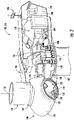
- FIG. 1 illustrates a perspective view of one embodiment of a power generating asset 100 according to the present disclosure.
- the power generating asset 100 may be configured as a wind turbine 114.
- the power generating asset 100 may, for example, be configured as a solar power generating asset, a hydroelectric plant, a fossil fuel generator, and/or a hybrid-power generating asset.
- the power generating asset 100 may be configured as a power generating facility 142.
- the power generating facility 142 may, in an embodiment, be configured as a wind farm however, in additional embodiments, the power generating facility 142 may be configured as a solar power generation facility and/or a hybrid-power generating facility.
- the power generating asset 100 may be configured as a plurality of power generating subsystems 146.
- the subsystems 148 may be configured as wind turbine(s) 114, solar power generating asset(s), hydroelectric plant(s), fossil fuel generator(s), hybrid-power generating asset(s), or combination thereof.
- the power generating asset 100 may generally include a tower 102 extending from a support surface 104, a nacelle 106, mounted on the tower 102, and a rotor 108 coupled to the nacelle 106.
- the rotor 108 may include a rotatable hub 110 and at least one rotor blade 112 coupled to, and extending outwardly from, the hub 110.
- the rotor 108 includes three rotor blades 112.
- the rotor 108 may include more or less than three rotor blades 112.
- Each rotor blade 112 may be spaced about the hub 110 to facilitate rotating the rotor 108 to enable kinetic energy to be transferred from the wind into usable mechanical energy, and subsequently, electrical energy.
- the hub 110 may be rotatably coupled to an electric generator 118 ( FIG. 2 ) positioned within the nacelle 106 to permit electrical energy to be produced.
- the power generating asset 100 may also include a controller 200.
- the controller 200 When configured as a wind turbine 114, the controller 200 may be configured as a turbine controller centralized within the nacelle 106. However, in other embodiments, the controller 200 may be located within any other component of the wind turbine 100 or at a location outside the wind turbine. Further, the controller 200 may be communicatively coupled to any number of the components of the power generating asset 100 in order to control the components. As such, the controller 200 may include a computer or other suitable processing unit. Thus, in several embodiments, the controller 200 may include suitable computer-readable instructions that, when implemented, configure the controller 200 to perform various different functions, such as receiving, transmitting and/or executing wind turbine control signals.
- the generator 118 may be coupled to the rotor 108 for producing electrical power from the rotational energy generated by the rotor 108.
- the rotor 108 may include a rotor shaft 122 coupled to the hub 110 for rotation therewith.
- the rotor shaft 122 may be rotatably supported by a main bearing 144.
- the rotor shaft 122 may, in turn, be rotatably coupled to a high-speed shaft 124 of the generator 118 through a gearbox 126 connected to a bedplate support frame 136.
- the rotor shaft 122 may provide a low-speed, high-torque input to the gearbox 126 in response to rotation of the rotor blades 112 and the hub 110.
- the gearbox 126 may then be configured to convert the low-speed, high-torque input to a high-speed, low-torque output to drive the high-speed shaft 124 and, thus, the generator 118.
- Each rotor blade 112 may also include a pitch control mechanism 120 configured to rotate each rotor blade 112 about its pitch axis 116.
- Each pitch control mechanism 120 may include a pitch drive motor 128, a pitch drive gearbox 130, and a pitch drive pinion 132.
- the pitch drive motor 128 may be coupled to the pitch drive gearbox 130 so that the pitch drive motor 128 imparts mechanical force to the pitch drive gearbox 130.
- the pitch drive gearbox 130 may be coupled to the pitch drive pinion 132 for rotation therewith.
- the pitch drive pinion 132 may, in turn, be in rotational engagement with a pitch bearing 134 coupled between the hub 110 and a corresponding rotor blade 112 such that rotation of the pitch drive pinion 132 causes rotation of the pitch bearing 134.
- rotation of the pitch drive motor 128 drives the pitch drive gearbox 130 and the pitch drive pinion 132, thereby rotating the pitch bearing 134 and the rotor blade(s) 112 about the pitch axis 116.
- the wind turbine 114 may include one or more yaw drive mechanisms 138 communicatively coupled to the controller 200, with each yaw drive mechanism(s) 138 being configured to change the angle of the nacelle 106 relative to the wind (e.g., by engaging a yaw bearing 140 of the wind turbine 114).
- the controller 200 may direct the yawing of the nacelle 106 and/or the pitching of the rotor blades 112 so as to aerodynamically orient the wind turbine 114 relative to a wind acting on the wind turbine 114, thereby facilitating power production.
- the power generating asset 100 may include at least one environmental sensor 156 for monitoring at least one environmental condition affecting the power generating asset 100.
- the environmental sensor(s) 156 may, for example, be a wind vane, an anemometer, a lidar sensor, thermometer, barometer, or any other suitable sensor. Accordingly, the environmental sensor(s) 156 may collect data indicative of wind direction, wind speed, wind shear, wind gust, wind veer, atmospheric pressure, pressure gradient and/or temperature.
- the environmental sensor(s) 156 may be mounted to the nacelle 106 at a location downwind of the rotor 108.
- the environmental sensor(s) 156 may include a network of sensors and may be positioned away from the power generating asset 100.
- the environmental sensor(s) 156 may be configured as a meteorological mast 150.
- the power generating asset 100 may include one or more operational sensors 158.
- the operational sensor(s) 158 may be configured to detect a performance of the power generating asset 100 in response to the environmental condition.
- the operational sensor(s) 158 may be configured to monitor multiple parameters associated with the performance and/or health of a component of the power generating asset 100.
- the operational sensor(s) 158 may monitor parameters associated with vibrations, audible signals, visual indications, angular positions, rotational velocities, bending moments, power consumption, power generation, temperature and/or other suitable parameters.
- the operational sensor(s) 158 may, for example, be a rotational speed sensor operably coupled to the controller 200.
- the operational sensor(s) 158 may be directed at the rotor shaft 122 of the power generating asset 100, such as the wind turbine 114.
- the operational sensor(s) 158 may gather data indicative of the rotational speed and/or rotational position of the rotor shaft 122, and thus the rotor 108 in the form of a rotor speed and/or a rotor azimuth.
- the operational sensor(s) 158 may, in an embodiment, be an analog tachometer, a direct current (DC) tachometer, an alternating current (AC) tachometer, a digital tachometer, a contact tachometer a non-contact tachometer, or a time and frequency tachometer.
- the operational sensor(s) 158 may be configured to collect data indicative of a response of the component(s) of the power generating asset 100 to the environmental condition(s) or other load.
- the operational sensor(s) 158 may be configured to monitor electrical parameters of the output of the power generating asset 100.
- the operational sensor(s) 158 may be a current sensor, voltage sensor, temperature sensors, power sensor, and/or frequency meter that monitors the electrical output of the power generating asset 100.
- the operational sensor(s) 158 may be configured as a strain gauge configured to detect a tensile load on the component, such as the rotor 108.
- the operational sensor(s) 158 may include at least one of an accelerometer, a photo-optic sensor, an acoustic sensor, a transducer, a lidar system, a vibration sensor, a force sensor, a rate sensor, a piezo sensor, a position sensor, an inclinometer, and/or a torque sensor.
- the operational sensor(s) 158 may, for example, be configured to collect sensor data indicative of at least one of a nacelle acceleration, a vibration of the tower 102, a bending of the rotor shaft 122, an acoustic signature of the power generating asset 100, an occlusion of an optical sensor due to a passage of the rotor blade 112, a rotor blade 112 discontinuity, a horizontal and vertical deflection of the rotor 108, and/or an acceleration of the rotor 108.
- the term "monitor” and variations thereof indicates that the various sensors of the power generating asset 100 may be configured to provide a direct measurement of the parameters being monitored or an indirect measurement of such parameters.
- the sensors described herein may, for example, be used to generate signals relating to the parameter being monitored, which can then be utilized by the controller 200 to determine a condition or response of the power generating asset 100.
- the power generating asset 100 is configured as a power generating facility 142 (e.g., a wind farm).
- the power generating facility may include a number of power generating subsystems 148 (e.g., wind turbines 114) as described herein.
- the power generating facility 142 may include twelve power generating subsystems 148.
- the power generating facility 142 may include any other number of power generating subsystems 148, such as less than twelve power generating subsystems 148 or greater than twelve power generating subsystems 148.
- the power generating facilities 142 may be coupled to the controller 200 and/or POI 152 via communication links 154.
- FIGS. 4-7 various aspects of multiple embodiments of a system 300 for operating the power generating asset 100 according to the present disclosure are presented.
- the system 300 may be utilized for operating the wind turbine 114 described above.
- the disclosed system 300 may be used for any other power generating asset 100 having any suitable configuration.
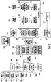
- FIG. 5 depicts steps performed in a particular order for purposes of illustration and discussion, the methods and steps described herein are not limited to any particular order or arrangement.
- One skilled in the art using the disclosures provided herein, will appreciate that various steps of the method may be omitted, rearranged, combined and/or adapted in various ways.
- the controller 200 may include one or more processor(s) 206 and associated memory device(s) 208 configured to perform a variety of computer-implemented functions (e.g., performing the methods, steps, calculations and the like and storing relevant data as disclosed herein). Additionally, the controller 200 may also include a communications module 210 to facilitate communications between the controller 200 and the power generating asset(s) 100, and components thereof.
- processor(s) 206 and associated memory device(s) 208 configured to perform a variety of computer-implemented functions (e.g., performing the methods, steps, calculations and the like and storing relevant data as disclosed herein).
- the controller 200 may also include a communications module 210 to facilitate communications between the controller 200 and the power generating asset(s) 100, and components thereof.
- the communications module 210 may include a sensor interface 212 (e.g., one or more analog-to-digital converters) to permit signals transmitted from one or more sensors, such as the environmental sensor(s) 156 and/or the operational sensor(s) 158 to be converted into signals that can be understood and processed by the processors 206.
- the sensors may be communicatively coupled to the communications module 210 using any suitable means.
- the sensors may be coupled to the sensor interface 212 via a wired connection.
- the sensors 156, 158 may be coupled to the sensor interface 212 via a wireless connection, such as by using any suitable wireless communications protocol known in the art.
- the communications module 210 may also be operably coupled to an operating state control module 214 configured to implement a control action.
- the controller 200 may be configured as an asset controller and may be integrated with the power generating asset 100.
- the controller 200 may be configured as a turbine controller, a farm controller, and/or other similar controller configured to direct the operation of the power generating asset 100.
- the controller 200 may include a distributed network of computing devices. In such an embodiment, one of the distributed computing devices may be integrated with the power generating asset 100 while an additional computing device may be located away from the power generating asset, such as at a design or manufacturing facility.
- the term "processor” refers not only to integrated circuits referred to in the art as being included in a computer, but also refers to a controller, a microcontroller, a microcomputer, a programmable logic controller (PLC), an application specific integrated circuit, and other programmable circuits.
- the memory device(s) 208 may generally comprise memory element(s) including, but not limited to, computer readable medium (e.g., random access memory (RAM)), computer readable non-volatile medium (e.g., a flash memory), a floppy disk, a compact disc-read only memory (CD-ROM), a magneto-optical disk (MOD), a digital versatile disc (DVD) and/or other suitable memory elements.
- RAM random access memory
- CD-ROM compact disc-read only memory
- MOD magneto-optical disk
- DVD digital versatile disc
- Such memory device(s) 208 may generally be configured to store suitable computer-readable instructions that, when implemented by the processor(s) 206, configure the controller 200 to perform various functions including, but not limited to, generating a plurality of production-assessment models corresponding to at least one external data set and at least one operational data set, training the production-assessment models and generating a performance prediction for each of a plurality model-variable combinations in order to implement a control action as described herein, as well as various other suitable computer-implemented functions.
- the controller 200 of the system 300 may be configured to receive at least one external data set 302 for a sampling period 304 from at least one source which is separate from the power generating asset 100.
- the external data set(s) 302 may be indicative of a plurality of variables 306.
- the plurality of variables 306 may affect a performance of the power generating asset 100.
- the controller 200 may also be configured to receive at least one operational data set 308 for the power generating asset 100 for the sampling period 304.
- the operational data set 308 may be indicative of the performance of the power generating asset 100, such as in response to the variables 306.
- the controller 200 may generate a plurality of production-assessment models 310 for the power generating asset 100.
- the controller 200 may then train (e.g. via machine learning) the plurality of production-assessment models 310 via the external and operational data sets 302, 308. Training the plurality of production-assessment models 310 may correlate the performance of the power generating asset 100 as a function of the plurality of variables 306. Once the plurality of production-assessment models 310 are trained, the controller 200 may generate a performance prediction 314 over a predictive implementation period 316 for each of a plurality of model-variable combinations 318 ( FIG. 7 ). The plurality of model-variable combinations 318 may include a plurality of combinations of each of the production assessment models 310 and the plurality of variables 306. The performance predictions 314 may each include a power generation prediction 320 and a confidence interval 322. Additionally, the controller 200 may implement a control action 324 based on one of the performance predictions 314.
- the plurality variables 306 of the external data set(s) 302 may include at least two independent variables 306. Accordingly, the performance of the power generating asset 100 (e.g. historical power production 326 ( FIG. 6 )) may be correlated as a function of the two independent variables 306. As depicted in FIG. 6 , the correlating function between the performance of the power generating asset 100 and the two independent variables 306 may be visualized as a three-dimensional plot. As the production-assessment models 310 may be trained based on the correlation of performance (e.g. historical power production 326) to the two independent variables 306, the performance prediction 314 may, thus, be based on the projected effect of the two independent variable 306 on the projected performance of the power generating asset 100. It should be appreciated that the utilization of at least two variables 306 by the controller 200 may facilitate higher fidelity performance predictions 314 than may be obtainable utilizing only a single variable 306.
- each of the plurality of model-variable combinations 318 may reflect linear or nonlinear relationships between the performance of the power generating assets and the selected factor as modeled by a particular production-assessment model 310.
- one model-variable combination 318 may reflect the relationship between performance and wind speed 328, while an additional model-variable combination 318 may reflect the relationship between performance and both the speed and direction of the wind 328, 330.
- the utilization of more than two variables 306 may further refine the correlating function, thereby increasing the fidelity of the performance prediction(s) 314. While increasing the fidelity of the performance prediction 314, the utilization of more than two variables 306 may also increase the complexity of data collection and/or analysis thereof. Accordingly, it may be desirable to balance the benefits attributable to the increase in fidelity of the performance prediction(s) 314 with the increased complexity of data collection and/or analysis thereof.
- the plurality of variables 306 of the external data set(s) 302 include both a wind speed 328 and a wind direction 330 affecting the performance of the power generating asset 100.
- the performance of the power generating asset 100 e.g., a historical power production 326) in response to both the wind speed 328 and the wind direction 330 may, thus, be reflected by the operational data set 308.
- the simultaneous correlation of both wind speed 328 and wind direction 330 to the historical performance of the power generating asset 100 may facilitate higher fidelity performance predictions 314 than may be obtainable utilizing only one of the wind speed or direction 328, 330.
- a wind turbine 114 may encounter a certain wind speed 328 from a first direction and may produce a first quantity of power. However, when the same wind speed 328 comes from a different direction, the wind turbine 114 may produce a second, lesser quantity of power. This may, for example, be attributable to a disturbed airflow (such as a wake effect), an obstruction, an operating limit, and/or other condition. Accordingly, developing the performance prediction 314 based on only one of wind speed or direction 328, 330 may reduce the accuracy of and/or confidence in the performance prediction(s) 314 relative to a performance prediction 314 based on at least wind speed 328 and wind direction 330.
- the plurality variables 306 may also include at least one additional variable 306 which may further define the correlation of the performance of the power generating asset 100 to the external data set(s) 302. Accordingly, in an embodiment, the plurality of variables 306 may include at least three variables 306. For example, the plurality variables 306 may include the wind speed 328, the wind direction 330, and at least one additional variable 306. In an embodiment, the additional variable 306 may be a temporal correlation 332. The temporal correlation 332 may relate the performance of the power generating asset 100 to a defined time period, such as day, night, a season, or other similar measure.
- the temporal correlation 332 may illuminate a change in the performance of the power generating asset 100 during certain periods of the year, such as seasons during which increased wind velocities may be experienced.
- the additional variable(s) 306 may include a measure of wind shear 334, turbulence intensity 336 and/or measures of other variables (e.g. temperature, air pressure, air density, humidity levels, wind sheer, wind veer, turbulence intensity, etc.) which may affect the performance of the power generating asset 100.
- the sampling period 304 may include a plurality of sampling intervals at which the data comprising the external data set(s) 302 and/or the operational data set 308 may be collected.
- the sampling interval may be selected so as to develop external and/or operational data sets 302, 308 having a sufficient number of historical data points to support the training of the production-assessment models 310.
- the sampling intervals may, for example, be established with a monthly frequency.
- each sampling intervals may correspond to 24 hours.
- the sampling interval may have a duration of less than or equal to 60 minutes (e.g., a sampling interval of 10 minutes).
- the external and operational data sets 302, 308 may each be generated at a first sampling interval 338 and at least at a second sampling interval 340.
- the second sampling interval 340 may, in an embodiment, have a higher frequency/sampling rate relative to the first sampling interval 338.
- the first sampling interval 338 may correspond to a monthly sampling interval
- the second sampling interval 340 may correspond to a daily sampling interval
- a third sampling interval may correspond to an hourly sampling interval, with an external and an operational data set 302, 308 corresponding to each of the sampling intervals.
- the various production-assessment models 310 may be trained on the corresponding variables 306 at each of the sampling intervals (as depicted by Table 1).
- a first portion 342 of the production-assessment models 310 may be generated based on the external data set 302 and the operational data set 308 having the first sampling interval 338.
- a second portion 344 of the production-assessment models 310 may be generated based on the external data set(s) 302 and the operational data set 308 having the second sampling interval 340.
- the external data set(s) 302 and/or the operational data set(s) 308 may include at least one anomalous input for a sampling interval of the sampling period 304.
- the anomalous input may be a quality issue with a portion of the external and/or operational data sets 302, 308.
- the anomalous input may result from an inaccurate anemometer wind speed measurement, a curtailed operating condition of the power generating asset 100, icing of a rotor blade 112, and/or missing power production data for a sampling interval.
- the controller 200 may, in an embodiment, employ an imputation algorithm to generate an imputed value 346 for the anomalous input for the sampling interval.
- the controller 200 may utilize the operational data set 308 to learn the power production characteristics (e.g., a power curve) of a power generating asset 100. The controller may then utilize the learned characteristic to estimate/impute a power production value for the missing power production data.
- the external data set(s) 302 may include a modeled environmental data set.
- the modeled environmental data set may be indicative of a plurality of environmental variables which may affect the power generating asset 100.
- the external data set(s) 302 may be developed from environmental models, such as the Modern-Era Retrospective analysis for Research and Applications, Version 2 (MERRA-2) model or other similar reanalysis approaches.
- the external data set(s) 302 may include a plurality of environmental measurements collected by at least one meteorological mast 150 (e.g., a met mast).
- the meteorological mast(s) 150 may be installed in the vicinity of the power generating asset 100 and may serve as a mounting location for the environmental sensor(s) 156. Accordingly, the meteorological mast(s) 150 may include an anemometer, a weathervane, a barometer, a hydrometer, a thermometer, and/or other similar meteorological instrumentation configured to collect measurements indicative of the variables 306 affecting the performance of the power generating asset 100.
- the external data set(s) 302 may include an environmental data set assembled from a group of power generating subsystems 148 of the power generating asset 100.
- the controller 200 may receive an indication of each of the plurality of variables 306 from each of the power generating subsystems 148 in the group at each sampling interval of the sampling period 304. The controller may then combine the plurality of variables 306 received from each of the power generating subsystems 148 to generate a consensus environmental data set indicative of a plurality of consensus environmental variables 306 affecting the performance of the power generating asset 100.
- the controller 200 may receive a yaw setpoint indication from each of the wind turbines 114.
- the combined yaw setpoints of a designated group of wind turbines 114 may provide a consensus indication of the prevailing wind direction 330 affecting the power generating asset 100.
- the utilization of data obtained from a group of power generating subsystems 148 to determine an environmental condition affecting the power generating asset 100 is more fully described in U.S. patent application No.: 17/027,789 .
- U.S. patent application No.: 17/027,789 entitled “Systems and Methods for Controlling a Wind Turbine” filed September 22, 2020 is incorporated herein by reference in its entirety for all purposes.
- the controller 200 may generate and train the plurality of production-assessment models 310 for the power generating asset 100.
- Generating the production-assessment models 310 may, in an embodiment, include generating a statistical algorithm or machine learning algorithm for each of the plurality of production-assessment models 310, and training the algorithms via the external and operational data sets 302, 308.
- the statistical algorithm or machine learning algorithm may be configured to determine an optimal transfer function 341 between at least two variables 306 of the plurality of variables 306 and the performance of the power generating asset 100 as reflected by the operational data set(s) 308.
- a stepwise regression may be utilized to generate and train at least one of the production-assessment models 310.
- stepwise regression adds or removes features one at a time in an attempt to get the best regression model without over fitting.
- stepwise regression typically has two variants including forward and backward regression, both of which are within the scope and spirit of the invention.
- forward stepwise regression is a step-by-step process of building a model by successive addition of predictive variables. At each step, models with and without a potential predictor variable are compared, and the larger model is accepted only if it leads to a significantly better fit to the data.
- backward stepwise regression starts with a model with all predictors and removes terms that are not statistically significant in terms of modeling the response variable.
- Another statistical method which may be employed in an embodiment to generate and train at least one of the production-assessment models 310 may be a least absolute shrinkage and selection operator (LASSO) algorithm.
- LASSO least absolute shrinkage and selection operator
- a LASSO algorithm minimizes the negative log-likelihood subject to a constraint that the sum of the absolute value of the coefficients is smaller than a constant.
- M5 Prime M5 Prime
- stepwise regression may produce a single global linear model for the data
- tree-based regression algorithms may perform logical tests on features to form a tree structure.
- the M5P algorithm utilizes a linear regression model at each node of the tree, providing more specialized models.
- other machine learning methods which may be employed to generate and train the various production-assessment models 310 may include, for example, Gaussian Process Models, Random Forest Models, Neural Network, Deep Neural Networks and/or Support Vector Machines.
- GAM Generalized Additive Model
- the controller 200 may develop the one or more of production-assessment models 310.
- the GAM may implement a bagging and boosting approach.
- the GAM may implement a spline method. It should be appreciated that the system 300 may employ combinations of the statistical algorithms or machine learning algorithms disclosed herein in order to determine the model-variable combination 318 which generates the most desirable performance prediction 314 for a given operating objective.
- the controller 200 may, in an embodiment, be configured to receive a plurality of environmental variables 348 from the environmental sensor 156 of the power generating asset 100.
- the plurality of environmental variables 348 as monitored by the environmental sensor 156 of the power generating asset 100 may then be incorporated by the controller 200 into the training of the production-assessment models 310.
- the perception of the plurality of environmental variable 348 by the power generating asset 100 may affect various setpoints of the power generating asset 100, and therefore the performance of the power generating asset 100.
- the inclusion of the plurality of environmental variables 348 as monitored by the power generating asset 100 in the training of the production-assessment models 310 may facilitate the refinement of the correlating function.
- the production-assessment models 310 may be tested to determine the accuracy of the production-assessment models 310.
- a portion of the external and operational data sets 302, 308 corresponding to a specific sampling period may be excluded from the data sets employed in the training of the production-assessment models 310.
- the withheld portion of the external data set(s) 302 may then be employed by the controller 200 to model the performance of the power generating asset 100 under the conditions indicated by the withheld portion.
- the modeled performance may then be compared to the withheld portion of the operational data set(s) 308 to determine the accuracy of the production-assessment model 310.
- each of the model-variable combinations 318 may generate a different performance prediction 314 for the power generating asset 100.
- Each performance prediction 314 may have a difference in the power generation prediction 320 and/or the confidence interval 322.
- the differences in the performance predictions 314 may be attributable to modeling differences, variable selection, and/or the sampling intervals of the sampling period 304. Accordingly, an optimal model-variable combination 318 may be selected from the plurality of model-variable combinations 318 based on operational objectives and/or operational constraints of the power generating asset 100.
- the optimal model-variable combination 318 may be the model-variable combination 318 having the narrowest confidence interval 322.
- the confidence interval 322 may indicate that a range of deviation between the power generation prediction 320 and an actual power production for the power generating asset 100 may be smaller than may be achievable using other model-variable combinations 318.
- the selected optimal model-variable combination 318 may indicate that the actual power production of the power generating asset may not deviate significantly from the power generation prediction 320.
- the power generation prediction 320 may be relied upon to form an energy guarantee agreement.
- the performance predictions 314 may be employed to determine whether sufficient benefit may be realized from an upgrade to the power generating asset 100 to justify a cost of the upgrade.
- the optimal model-variable combination 318 may be the model-variable combination 318 having the greatest power generation prediction 320 and the narrowest confidence interval 322.
- the optimal model-variable combination 318 may, in such an embodiment, not be the model-variable combination 318 having the greatest overall power generation prediction 320 if the prediction is accompanied by a relatively wide confidence interval 322.
- the controller 200 may implement at least one control action 324 based on the performance predictions 314.
- the control action(s) 324 may include generating an alert.
- the generation of the alert may facilitate the scheduling of a maintenance event in order to address a performance prediction 314 which is less than an expected value and/or includes a significant degree of potential variability.
- the alert may include an auditory signal, a visual signal, a notification, a system input, and/or any other system which may identify a potential for the power generating asset 100 to fail to meet a performance expectation and therefore a potential fault within the power generating asset 100.
- control action(s) 324 as described herein may further include any suitable command or constraint by the controller 200.
- the control action(s) 324 may include temporarily de-rating the power generating asset 100.
- the control action(s) 324 may include limiting an operation of at least one component of the power generating asset 100.
- the control action(s) 324 may limit a pitching of a rotor blade 112 and/or a yawing of the nacelle 106 of the wind turbine 114.
- the power generating asset may be one of a plurality of power generating assets 160.
- the power generating asset 100 may be one of several wind farms with each wind farm constituting a different power generating asset 100.
- the power generating asset 100 may be a plurality of power generating subsystems 146 corresponding to a portion of a power generating facility (e.g., a wind farm) so that the power generating facility may include a number of pluralities of power generating subsystems 146 (e.g. various groupings of power generating subsystems 148).
- the methods disclosed herein may be repeated for each power generating asset 100 of the plurality of power generating assets 160. Repeating the steps of the methods disclosed herein for each power generating asset 100 may generate performance predictions 314 for each power generating asset 100 of the plurality of power generating assets 160.
- the controller 200 may then, in an embodiment, establish a rank order 350 for each of the plurality of power generating assets 160 according to a desired performance prediction characteristic.
- the desired performance prediction characteristic may correspond to the power generation prediction 320, the confidence interval 322, or a combination thereof.
- the implementation of the control action(s) 324 may be based on the rank order 350.
- the rank order 350 may indicate which power generating asset 100 of the plurality of power generating assets 160 may be most likely to satisfy a power production guarantee. Therefore, the identified power generating asset, which may be the highest ranked power generating asset, may be preferentially employed relative to the remaining plurality of power generating assets 160 in an effort to satisfy the required power production.
- implementing the control action(s) 324 may involve upgrading at least one portion of the plurality of power generating assets 160.
- the production-assessment models 310 may be amended/modified to account for the proposed modifications/upgrades to the power generating asset 100. Therefore, the performance predictions 314 may reflect the expected performance of each of the plurality of power generating assets 160, should the contemplated upgrade be executed.
- the determination of the power generating assets 100 to be upgraded may be based, at least in part, on the rank order 350 of the performance predictions 314 reflecting the expected performances.
- an upgrade threshold 352 may be established.
- the upgrade threshold 352 may correspond to a percentage increase in the performance prediction 314 relative to a current performance (e.g., power production) of the power generating asset 100 as indicated by the operational data set(s) 308.
- the percentage increase may be attributable to a perspective upgrade of the power generating asset 100.
- an increase in predicted performance which is greater than the upgrade threshold 352 may be identified.
- the increase in the predicted performance is greater than the upgrade threshold 352
- the corresponding power generating asset(s) 100 may, as depicted at 356, be upgraded.
- implementing the control action(s) 324 may include implementing a diagnostic process on at least one of the plurality of power generating assets 160.
- a diagnostic threshold 358 may be established.
- the diagnostic threshold 358 may be indicative of a percentage shortfall of the performance of the power generating asset 100 relative to performance predictions 314 for the remainder of the plurality of power generating assets 160.
- the percentage shortfall may indicate a percentage shortfall relative to a median, or other statistical measure, of the performance predictions 314 for the plurality of power generating assets 160. Accordingly, as depicted at 360, a predicted percentage of performance shortfall greater than the threshold may be detected.
- a root-cause analysis 362 may be implemented.
- the root-cause analysis 362 may seek to identify a root cause of the percentage shortfall.
- Such a root cause analysis 362 is more fully described in U.S. patent application No.: 17/032,218 .
- U.S. patent application No.: 17/032,218 entitled “Systems and Methods for Operating a Power Generating Asset” filed September 25, 2020 is incorporated herein by reference in its entirety for all purposes.
Landscapes
- Engineering & Computer Science (AREA)
- Artificial Intelligence (AREA)
- Physics & Mathematics (AREA)
- Software Systems (AREA)
- Evolutionary Computation (AREA)
- Computer Vision & Pattern Recognition (AREA)
- Health & Medical Sciences (AREA)
- Automation & Control Theory (AREA)
- General Physics & Mathematics (AREA)
- Medical Informatics (AREA)
- Life Sciences & Earth Sciences (AREA)
- Sustainable Development (AREA)
- Sustainable Energy (AREA)
- Mechanical Engineering (AREA)
- Chemical & Material Sciences (AREA)
- Combustion & Propulsion (AREA)
- General Engineering & Computer Science (AREA)
- Power Engineering (AREA)
- Fuzzy Systems (AREA)
- Mathematical Physics (AREA)
- Wind Motors (AREA)
Applications Claiming Priority (1)
| Application Number | Priority Date | Filing Date | Title |
|---|---|---|---|
| US17/206,331 US11728654B2 (en) | 2021-03-19 | 2021-03-19 | Systems and methods for operating power generating assets |
Publications (2)
| Publication Number | Publication Date |
|---|---|
| EP4060430A1 true EP4060430A1 (fr) | 2022-09-21 |
| EP4060430B1 EP4060430B1 (fr) | 2024-08-28 |
Family
ID=80683017
Family Applications (1)
| Application Number | Title | Priority Date | Filing Date |
|---|---|---|---|
| EP22156562.5A Active EP4060430B1 (fr) | 2021-03-19 | 2022-02-14 | Systèmes et procédés de fonctionnement d'actifs générateurs de puissance |
Country Status (5)
| Country | Link |
|---|---|
| US (1) | US11728654B2 (fr) |
| EP (1) | EP4060430B1 (fr) |
| CN (1) | CN115111115A (fr) |
| DK (1) | DK4060430T3 (fr) |
| ES (1) | ES2998336T3 (fr) |
Families Citing this family (2)
| Publication number | Priority date | Publication date | Assignee | Title |
|---|---|---|---|---|
| US11761427B2 (en) * | 2021-06-29 | 2023-09-19 | Aspentech Corporation | Method and system for building prescriptive analytics to prevent wind turbine failures |
| US20250245526A1 (en) * | 2024-01-26 | 2025-07-31 | Siemens Aktiengesellschaft | Method for generating a prediction system for a machine |
Citations (4)
| Publication number | Priority date | Publication date | Assignee | Title |
|---|---|---|---|---|
| EP2688015A1 (fr) * | 2012-07-20 | 2014-01-22 | Tata Consultancy Services Limited | Procédé et système de prévision adaptative des ressources d'énergie |
| US20160371405A1 (en) * | 2015-06-19 | 2016-12-22 | General Electric Company | Systems and Methods of Forecasting Power Plant Performance |
| US20180204095A1 (en) * | 2017-01-18 | 2018-07-19 | General Electric Company | Systems and methods to evaluate and reduce outages in power plants |
| US20210061673A1 (en) * | 2019-08-26 | 2021-03-04 | Bishop Ascendant, Inc. | Modules of a modular support system |
Family Cites Families (74)
| Publication number | Priority date | Publication date | Assignee | Title |
|---|---|---|---|---|
| US2837984A (en) | 1956-01-09 | 1958-06-10 | Donald D Klotz | Limestone type tennis court |
| SE517970C2 (sv) | 2000-07-20 | 2002-08-13 | Volvo Articulated Haulers Ab | Förfarande för att uppskatta en livslängdsreducerande skada på ett i drift belastat objekt,jämte datorprogramprodukt |
| US6975925B1 (en) | 2002-03-19 | 2005-12-13 | Windlynx Systems, B.V. | Forecasting an energy output of a wind farm |
| US6922640B2 (en) | 2002-12-18 | 2005-07-26 | Sulzer Markets And Technology Ag | Method for the estimating of the residual service life of an apparatus |
| DE10327344A1 (de) | 2003-06-16 | 2005-01-27 | Repower Systems Ag | Windenergieanlage |
| US7149657B2 (en) | 2003-06-23 | 2006-12-12 | General Electric Company | Method, system and computer product for estimating a remaining equipment life |
| US7448853B2 (en) | 2005-04-12 | 2008-11-11 | Sundyne Corporation | System and method of determining centrifugal turbomachinery remaining life |
| US8649911B2 (en) | 2005-06-03 | 2014-02-11 | General Electric Company | System and method for operating a wind farm under high wind speed conditions |
| US7395188B1 (en) | 2006-12-07 | 2008-07-01 | General Electric Company | System and method for equipment life estimation |
| US7725293B2 (en) | 2006-12-07 | 2010-05-25 | General Electric Company | System and method for equipment remaining life estimation |
| US7889840B2 (en) | 2007-01-10 | 2011-02-15 | The United States Of America As Represented By The Secretary Of The Navy | System and method for predicting material fatigue and damage |
| US7548830B2 (en) | 2007-02-23 | 2009-06-16 | General Electric Company | System and method for equipment remaining life estimation |
| EP2053241A1 (fr) | 2007-10-24 | 2009-04-29 | Ecotecnia Energias Renovables S.L. | Procédé pour déterminer les dommages dus à la fatigue dans un groupe de transmission d'éolienne |
| JP5244502B2 (ja) | 2008-08-25 | 2013-07-24 | 三菱重工業株式会社 | 風車の運転制限調整装置及び方法並びにプログラム |
| DE102009027981B4 (de) | 2009-07-23 | 2011-04-28 | Suzlon Energy Gmbh | Verfahren zum Betreiben einer an einem Stromnetz angeschlossenen Windturbine sowie zur Durchführung des Verfahrens geeignete Windturbine |
| US20110020122A1 (en) | 2009-07-24 | 2011-01-27 | Honeywell International Inc. | Integrated condition based maintenance system for wind turbines |
| US8451134B2 (en) | 2009-07-24 | 2013-05-28 | Honeywell International Inc. | Wind turbine generator fault diagnostic and prognostic device and method |
| US7895016B2 (en) | 2009-08-31 | 2011-02-22 | General Electric Company | System and method for wind turbine health management |
| EP2502174B1 (fr) | 2009-11-16 | 2018-06-13 | Simmonds Precision Products, Inc. | Système d'acquisition de données pour maintenance conditionnelle |
| GB2476506A (en) | 2009-12-23 | 2011-06-29 | Vestas Wind Sys As | Method And Apparatus Protecting Wind Turbines From Low Cycle Fatigue Damage |
| ES2573127T3 (es) | 2010-02-05 | 2016-06-06 | Vestas Wind Systems A/S | Método para hacer funcionar una central de energía eólica |
| US8924162B2 (en) | 2010-05-13 | 2014-12-30 | University Of Cincinnati | Turbine-to-turbine prognostics technique for wind farms |
| CA2732251A1 (fr) | 2010-05-28 | 2011-11-28 | Mitsubishi Heavy Industries, Ltd. | Dispositif et procede de controle et centrale eolienne ainsi equipee |
| US8554386B2 (en) | 2010-06-02 | 2013-10-08 | Serge Rutman | System and method for self-powered communications networks |
| GB2484266A (en) | 2010-09-30 | 2012-04-11 | Vestas Wind Sys As | Over-rating control of a wind turbine power plant |
| GB2491548A (en) | 2010-09-30 | 2012-12-12 | Vestas Wind Sys As | Over-rating control of a wind turbine power plant |
| US8150641B2 (en) * | 2010-12-06 | 2012-04-03 | General Electric Company | System, device, and method for estimating possible power output of wind turbines |
| US8930299B2 (en) | 2010-12-15 | 2015-01-06 | Vaisala, Inc. | Systems and methods for wind forecasting and grid management |
| US9074468B1 (en) | 2011-01-27 | 2015-07-07 | Selman and Associates, Ltd. | Method for real-time streaming of well logging data with self-aligning satellites |
| US8249852B2 (en) | 2011-05-19 | 2012-08-21 | General Electric Company | Condition monitoring of windturbines |
| US9194376B2 (en) | 2011-05-24 | 2015-11-24 | General Electric Company | System and method for estimating remaining life for a device |
| DK201170539A (en) | 2011-09-30 | 2013-03-31 | Vestas Wind Sys As | Control of wind turbines |
| GB201200491D0 (en) | 2012-01-12 | 2012-02-22 | Romax Technology Ltd | Method for operating a wind turbine generator |
| JP5567044B2 (ja) | 2012-02-21 | 2014-08-06 | 三菱重工業株式会社 | ウインドファームの運転方法及びウインドファームの運転制御システム |
| US20130320674A1 (en) | 2012-05-30 | 2013-12-05 | Clipper Windpower, Llc | Net Present Value Optimized Wind Turbine Operation |
| US9395270B2 (en) | 2012-10-19 | 2016-07-19 | Florida Power & Light Company | Method and system for monitoring rotor blades in combustion turbine engine |
| US10181101B2 (en) | 2012-12-17 | 2019-01-15 | Arizona Board Of Regents On Behalf Of Arizona State University | Support vector machine enhanced models for short-term wind farm generation forecasting |
| EP2956831B1 (fr) | 2013-02-15 | 2019-08-14 | Aktiebolaget SKF | Système de surveillance d'état et procédé de création et d'actualisation d'informations de service |
| US20140324495A1 (en) | 2013-02-22 | 2014-10-30 | Vestas Wind Systems A/S | Wind turbine maintenance optimizer |
| US20140288855A1 (en) | 2013-03-20 | 2014-09-25 | United Technologies Corporation | Temporary Uprating of Wind Turbines to Maximize Power Output |
| AT514680A2 (de) | 2013-08-05 | 2015-02-15 | Uptime Engineering Gmbh | Prozess zur Optimierung der Wartung technischer Systeme |
| JP5984791B2 (ja) | 2013-12-20 | 2016-09-06 | 三菱重工業株式会社 | 風力発電装置のモニタリングシステム及びモニタリング方法 |
| CN106164477B (zh) | 2014-03-12 | 2019-10-18 | 维斯塔斯风力系统集团公司 | 具有过载控制的风力涡轮机 |
| US20150278405A1 (en) * | 2014-03-31 | 2015-10-01 | Vestas Wind Systems A/S | Method for evaluating a performance prediction for a wind farm |
| DE102014207612A1 (de) | 2014-04-23 | 2015-10-29 | Senvion Gmbh | Windenergieanlagen-Diagnosevorrichtung für Generatorkomponenten |
| US9551322B2 (en) * | 2014-04-29 | 2017-01-24 | General Electric Company | Systems and methods for optimizing operation of a wind farm |
| US9035479B1 (en) | 2014-07-11 | 2015-05-19 | Wind Stream Properties, Llc | Turbine controller for optimizing economic present value of the turbine |
| WO2016023554A1 (fr) | 2014-08-15 | 2016-02-18 | Vestas Wind Systems A/S | Augmentation de la puissance nominale de turbine à l'aide d'une prédiction de turbulence |
| EP3221579B1 (fr) | 2014-11-18 | 2023-03-29 | Hitachi Energy Switzerland AG | Procédé et système de contrôle d'état de turbine éolienne |
| EP3035140B1 (fr) | 2014-12-19 | 2018-09-12 | Rolls-Royce Deutschland Ltd & Co KG | Procédé et système de surveillance de l'état d'un équipement |
| CN104915747B (zh) * | 2015-02-03 | 2019-02-01 | 远景能源(江苏)有限公司 | 一种发电机组的发电性能评估方法及设备 |
| US9859787B2 (en) | 2015-04-22 | 2018-01-02 | Ge Energy Power Conversion Technology Limited | Life of a semiconductor by reducing temperature changes therein via reactive power |
| EP3303834B1 (fr) | 2015-05-27 | 2020-09-16 | Vestas Wind Systems A/S | Procédé de commande d'une éolienne prenant en compte une valeur de fatigue |
| EP3317523B1 (fr) | 2015-06-30 | 2020-09-23 | Vestas Wind Systems A/S | Procédés et systèmes de génération de programmes de commande d'éolienne |
| ES2818132T3 (es) | 2015-06-30 | 2021-04-09 | Vestas Wind Sys As | Control de turbina eólica basado en previsiones |
| DK201570559A1 (en) | 2015-08-28 | 2017-03-27 | Vestas Wind Sys As | Methods and Systems for Generating Wind Turbine Control Schedules |
| DK201570560A1 (en) | 2015-08-28 | 2017-03-27 | Vestas Wind Sys As | Wind Turbine Control Over-ride |
| EP3317525B1 (fr) | 2015-06-30 | 2021-09-22 | Vestas Wind Systems A/S | Procédés et systèmes de génération de programmes de commande d'éolienne |
| CN107709760B (zh) | 2015-06-30 | 2020-05-19 | 维斯塔斯风力系统集团公司 | 风力涡轮机控制超驰 |
| EP3317517A1 (fr) | 2015-06-30 | 2018-05-09 | Vestas Wind Systems A/S | Lancement de fonctions de commande de turbine éolienne |
| CN107850044B (zh) | 2015-06-30 | 2020-02-07 | 维斯塔斯风力系统集团公司 | 用于风力涡轮机的保护的控制方法和系统 |
| WO2017000964A1 (fr) | 2015-06-30 | 2017-01-05 | Vestas Wind Systems A/S | Procédés et systèmes pour génération de programmes de commande de turbines éoliennes |
| US10746160B2 (en) | 2015-06-30 | 2020-08-18 | Vestas Wind Systems A/S | Methods and systems for generating wind turbine control schedules |
| WO2017000957A1 (fr) | 2015-06-30 | 2017-01-05 | Vestas Wind Systems A/S | Procédé et système de commande pour éoliennes |
| DK3464895T3 (da) | 2016-05-23 | 2022-01-17 | Gen Electric | System og fremgangsmåde til effektudgangprognosticering for en vindmøllepark |
| US20170337644A1 (en) * | 2016-05-23 | 2017-11-23 | General Electric Company | Data driven invocation of realtime wind market forecasting analytics |
| CN106097146A (zh) | 2016-06-20 | 2016-11-09 | 重庆大学 | 一种计及运行状态的风电机组短期可靠性预测方法 |
| US10437241B2 (en) | 2016-12-16 | 2019-10-08 | General Electric Company | Systems and methods for generating maintenance packages |
| US10330081B2 (en) | 2017-02-07 | 2019-06-25 | International Business Machines Corporation | Reducing curtailment of wind power generation |
| CN107016470A (zh) * | 2017-04-28 | 2017-08-04 | 北京天诚同创电气有限公司 | 风力发电场风能预测方法和装置 |
| CN108869173B (zh) | 2018-01-31 | 2019-08-16 | 北京金风科创风电设备有限公司 | 风电机组的功率控制方法和设备 |
| US10826932B2 (en) * | 2018-08-22 | 2020-11-03 | General Electric Company | Situation awareness and dynamic ensemble forecasting of abnormal behavior in cyber-physical system |
| PL3947961T3 (pl) | 2019-04-01 | 2024-04-22 | Acciona Generación Renovable, S.A. | Sposób szacowania pozostałego okresu użytkowania komponentów pracującej turbiny wiatrowej |
| CN110059872A (zh) | 2019-04-09 | 2019-07-26 | 南京航空航天大学 | 一种基于状态监测的海上风电场运维调度方法 |
-
2021
- 2021-03-19 US US17/206,331 patent/US11728654B2/en active Active
-
2022
- 2022-02-14 DK DK22156562.5T patent/DK4060430T3/da active
- 2022-02-14 ES ES22156562T patent/ES2998336T3/es active Active
- 2022-02-14 EP EP22156562.5A patent/EP4060430B1/fr active Active
- 2022-03-18 CN CN202210275370.0A patent/CN115111115A/zh active Pending
Patent Citations (4)
| Publication number | Priority date | Publication date | Assignee | Title |
|---|---|---|---|---|
| EP2688015A1 (fr) * | 2012-07-20 | 2014-01-22 | Tata Consultancy Services Limited | Procédé et système de prévision adaptative des ressources d'énergie |
| US20160371405A1 (en) * | 2015-06-19 | 2016-12-22 | General Electric Company | Systems and Methods of Forecasting Power Plant Performance |
| US20180204095A1 (en) * | 2017-01-18 | 2018-07-19 | General Electric Company | Systems and methods to evaluate and reduce outages in power plants |
| US20210061673A1 (en) * | 2019-08-26 | 2021-03-04 | Bishop Ascendant, Inc. | Modules of a modular support system |
Non-Patent Citations (1)
| Title |
|---|
| ZHANG JINHUA ET AL: "Short-term forecasting and uncertainty analysis of wind turbine power based on long short-term memory network and Gaussian mixture model", APPLIED ENERGY, vol. 241, 12 March 2019 (2019-03-12), pages 229 - 244, XP085638028, ISSN: 0306-2619, DOI: 10.1016/J.APENERGY.2019.03.044 * |
Also Published As
| Publication number | Publication date |
|---|---|
| CN115111115A (zh) | 2022-09-27 |
| DK4060430T3 (da) | 2024-12-02 |
| US20220302705A1 (en) | 2022-09-22 |
| US11728654B2 (en) | 2023-08-15 |
| EP4060430B1 (fr) | 2024-08-28 |
| ES2998336T3 (en) | 2025-02-19 |
Similar Documents
| Publication | Publication Date | Title |
|---|---|---|
| CN109154281B (zh) | 用于预测风场的功率输出的系统和方法 | |
| EP3263889B1 (fr) | Système et procédé d'évaluation de performance au niveau de la ferme d'un parc d'éoliennes | |
| US10371124B2 (en) | System and method for determining wind farm wake loss | |
| US11649804B2 (en) | Systems and methods for controlling a wind turbine | |
| US11041483B2 (en) | Methods of operating a wind turbine | |
| EP3613982A1 (fr) | Procédé de commande de fonctionnement d'une éolienne | |
| CN101930486B (zh) | 一种风电场风机负荷指数预测装置及方法 | |
| EP3406897B1 (fr) | Système et procédé de détermination de perte de sillage de parc éolien | |
| EP3608538A1 (fr) | Solutions de remotorisation basées sur des modèles pour éoliennes | |
| EP3249218A1 (fr) | Système et procédé d'implantation d'un parc éolien pour optimiser les charges | |
| EP4060430B1 (fr) | Systèmes et procédés de fonctionnement d'actifs générateurs de puissance | |
| EP4124748A1 (fr) | Systèmes et procédés d'exploitation d'un parc éolien | |
| US20240405602A1 (en) | System and method for adaptively operating a power generating plant using optimal setpoints | |
| US20190226456A1 (en) | System and Method for Evaluating Loads of a Potential Wind Farm Site for Multiple Wind Scenarios | |
| CN113137334B (zh) | 用于基于操作使用情况来优化辅助负荷的系统和方法 | |
| Meyer et al. | Performance Fault Detection in Wind Turbines by Dynamic Reference State Estimation | |
| Kumar et al. | Wind Energy Provision Monitoring in Karnataka Region | |
| BR112018073343B1 (pt) | Método e sistema para prever uma saída de energia a nível de parque de um parque eólico que tem uma pluralidade de turbinas eólicas |
Legal Events
| Date | Code | Title | Description |
|---|---|---|---|
| PUAI | Public reference made under article 153(3) epc to a published international application that has entered the european phase |
Free format text: ORIGINAL CODE: 0009012 |
|
| STAA | Information on the status of an ep patent application or granted ep patent |
Free format text: STATUS: THE APPLICATION HAS BEEN PUBLISHED |
|
| AK | Designated contracting states |
Kind code of ref document: A1 Designated state(s): AL AT BE BG CH CY CZ DE DK EE ES FI FR GB GR HR HU IE IS IT LI LT LU LV MC MK MT NL NO PL PT RO RS SE SI SK SM TR |
|
| STAA | Information on the status of an ep patent application or granted ep patent |
Free format text: STATUS: REQUEST FOR EXAMINATION WAS MADE |
|
| 17P | Request for examination filed |
Effective date: 20230321 |
|
| RBV | Designated contracting states (corrected) |
Designated state(s): AL AT BE BG CH CY CZ DE DK EE ES FI FR GB GR HR HU IE IS IT LI LT LU LV MC MK MT NL NO PL PT RO RS SE SI SK SM TR |
|
| P01 | Opt-out of the competence of the unified patent court (upc) registered |
Effective date: 20230530 |
|
| GRAP | Despatch of communication of intention to grant a patent |
Free format text: ORIGINAL CODE: EPIDOSNIGR1 |
|
| STAA | Information on the status of an ep patent application or granted ep patent |
Free format text: STATUS: GRANT OF PATENT IS INTENDED |
|
| INTG | Intention to grant announced |
Effective date: 20240404 |
|
| GRAS | Grant fee paid |
Free format text: ORIGINAL CODE: EPIDOSNIGR3 |
|
| GRAA | (expected) grant |
Free format text: ORIGINAL CODE: 0009210 |
|
| STAA | Information on the status of an ep patent application or granted ep patent |
Free format text: STATUS: THE PATENT HAS BEEN GRANTED |
|
| AK | Designated contracting states |
Kind code of ref document: B1 Designated state(s): AL AT BE BG CH CY CZ DE DK EE ES FI FR GB GR HR HU IE IS IT LI LT LU LV MC MK MT NL NO PL PT RO RS SE SI SK SM TR |
|
| REG | Reference to a national code |
Ref country code: CH Ref legal event code: EP |
|
| REG | Reference to a national code |
Ref country code: DE Ref legal event code: R096 Ref document number: 602022005562 Country of ref document: DE |
|
| REG | Reference to a national code |
Ref country code: IE Ref legal event code: FG4D |
|
| REG | Reference to a national code |
Ref country code: DK Ref legal event code: T3 Effective date: 20241126 |
|
| REG | Reference to a national code |
Ref country code: LT Ref legal event code: MG9D |
|
| PG25 | Lapsed in a contracting state [announced via postgrant information from national office to epo] |
Ref country code: NO Free format text: LAPSE BECAUSE OF FAILURE TO SUBMIT A TRANSLATION OF THE DESCRIPTION OR TO PAY THE FEE WITHIN THE PRESCRIBED TIME-LIMIT Effective date: 20241128 |
|
| REG | Reference to a national code |
Ref country code: AT Ref legal event code: MK05 Ref document number: 1718626 Country of ref document: AT Kind code of ref document: T Effective date: 20240828 |
|
| PG25 | Lapsed in a contracting state [announced via postgrant information from national office to epo] |
Ref country code: FI Free format text: LAPSE BECAUSE OF FAILURE TO SUBMIT A TRANSLATION OF THE DESCRIPTION OR TO PAY THE FEE WITHIN THE PRESCRIBED TIME-LIMIT Effective date: 20240828 Ref country code: NL Free format text: LAPSE BECAUSE OF FAILURE TO SUBMIT A TRANSLATION OF THE DESCRIPTION OR TO PAY THE FEE WITHIN THE PRESCRIBED TIME-LIMIT Effective date: 20240828 Ref country code: PL Free format text: LAPSE BECAUSE OF FAILURE TO SUBMIT A TRANSLATION OF THE DESCRIPTION OR TO PAY THE FEE WITHIN THE PRESCRIBED TIME-LIMIT Effective date: 20240828 Ref country code: PT Free format text: LAPSE BECAUSE OF FAILURE TO SUBMIT A TRANSLATION OF THE DESCRIPTION OR TO PAY THE FEE WITHIN THE PRESCRIBED TIME-LIMIT Effective date: 20241230 Ref country code: GR Free format text: LAPSE BECAUSE OF FAILURE TO SUBMIT A TRANSLATION OF THE DESCRIPTION OR TO PAY THE FEE WITHIN THE PRESCRIBED TIME-LIMIT Effective date: 20241129 |
|
| PG25 | Lapsed in a contracting state [announced via postgrant information from national office to epo] |
Ref country code: BG Free format text: LAPSE BECAUSE OF FAILURE TO SUBMIT A TRANSLATION OF THE DESCRIPTION OR TO PAY THE FEE WITHIN THE PRESCRIBED TIME-LIMIT Effective date: 20240828 |
|
| PG25 | Lapsed in a contracting state [announced via postgrant information from national office to epo] |
Ref country code: LV Free format text: LAPSE BECAUSE OF FAILURE TO SUBMIT A TRANSLATION OF THE DESCRIPTION OR TO PAY THE FEE WITHIN THE PRESCRIBED TIME-LIMIT Effective date: 20240828 |
|
| REG | Reference to a national code |
Ref country code: NL Ref legal event code: MP Effective date: 20240828 |
|
| PG25 | Lapsed in a contracting state [announced via postgrant information from national office to epo] |
Ref country code: AT Free format text: LAPSE BECAUSE OF FAILURE TO SUBMIT A TRANSLATION OF THE DESCRIPTION OR TO PAY THE FEE WITHIN THE PRESCRIBED TIME-LIMIT Effective date: 20240828 Ref country code: IS Free format text: LAPSE BECAUSE OF FAILURE TO SUBMIT A TRANSLATION OF THE DESCRIPTION OR TO PAY THE FEE WITHIN THE PRESCRIBED TIME-LIMIT Effective date: 20241228 |
|
| PG25 | Lapsed in a contracting state [announced via postgrant information from national office to epo] |
Ref country code: HR Free format text: LAPSE BECAUSE OF FAILURE TO SUBMIT A TRANSLATION OF THE DESCRIPTION OR TO PAY THE FEE WITHIN THE PRESCRIBED TIME-LIMIT Effective date: 20240828 |
|
| PG25 | Lapsed in a contracting state [announced via postgrant information from national office to epo] |
Ref country code: RS Free format text: LAPSE BECAUSE OF FAILURE TO SUBMIT A TRANSLATION OF THE DESCRIPTION OR TO PAY THE FEE WITHIN THE PRESCRIBED TIME-LIMIT Effective date: 20241128 |
|
| PG25 | Lapsed in a contracting state [announced via postgrant information from national office to epo] |
Ref country code: RS Free format text: LAPSE BECAUSE OF FAILURE TO SUBMIT A TRANSLATION OF THE DESCRIPTION OR TO PAY THE FEE WITHIN THE PRESCRIBED TIME-LIMIT Effective date: 20241128 Ref country code: PT Free format text: LAPSE BECAUSE OF FAILURE TO SUBMIT A TRANSLATION OF THE DESCRIPTION OR TO PAY THE FEE WITHIN THE PRESCRIBED TIME-LIMIT Effective date: 20241230 Ref country code: PL Free format text: LAPSE BECAUSE OF FAILURE TO SUBMIT A TRANSLATION OF THE DESCRIPTION OR TO PAY THE FEE WITHIN THE PRESCRIBED TIME-LIMIT Effective date: 20240828 Ref country code: NO Free format text: LAPSE BECAUSE OF FAILURE TO SUBMIT A TRANSLATION OF THE DESCRIPTION OR TO PAY THE FEE WITHIN THE PRESCRIBED TIME-LIMIT Effective date: 20241128 Ref country code: NL Free format text: LAPSE BECAUSE OF FAILURE TO SUBMIT A TRANSLATION OF THE DESCRIPTION OR TO PAY THE FEE WITHIN THE PRESCRIBED TIME-LIMIT Effective date: 20240828 Ref country code: LV Free format text: LAPSE BECAUSE OF FAILURE TO SUBMIT A TRANSLATION OF THE DESCRIPTION OR TO PAY THE FEE WITHIN THE PRESCRIBED TIME-LIMIT Effective date: 20240828 Ref country code: IS Free format text: LAPSE BECAUSE OF FAILURE TO SUBMIT A TRANSLATION OF THE DESCRIPTION OR TO PAY THE FEE WITHIN THE PRESCRIBED TIME-LIMIT Effective date: 20241228 Ref country code: HR Free format text: LAPSE BECAUSE OF FAILURE TO SUBMIT A TRANSLATION OF THE DESCRIPTION OR TO PAY THE FEE WITHIN THE PRESCRIBED TIME-LIMIT Effective date: 20240828 Ref country code: GR Free format text: LAPSE BECAUSE OF FAILURE TO SUBMIT A TRANSLATION OF THE DESCRIPTION OR TO PAY THE FEE WITHIN THE PRESCRIBED TIME-LIMIT Effective date: 20241129 Ref country code: FI Free format text: LAPSE BECAUSE OF FAILURE TO SUBMIT A TRANSLATION OF THE DESCRIPTION OR TO PAY THE FEE WITHIN THE PRESCRIBED TIME-LIMIT Effective date: 20240828 Ref country code: BG Free format text: LAPSE BECAUSE OF FAILURE TO SUBMIT A TRANSLATION OF THE DESCRIPTION OR TO PAY THE FEE WITHIN THE PRESCRIBED TIME-LIMIT Effective date: 20240828 Ref country code: AT Free format text: LAPSE BECAUSE OF FAILURE TO SUBMIT A TRANSLATION OF THE DESCRIPTION OR TO PAY THE FEE WITHIN THE PRESCRIBED TIME-LIMIT Effective date: 20240828 |
|
| REG | Reference to a national code |
Ref country code: ES Ref legal event code: FG2A Ref document number: 2998336 Country of ref document: ES Kind code of ref document: T3 Effective date: 20250219 |
|
| PG25 | Lapsed in a contracting state [announced via postgrant information from national office to epo] |
Ref country code: SM Free format text: LAPSE BECAUSE OF FAILURE TO SUBMIT A TRANSLATION OF THE DESCRIPTION OR TO PAY THE FEE WITHIN THE PRESCRIBED TIME-LIMIT Effective date: 20240828 Ref country code: RO Free format text: LAPSE BECAUSE OF FAILURE TO SUBMIT A TRANSLATION OF THE DESCRIPTION OR TO PAY THE FEE WITHIN THE PRESCRIBED TIME-LIMIT Effective date: 20240828 |
|
| PG25 | Lapsed in a contracting state [announced via postgrant information from national office to epo] |
Ref country code: EE Free format text: LAPSE BECAUSE OF FAILURE TO SUBMIT A TRANSLATION OF THE DESCRIPTION OR TO PAY THE FEE WITHIN THE PRESCRIBED TIME-LIMIT Effective date: 20240828 |
|
| PG25 | Lapsed in a contracting state [announced via postgrant information from national office to epo] |
Ref country code: CZ Free format text: LAPSE BECAUSE OF FAILURE TO SUBMIT A TRANSLATION OF THE DESCRIPTION OR TO PAY THE FEE WITHIN THE PRESCRIBED TIME-LIMIT Effective date: 20240828 |
|
| PG25 | Lapsed in a contracting state [announced via postgrant information from national office to epo] |
Ref country code: SK Free format text: LAPSE BECAUSE OF FAILURE TO SUBMIT A TRANSLATION OF THE DESCRIPTION OR TO PAY THE FEE WITHIN THE PRESCRIBED TIME-LIMIT Effective date: 20240828 Ref country code: IT Free format text: LAPSE BECAUSE OF FAILURE TO SUBMIT A TRANSLATION OF THE DESCRIPTION OR TO PAY THE FEE WITHIN THE PRESCRIBED TIME-LIMIT Effective date: 20240828 |
|
| REG | Reference to a national code |
Ref country code: DE Ref legal event code: R097 Ref document number: 602022005562 Country of ref document: DE |
|
| PLBE | No opposition filed within time limit |
Free format text: ORIGINAL CODE: 0009261 |
|
| STAA | Information on the status of an ep patent application or granted ep patent |
Free format text: STATUS: NO OPPOSITION FILED WITHIN TIME LIMIT |
|
| 26N | No opposition filed |
Effective date: 20250530 |
|
| PG25 | Lapsed in a contracting state [announced via postgrant information from national office to epo] |
Ref country code: SE Free format text: LAPSE BECAUSE OF FAILURE TO SUBMIT A TRANSLATION OF THE DESCRIPTION OR TO PAY THE FEE WITHIN THE PRESCRIBED TIME-LIMIT Effective date: 20240828 |
|
| PG25 | Lapsed in a contracting state [announced via postgrant information from national office to epo] |
Ref country code: MC Free format text: LAPSE BECAUSE OF FAILURE TO SUBMIT A TRANSLATION OF THE DESCRIPTION OR TO PAY THE FEE WITHIN THE PRESCRIBED TIME-LIMIT Effective date: 20240828 |
|
| REG | Reference to a national code |
Ref country code: CH Ref legal event code: PL |
|
| PG25 | Lapsed in a contracting state [announced via postgrant information from national office to epo] |
Ref country code: LU Free format text: LAPSE BECAUSE OF NON-PAYMENT OF DUE FEES Effective date: 20250214 |
|
| PG25 | Lapsed in a contracting state [announced via postgrant information from national office to epo] |
Ref country code: CH Free format text: LAPSE BECAUSE OF NON-PAYMENT OF DUE FEES Effective date: 20250228 |
|
| REG | Reference to a national code |
Ref country code: BE Ref legal event code: MM Effective date: 20250228 |
|
| PG25 | Lapsed in a contracting state [announced via postgrant information from national office to epo] |
Ref country code: FR Free format text: LAPSE BECAUSE OF NON-PAYMENT OF DUE FEES Effective date: 20250228 |
|
| PG25 | Lapsed in a contracting state [announced via postgrant information from national office to epo] |
Ref country code: BE Free format text: LAPSE BECAUSE OF NON-PAYMENT OF DUE FEES Effective date: 20250228 |
|
| PG25 | Lapsed in a contracting state [announced via postgrant information from national office to epo] |
Ref country code: IE Free format text: LAPSE BECAUSE OF NON-PAYMENT OF DUE FEES Effective date: 20250214 |
|
| PGFP | Annual fee paid to national office [announced via postgrant information from national office to epo] |
Ref country code: ES Payment date: 20260302 Year of fee payment: 5 |
|
| PGFP | Annual fee paid to national office [announced via postgrant information from national office to epo] |
Ref country code: DK Payment date: 20260121 Year of fee payment: 5 Ref country code: DE Payment date: 20260121 Year of fee payment: 5 |