EP4060509B1 - Steuergerät, verfahren und computerprogramm zum lesen eines rs485-datensignals und eines wiegand-datensignals - Google Patents
Steuergerät, verfahren und computerprogramm zum lesen eines rs485-datensignals und eines wiegand-datensignals Download PDFInfo
- Publication number
- EP4060509B1 EP4060509B1 EP21163343.3A EP21163343A EP4060509B1 EP 4060509 B1 EP4060509 B1 EP 4060509B1 EP 21163343 A EP21163343 A EP 21163343A EP 4060509 B1 EP4060509 B1 EP 4060509B1
- Authority
- EP
- European Patent Office
- Prior art keywords
- data
- wiegand
- data signal
- port
- controller
- Prior art date
- Legal status (The legal status is an assumption and is not a legal conclusion. Google has not performed a legal analysis and makes no representation as to the accuracy of the status listed.)
- Active
Links
Images


Classifications
-
- G—PHYSICS
- G06—COMPUTING OR CALCULATING; COUNTING
- G06F—ELECTRIC DIGITAL DATA PROCESSING
- G06F13/00—Interconnection of, or transfer of information or other signals between, memories, input/output devices or central processing units
- G06F13/38—Information transfer, e.g. on bus
- G06F13/42—Bus transfer protocol, e.g. handshake; Synchronisation
- G06F13/4282—Bus transfer protocol, e.g. handshake; Synchronisation on a serial bus, e.g. I2C bus, SPI bus
-
- G—PHYSICS
- G08—SIGNALLING
- G08C—TRANSMISSION SYSTEMS FOR MEASURED VALUES, CONTROL OR SIMILAR SIGNALS
- G08C19/00—Electric signal transmission systems
-
- G—PHYSICS
- G06—COMPUTING OR CALCULATING; COUNTING
- G06F—ELECTRIC DIGITAL DATA PROCESSING
- G06F13/00—Interconnection of, or transfer of information or other signals between, memories, input/output devices or central processing units
- G06F13/38—Information transfer, e.g. on bus
- G06F13/42—Bus transfer protocol, e.g. handshake; Synchronisation
- G06F13/4282—Bus transfer protocol, e.g. handshake; Synchronisation on a serial bus, e.g. I2C bus, SPI bus
- G06F13/4286—Bus transfer protocol, e.g. handshake; Synchronisation on a serial bus, e.g. I2C bus, SPI bus using a handshaking protocol, e.g. RS232C link
-
- G—PHYSICS
- G06—COMPUTING OR CALCULATING; COUNTING
- G06F—ELECTRIC DIGITAL DATA PROCESSING
- G06F13/00—Interconnection of, or transfer of information or other signals between, memories, input/output devices or central processing units
- G06F13/10—Program control for peripheral devices
- G06F13/105—Program control for peripheral devices where the program performs an input/output emulation function
-
- G—PHYSICS
- G06—COMPUTING OR CALCULATING; COUNTING
- G06F—ELECTRIC DIGITAL DATA PROCESSING
- G06F13/00—Interconnection of, or transfer of information or other signals between, memories, input/output devices or central processing units
- G06F13/38—Information transfer, e.g. on bus
- G06F13/382—Information transfer, e.g. on bus using universal interface adapter
- G06F13/385—Information transfer, e.g. on bus using universal interface adapter for adaptation of a particular data processing system to different peripheral devices
-
- G—PHYSICS
- G06—COMPUTING OR CALCULATING; COUNTING
- G06F—ELECTRIC DIGITAL DATA PROCESSING
- G06F13/00—Interconnection of, or transfer of information or other signals between, memories, input/output devices or central processing units
- G06F13/38—Information transfer, e.g. on bus
- G06F13/382—Information transfer, e.g. on bus using universal interface adapter
- G06F13/387—Information transfer, e.g. on bus using universal interface adapter for adaptation of different data processing systems to different peripheral devices, e.g. protocol converters for incompatible systems, open system
-
- G—PHYSICS
- G06—COMPUTING OR CALCULATING; COUNTING
- G06F—ELECTRIC DIGITAL DATA PROCESSING
- G06F13/00—Interconnection of, or transfer of information or other signals between, memories, input/output devices or central processing units
- G06F13/38—Information transfer, e.g. on bus
- G06F13/40—Bus structure
- G06F13/4004—Coupling between buses
-
- G—PHYSICS
- G06—COMPUTING OR CALCULATING; COUNTING
- G06F—ELECTRIC DIGITAL DATA PROCESSING
- G06F13/00—Interconnection of, or transfer of information or other signals between, memories, input/output devices or central processing units
- G06F13/38—Information transfer, e.g. on bus
- G06F13/40—Bus structure
- G06F13/4063—Device-to-bus coupling
- G06F13/4068—Electrical coupling
- G06F13/4072—Drivers or receivers
-
- G—PHYSICS
- G08—SIGNALLING
- G08C—TRANSMISSION SYSTEMS FOR MEASURED VALUES, CONTROL OR SIMILAR SIGNALS
- G08C25/00—Arrangements for preventing or correcting errors; Monitoring arrangements
-
- H—ELECTRICITY
- H04—ELECTRIC COMMUNICATION TECHNIQUE
- H04L—TRANSMISSION OF DIGITAL INFORMATION, e.g. TELEGRAPHIC COMMUNICATION
- H04L12/00—Data switching networks
- H04L12/28—Data switching networks characterised by path configuration, e.g. LAN [Local Area Networks] or WAN [Wide Area Networks]
- H04L12/40—Bus networks
- H04L12/40006—Architecture of a communication node
- H04L12/40032—Details regarding a bus interface enhancer
-
- H—ELECTRICITY
- H04—ELECTRIC COMMUNICATION TECHNIQUE
- H04L—TRANSMISSION OF DIGITAL INFORMATION, e.g. TELEGRAPHIC COMMUNICATION
- H04L69/00—Network arrangements, protocols or services independent of the application payload and not provided for in the other groups of this subclass
- H04L69/18—Multiprotocol handlers, e.g. single devices capable of handling multiple protocols
Definitions
- Embodiments presented herein relate to a method, a controller, a computer program, and a computer program product for reading of both an RS485 data signal and a Wiegand data signal from a user connector having two output ports.
- PES Physical Access Control Systems
- OSDP Open Supervised Device Protocol
- TTL Transistor-Transistor Logic
- FIG. 1(a) schematically illustrates, in terms of a block diagram, a system 100 according to a first example.
- the user connector 300 comprises an RS485 interface 310 and a Wiegand interface 320.
- the controller 200 in turn comprises a corresponding RS485 interface 210 for receiving an RS485 data signal from the RS485 interface 310 and a corresponding Wiegand interface 220 for receiving a Wiegand data signal from the Wiegand interface 320.
- this example requires the user connector 300 to comprise two separate interfaces.
- FIG. 1(b) schematically illustrates, in terms of a block diagram, a system 100 according to a second example.
- the user connector 300 comprise only one separate interface; a combined RS485 / Wiegand interface 330 configured to selectively output either an RS485 data signal a Wiegand data signal. This requires a switch 400 to be placed between the user connector 300 and the controller 200.
- a user device may provide user credentials to an input device of the access system.
- the input device may transmit the user credentials to a splitter, in some examples, permit access to the physical location via an access control board.
- the input device may transmit the user credentials from a splitter to a network-connected gateway and then permit access to the physical location via the access control board.
- the power and signal wires may be reused for the splitter and/or network-connected gateway.
- the access control board may be coupled with an electrically-controlled device and configured to allow access to the physical location with one or more electronic signals to the electrically-controlled device.
- the electrically-controlled device may allow access when the user credentials are authenticated by the system.
- US 2020/195450 A1 relates to a method that includes detecting a slave device at a master device, determining at the master device if the slave device is configured for I2C (Inter-Integrated Circuit) or SPE (Single Pair Ethernet) based on an output at the slave device, and selecting an I2C mode of operation at the master device if the slave device is configured for I2C, or selecting an SPE mode of operation at the master device if the slave device is configured for SPE.
- Data and control are selected from an I2C controller at the master device in the I2C mode of operation and selected from a physical coding sublayer at the master device in the SPE mode of operation.
- WO 2017/100509 A1 describes a network interoperability device, comprising a first interface configured to electrically couple to one or more inter-integrated circuit (I2C) devices via an I2C bus, a second interface configured to electrically couple to a data input port and a distinct data output port of a non-I2C transceiver, and a control circuit electrically coupled to the first and second interfaces and configured to control communication of an I2C frame between the I2C bus and the non-I2C transceiver.
- I2C inter-integrated circuit
- An object of embodiments herein is to address the above issues by providing a controller, a method, a computer program, and a computer program product for reading of both an RS485 data signal and a Wiegand data signal from a user connector having two output ports.
- a controller for reading of both an RS485 data signal and a Wiegand data signal from a user connector having two output ports.
- the controller comprises an RS485 transceiver with two input ports, each of which is connected to a respective one of the two output ports of the user connector for reading one data signal on each of the output ports from the user connector, and an output port for providing an RS485 data signal that is defined by the data signals read on the two output ports.
- the controller comprises an RS485 interface with an RS485 data port connected to the output port of the RS485 transceiver for receiving the RS485 data signal.
- the controller comprises a Wiegand interface with a Wiegand data port connected to the output port of the RS485 transceiver for receiving the RS485 data signal and a data ready port connected to the two input ports via a first logic circuit, comprised in the controller, for determining whether the RS485 data signal is to be read as a Wiegand data signal or not on the Wiegand data port.
- a method for reading of both an RS485 data signal and a Wiegand data signal from a user connector having two output ports is performed by a controller.
- the controller comprises an RS485 transceiver, an RS485 interface, and a Wiegand interface.
- the method comprises reading, at two input ports of the RS485 transceiver, one data signal on each of the output ports from the user connector, where each of the two input ports is connected to a respective one of the two output ports of the user connector.
- the method comprises providing at an output port of the RS485 transceiver, the RS485 data signal that is defined by the data signals read on the two output ports.
- the method comprises receiving the RS485 data signal at an RS485 data port of the RS485 interface.
- the RS485 data port is connected to the output port of the RS485 transceiver.
- the method comprises receiving the RS485 data signal at a Wiegand data port of the Wiegand interface.
- the Wiegand data port is connected to the output port of the RS485 transceiver.
- the method comprises determining, at data ready port of the Wiegand interface, whether the RS485 data signal is to be read as a Wiegand data signal or not on the Wiegand data port.
- the data ready port is connected to the two input ports via a first logic circuit, comprised in the controller.
- a computer program for reading of both an RS485 data signal and a Wiegand data signal from a user connector having two output ports, the computer program comprising computer program code which, when run on a controller, causes the controller to perform a method according to the second aspect.
- a system comprising the controller according to the first aspect and the user connector.
- these aspects facilitate less complicated communication between the controller and the user controller than in the examples illustrated in Fig. i(a) and Fig. 1(b) .
- the proposed controller does not require the user connector to have both an RS485 and a Wiegand interface, as in Fig. i(a).
- the proposed controller does not require the use of a switch for synchronizing communication from the user connector to the correct interface at the controller, as in Fig. i(b).
- the embodiments disclosed herein therefore relate to mechanisms for reading of both an RS485 data signal and a Wiegand data signal from a user connector 300 having two output ports.
- a controller 200 a method performed by the controller 200, a computer program product comprising code, for example in the form of a computer program, that when run on a controller 200, causes the controller 200 to perform the method.
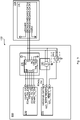
- Fig. 2 and Fig. 3 illustrate a system 100 comprising a controller 200 and a user connector 300.
- the user connector 300 has two output ports.
- the controller 200 is configured for reading of both an RS485 data signal and a Wiegand data signal from such a user connector 300.
- a first logic circuit 240 is connected between the two input ports A, B at the RS485 transceiver 230 and the data ready port WG_ DATA_READY at the Wiegand interface 220.
- the output from the first logic circuit 240 determines whether the signal, denoted RS485 data signal, from the output port RO of the RS485 transceiver 230 is to be read at the Wiegand data port WIEGAND DATA as a Wiegand data signal or not.
- the controller 200 comprises an RS485 transceiver 230.
- the RS485 transceiver 230 has two input ports A, B. Each of the two input ports A, B is connected to a respective one of the two output ports of the user connector 300 for reading one data signal on each of the output ports from the user connector 300 (in Fig. 3 denoted "RS485A/WIEGAND DATA0" and "RS485B/WIEGAND DATA1", respectively).
- the RS485 transceiver 230 has an output port RO for providing an RS485 data signal that is defined by the data signals read on the two output ports.
- the controller 200 further comprises an RS485 interface 210.
- the RS485 interface 210 has an RS485 data port RS485_RX.
- the RS485 data port RS485_RX is connected to the output port RO of the RS485 transceiver 230 for receiving the RS485 data signal.
- the controller 200 further comprises a Wiegand interface 220.
- the Wiegand interface 220 has a Wiegand data port WIEGAND DATA connected to the output port RO of the RS485 transceiver 230 for receiving the RS485 data signal.
- the Wiegand interface 220 has a data ready port WG_ DATA_READY connected to the two input ports A, B via a first logic circuit 240 for determining whether the RS485 data signal is to be read as a Wiegand data signal or not on the Wiegand data port WIEGAND DATA.
- controller 200 Further details of the controller 200 will now be disclosed.
- the signal output at the two output ports of the user connector 300 could be either a Wiegand data signal or an RS485 data signal.
- the controller 200 is transparent to this and thus enables the signal to be read as an RS485 data signal at the RS485 interface 210 and a Wiegand data signal at the Wiegand interface 220 regardless if the signal output at the two output ports of the user connector 300 is a Wiegand data signal or an RS485 data signal.
- Wiegand data signals are signalled using pseudo-differential signalling and RS485 data signals are signalled using differential signalling.
- the output of the RS485 transceiver 230 i.e., the RS485 data signal provided at the output port RO of the RS485 transceiver 230 will thus correctly represent the data of a Wiegand data signal.
- both data lines take a high value. This is an undefined state in the RS485 specification. This implies that the RS485 transceiver 230 will not be able to interpret the signal from the user connector 300 if the signals read at both the two input ports A, B are high. This implies that the Wiegand interface 220 cannot decide whether data is to be read on the Wiegand data port WIEGAND DATA or not. This issue is solved by means of using the first logic circuit 240 as disclosed above.
- the RS485 data signal is not to be read as a Wiegand data signal on the Wiegand data port WIEGAND DATA when the idle state of the values at the two output ports of the user connector 300 is detected by the first logic circuit 240.
- the RS485 data signal is to be read as a Wiegand data signal on the Wiegand data port WIEGAND DATA when the idle state of the values at the two output ports of the user connector 300 is not detected by the first logic circuit 240.
- the idle state of the user connector 300 is detected by the first logic circuit 240 when the values at both the two output ports of the user connector 300 are high. Further, the idle state of the values at the two output ports of the user connector 300 is then not detected by the first logic circuit 240 when the value at one or both of the two output ports of the user connector 300 is low. This implies that the first logic circuit 240 exhibits the functionality of a logic AND gate.
- the first logic circuit 240 is a logic AND circuit.
- the logic AND circuit could be implemented either by a single logic AND gate, or two logic NAND gates, or three logic NOR gates.
- the data ready port WG_ DATA_READY is active low. This implies that the Wiegand interface 220 is configured to be ready to read data (i.e., the RS485 data signal) as a Wiegand data signal on the Wiegand data port WIEGAND DATA when the input to the data ready port WG_ DATA_READY is low, such as binary value 0.
- the RS485 data signal is to be read as a Wiegand data signal on the Wiegand data port WIEGAND DATA only when the output from logic AND circuit is low.
- the Wiegand interface 220 is to not read data (i.e., the RS485 data signal) as a Wiegand data signal on the Wiegand data port WIEGAND DATA when a faulty state is detected.
- the controller 200 is thus configured to distinguish between whether the RS485 data signal is in a faulty state or not.
- the Wiegand interface 220 has a fault indicator port WG_ FAULT IO connected to the two input ports A, B via a second logic circuit 250 for determining whether the RS485 data signal is in a faulty state or not.
- the second logic circuit 250 is a logic OR circuit.
- the logic OR circuit could be implemented either by a single logic OR gate, or three logic NAND gates, or two logic NOR gates.
- the fault indicator port WG_ FAULT IO is active low. This implies that the Wiegand interface 220 is configured to not be ready to read data (i.e., the RS485 data signal) as a Wiegand data signal on the Wiegand data port WIEGAND DATA when the input to the fault indicator port WG_ FAULT IO is low, such as binary value 0.
- the Wiegand interface 220 is configured to not be ready to read data (i.e., the RS485 data signal) as a Wiegand data signal on the Wiegand data port WIEGAND DATA when the input to the fault indicator port WG_ FAULT IO is low, such as binary value 0.
- the RS485 data signal is in a faulty state, and not to be read as the Wiegand data signal on the Wiegand data port WIEGAND DATA, when the output from the logic OR circuit is low.
- the system 100 comprises both the controller 200 and the user connector 300. There could be different types of such systems 100.
- the controller 200 comprises, is collocated with, or integrated with, an electronic access control unit and the user connector 300 comprises, is collocated with, or integrated with, an electronic card reader for reading information from an electronic access card of a user.
- the data signal read on each of the output ports from the user connector 300 could represent a signal from the electronic card reader.
- the signal from the electronic card reader represents information, typically a numeric code or other types of credentials, read by the electronic card reader from the electronic access card.
- This signal is then, according to the herein disclosed controller 200, passed on to the RS485 interface 210 and the Wiegand interface 220 as an RS485 data signal (to be read as a Wiegand data signal at the Wiegand data port WIEGAND DATA of the Wiegand interface 220).
- the information read from the electronic access card could then be passed on to the electronic access control unit either from the RS485 interface 210 or the Wiegand interface 220, depending on the implementation of the electronic access control unit.
- the electronic access control unit could then grant or refuse access to the user based on the credential presented, optionally in combination with a personal identification number (PIN) as provided as input to the electronic access control unit by the user.
- PIN personal identification number
- the controller 200 comprises, is collocated with, or integrated with, a point of sale (POS) terminal (either provide as a stand-alone device or part of another device or system, such as an electronic ticketing system) and the user connector 300 comprises, is collocated with, or integrated with, an electronic card reader for reading information from a credit card or a debit card, in the form of a smart card, from a user.
- POS point of sale
- the data signal read on each of the output ports from the user connector 300 could represent a signal from the electronic card reader.
- the signal from the electronic card reader represents information, typically a numeric code or other types of credentials, read by the electronic card reader from the credit card or debit card.
- This signal is then, according to the herein disclosed controller 200, passed on to the RS485 interface 210 and the Wiegand interface 220 as an RS485 data signal (to be read as a Wiegand data signal at the Wiegand data port WIEGAND DATA of the Wiegand interface 220).
- the information read from the credit card or debit card could then be passed on to the POS terminal either from the RS485 interface 210 or the Wiegand interface 220, depending on the implementation of the POS unit.
- the POS unit could the grant or refuse a financial transaction, such as payment for a service or a purchase, as requested by the user based on the credential presented, possibly in combination with a PIN as provided as input to the POS unit by the user.
- the controller 200 comprises, is collocated with, or integrated with, an automated teller machine (ATM) terminal (also known as a cash machine terminal), and the user connector 300 comprises, is collocated with, or integrated with, an electronic card reader for reading information from a bank card, in the form of a smart card, from a user.
- ATM automated teller machine
- the data signal read on each of the output ports from the user connector 300 could represent a signal from the electronic card reader.
- the signal from the electronic card reader represents information, typically a numeric code or other types of credentials, read by the electronic card reader from the bank card.
- This signal is then, according to the herein disclosed controller 200, passed on to the RS485 interface 210 and the Wiegand interface 220 as an RS485 data signal (to be read as a Wiegand data signal at the Wiegand data port WIEGAND DATA of the Wiegand interface 220).
- the information read from the bank card could then be passed on to the ATM terminal either from the RS485 interface 210 or the Wiegand interface 220, depending on the implementation of the ATM terminal.
- the ATM terminal could then grant or refuse a service, such as a cash withdrawal, a cash deposit, a funds transfer, or an account information inquiry, or the like, as requested by the user based on the credential presented in combination with a PIN as provided as input to the ATM terminal by the user.
- Fig. 4 schematically illustrates a system 100 comprising a controller 200 having an electronic access control unit, where the controller 200 is connected to a single user connector 300 that comprises a single Wiegand installation of the card reader.
- Fig. 5 schematically illustrates a system 100 comprising a controller 200 having an electronic access control unit, where the controller 200 is connected to at least one user connector 300 where each user connector 300 comprises a single RS485 installations of the card reader, or where one single user connector 300 comprises at least one RS485 installations of the card reader.
- the electronic access control unit could be replaced by a POS terminal or an ATM terminal as disclosed above.
- Fig. 6 is a flowchart illustrating an embodiment of a method for reading of both an RS485 data signal and a Wiegand data signal from a user connector 300 having two output ports. The methods are performed by the controller 200. The methods are advantageously provided as computer programs 320.
- the controller 200 comprises an RS485 transceiver 230, an RS485 interface 210, and a Wiegand interface 220.
- S104 The RS485 data signal that is defined by the data signals read on the two output ports is provided at an output port RO of the RS485 transceiver 230.
- the RS485 data signal is received at an RS485 data port RS485_RX of the RS485 interface 210.
- the RS485 data port RS485_RX is connected to the output port RO of the RS485 transceiver 230.
- the RS485 data signal is received at a Wiegand data port WIEGAND DATA of the Wiegand interface 220.
- the Wiegand data port WIEGAND DATA is connected to the output port RO of the RS485 transceiver 230.
- S110 It is determined, at a data ready port WG_ DATA_READY of the Wiegand interface 220 whether the RS485 data signal is to be read as a Wiegand data signal or not on the Wiegand data port WIEGAND DATA.
- the data ready port WG_ DATA_READY is connected to the two input ports A, B via a first logic circuit 240.
- the data ready port WG_ DATA_READY could be active low.
- the first logic circuit 240 could be a logic AND circuit.
- the RS485 data signal could be read as the Wiegand data signal on the Wiegand data port WIEGAND DATA only when the output from the logic AND circuit is low.
- the method comprises determining whether the RS485 data signal is in a faulty state or not using a fault indicator port WG_ FAULT IO of the Wiegand interface 220, where the fault indicator port WG_ FAULT IO is connected to the two input ports A, B via a second logic circuit 250.
- the fault indicator port WG_ FAULT IO could be active low.
- the second logic circuit 250 could be a logic OR circuit.
- the method comprises identifying the RS485 data signal to be in a faulty state and not reading as the Wiegand data signal on the Wiegand data port WIEGAND DATA when the output from the logic OR circuit is low.
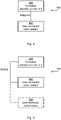
- Fig. 7 schematically illustrates, in terms of a number of functional units, the components of a controller 200 according to an embodiment.
- Processing circuitry 710 is provided using any combination of one or more of a suitable central processing unit (CPU), multiprocessor, microcontroller, digital signal processor (DSP), etc., capable of executing software instructions stored in a computer program product 810 (as in Fig. 8 ), e.g. in the form of a storage medium 730.
- the processing circuitry 710 may further be provided as at least one application specific integrated circuit (ASIC), or field programmable gate array (FPGA).
- ASIC application specific integrated circuit
- FPGA field programmable gate array
- the processing circuitry 710 is configured to cause the controller 200 to perform a set of operations, or steps, as disclosed above.
- the storage medium 730 may store the set of operations
- the processing circuitry 710 may be configured to retrieve the set of operations from the storage medium 730 to cause the controller 200 to perform the set of operations.
- the set of operations maybe provided as a set of executable instructions.
- the processing circuitry 710 is thereby arranged to execute methods as herein disclosed.
- the storage medium 730 may also comprise persistent storage, which, for example, can be any single one or combination of magnetic memory, optical memory, solid state memory or even remotely mounted memory.
- the controller 200 may further comprise a communications interface 720 at least configured for communications with other entities, functions, nodes, and devices, such as the user connector 300.
- the communications interface 720 may comprise one or more transmitters and receivers, comprising analogue and digital components.
- the communications interface 720 may comprise the RS485 interface 210 and the Wiegand interface 220.
- the communications interface 720 may further comprise the RS485 transceiver 230, the first logic circuit 240, and/or the second logic circuit 250.
- the processing circuitry 710 controls the general operation of the controller 200 e.g. by sending data and control signals to the communications interface 720 and the storage medium 730, by receiving data and reports from the communications interface 720, and by retrieving data and instructions from the storage medium 730.
- Other components, as well as the related functionality, of the controller 200 are omitted in order not to obscure the concepts presented herein.
- the controller 200 may be provided as a standalone device or as a part of at least one further device. Thus, a first portion of the instructions performed by the controller 200 may be executed in a first device, and a second portion of the of the instructions performed by the controller 200 may be executed in a second device; the herein disclosed embodiments are not limited to any particular number of devices on which the instructions performed by the controller 200 may be executed. Hence, the methods according to the herein disclosed embodiments are suitable to be performed by a controller 200 residing in a cloud computational environment. Therefore, although a single processing circuitry 710 is illustrated in Fig. 7 the processing circuitry 710 may be distributed among a plurality of devices, or nodes. The same applies to the computer program 820 of Fig. 8 .
- Fig. 8 shows one example of a computer program product 810 comprising computer readable storage medium 830.
- a computer program 820 can be stored, which computer program 820 can cause the processing circuitry 710 and thereto operatively coupled entities and devices, such as the communications interface 720 and the storage medium 730, to execute methods according to embodiments described herein.
- the computer program 820 and/or computer program product 810 may thus provide means for performing any steps as herein disclosed.
- the computer program product 810 is illustrated as an optical disc, such as a CD (compact disc) or a DVD (digital versatile disc) or a Blu-Ray disc.
- the computer program product 810 could also be embodied as a memory, such as a random access memory (RAM), a read-only memory (ROM), an erasable programmable read-only memory (EPROM), or an electrically erasable programmable read-only memory (EEPROM) and more particularly as a non-volatile storage medium of a device in an external memory such as a USB (Universal Serial Bus) memory or a Flash memory, such as a compact Flash memory.
- the computer program 820 is here schematically shown as a track on the depicted optical disk, the computer program 820 can be stored in any way which is suitable for the computer program product 810.
Landscapes
- Engineering & Computer Science (AREA)
- Theoretical Computer Science (AREA)
- General Engineering & Computer Science (AREA)
- Physics & Mathematics (AREA)
- General Physics & Mathematics (AREA)
- Computer Hardware Design (AREA)
- Computer Networks & Wireless Communication (AREA)
- Signal Processing (AREA)
- Communication Control (AREA)
Claims (15)
- Steuerung (200) zum Lesen sowohl eines RS485-Datensignals als auch eines Wiegand-Datensignals von einem Benutzerverbindungsstück (300), das zwei Ausgangsanschlüsse aufweist, wobei die Steuerung (200), Folgendes umfasst:einen RS485-Sendeempfänger (230) mit zwei Eingangsanschlüssen (A, B), von denen jeder mit einem entsprechenden der zwei Ausgangsanschlüsse des Benutzerverbindungsstücks (300) verbunden ist, um ein einzelnes Datensignal von jedem der Ausgangsanschlüsse des Benutzerverbindungsstücks (300) zu lesen, und mit einem Ausgangsanschluss (RO) zum Bereitstellen eines RS485-Datensignals, das durch die Datensignale definiert ist, die an den zwei Ausgangsanschlüssen gelesen werden,eine RS485-Schnittstelle (210) mit einem RS485-Datenanschluss (RS485_RX), der mit dem Ausgangsanschluss (RO) des RS485-Sendeempfängers (230) verbunden ist, um das RS485-Datensignal zu empfangen,eine Wiegand-Schnittstelle (220) mit einem Wiegand-Datenanschluss (WIEGAND DATA), der mit dem Ausgangsanschluss (RO) des RS485-Sendeempfängers (230) verbunden ist, um das RS485-Datensignal zu empfangen, und mit einem Daten-Bereit-Anschluss (WG_
DATA_READY ), der über eine erste Logikschaltung (240), die in der Steuerung (200) enthalten ist, mit den zwei Eingangsanschlüssen (A, B) verbunden ist, um zu bestimmen, ob das RS485-Datensignal an dem Wiegand-Datenanschluss (WIEGAND DATA) als ein Wiegand-Datensignal zu lesen ist oder nicht. - Steuerung (200) nach Anspruch 1, wobei der Daten-Bereit-Anschluss (WG_
DATA_READY ) low-aktiv ist. - Steuerung (200) nach Anspruch 1 oder 2, wobei die erste Logikschaltung (240) eine UND-Logikschaltung ist.
- Steuerung (200) nach einer Kombination aus Anspruch 2 und Anspruch 3, wobei das RS485-Datensignal nur dann als das Wiegand-Datensignal an dem Wiegand-Datenanschluss (WIEGAND DATA) zu lesen ist, wenn der Ausgang der UND-Logikschaltung low ist.
- Steuerung (200) nach einem der vorhergehenden Ansprüche, wobei die Wiegand-Schnittstelle (220) einen Fehlerindikatoranschluss (WG_
FAULT IO ) aufweist, der mit den zwei Eingangsanschlüssen (A, B) über eine zweite Logikschaltung (250) verbunden ist, um zu bestimmen, ob sich das RS485-Datensignal in einem Fehlerzustand befindet oder nicht. - Steuerung (200) nach Anspruch 5, wobei der Fehlerindikatoranschluss (WG_
FAULT IO ) low-aktiv ist. - Steuerung (200) nach Anspruch 5 oder Anspruch 6, wobei die zweite Logikschaltung eine ODER-Logikschaltung ist.
- Steuerung (200) nach einer Kombination aus Anspruch 6 und Anspruch 7, wobei sich das RS485-Datensignal in einem Fehlerzustand befindet und nicht als das Wiegand-Datensignal an dem Wiegand-Datenanschluss (WIEGAND DATA) zu lesen ist, wenn der Ausgang der ODER-Logikschaltung low ist.
- System, (100) die Steuerung (200) nach einem der vorhergehenden Ansprüche und das Benutzerverbindungsstück (300) umfassend.
- System (100) nach Anspruch 9, wobei die Steuerung (200) eine elektronische Zugangssteuereinheit ist.
- System (100) nach Anspruch 9 oder 10, wobei das Benutzerverbindungsstück (300) ein elektronisches Kartenlesegerät ist.
- System (100) nach Anspruch 12, wobei das Benutzerverbindungsstück (300) eine einzelne Wiegand-Installation des Kartenlesegeräts umfasst.
- System (100) nach Anspruch 12, wobei das Benutzerverbindungsstück (300) mindestens eine RS485-Installation des Kartenlesegeräts umfasst.
- Verfahren zum Lesen sowohl eines RS485-Datensignals als auch eines Wiegand-Datensignals von einem Benutzerverbindungsstück (300), das zwei Ausgangsanschlüsse aufweist, wobei das Verfahren von einer Steuerung (200) ausgeführt wird, die einen RS485-Sendeempfänger (230), eine RS485-Schnittstelle (210) und eine Wiegand-Schnittstelle (220) umfasst, wobei das Verfahren Folgendes umfasst:Lesen (S102) eines Datensignals an jedem der Ausgangsanschlüsse des Benutzerverbindungsstücks (300) an zwei Eingangsanschlüssen (A, B) des RS485-Sendeempfängers (230), wobei jeder der zwei Eingangsanschlüsse (A, B) mit einem entsprechenden der zwei Ausgangsanschlüsse des Benutzerverbindungsstücks (300) verbunden ist,Bereitstellen (S104) des RS485-Datensignals, das durch die Datensignale definiert ist, die an den zwei Ausgangsanschlüssen gelesen werden, an einem Ausgangsanschluss (RO) des RS485-Sendeempfängers (230),Empfangen (S106) des RS485-Datensignals an einem RS485-Datenanschluss (RS485_RX) der RS485-Schnittstelle (210), wobei der RS485-Datenanschluss (RS485_RX) mit dem Ausgangsanschluss (RO) des RS485-Sendeempfängers (230) verbunden ist,Empfangen (S108) des RS485-Datensignals an einem Wiegand-Datenanschluss (WIEGAND DATA) der Wiegand-Schnittstelle (220), wobei der Wiegand-Datenanschluss (WIEGAND DATA) mit dem Ausgangsanschluss (RO) des RS485-Sendeempfängers (230) verbunden ist, undBestimmen (S110), ob das RS485-Datensignal an dem Wiegand-Datenanschluss (WIEGAND DATA) als ein Wiegand-Datensignal zu lesen ist oder nicht, an einem Daten-Bereit-Anschluss (WG_
DATA_READY ) der Wiegand-Schnittstelle (220), wobei der Daten-Bereit-Anschluss (WG_DATA_READY ) über eine erste Logikschaltung (240), die in der Steuerung (200) enthalten ist, mit den zwei Eingangsanschlüssen (A, B) verbunden ist. - Computerprogramm (820) zum Empfangen von Signalen von dem Benutzerverbindungsstück (300), wobei das Computerprogramm (820) Computercode umfasst, der beim Abarbeiten in Verarbeitungsschaltkreisen (710) einer Steuerung (200), die einen RS485-Sendeempfänger (230), eine RS485-Schnittstelle (210) und eine Wiegand-Schnittstelle (220) umfasst, die Steuerung zu Folgendem veranlasst:Lesen (S102) eines einzelnen Datensignals an jedem der Ausgangsanschlüsse des Benutzerverbindungsstücks (300) an zwei Eingangsanschlüssen (A, B) des RS485-Sendeempfängers (230), wobei jeder der zwei Eingangsanschlüsse (A, B) mit einem entsprechenden der zwei Ausgangsanschlüsse des Benutzerverbindungsstücks (300) verbunden ist,Bereitstellen (S104) des RS485-Datensignals, das durch die Datensignale definiert ist, die an den zwei Ausgangsanschlüssen gelesen werden, an einem Ausgangsanschluss (RO) des RS485-Sendeempfängers (230),Empfangen (S106) des RS485-Datensignals an einem RS485-Datenanschluss (RS485_RX) der RS485-Schnittstelle (210), wobei der RS485-Datenanschluss (RS485_RX) mit dem Ausgangsanschluss (RO) des RS485-Sendeempfängers (230) verbunden ist,Empfangen (S108) des RS485-Datensignals an einem Wiegand-Datenanschluss (WIEGAND DATA) der Wiegand-Schnittstelle (220), wobei der Wiegand-Datenanschluss (WIEGAND DATA) mit dem Ausgangsanschluss (RO) des RS485-Sendeempfängers (230) verbunden ist, undBestimmen (S110), ob das RS485-Datensignal an dem Wiegand-Datenanschluss (WIEGAND DATA) als ein Wiegand-Datensignal zu lesen ist oder nicht, an einem Daten-Bereit-Anschluss (WG_
DATA_READY ) der Wiegand-Schnittstelle (220), wobei der Daten-Bereit-Anschluss (WG_DATA_READY ) über eine erste Logikschaltung (240), die in der Steuerung (200) enthalten ist, mit den zwei Eingangsanschlüssen (A, B) verbunden ist.
Priority Applications (3)
| Application Number | Priority Date | Filing Date | Title |
|---|---|---|---|
| EP21163343.3A EP4060509B1 (de) | 2021-03-18 | 2021-03-18 | Steuergerät, verfahren und computerprogramm zum lesen eines rs485-datensignals und eines wiegand-datensignals |
| US17/570,450 US11875671B2 (en) | 2021-03-18 | 2022-01-07 | Controller, method, and computer program for reading of an RS485 data signal and a Wiegand data signal |
| CN202210223368.9A CN115114216B (zh) | 2021-03-18 | 2022-03-09 | 读取rs485数据信号和韦根数据信号的控制器、方法和介质 |
Applications Claiming Priority (1)
| Application Number | Priority Date | Filing Date | Title |
|---|---|---|---|
| EP21163343.3A EP4060509B1 (de) | 2021-03-18 | 2021-03-18 | Steuergerät, verfahren und computerprogramm zum lesen eines rs485-datensignals und eines wiegand-datensignals |
Publications (2)
| Publication Number | Publication Date |
|---|---|
| EP4060509A1 EP4060509A1 (de) | 2022-09-21 |
| EP4060509B1 true EP4060509B1 (de) | 2023-01-04 |
Family
ID=75108154
Family Applications (1)
| Application Number | Title | Priority Date | Filing Date |
|---|---|---|---|
| EP21163343.3A Active EP4060509B1 (de) | 2021-03-18 | 2021-03-18 | Steuergerät, verfahren und computerprogramm zum lesen eines rs485-datensignals und eines wiegand-datensignals |
Country Status (3)
| Country | Link |
|---|---|
| US (1) | US11875671B2 (de) |
| EP (1) | EP4060509B1 (de) |
| CN (1) | CN115114216B (de) |
Families Citing this family (1)
| Publication number | Priority date | Publication date | Assignee | Title |
|---|---|---|---|---|
| WO2026082286A1 (en) * | 2024-10-17 | 2026-04-23 | Assa Abloy Ab | Wiegand using single 485 transceiver |
Family Cites Families (14)
| Publication number | Priority date | Publication date | Assignee | Title |
|---|---|---|---|---|
| WO2010130857A1 (es) | 2009-05-12 | 2010-11-18 | Carlos Fontes Vila | Sistema de control de accesos y presencia por lectura biometrica de partes de la mano con control por bluetooth |
| US20140002236A1 (en) * | 2010-12-02 | 2014-01-02 | Viscount Security Systems Inc. | Door Lock, System and Method for Remotely Controlled Access |
| CN103942510A (zh) * | 2013-01-21 | 2014-07-23 | 上海洪剑智能科技有限公司 | 一种韦根信号读取及转换装置 |
| WO2016019474A1 (en) * | 2014-08-07 | 2016-02-11 | 8857911 Canada Inc. | Proximity access control devices, systems and related methods |
| US10635629B2 (en) * | 2015-12-09 | 2020-04-28 | Lockheed Martin Corporation | Inter-integrated circuit (I2C) bus extender |
| EP3507672B1 (de) * | 2016-09-05 | 2024-07-03 | IOT.nxt BV | Schnittstellensystem und -verfahren für softwaredefinierte vorrichtung |
| US10452877B2 (en) | 2016-12-16 | 2019-10-22 | Assa Abloy Ab | Methods to combine and auto-configure wiegand and RS485 |
| CN206931080U (zh) * | 2017-06-21 | 2018-01-26 | 克立司帝控制系统(上海)有限公司 | 基于can总线连接的多门门禁系统 |
| CN207166528U (zh) * | 2017-08-25 | 2018-03-30 | 重庆步航科技有限公司 | 韦根协议转换控制装置 |
| US10789797B2 (en) * | 2017-09-22 | 2020-09-29 | Schlage Lock Company Llc | Peripheral controller in an access control system |
| US10783338B2 (en) * | 2018-03-08 | 2020-09-22 | Amazon Technologies, Inc. | Integrated access control system |
| CN109325477A (zh) * | 2018-11-20 | 2019-02-12 | 深圳市中阳通讯有限公司 | 一种近红外人脸识别模块 |
| US10797893B2 (en) * | 2018-12-13 | 2020-10-06 | Cisco Technology, Inc. | Single pair ethernet management interface |
| CN114839897A (zh) * | 2021-02-02 | 2022-08-02 | 同方锐安科技有限公司 | 一种多接口、输入输出可配置韦根通信扩展板 |
-
2021
- 2021-03-18 EP EP21163343.3A patent/EP4060509B1/de active Active
-
2022
- 2022-01-07 US US17/570,450 patent/US11875671B2/en active Active
- 2022-03-09 CN CN202210223368.9A patent/CN115114216B/zh active Active
Also Published As
| Publication number | Publication date |
|---|---|
| CN115114216A (zh) | 2022-09-27 |
| US20220301418A1 (en) | 2022-09-22 |
| CN115114216B (zh) | 2024-11-01 |
| EP4060509A1 (de) | 2022-09-21 |
| US11875671B2 (en) | 2024-01-16 |
Similar Documents
| Publication | Publication Date | Title |
|---|---|---|
| US11995634B2 (en) | Systems and methods for providing near field communications | |
| EP3001323B1 (de) | Serielle Peripherieschnittstelle | |
| US10162723B2 (en) | Electronic card and detecting method thereof | |
| US20190012005A1 (en) | Method and device for asynchronous touch and asynchronous display on dual-screen and computer readable storage medium | |
| CN103793307A (zh) | 电子装置及其管理方法与机柜伺服系统 | |
| US20070067541A1 (en) | Method and apparatus for automatically adjusting bus widths | |
| EP2704021B1 (de) | SRAM-Handshake | |
| JP2026048755A (ja) | 取引カードによる取引の試行のためのデータを保存し処理する技術 | |
| EP4060509B1 (de) | Steuergerät, verfahren und computerprogramm zum lesen eines rs485-datensignals und eines wiegand-datensignals | |
| CN103679250A (zh) | 有线标签的接口仲裁 | |
| US9158609B2 (en) | Universal serial bus testing device | |
| US9055432B2 (en) | Targeted muting for communication between electronic appliances | |
| CN104346881B (zh) | 数据传输装置及利用该装置的金融设备 | |
| US9798904B2 (en) | IC card reader and operating method thereof | |
| US9088304B2 (en) | Interface deactivation for communication between electronic appliances | |
| US20080013396A1 (en) | Memory card having multiple interfaces and reset control method thereof | |
| US10970693B2 (en) | Semi-automatic configuration of a self-service terminal | |
| CN105320215A (zh) | 一种集成刷卡功能的分体或一体化主机架构 | |
| US20060027654A1 (en) | Card reader and data transmission method therefor | |
| US20240311324A1 (en) | Fabric connection assist transceiver device identification system | |
| US9367506B2 (en) | Executive device and control method and electronic system thereof | |
| KR101499334B1 (ko) | 인터럽 명령 감지 장치 및 방법 | |
| US7975087B2 (en) | Control and communication unit between a terminal and a microcircuit card | |
| KR20080037127A (ko) | 복수 밴사 접속기능을 갖는 신용카드 조회기 | |
| KR101726519B1 (ko) | 금융기기의 모듈 장착 감지 장치 |
Legal Events
| Date | Code | Title | Description |
|---|---|---|---|
| PUAI | Public reference made under article 153(3) epc to a published international application that has entered the european phase |
Free format text: ORIGINAL CODE: 0009012 |
|
| STAA | Information on the status of an ep patent application or granted ep patent |
Free format text: STATUS: REQUEST FOR EXAMINATION WAS MADE |
|
| 17P | Request for examination filed |
Effective date: 20211012 |
|
| AK | Designated contracting states |
Kind code of ref document: A1 Designated state(s): AL AT BE BG CH CY CZ DE DK EE ES FI FR GB GR HR HU IE IS IT LI LT LU LV MC MK MT NL NO PL PT RO RS SE SI SK SM TR |
|
| GRAP | Despatch of communication of intention to grant a patent |
Free format text: ORIGINAL CODE: EPIDOSNIGR1 |
|
| STAA | Information on the status of an ep patent application or granted ep patent |
Free format text: STATUS: GRANT OF PATENT IS INTENDED |
|
| RIC1 | Information provided on ipc code assigned before grant |
Ipc: H04L 69/18 20220101ALI20220920BHEP Ipc: G06F 13/10 20060101ALI20220920BHEP Ipc: G06F 13/40 20060101ALI20220920BHEP Ipc: G06F 13/42 20060101ALI20220920BHEP Ipc: H04L 12/40 20060101ALI20220920BHEP Ipc: G06F 13/38 20060101AFI20220920BHEP |
|
| INTG | Intention to grant announced |
Effective date: 20221019 |
|
| GRAS | Grant fee paid |
Free format text: ORIGINAL CODE: EPIDOSNIGR3 |
|
| GRAA | (expected) grant |
Free format text: ORIGINAL CODE: 0009210 |
|
| STAA | Information on the status of an ep patent application or granted ep patent |
Free format text: STATUS: THE PATENT HAS BEEN GRANTED |
|
| AK | Designated contracting states |
Kind code of ref document: B1 Designated state(s): AL AT BE BG CH CY CZ DE DK EE ES FI FR GB GR HR HU IE IS IT LI LT LU LV MC MK MT NL NO PL PT RO RS SE SI SK SM TR |
|
| REG | Reference to a national code |
Ref country code: GB Ref legal event code: FG4D |
|
| REG | Reference to a national code |
Ref country code: SE Ref legal event code: TRGR |
|
| REG | Reference to a national code |
Ref country code: DE Ref legal event code: R096 Ref document number: 602021001126 Country of ref document: DE |
|
| REG | Reference to a national code |
Ref country code: CH Ref legal event code: EP |
|
| REG | Reference to a national code |
Ref country code: AT Ref legal event code: REF Ref document number: 1542467 Country of ref document: AT Kind code of ref document: T Effective date: 20230115 |
|
| REG | Reference to a national code |
Ref country code: IE Ref legal event code: FG4D |
|
| REG | Reference to a national code |
Ref country code: LT Ref legal event code: MG9D |
|
| REG | Reference to a national code |
Ref country code: NL Ref legal event code: MP Effective date: 20230104 |
|
| P01 | Opt-out of the competence of the unified patent court (upc) registered |
Effective date: 20230505 |
|
| REG | Reference to a national code |
Ref country code: AT Ref legal event code: MK05 Ref document number: 1542467 Country of ref document: AT Kind code of ref document: T Effective date: 20230104 |
|
| PG25 | Lapsed in a contracting state [announced via postgrant information from national office to epo] |
Ref country code: NL Free format text: LAPSE BECAUSE OF FAILURE TO SUBMIT A TRANSLATION OF THE DESCRIPTION OR TO PAY THE FEE WITHIN THE PRESCRIBED TIME-LIMIT Effective date: 20230104 |
|
| PG25 | Lapsed in a contracting state [announced via postgrant information from national office to epo] |
Ref country code: RS Free format text: LAPSE BECAUSE OF FAILURE TO SUBMIT A TRANSLATION OF THE DESCRIPTION OR TO PAY THE FEE WITHIN THE PRESCRIBED TIME-LIMIT Effective date: 20230104 Ref country code: PT Free format text: LAPSE BECAUSE OF FAILURE TO SUBMIT A TRANSLATION OF THE DESCRIPTION OR TO PAY THE FEE WITHIN THE PRESCRIBED TIME-LIMIT Effective date: 20230504 Ref country code: NO Free format text: LAPSE BECAUSE OF FAILURE TO SUBMIT A TRANSLATION OF THE DESCRIPTION OR TO PAY THE FEE WITHIN THE PRESCRIBED TIME-LIMIT Effective date: 20230404 Ref country code: LV Free format text: LAPSE BECAUSE OF FAILURE TO SUBMIT A TRANSLATION OF THE DESCRIPTION OR TO PAY THE FEE WITHIN THE PRESCRIBED TIME-LIMIT Effective date: 20230104 Ref country code: LT Free format text: LAPSE BECAUSE OF FAILURE TO SUBMIT A TRANSLATION OF THE DESCRIPTION OR TO PAY THE FEE WITHIN THE PRESCRIBED TIME-LIMIT Effective date: 20230104 Ref country code: HR Free format text: LAPSE BECAUSE OF FAILURE TO SUBMIT A TRANSLATION OF THE DESCRIPTION OR TO PAY THE FEE WITHIN THE PRESCRIBED TIME-LIMIT Effective date: 20230104 Ref country code: ES Free format text: LAPSE BECAUSE OF FAILURE TO SUBMIT A TRANSLATION OF THE DESCRIPTION OR TO PAY THE FEE WITHIN THE PRESCRIBED TIME-LIMIT Effective date: 20230104 Ref country code: AT Free format text: LAPSE BECAUSE OF FAILURE TO SUBMIT A TRANSLATION OF THE DESCRIPTION OR TO PAY THE FEE WITHIN THE PRESCRIBED TIME-LIMIT Effective date: 20230104 |
|
| PG25 | Lapsed in a contracting state [announced via postgrant information from national office to epo] |
Ref country code: PL Free format text: LAPSE BECAUSE OF FAILURE TO SUBMIT A TRANSLATION OF THE DESCRIPTION OR TO PAY THE FEE WITHIN THE PRESCRIBED TIME-LIMIT Effective date: 20230104 Ref country code: IS Free format text: LAPSE BECAUSE OF FAILURE TO SUBMIT A TRANSLATION OF THE DESCRIPTION OR TO PAY THE FEE WITHIN THE PRESCRIBED TIME-LIMIT Effective date: 20230504 Ref country code: GR Free format text: LAPSE BECAUSE OF FAILURE TO SUBMIT A TRANSLATION OF THE DESCRIPTION OR TO PAY THE FEE WITHIN THE PRESCRIBED TIME-LIMIT Effective date: 20230405 Ref country code: FI Free format text: LAPSE BECAUSE OF FAILURE TO SUBMIT A TRANSLATION OF THE DESCRIPTION OR TO PAY THE FEE WITHIN THE PRESCRIBED TIME-LIMIT Effective date: 20230104 |
|
| REG | Reference to a national code |
Ref country code: DE Ref legal event code: R097 Ref document number: 602021001126 Country of ref document: DE |
|
| PG25 | Lapsed in a contracting state [announced via postgrant information from national office to epo] |
Ref country code: SM Free format text: LAPSE BECAUSE OF FAILURE TO SUBMIT A TRANSLATION OF THE DESCRIPTION OR TO PAY THE FEE WITHIN THE PRESCRIBED TIME-LIMIT Effective date: 20230104 Ref country code: RO Free format text: LAPSE BECAUSE OF FAILURE TO SUBMIT A TRANSLATION OF THE DESCRIPTION OR TO PAY THE FEE WITHIN THE PRESCRIBED TIME-LIMIT Effective date: 20230104 Ref country code: MC Free format text: LAPSE BECAUSE OF FAILURE TO SUBMIT A TRANSLATION OF THE DESCRIPTION OR TO PAY THE FEE WITHIN THE PRESCRIBED TIME-LIMIT Effective date: 20230104 Ref country code: EE Free format text: LAPSE BECAUSE OF FAILURE TO SUBMIT A TRANSLATION OF THE DESCRIPTION OR TO PAY THE FEE WITHIN THE PRESCRIBED TIME-LIMIT Effective date: 20230104 Ref country code: DK Free format text: LAPSE BECAUSE OF FAILURE TO SUBMIT A TRANSLATION OF THE DESCRIPTION OR TO PAY THE FEE WITHIN THE PRESCRIBED TIME-LIMIT Effective date: 20230104 Ref country code: CZ Free format text: LAPSE BECAUSE OF FAILURE TO SUBMIT A TRANSLATION OF THE DESCRIPTION OR TO PAY THE FEE WITHIN THE PRESCRIBED TIME-LIMIT Effective date: 20230104 |
|
| PLBE | No opposition filed within time limit |
Free format text: ORIGINAL CODE: 0009261 |
|
| STAA | Information on the status of an ep patent application or granted ep patent |
Free format text: STATUS: NO OPPOSITION FILED WITHIN TIME LIMIT |
|
| PG25 | Lapsed in a contracting state [announced via postgrant information from national office to epo] |
Ref country code: SK Free format text: LAPSE BECAUSE OF FAILURE TO SUBMIT A TRANSLATION OF THE DESCRIPTION OR TO PAY THE FEE WITHIN THE PRESCRIBED TIME-LIMIT Effective date: 20230104 |
|
| REG | Reference to a national code |
Ref country code: BE Ref legal event code: MM Effective date: 20230331 |
|
| 26N | No opposition filed |
Effective date: 20231005 |
|
| PG25 | Lapsed in a contracting state [announced via postgrant information from national office to epo] |
Ref country code: LU Free format text: LAPSE BECAUSE OF NON-PAYMENT OF DUE FEES Effective date: 20230318 |
|
| REG | Reference to a national code |
Ref country code: IE Ref legal event code: MM4A |
|
| PG25 | Lapsed in a contracting state [announced via postgrant information from national office to epo] |
Ref country code: SI Free format text: LAPSE BECAUSE OF FAILURE TO SUBMIT A TRANSLATION OF THE DESCRIPTION OR TO PAY THE FEE WITHIN THE PRESCRIBED TIME-LIMIT Effective date: 20230104 Ref country code: IE Free format text: LAPSE BECAUSE OF NON-PAYMENT OF DUE FEES Effective date: 20230318 |
|
| PG25 | Lapsed in a contracting state [announced via postgrant information from national office to epo] |
Ref country code: BE Free format text: LAPSE BECAUSE OF NON-PAYMENT OF DUE FEES Effective date: 20230331 |
|
| PG25 | Lapsed in a contracting state [announced via postgrant information from national office to epo] |
Ref country code: IT Free format text: LAPSE BECAUSE OF FAILURE TO SUBMIT A TRANSLATION OF THE DESCRIPTION OR TO PAY THE FEE WITHIN THE PRESCRIBED TIME-LIMIT Effective date: 20230104 |
|
| REG | Reference to a national code |
Ref country code: CH Ref legal event code: PL |
|
| PG25 | Lapsed in a contracting state [announced via postgrant information from national office to epo] |
Ref country code: BG Free format text: LAPSE BECAUSE OF FAILURE TO SUBMIT A TRANSLATION OF THE DESCRIPTION OR TO PAY THE FEE WITHIN THE PRESCRIBED TIME-LIMIT Effective date: 20230104 |
|
| PG25 | Lapsed in a contracting state [announced via postgrant information from national office to epo] |
Ref country code: BG Free format text: LAPSE BECAUSE OF FAILURE TO SUBMIT A TRANSLATION OF THE DESCRIPTION OR TO PAY THE FEE WITHIN THE PRESCRIBED TIME-LIMIT Effective date: 20230104 |
|
| PG25 | Lapsed in a contracting state [announced via postgrant information from national office to epo] |
Ref country code: CH Free format text: LAPSE BECAUSE OF NON-PAYMENT OF DUE FEES Effective date: 20240331 |
|
| PG25 | Lapsed in a contracting state [announced via postgrant information from national office to epo] |
Ref country code: CY Free format text: LAPSE BECAUSE OF FAILURE TO SUBMIT A TRANSLATION OF THE DESCRIPTION OR TO PAY THE FEE WITHIN THE PRESCRIBED TIME-LIMIT; INVALID AB INITIO Effective date: 20210318 |
|
| PG25 | Lapsed in a contracting state [announced via postgrant information from national office to epo] |
Ref country code: HU Free format text: LAPSE BECAUSE OF FAILURE TO SUBMIT A TRANSLATION OF THE DESCRIPTION OR TO PAY THE FEE WITHIN THE PRESCRIBED TIME-LIMIT; INVALID AB INITIO Effective date: 20210318 |
|
| PG25 | Lapsed in a contracting state [announced via postgrant information from national office to epo] |
Ref country code: TR Free format text: LAPSE BECAUSE OF FAILURE TO SUBMIT A TRANSLATION OF THE DESCRIPTION OR TO PAY THE FEE WITHIN THE PRESCRIBED TIME-LIMIT Effective date: 20230104 |
|
| PGFP | Annual fee paid to national office [announced via postgrant information from national office to epo] |
Ref country code: SE Payment date: 20260219 Year of fee payment: 6 |
|
| PGFP | Annual fee paid to national office [announced via postgrant information from national office to epo] |
Ref country code: GB Payment date: 20260219 Year of fee payment: 6 |
|
| PGFP | Annual fee paid to national office [announced via postgrant information from national office to epo] |
Ref country code: DE Payment date: 20260219 Year of fee payment: 6 |
|
| PGFP | Annual fee paid to national office [announced via postgrant information from national office to epo] |
Ref country code: FR Payment date: 20260220 Year of fee payment: 6 |