EP4060671A1 - Dispositif de positionnement - Google Patents
Dispositif de positionnement Download PDFInfo
- Publication number
- EP4060671A1 EP4060671A1 EP20887791.0A EP20887791A EP4060671A1 EP 4060671 A1 EP4060671 A1 EP 4060671A1 EP 20887791 A EP20887791 A EP 20887791A EP 4060671 A1 EP4060671 A1 EP 4060671A1
- Authority
- EP
- European Patent Office
- Prior art keywords
- positioning apparatus
- region
- upper unit
- unit
- movement
- Prior art date
- Legal status (The legal status is an assumption and is not a legal conclusion. Google has not performed a legal analysis and makes no representation as to the accuracy of the status listed.)
- Granted
Links
Images


Classifications
-
- G—PHYSICS
- G12—INSTRUMENT DETAILS
- G12B—CONSTRUCTIONAL DETAILS OF INSTRUMENTS, OR COMPARABLE DETAILS OF OTHER APPARATUS, NOT OTHERWISE PROVIDED FOR
- G12B5/00—Adjusting position or attitude, e.g. level, of instruments or other apparatus, or of parts thereof; Compensating for the effects of tilting or acceleration, e.g. for optical apparatus
-
- F—MECHANICAL ENGINEERING; LIGHTING; HEATING; WEAPONS; BLASTING
- F16—ENGINEERING ELEMENTS AND UNITS; GENERAL MEASURES FOR PRODUCING AND MAINTAINING EFFECTIVE FUNCTIONING OF MACHINES OR INSTALLATIONS; THERMAL INSULATION IN GENERAL
- F16M—FRAMES, CASINGS OR BEDS OF ENGINES, MACHINES OR APPARATUS, NOT SPECIFIC TO ENGINES, MACHINES OR APPARATUS PROVIDED FOR ELSEWHERE; STANDS; SUPPORTS
- F16M11/00—Stands or trestles as supports for apparatus or articles placed thereon ; Stands for scientific apparatus such as gravitational force meters
- F16M11/20—Undercarriages with or without wheels
- F16M11/2007—Undercarriages with or without wheels comprising means allowing pivoting adjustment
- F16M11/2021—Undercarriages with or without wheels comprising means allowing pivoting adjustment around a horizontal axis
-
- F—MECHANICAL ENGINEERING; LIGHTING; HEATING; WEAPONS; BLASTING
- F16—ENGINEERING ELEMENTS AND UNITS; GENERAL MEASURES FOR PRODUCING AND MAINTAINING EFFECTIVE FUNCTIONING OF MACHINES OR INSTALLATIONS; THERMAL INSULATION IN GENERAL
- F16M—FRAMES, CASINGS OR BEDS OF ENGINES, MACHINES OR APPARATUS, NOT SPECIFIC TO ENGINES, MACHINES OR APPARATUS PROVIDED FOR ELSEWHERE; STANDS; SUPPORTS
- F16M11/00—Stands or trestles as supports for apparatus or articles placed thereon ; Stands for scientific apparatus such as gravitational force meters
- F16M11/20—Undercarriages with or without wheels
- F16M11/22—Undercarriages with or without wheels with approximately constant height, e.g. with constant length of column or of legs
-
- F—MECHANICAL ENGINEERING; LIGHTING; HEATING; WEAPONS; BLASTING
- F16—ENGINEERING ELEMENTS AND UNITS; GENERAL MEASURES FOR PRODUCING AND MAINTAINING EFFECTIVE FUNCTIONING OF MACHINES OR INSTALLATIONS; THERMAL INSULATION IN GENERAL
- F16M—FRAMES, CASINGS OR BEDS OF ENGINES, MACHINES OR APPARATUS, NOT SPECIFIC TO ENGINES, MACHINES OR APPARATUS PROVIDED FOR ELSEWHERE; STANDS; SUPPORTS
- F16M7/00—Details of attaching or adjusting engine beds, frames, or supporting-legs on foundation or base; Attaching non-moving engine parts, e.g. cylinder blocks
-
- H—ELECTRICITY
- H01—ELECTRIC ELEMENTS
- H01F—MAGNETS; INDUCTANCES; TRANSFORMERS; SELECTION OF MATERIALS FOR THEIR MAGNETIC PROPERTIES
- H01F7/00—Magnets
- H01F7/02—Permanent magnets [PM]
- H01F7/0231—Magnetic circuits with PM for power or force generation
- H01F7/0252—PM holding devices
-
- H—ELECTRICITY
- H01—ELECTRIC ELEMENTS
- H01M—PROCESSES OR MEANS, e.g. BATTERIES, FOR THE DIRECT CONVERSION OF CHEMICAL ENERGY INTO ELECTRICAL ENERGY
- H01M10/00—Secondary cells; Manufacture thereof
- H01M10/04—Construction or manufacture in general
- H01M10/0404—Machines for assembling batteries
-
- H—ELECTRICITY
- H01—ELECTRIC ELEMENTS
- H01M—PROCESSES OR MEANS, e.g. BATTERIES, FOR THE DIRECT CONVERSION OF CHEMICAL ENERGY INTO ELECTRICAL ENERGY
- H01M10/00—Secondary cells; Manufacture thereof
- H01M10/42—Methods or arrangements for servicing or maintenance of secondary cells or secondary half-cells
- H01M10/48—Accumulators combined with arrangements for measuring, testing or indicating the condition of cells, e.g. the level or density of the electrolyte
-
- H—ELECTRICITY
- H01—ELECTRIC ELEMENTS
- H01M—PROCESSES OR MEANS, e.g. BATTERIES, FOR THE DIRECT CONVERSION OF CHEMICAL ENERGY INTO ELECTRICAL ENERGY
- H01M4/00—Electrodes
- H01M4/02—Electrodes composed of, or comprising, active material
- H01M4/13—Electrodes for accumulators with non-aqueous electrolyte, e.g. for lithium-accumulators; Processes of manufacture thereof
- H01M4/139—Processes of manufacture
Definitions
- the present disclosure relates to a positioning apparatus.
- a robot is structured such that end effector such as a hand is attached to the end of an arm and can grip a component or a work by means of the end effector.
- end effector such as a hand
- the operation of a robot is controlled according to position control.
- position control When the position of an object gripped is displaced from a preprogrammed target position, therefore, the robot might not be able to grip the object properly. It is therefore desired to finely adjust the position of an object so that the position of the object agrees with the target position.
- patent literature 1 discloses a work positioning apparatus capable of finely adjusting the horizontal position of a work.
- the above-mentioned related-art positioning apparatus is structured such that a table part not carrying a work is returned to the centering position by a volute spring. Therefore, the number of components in the related-art positioning apparatus is large, and the structure thereof is complicated. A larger number of components could lead to a larger size of the positioning apparatus. The manufacturing cost of the positioning apparatus is also increased accordingly. Further, an attempt to reduce the size of the positioning apparatus requires reducing the size of components and could lead to reduced durability of the components and, ultimately, reduced durability of the positioning apparatus.
- the positioning apparatus includes: an upper unit that includes a spherical body, a retainer part that retains the spherical body, and an upper plate part provided on the retainer part and adapted to carry a carried object; a lower unit that includes a lower plate part on which the upper unit is mounted and a guide part that marks a region of movement of the upper unit on the lower plate part; and a tilting structure that tilts the region of movement relative to a horizontal plane and guides the upper unit, on which the carried object is not mounted, toward a reference position located on a lower side of a tilt.
- the structure of a positioning apparatus is simplified.
- Fig. 1 is a perspective view of a carried object mounted on the positioning apparatus according to embodiment 1.
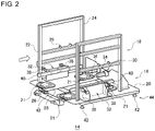
- Fig. 2 is a perspective view of a rack restriction apparatus provided with a positioning apparatus.
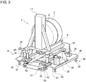
- Figs. 3 and 4 are perspective views showing how the carried object is mounted on the rack restriction apparatus. In Figs. 3 and 4 , illustration of a housing frame body 18 is omitted.
- the positioning apparatus 16 according to this embodiment is used to finely adjust the position of a carried object 1 mounted on a rack restriction apparatus 14.
- the carried object 1 includes, by way of one example, an electrode hoop 2 and an electrode rack 4 for supporting the electrode hoop 2.
- the electrode hoop 2 is produced by winding an electrode plate of a secondary battery around a bobbin, and has a through hole 6 in the center.
- the electrode rack 4 includes a rack body 8, a support shaft 10 projecting from the rack body 8 substantially in the horizontal direction, and a rack leg 12 projecting downward from the rack body 8.
- the electrode rack 4 according to this embodiment includes four rack legs 12.
- the electrode hoop 2 is supported by the electrode rack 4 such that the support shaft 10 is inserted in the through hole 6. In this embodiment, two electrode hoops 2 are supported by one electrode rack 4.
- the weight of the carried object 1 is, for example, 500 kg to 1000 kg.
- the carried object 1 is not limited to the electrode hoop 2 and the electrode rack 4.
- the rack restriction apparatus 14 includes the positioning apparatus 16 and the housing frame body 18.
- the positioning apparatus 16 includes a base plate 20 and a movable part 21.
- the carried object 1 is mounted on the base plate 20.
- the housing frame body 18 is fixed to the upper surface of the base plate 20.
- the housing frame body 18 surrounds the carried object 1 while the carried object 1 is placed on the base plate 20.
- the housing frame body 18 includes an entrance frame 22 and an exit frame 24 opposite to each other.
- the carried object 1 is inserted from the entrance frame 22 and mounted on the base plate 20.
- the end of the support shaft 10 faces the exit frame 24 while the carried object 1 is placed on the base plate 20.
- An arm (not shown) of a robot advances from the exit frame 24 to a position above the base plate 20, grips the electrode hoop 2 of the carried object 1, and dismantles the electrode hoop 2 from the support shaft 10.
- the housing frame body 18 includes a sensor 25 for sensing that the carried object 1 is mounted on the base plate 20.
- the movable part 21 is a floating unit that supports the carried object 1 and is fixed to the upper surface of the base plate 20.
- the movable part 21 includes an upper unit 26 and a lower unit 28.
- the positioning apparatus 16 of this embodiment includes four movable parts 21 to correspond to the four rack legs 12.
- the lower unit 28 of each movable part 21 is supported by the base plate 20.
- the upper unit 26 is mounted on the lower unit 28.
- the rack leg 12 of the electrode rack 4 is mounted on each upper unit 26. Displacement of each upper unit 26 relative to each lower unit 28 finely adjusts the position of the carried object 1.
- the positioning apparatus 16 includes a drawing mechanism 30 and a pair of lateral position adjustment mechanisms 32.
- the drawing mechanism 30 is provided on the side of the base plate 20 opposite to the entrance frame 22, i.e., toward the exit frame 24.
- the drawing mechanism 30 includes, by way of one example, an air cylinder 34 and a catching pawl 36 attached to the end of the piston provided in the air cylinder 34.
- the air cylinder 34 can extend or contract in the direction of advancement of the carried object 1, i.e., in the direction in which the entrance frame 22 and the exit frame 24 are aligned.
- the drawing mechanism 30 can finely adjust the position of the carried object 1 in the direction of advancement of the carried object 1 by catching the catching pawl 36 in the rack body 8 of the carried object 1 mounted on the upper unit 26 to extend or contract the air cylinder 34.
- the pair of lateral position adjustment mechanisms 32 are aligned in a direction (hereinafter, referred to as lateral direction for convenience) orthogonal to the direction of advancement of the carried object 1.
- Each lateral position adjustment mechanism 32 includes, by way of one example, a pair of air cylinders 38 and an extrusion rod 40 attached to the end of the piston provided in each air cylinder 38.
- the air cylinder 38 can extend or contract in the lateral direction.
- the pair of lateral position adjustment mechanisms 32 can finely adjust the position of the carried object 1 in the lateral direction by thrusting the respective extrusion rods 40 against the rack body 8 of the carried object 1 mounted on the upper unit 26 so as to extend or contract each air cylinder 38.
- the extrusion force of one of the lateral position mechanisms 32 is configured to be weaker than that of the other lateral position mechanism 32. This ensures that the lateral position of the carried object 1 is adjusted in a stable manner.
- the base plate 20 includes a leg part 42 that projects from the lower surface.
- the rack restriction apparatus 14 is supported on the floor face by the leg part 42.
- two leg parts 42 are provided at the edges of the base plate 20 toward the entrance frame 22 so as to be aligned in the lateral direction, and three leg parts 42 are provided at the edges toward the exit frame 24 so as to be aligned in the lateral direction.
- Each leg part 42 is formed by an adjuster bolt, etc. and can extend or contract independently. Therefore, leveling adjustment of the electrode rack 4 is possible by adjusting the length of each leg part 42.
- the positioning apparatus 16 has a tilting structure 44.
- the tilting structure 44 of this embodiment is formed by the leg part 42.
- the tilting structure 44 is a mechanism to tilt the movable part 21 relative to the horizontal plane.
- the movable part 21 and the tilting structure 44 will be described in detail.
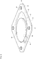
- Fig. 5 is a perspective view of the movable part 21 provided in the positioning apparatus 16.
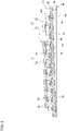
- Fig. 6 is a cross-sectional view of the positioning apparatus 16.
- the movable part 21 includes the upper unit 26 and the lower unit 28.
- the upper unit 26 includes a spherical body 46, a retainer part 48, and an upper plate part 50.
- the spherical body 46 is a high-rigidity ball formed by, for example, a steel ball.
- the upper unit 26 of this embodiment includes a plurality of spherical bodies 46.
- the plurality of spherical bodies 46 are arranged at predetermined intervals in a plan view.
- the retainer part 48 is a plate body extending in parallel to the base plate 20 and includes a plurality of through holes 52 connecting two opposite principal surfaces.
- the spherical body 46 is housed in each through hole 52. This ensures that the plurality of spherical bodies 46 are retained by the retainer part 48.
- the upper plate part 50 is provided on the retainer part 48.
- the upper plate part 50 is fixed to the upper surface of the retainer part 48.
- the carried object 1 is mounted on the upper surface of the upper plate part 50.
- the upper plate part 50 of this embodiment is structured such that a top plate 56 is mounted on a high-rigidity plate 54 formed by a hardened plate, etc. Further, the upper plate part 50 is circular in a plan view. The opening above each through hole 52 is blocked by the high-rigidity plate 54. Therefore, the spherical body 46 is in contact with the high-rigidity plate 54.
- the retainer part 48 and the upper plate part 50 may be formed by the same member and integrated with each other.
- the lower unit 28 includes a lower plate part 58 and a guide part 60.
- the lower plate part 58 is formed by, for example, a high-rigidity plate such as a hardened plate and is fixed to the upper surface of the base plate 20.
- the upper unit 26 is mounted on the lower plate part 58. In this state, the spherical body 46 is in contact with the upper surface of the lower plate part 58.
- the upper unit 26 can move on the upper surface of the lower unit 28 as the spherical body 46 rolls on the upper surface of the lower plate part 58.
- the central region on the upper surface of the lower plate part 58 forms a region of movement 62 of the upper unit 26.
- the upper unit 26 can move within the region of movement 62.
- the guide part 60 has a frame shape and marks the region of movement 62 by being fixed to the upper surface of the lower plate part 58.
- the guide part 60 extends on the peripheral part of the upper surface of the lower plate part 58 and surrounds the outer circumference of the region of movement 62.
- the region of movement 62 of this embodiment is circular in a plan view.
- the upper unit 26 is restricted from moving outside the region of movement 62 by butting against the guide part 60.
- the lower plate part 58 and the guide part 60 may be formed by the same member and integrated with each other.
- the tilting structure 44 tilts the region of movement 62 relative to the horizontal plane HP and guides the upper unit 26 on which the carried object 1 is not mounted toward the reference position located on the lower side of the tilt.
- Fig. 6 shows that the upper unit 26 is located at the reference position.
- the horizontal plane HP is the plane of installation of the positioning apparatus 16 or the rack restriction apparatus 14 or the floor face.
- Providing a tilt in the region of movement 62 allows the upper unit 26, on which the carried object 1 is not mounted and to which a load is not exerted from outside, to move toward the lower side of the tilt under its own weight.
- the upper unit 26 moves downs the tilt of the region of movement 62 and comes to a stop at a position where it butts against the guide part 60.
- the position represents the reference position.
- the tilting angle of the region of movement 62 relative to the horizontal plane HP is, for example, 0.5 degrees.
- the tilting structure 44 is formed by the leg part 42.
- the base plate 20 is tilted relative to the horizontal plane HP. Since the lower plate part 58 is fixed to the upper surface of the base plate 20, the entirety of the lower plate part 58, including the region of movement 62, can be tilted by tilting the base plate 20.
- the tilting structure 44 of this embodiment tilts the base plate 20 by extending the leg part 42 provided toward the exit frame 24 farther than the leg part 42 provided toward the entrance frame 22. Therefore, the upper unit 26 is nearer the entrance frame 22 as shown in Fig. 2 . In the positioning apparatus 16 of this embodiment, therefore, the reference position is eccentrically located toward the upstream side in the direction of advancement of the carried object 1.
- Tilting the base plate 20 such that the exit frame 24 is higher and the entrance frame 22 is lower ensures that the end of the support shaft 10 is higher than the base thereof. This restricts the electrode hoop 2 from being dislodged from the support shaft 10 while the carried object 1 is mounted on the rack restriction apparatus 14.
- the positioning apparatus 16 includes a first attraction member 64 and a second attraction member 66 that attract each other by a magnetic force. At least one of the first attraction member 64 and the second attraction member 66 is a magnet (permanent magnet) or an electromagnet, and the other is a magnet, an electromagnet, or a ferromagnetic body.
- Materials forming the first attraction member 64 and the second attraction member 66 are exemplified by a hard magnetic body such as a neodymium-iron-boron magnet, a ferrite magnet, and an alnico magnet, and a soft magnetic body such as a magnetic steel sheet, a magnetic stainless steel, sendust, and a soft magnetic composite (SMC).
- the first attraction member 64 is provided in a region in the lower unit 28 on the lower side of the tilt. In other words, the first attraction member 64 is provided near the reference position. In this embodiment, the first attraction member 64 is fixed to the guide part 60.
- the second attraction member 66 is provided in a region in the upper unit 26 on the lower side of the tilt. In this embodiment, the second attraction member 66 is provided in the upper unit 26 such that the top plate 56 is formed by the second attraction member 66.
- the entirety of the top plate 56 may be formed by the second attraction member 66, or only a region in the top plate 56 on the lower side of the tilt may be formed by the second attraction member 66.
- the second attraction member 66 may be provided in the retainer part 48 or the high-rigidity plate 54.
- the region in the lower unit 28 on the lower side of the tilt is a region that includes a part closest to the entrance frame 22 in the region of movement 62 (circular in a plan view). Further, the region in the upper unit 26 on the lower side of the tilt is a region that includes a part closest to the entrance frame 22 in the second attraction member 66 (circular in a plan view).
- the first attraction member 64 and the second attraction member 66 are provided such that they are opposite to other while the upper unit 26 is at the reference position. This allows the upper unit 26 to remain at the reference position in a stable manner.
- the positioning apparatus 16 includes the upper unit 26, the lower unit 28, and the tilting structure 44.
- the upper unit 26 includes the spherical body 46, the retainer part 48 that retains the spherical body 46, and the upper plate part 50 provided on the retainer part 48 and adapted to carry the carried object 1.
- the lower unit 28 includes the lower plate part 58 on which the upper unit 26 is mounted and the guide part 60 that marks the region of movement 62 of the upper unit 26 on the upper surface of the lower plate part 58.
- the tilting structure 44 tilts the region of movement 62 relative to the horizontal plane HP and guides the upper unit 26 on which the carried object 1 is not provided toward the reference position located on the lower side of the tilt.
- the upper unit 26 on which the carried object 1 is not mounted can be returned to the reference position automatically by utilizing the gravitational force exerted on the upper unit 26. This helps reduce the number of components constituting the positioning apparatus 16 and simplify the structure. Further, the size and the manufacturing cost of the positioning apparatus 16 can be reduced. Further, the durability of the positioning apparatus 16 can be increased.
- the upper unit 26 always remains at the reference position when the carried object 1 is mounted on the rack restriction apparatus 14. Therefore, variation in the range of positions of the carried object 1 that can be adjusted by the positioning apparatus 16 is avoided.
- the positioning apparatus 16 includes the base plate 20 that supports the lower unit 28.
- the base plate 20 includes the leg part 42 that projects from the lower surface, and the tilting structure 44 is formed by the leg part 42. This makes it possible to provide a tilt in the region of movement 62 with a simple structure.
- the positioning apparatus 16 includes the first attraction member 64 and the second attraction member 66 that attract each other by a magnetic force.
- the first attraction member 64 is provided in the region in the lower unit 28 on the lower side of the tilt
- the second attraction member 66 is provided in the region in the upper unit 26 on the lower side of the tilt. This can maintain a state in which the upper unit 26 remains at the reference position in a stable manner.
- Embodiment 2 shares common features with embodiment 1 except for the tilting structure 44.
- the following description of this embodiment highlights features different from those of embodiment 1, and the description of the common features will be simplified or omitted.
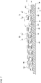
- Fig. 7 is a cross-sectional view of the positioning apparatus 16 according to embodiment 2.
- the positioning apparatus 16 includes the upper unit 26 that includes the spherical body 46, the retainer part 48 and the upper plate part 50, the lower unit 28 that includes the lower plate part 58 and the guide part 60, and the tilting structure 44 that tilts the region of movement 62 relative to the horizontal plane HP to guide the upper unit 26 toward the reference position. Further, the positioning apparatus 16 includes the base plate 20 that supports the lower unit 28.
- the base plate 20 of this embodiment includes a graded change part 68 in which the thickness 20T of the part that overlaps the region of movement 62 in the vertical direction is progressively smaller from one end of the region of movement 62 toward the other.
- the thickness 20T is progressively smaller from the side of the exit frame 24 toward the entrance frame 22 over the entirety of the base plate 20. Therefore, the graded change part 68 is provided over the entirety of the base plate 20. Provision of the graded change part 68 tilts the upper surface of the base plate 20 relative to the horizontal plane HP.
- the lower plate part 58 is fixed to the upper surface of the base plate 20 so that the graded change part 68 also tilts the region of movement 62. Therefore, the tilting structure 44 of this embodiment is formed by the graded change part 68.
- the feature provides the same advantage as that of embodiment 1.
- Embodiment 3 shares common features with embodiment 1 except for the tilting structure 44.
- the following description of this embodiment highlights features different from those of embodiment 1, and the description of the common features will be simplified or omitted.
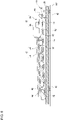
- Fig. 8 is a cross-sectional view of the positioning apparatus 16 according to embodiment 3.
- the positioning apparatus 16 includes the upper unit 26 that includes the spherical body 46, the retainer part 48 and the upper plate part 50, the lower unit 28 that includes the lower plate part 58 and the guide part 60, and the tilting structure 44 that tilts the region of movement 62 relative to the horizontal plane HP to guide the upper unit 26 toward the reference position.
- the lower unit 28 of this embodiment includes a leg part 70 that projects downward.
- the leg part 70 projects downward from the lower surface of the lower plate part 58.
- a plurality of leg parts 70 are provided at each of the edge of the lower plate part 58 toward the entrance frame 22 and the edge toward the exit frame 24.
- each leg part 70 is formed by an adjuster bolt, etc. and can extend or contract independently.
- the tilting structure 44 of this embodiment is formed by the leg part 70. By configuring some leg parts 70 of the tilting structure 44 to be longer than the other leg parts 70, the region of movement 62 is tilted relative to the horizontal plane HP. The feature provides the same advantage as that of embodiment 1.
- Embodiment 4 shares common features with embodiment 1 except for the tilting structure 44.
- the following description of this embodiment highlights features different from those of embodiment 1, and the description of the common features will be simplified or omitted.
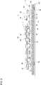
- Fig. 9 is a cross-sectional view of the positioning apparatus 16 according to embodiment 4.
- the positioning apparatus 16 includes the upper unit 26 that includes the spherical body 46, the retainer part 48 and the upper plate part 50, the lower unit 28 that includes the lower plate part 58 and the guide part 60, and the tilting structure 44 that tilts the region of movement 62 relative to the horizontal plane HP to guide the upper unit 26 toward the reference position.
- the lower plate part 58 of this embodiment includes a graded change part 72 in which the thickness 58T of the part that includes the region of movement 62 is progressively smaller from one end of the region of movement 62 toward the other.
- the thickness 58T is progressively smaller from the side of the exit frame 24 toward the side of the entrance frame 22 over the entirety of the lower plate part 58. Therefore, the graded change part 72 is provided over the entirety of the lower plate part 58. Provision of the graded change part 72 tilts the region of movement 62 relative to the horizontal plane HP. Therefore, the tilting structure 44 of this embodiment is formed by the graded change part 72.
- the feature provides the same advantage as that of embodiment 1.
- Embodiment 5 shares common features with embodiment 1 except that a biasing part is provided. The following description of this embodiment highlights features different from those of embodiment 1, and the description of the common features will be simplified or omitted.
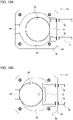
- Figs. 10A and 10B are plan views of the positioning apparatus 16 according to embodiment 5.
- Fig. 10A shows a state in which the carried object 1 (not shown) is mounted on the upper unit 26, and
- Fig. 10 B shows a state in which the carried object 1 is not mounted on the upper unit 26.
- the positioning apparatus 16 includes the upper unit 26 that includes the spherical body 46, the retainer part 48 and the upper plate part 50, the lower unit 28 that includes the lower plate part 58 and the guide part 60, and the tilting structure 44 that tilts the region of movement 62 relative to the horizontal plane HP to guide the upper unit 26 toward the reference position. Further, the positioning apparatus 16 includes the base plate 20 that supports the lower unit 28.
- the positioning apparatus 16 of this embodiment includes a biasing part 74 that biases the upper unit 26 toward the reference position.
- the biasing part 74 includes, by way of one example, a pair of spring cylinders 76 and a biasing plate 78 attached to the end of the pair of spring cylinders 76.
- Each spring cylinder 76 is slidably fixed to a region in the guide part 60 toward the exit frame 24 (the upper side of the tilt).
- the end of each spring cylinder 76 can advance and recede relative to the region of movement 62, and the built-in coil spring (not shown) biases the end in the direction of advancement toward the region of movement 62.
- the biasing plate 78 comes into contact with the side surface of the upper unit 26 and biases the upper unit 26 toward the entrance frame 22 (the lower side of the tilt) by a biasing force of the spring cylinder 76.
- the upper unit 26 When the carried object 1 is mounted on the positioning apparatus 16 and is drawn by the drawing mechanism 30 toward the exit frame 24, the upper unit 26 is displaced toward the exit frame 24 against the biasing force of the spring cylinder 6 ( Fig. 10A ). When the carried object 1 is removed from the positioning apparatus 16, the upper unit 16 is pressed by the biasing plate 78 toward the reference position ( Fig. 10B ). This ensures that the upper unit 26 is guided toward the reference position more properly.
Landscapes
- Engineering & Computer Science (AREA)
- General Engineering & Computer Science (AREA)
- Mechanical Engineering (AREA)
- Automatic Assembly (AREA)
- Container, Conveyance, Adherence, Positioning, Of Wafer (AREA)
- Details Of Measuring And Other Instruments (AREA)
Applications Claiming Priority (2)
| Application Number | Priority Date | Filing Date | Title |
|---|---|---|---|
| JP2019204647 | 2019-11-12 | ||
| PCT/JP2020/032982 WO2021095327A1 (fr) | 2019-11-12 | 2020-09-01 | Dispositif de positionnement |
Publications (3)
| Publication Number | Publication Date |
|---|---|
| EP4060671A1 true EP4060671A1 (fr) | 2022-09-21 |
| EP4060671A4 EP4060671A4 (fr) | 2023-01-04 |
| EP4060671B1 EP4060671B1 (fr) | 2025-04-02 |
Family
ID=75911425
Family Applications (1)
| Application Number | Title | Priority Date | Filing Date |
|---|---|---|---|
| EP20887791.0A Active EP4060671B1 (fr) | 2019-11-12 | 2020-09-01 | Dispositif de positionnement |
Country Status (5)
| Country | Link |
|---|---|
| US (1) | US11879587B2 (fr) |
| EP (1) | EP4060671B1 (fr) |
| JP (1) | JP7486093B2 (fr) |
| CN (1) | CN114641827B (fr) |
| WO (1) | WO2021095327A1 (fr) |
Families Citing this family (1)
| Publication number | Priority date | Publication date | Assignee | Title |
|---|---|---|---|---|
| CN216071927U (zh) * | 2021-11-15 | 2022-03-18 | 宁德时代新能源科技股份有限公司 | 定位装置及系统 |
Family Cites Families (30)
| Publication number | Priority date | Publication date | Assignee | Title |
|---|---|---|---|---|
| JPS58109238A (ja) * | 1981-12-21 | 1983-06-29 | Mitsutoyo Mfg Co Ltd | 位置出しテ−ブル装置 |
| US4749867A (en) * | 1985-04-30 | 1988-06-07 | Canon Kabushiki Kaisha | Exposure apparatus |
| JP2631392B2 (ja) * | 1988-06-30 | 1997-07-16 | キヤノン株式会社 | 位置決め装置 |
| DE4024557A1 (de) * | 1990-08-02 | 1992-02-06 | Heidenhain Gmbh Dr Johannes | Justiervorrichtung |
| US6112917A (en) * | 1998-11-23 | 2000-09-05 | Denstor Mobile Storage Systems, Inc. | Moveable file storage supporting apparatus |
| JP3066895B2 (ja) * | 1998-12-10 | 2000-07-17 | 株式会社東京精密 | 顕微鏡チルト機構 |
| JP4501174B2 (ja) * | 1999-05-31 | 2010-07-14 | ソニー株式会社 | 基板位置決め装置および基板貼り合わせ装置 |
| JP2001253536A (ja) * | 2000-03-09 | 2001-09-18 | Hirata Corp | 基板移載ロボット装置 |
| JP2004151839A (ja) * | 2002-10-29 | 2004-05-27 | Matsushita Electric Ind Co Ltd | 位置決めテーブル |
| JP4226955B2 (ja) * | 2003-06-13 | 2009-02-18 | 大日本スクリーン製造株式会社 | 基板の位置決め装置 |
| JP4443343B2 (ja) * | 2003-09-12 | 2010-03-31 | 株式会社井口機工製作所 | 位置決めステージ用支持ユニット及びその取付構造 |
| JP4476764B2 (ja) * | 2004-03-26 | 2010-06-09 | 富士フイルム株式会社 | 基板接合装置及び方法 |
| JP4895518B2 (ja) * | 2005-03-22 | 2012-03-14 | オリンパス株式会社 | 基板保持装置及び基板の保持方法 |
| JP2006329895A (ja) * | 2005-05-30 | 2006-12-07 | Dainippon Screen Mfg Co Ltd | 基板測定装置 |
| DE102005056449A1 (de) * | 2005-11-26 | 2007-08-02 | Alfing Kessler Sondermaschinen Gmbh | Werkstückhaltevorrichtung und damit ausgestattete Bearbeitungsmaschine |
| JP4797025B2 (ja) * | 2005-12-13 | 2011-10-19 | 高千穂 武田 | 搬送物の位置決め装置 |
| JP4882368B2 (ja) * | 2005-12-27 | 2012-02-22 | ウシオ電機株式会社 | ステージ装置 |
| US7516934B2 (en) * | 2006-02-24 | 2009-04-14 | Bio-Rad Laboratories, Inc. | Sample plate support of adjustable angular orientation |
| TWI457193B (zh) * | 2006-03-02 | 2014-10-21 | 住友重機械工業股份有限公司 | Stage device |
| JPWO2009113317A1 (ja) * | 2008-03-13 | 2011-07-21 | 株式会社ニコン | 基板ホルダ、基板ホルダユニット、基板搬送装置および基板貼り合わせ装置 |
| JP5488037B2 (ja) * | 2010-02-23 | 2014-05-14 | 村田機械株式会社 | 移載装置及びワーク載置装置 |
| JP5720186B2 (ja) * | 2010-11-04 | 2015-05-20 | 株式会社Ihi | ワーク移載装置 |
| US8813338B2 (en) * | 2011-03-11 | 2014-08-26 | Varian Semiconductor Equipment Associates, Inc. | Workpiece alignment device |
| JP6304536B2 (ja) | 2013-10-16 | 2018-04-04 | Smc株式会社 | ワーク位置決め装置 |
| JP5666041B1 (ja) * | 2013-10-17 | 2015-02-04 | 株式会社エムエイチセンター | R−θテーブル装置及びメネジの加工装置 |
| DE102016106936A1 (de) * | 2016-04-14 | 2017-10-19 | F. Zimmermann Gmbh | Positioniervorrichtung, insbesondere Werkzeugpositioniervorrichtung, für ein Bearbeitungszentrum und Bearbeitungszentrum mit dieser |
| US10337667B2 (en) * | 2016-07-11 | 2019-07-02 | Dyno Equipment, Inc. | Modular motorized slider system |
| JP2019010692A (ja) * | 2017-06-29 | 2019-01-24 | 日本電産サンキョー株式会社 | 産業用ロボットのハンドおよび産業用ロボット |
| US11014216B2 (en) * | 2017-10-27 | 2021-05-25 | Aida Engineering, Ltd. | Workpiece holding tool changing system for a workpiece conveying apparatus of a transfer press machine |
| US11630374B2 (en) * | 2018-01-09 | 2023-04-18 | Light-Path, Llc | Production equipment support assembly |
-
2020
- 2020-09-01 EP EP20887791.0A patent/EP4060671B1/fr active Active
- 2020-09-01 US US17/775,476 patent/US11879587B2/en active Active
- 2020-09-01 WO PCT/JP2020/032982 patent/WO2021095327A1/fr not_active Ceased
- 2020-09-01 JP JP2021555910A patent/JP7486093B2/ja active Active
- 2020-09-01 CN CN202080076033.8A patent/CN114641827B/zh active Active
Also Published As
| Publication number | Publication date |
|---|---|
| US20220397231A1 (en) | 2022-12-15 |
| EP4060671B1 (fr) | 2025-04-02 |
| WO2021095327A1 (fr) | 2021-05-20 |
| US11879587B2 (en) | 2024-01-23 |
| JP7486093B2 (ja) | 2024-05-17 |
| JPWO2021095327A1 (fr) | 2021-05-20 |
| CN114641827A (zh) | 2022-06-17 |
| CN114641827B (zh) | 2023-03-07 |
| EP4060671A4 (fr) | 2023-01-04 |
Similar Documents
| Publication | Publication Date | Title |
|---|---|---|
| US5711647A (en) | Method of and apparatus for locating and orientating a part on a gripper and transferring it to a tool while maintaining location and orientation on the tool | |
| US8973910B2 (en) | Positioning apparatus | |
| US9334935B2 (en) | Moving mechanism, electronic component transport device, electronic component inspection device | |
| US20140113019A1 (en) | System for passive alignment of surfaces | |
| EP4060671B1 (fr) | Dispositif de positionnement | |
| JP6464128B2 (ja) | ワーク固定装置 | |
| CN105229363A (zh) | 支撑脚 | |
| JP6521678B2 (ja) | 基板支持装置、及び電子部品実装装置 | |
| US11491531B2 (en) | Workpiece conveyance device | |
| KR101747664B1 (ko) | 테이블 내측에 하부가 삽입된 구체들을 갖는 소재 위치 제어 장치 | |
| JP5950604B2 (ja) | ワークホルダ及びワークセット方法 | |
| JP2010132369A (ja) | 搬送物の位置決め装置 | |
| JP7671188B2 (ja) | グリップ装置及び部品実装装置 | |
| US5421696A (en) | Zero error Z-axis compliance robotic device and process | |
| JP6223728B2 (ja) | 支持治具 | |
| JP6305249B2 (ja) | ステージ装置 | |
| JP2005057241A (ja) | 重い機械のアライメントを補助する位置決め補助具および方法 | |
| JP2021079501A (ja) | 組立装置、及び物品の製造方法 | |
| US20240207988A1 (en) | Workpiece holding device and workpiece holding method | |
| US20240269893A1 (en) | Brick loading/unloading apparatus and method | |
| CN206298052U (zh) | 钢片中转装置 | |
| JP4785696B2 (ja) | 位置決めユニット | |
| JP2020179518A (ja) | スクライブヘッド及びスクライブ装置 | |
| JP2018158437A (ja) | 把持機構 | |
| JPH11263428A (ja) | 位置決め装置付受台 |
Legal Events
| Date | Code | Title | Description |
|---|---|---|---|
| STAA | Information on the status of an ep patent application or granted ep patent |
Free format text: STATUS: THE INTERNATIONAL PUBLICATION HAS BEEN MADE |
|
| PUAI | Public reference made under article 153(3) epc to a published international application that has entered the european phase |
Free format text: ORIGINAL CODE: 0009012 |
|
| STAA | Information on the status of an ep patent application or granted ep patent |
Free format text: STATUS: REQUEST FOR EXAMINATION WAS MADE |
|
| 17P | Request for examination filed |
Effective date: 20220426 |
|
| AK | Designated contracting states |
Kind code of ref document: A1 Designated state(s): AL AT BE BG CH CY CZ DE DK EE ES FI FR GB GR HR HU IE IS IT LI LT LU LV MC MK MT NL NO PL PT RO RS SE SI SK SM TR |
|
| A4 | Supplementary search report drawn up and despatched |
Effective date: 20221202 |
|
| RIC1 | Information provided on ipc code assigned before grant |
Ipc: H01M 4/00 20060101ALI20221128BHEP Ipc: H01L 21/67 20060101ALI20221128BHEP Ipc: G12B 5/00 20060101AFI20221128BHEP |
|
| DAV | Request for validation of the european patent (deleted) | ||
| DAX | Request for extension of the european patent (deleted) | ||
| GRAP | Despatch of communication of intention to grant a patent |
Free format text: ORIGINAL CODE: EPIDOSNIGR1 |
|
| STAA | Information on the status of an ep patent application or granted ep patent |
Free format text: STATUS: GRANT OF PATENT IS INTENDED |
|
| RIC1 | Information provided on ipc code assigned before grant |
Ipc: H01M 10/48 20060101ALN20241108BHEP Ipc: H01M 10/04 20060101ALN20241108BHEP Ipc: H01M 4/139 20100101ALN20241108BHEP Ipc: H01F 7/02 20060101ALN20241108BHEP Ipc: F16M 7/00 20060101ALI20241108BHEP Ipc: F16P 1/00 20060101ALI20241108BHEP Ipc: H01M 4/00 20060101ALI20241108BHEP Ipc: H01L 21/67 20060101ALI20241108BHEP Ipc: G12B 5/00 20060101AFI20241108BHEP |
|
| INTG | Intention to grant announced |
Effective date: 20241125 |
|
| GRAS | Grant fee paid |
Free format text: ORIGINAL CODE: EPIDOSNIGR3 |
|
| P01 | Opt-out of the competence of the unified patent court (upc) registered |
Free format text: CASE NUMBER: APP_2636/2025 Effective date: 20250116 |
|
| GRAA | (expected) grant |
Free format text: ORIGINAL CODE: 0009210 |
|
| STAA | Information on the status of an ep patent application or granted ep patent |
Free format text: STATUS: THE PATENT HAS BEEN GRANTED |
|
| P01 | Opt-out of the competence of the unified patent court (upc) registered |
Free format text: CASE NUMBER: APP_2636/2025 Effective date: 20250116 |
|
| AK | Designated contracting states |
Kind code of ref document: B1 Designated state(s): AL AT BE BG CH CY CZ DE DK EE ES FI FR GB GR HR HU IE IS IT LI LT LU LV MC MK MT NL NO PL PT RO RS SE SI SK SM TR |
|
| REG | Reference to a national code |
Ref country code: GB Ref legal event code: FG4D |
|
| REG | Reference to a national code |
Ref country code: CH Ref legal event code: EP |
|
| REG | Reference to a national code |
Ref country code: DE Ref legal event code: R096 Ref document number: 602020048898 Country of ref document: DE |
|
| REG | Reference to a national code |
Ref country code: IE Ref legal event code: FG4D |
|
| REG | Reference to a national code |
Ref country code: NL Ref legal event code: MP Effective date: 20250402 |
|
| PG25 | Lapsed in a contracting state [announced via postgrant information from national office to epo] |
Ref country code: NL Free format text: LAPSE BECAUSE OF FAILURE TO SUBMIT A TRANSLATION OF THE DESCRIPTION OR TO PAY THE FEE WITHIN THE PRESCRIBED TIME-LIMIT Effective date: 20250402 |
|
| REG | Reference to a national code |
Ref country code: AT Ref legal event code: MK05 Ref document number: 1782127 Country of ref document: AT Kind code of ref document: T Effective date: 20250402 |
|
| PG25 | Lapsed in a contracting state [announced via postgrant information from national office to epo] |
Ref country code: FI Free format text: LAPSE BECAUSE OF FAILURE TO SUBMIT A TRANSLATION OF THE DESCRIPTION OR TO PAY THE FEE WITHIN THE PRESCRIBED TIME-LIMIT Effective date: 20250402 Ref country code: PT Free format text: LAPSE BECAUSE OF FAILURE TO SUBMIT A TRANSLATION OF THE DESCRIPTION OR TO PAY THE FEE WITHIN THE PRESCRIBED TIME-LIMIT Effective date: 20250804 Ref country code: ES Free format text: LAPSE BECAUSE OF FAILURE TO SUBMIT A TRANSLATION OF THE DESCRIPTION OR TO PAY THE FEE WITHIN THE PRESCRIBED TIME-LIMIT Effective date: 20250402 |
|
| PGFP | Annual fee paid to national office [announced via postgrant information from national office to epo] |
Ref country code: DE Payment date: 20250919 Year of fee payment: 6 |
|
| REG | Reference to a national code |
Ref country code: LT Ref legal event code: MG9D |
|
| PG25 | Lapsed in a contracting state [announced via postgrant information from national office to epo] |
Ref country code: NO Free format text: LAPSE BECAUSE OF FAILURE TO SUBMIT A TRANSLATION OF THE DESCRIPTION OR TO PAY THE FEE WITHIN THE PRESCRIBED TIME-LIMIT Effective date: 20250702 Ref country code: GR Free format text: LAPSE BECAUSE OF FAILURE TO SUBMIT A TRANSLATION OF THE DESCRIPTION OR TO PAY THE FEE WITHIN THE PRESCRIBED TIME-LIMIT Effective date: 20250703 |
|
| PG25 | Lapsed in a contracting state [announced via postgrant information from national office to epo] |
Ref country code: PL Free format text: LAPSE BECAUSE OF FAILURE TO SUBMIT A TRANSLATION OF THE DESCRIPTION OR TO PAY THE FEE WITHIN THE PRESCRIBED TIME-LIMIT Effective date: 20250402 |
|
| PG25 | Lapsed in a contracting state [announced via postgrant information from national office to epo] |
Ref country code: BG Free format text: LAPSE BECAUSE OF FAILURE TO SUBMIT A TRANSLATION OF THE DESCRIPTION OR TO PAY THE FEE WITHIN THE PRESCRIBED TIME-LIMIT Effective date: 20250402 |
|
| PGFP | Annual fee paid to national office [announced via postgrant information from national office to epo] |
Ref country code: GB Payment date: 20250919 Year of fee payment: 6 |
|
| PG25 | Lapsed in a contracting state [announced via postgrant information from national office to epo] |
Ref country code: HR Free format text: LAPSE BECAUSE OF FAILURE TO SUBMIT A TRANSLATION OF THE DESCRIPTION OR TO PAY THE FEE WITHIN THE PRESCRIBED TIME-LIMIT Effective date: 20250402 |
|
| PG25 | Lapsed in a contracting state [announced via postgrant information from national office to epo] |
Ref country code: AT Free format text: LAPSE BECAUSE OF FAILURE TO SUBMIT A TRANSLATION OF THE DESCRIPTION OR TO PAY THE FEE WITHIN THE PRESCRIBED TIME-LIMIT Effective date: 20250402 |
|
| PGFP | Annual fee paid to national office [announced via postgrant information from national office to epo] |
Ref country code: FR Payment date: 20250922 Year of fee payment: 6 |
|
| PG25 | Lapsed in a contracting state [announced via postgrant information from national office to epo] |
Ref country code: RS Free format text: LAPSE BECAUSE OF FAILURE TO SUBMIT A TRANSLATION OF THE DESCRIPTION OR TO PAY THE FEE WITHIN THE PRESCRIBED TIME-LIMIT Effective date: 20250702 |
|
| PG25 | Lapsed in a contracting state [announced via postgrant information from national office to epo] |
Ref country code: IS Free format text: LAPSE BECAUSE OF FAILURE TO SUBMIT A TRANSLATION OF THE DESCRIPTION OR TO PAY THE FEE WITHIN THE PRESCRIBED TIME-LIMIT Effective date: 20250802 |
|
| PG25 | Lapsed in a contracting state [announced via postgrant information from national office to epo] |
Ref country code: LV Free format text: LAPSE BECAUSE OF FAILURE TO SUBMIT A TRANSLATION OF THE DESCRIPTION OR TO PAY THE FEE WITHIN THE PRESCRIBED TIME-LIMIT Effective date: 20250402 |
|
| REG | Reference to a national code |
Ref country code: DE Ref legal event code: R097 Ref document number: 602020048898 Country of ref document: DE |
|
| PG25 | Lapsed in a contracting state [announced via postgrant information from national office to epo] |
Ref country code: DK Free format text: LAPSE BECAUSE OF FAILURE TO SUBMIT A TRANSLATION OF THE DESCRIPTION OR TO PAY THE FEE WITHIN THE PRESCRIBED TIME-LIMIT Effective date: 20250402 Ref country code: SM Free format text: LAPSE BECAUSE OF FAILURE TO SUBMIT A TRANSLATION OF THE DESCRIPTION OR TO PAY THE FEE WITHIN THE PRESCRIBED TIME-LIMIT Effective date: 20250402 |
|
| PG25 | Lapsed in a contracting state [announced via postgrant information from national office to epo] |
Ref country code: CZ Free format text: LAPSE BECAUSE OF FAILURE TO SUBMIT A TRANSLATION OF THE DESCRIPTION OR TO PAY THE FEE WITHIN THE PRESCRIBED TIME-LIMIT Effective date: 20250402 |
|
| PG25 | Lapsed in a contracting state [announced via postgrant information from national office to epo] |
Ref country code: EE Free format text: LAPSE BECAUSE OF FAILURE TO SUBMIT A TRANSLATION OF THE DESCRIPTION OR TO PAY THE FEE WITHIN THE PRESCRIBED TIME-LIMIT Effective date: 20250402 |
|
| PG25 | Lapsed in a contracting state [announced via postgrant information from national office to epo] |
Ref country code: SK Free format text: LAPSE BECAUSE OF FAILURE TO SUBMIT A TRANSLATION OF THE DESCRIPTION OR TO PAY THE FEE WITHIN THE PRESCRIBED TIME-LIMIT Effective date: 20250402 |
|
| PG25 | Lapsed in a contracting state [announced via postgrant information from national office to epo] |
Ref country code: IT Free format text: LAPSE BECAUSE OF FAILURE TO SUBMIT A TRANSLATION OF THE DESCRIPTION OR TO PAY THE FEE WITHIN THE PRESCRIBED TIME-LIMIT Effective date: 20250402 |
|
| PLBE | No opposition filed within time limit |
Free format text: ORIGINAL CODE: 0009261 |
|
| STAA | Information on the status of an ep patent application or granted ep patent |
Free format text: STATUS: NO OPPOSITION FILED WITHIN TIME LIMIT |
|
| PG25 | Lapsed in a contracting state [announced via postgrant information from national office to epo] |
Ref country code: RO Free format text: LAPSE BECAUSE OF FAILURE TO SUBMIT A TRANSLATION OF THE DESCRIPTION OR TO PAY THE FEE WITHIN THE PRESCRIBED TIME-LIMIT Effective date: 20250402 |
|
| REG | Reference to a national code |
Ref country code: CH Ref legal event code: L10 Free format text: ST27 STATUS EVENT CODE: U-0-0-L10-L00 (AS PROVIDED BY THE NATIONAL OFFICE) Effective date: 20260211 |
|
| 26N | No opposition filed |
Effective date: 20260105 |
|
| REG | Reference to a national code |
Ref country code: CH Ref legal event code: H13 Free format text: ST27 STATUS EVENT CODE: U-0-0-H10-H13 (AS PROVIDED BY THE NATIONAL OFFICE) Effective date: 20260425 |