EP4060687A1 - Coupe-circuit de surtension - Google Patents
Coupe-circuit de surtension Download PDFInfo
- Publication number
- EP4060687A1 EP4060687A1 EP21163542.0A EP21163542A EP4060687A1 EP 4060687 A1 EP4060687 A1 EP 4060687A1 EP 21163542 A EP21163542 A EP 21163542A EP 4060687 A1 EP4060687 A1 EP 4060687A1
- Authority
- EP
- European Patent Office
- Prior art keywords
- active member
- surge arrester
- longitudinal axis
- cross
- housing
- Prior art date
- Legal status (The legal status is an assumption and is not a legal conclusion. Google has not performed a legal analysis and makes no representation as to the accuracy of the status listed.)
- Granted
Links
Images


Classifications
-
- H—ELECTRICITY
- H01—ELECTRIC ELEMENTS
- H01C—RESISTORS
- H01C7/00—Non-adjustable resistors formed as one or more layers or coatings; Non-adjustable resistors made from powdered conducting material or powdered semi-conducting material with or without insulating material
- H01C7/10—Non-adjustable resistors formed as one or more layers or coatings; Non-adjustable resistors made from powdered conducting material or powdered semi-conducting material with or without insulating material voltage responsive, i.e. varistors
- H01C7/12—Overvoltage protection resistors; Arresters
-
- H—ELECTRICITY
- H01—ELECTRIC ELEMENTS
- H01C—RESISTORS
- H01C1/00—Details
- H01C1/02—Housing; Enclosing; Embedding; Filling the housing or enclosure
- H01C1/022—Housing; Enclosing; Embedding; Filling the housing or enclosure the housing or enclosure being openable or separable from the resistive element
-
- H—ELECTRICITY
- H01—ELECTRIC ELEMENTS
- H01C—RESISTORS
- H01C1/00—Details
- H01C1/02—Housing; Enclosing; Embedding; Filling the housing or enclosure
- H01C1/028—Housing; Enclosing; Embedding; Filling the housing or enclosure the resistive element being embedded in insulation with outer enclosing sheath
-
- H—ELECTRICITY
- H01—ELECTRIC ELEMENTS
- H01C—RESISTORS
- H01C7/00—Non-adjustable resistors formed as one or more layers or coatings; Non-adjustable resistors made from powdered conducting material or powdered semi-conducting material with or without insulating material
- H01C7/10—Non-adjustable resistors formed as one or more layers or coatings; Non-adjustable resistors made from powdered conducting material or powdered semi-conducting material with or without insulating material voltage responsive, i.e. varistors
- H01C7/102—Varistor boundary, e.g. surface layers
Definitions
- the present disclosure relates to a surge arrester.
- a surge arrester is a device for protecting an electrical equipment from overvoltages caused by, e.g., lightning or switching operations.
- a surge arrester is connected to the conductor, typically just before it enters an interior of the equipment.
- the surge arrester is also connected to ground and functions by routing energy from an over-voltage transient to ground if one occurs, while isolating the conductor from ground at normal operating voltages. This is usually achieved through use of a varistor, which has substantially different resistances at different voltages.
- the varistor is arranged within a housing of the surge arrester.
- the varistor heats and an arc occurs in the surge arrester causing an increase in pressure within the housing of the arrester.
- the varistor breaks under such circumstances.
- US 4,463,405 A discloses a surge arrester including an outer porcelain housing and an ablative heat shield liner along with techniques for making the surge arrester break resistant.
- a blow out or relief valve is provided on at least one end of the arrester housing for venting internal pressure due to electrical arcing therein.
- a surge arrester comprising an elongate housing, an active member, and an enclosure.
- the elongate housing has an interior comprising an interior surface that extends along a longitudinal axis between a first end and a second end of said housing.
- the active member is arranged at least partially within the interior and extending along the longitudinal axis.
- the enclosure is fixed to or integrally formed with the housing and closes the interior at the first end.
- the enclosure comprises a predetermined breaking line.
- the pressure within the housing increases and the predetermined breaking line allows for a defined breaking of the enclosure. This may allow part of the enclosure to break off while the remaining part of the enclosure may stay connected to or formed with the housing.
- the active member may have a cross-section that extends, at least partly, radially beyond the breaking line.
- the cross-section of the active member is particularly a cross-section normal, i.e. perpendicular, to the longitudinal axis. Radially may be understood herein so as to refer to a direction generally perpendicular to the longitudinal axis.
- the active member may move, caused by the increased pressure, along the longitudinal axis towards the first end. However, this movement can be stopped since the active member has a cross-section that extends, at least partly, radially beyond the breaking line.
- an uncontrolled ejection of critical parts can be reliably prevented. In this manner the operational safety of the surge arrester is increased.
- the breaking line may extend around the longitudinal axis or an axis being parallel thereto, defining an inner enclosure portion and an outer enclosure portion.
- the inner enclosure portion is particularly a radially inner portion of the enclosure with respect to the longitudinal axis or an axis parallel thereto.
- the longitudinal axis intersects the inner enclosure portion.
- the outer enclosure portion is particularly a radially outer portion of the enclosure with respect to the longitudinal axis. The inner enclosure portion and the outer enclosure portion may solely be separated from each other by the predetermined breaking line.
- the design of the surge arrester is such that a pressure increase due to a short circuit event effectuates a breaking of the enclosure along the predetermined breaking line, such that the inner enclosure portion separates from the outer enclosure portion, wherein the outer enclosure portion remains connected to the housing, and wherein an opening in the outer enclosure portion is formed at the place where the inner enclosure portion has been located prior to the breaking.
- the surge arrester is particularly suitable if it is a medium voltage surge arrester.
- medium voltage is understood as indicating a voltage range between 1 kV to 70 kV.
- the surge arrester may be designed such that an axial movement of the active member along the longitudinal axis towards the first end, for example caused by a short circuit event, interferes with the outer enclosure portion of the enclosure. More specifically, the outer enclosure portion may be designed to stop the axial movement of the active member along the longitudinal axis towards the first end. Thus, a defined movement may be promoted while said movement can be stopped particularly reliable.
- the housing and the enclosure may be formed integral, i.e., as a one-piece element.
- the enclosure and the housing may be formed by separate parts.
- the enclosure is fixed to the housing in a fluid-tight or gas-tight manner.
- the inner surface of the housing may be coated by a coating layer comprising or consisting of an arc-quenching material, e.g., melamine, aromatic epoxy resin, linear aliphatic epoxy resin, aluminum hydroxide, or metal hydride.
- an arc-quenching material e.g., melamine, aromatic epoxy resin, linear aliphatic epoxy resin, aluminum hydroxide, or metal hydride.
- the enclosure may extend at least substantially perpendicular to the longitudinal axis.
- the breaking line and thus the radially inner end of the outer enclosure portion may be substantially ring-shaped.
- a stopping function of the outer enclosure portion can be achieved that is particularly uniform or symmetrical with respect to the longitudinal axis.
- other shapes may be chosen.
- the surge arrester may further comprise a first discharge electrode provided at the first end of the housing, and a second connection electrode for connection to an electrical equipment, wherein the second connection electrode is provided at the second end of the housing.
- the active member may extend along the longitudinal axis between the first discharge electrode and the second connection electrode.
- the active member may further comprise an insulation member, arranged at least partially within the interior of the housing.
- the insulation member may particularly comprise or be made from an electrically isolating material.
- the active member may comprise a first active member portion having a first cross-sectional extent, and a second active member portion having a second cross-sectional extent, the second cross-sectional extent extending radially beyond the first cross-sectional extent.
- a cross-sectional extent of the predetermined breaking line may be radially completely contained within the second cross-sectional extent.
- a shoulder may be provided at a transition from the first to the second active member portion.
- the first active member portion may be provided closer to the first end than the second active member portion.
- the shoulder may be a rib, preferably a circumferentially extending rib.
- the shoulder may be a radially extending protrusion, for example one or several radially extending protrusions.
- the shoulder may be formed by the insulation member.
- the second active member portion may be designed to break in case of a short circuit event.
- the relative cross-sections of the first active member portion and the inner enclosure portion may be such that the first mentioned cross-section may extend through the latter-mentioned, and that the cross section of the second active member portion is at least partly larger than that of the inner enclosure portion such that it may not extend through the opening resulting from the inner enclosure's breaking along the breaking line.
- the second active member portion may comprise an outer wall portion that is shaped cylindrically with respect to the longitudinal axis in such a way that a movement of the outer wall portion along the longitudinal axis is guided by the interior surface.
- different mating shapes allowing such guidance may be foreseen.
- the interior surface of the interior of the housing may be shaped at least partly cylindrical.
- the interior surface and the outer wall portion of the second active member portion may be shaped complementary to each other in such a way, that the second active member portion is guided by the interior surface during the movement of the active member along the longitudinal axis towards the first end.
- the predetermined breaking line may at least substantially be circular. This is advantageous, since it may allow for a particularly easy manufacture and good distribution of forces.
- the enclosure may support the active member, preferably by supporting the first discharge electrode.
- the surge arrester may further comprise a biased member that is arranged with respect to the longitudinal axis between the active member and the inner enclosure portion and that is biased in a direction parallel to the longitudinal axis. This may allow for a reliably positioning of the active member.
- the biased member may support a breaking of the enclosure along the breaking line in a short circuit event, particularly by transmitting respective forces to the inner enclosure portion.
- the biased member is arranged such that it causes a pressure acting against the active member directed along the longitudinal axis towards the second end of the housing.
- the biased member may, at least to a first approximation, be ring-shaped and arranged surrounding the longitudinal axis. This may allow for a particularly uniform distribution of pressure with respect to the longitudinal axis.
- the discharge electrode may be electrically and mechanically connected to the active member and extend through a through hole formed in the inner enclosure portion to the outside of the housing.
- the biased member may surround the discharge electrode.
- the present disclosure comprises the following aspects:
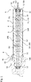
- Fig. 1 a is a schematic cross-sectional view of a surge arrester according to the present disclosure.
- the surge arrester comprises an elongate housing 2, a first discharge electrode 30, a second connection electrode 32, an active member 12.
- the elongate housing 2 has an interior 3 comprising an interior surface 4 that extends along a longitudinal axis L between a first end 6 and a second end 8 of the housing 2.
- the surge arrester according to this example is formed as a plug-in surge arrester, where the longitudinal axis L is parallel to a corresponding plug-in direction.
- the housing 2 comprises a fastening means 40 for fastening the housing 2 to an electrical equipment, e.g., a high-voltage installation.
- the first discharge electrode 30 is provided at the first end 6 of the housing 2.
- the first discharge electrode 30 may constitute a grounding terminal.
- the second connection electrode 32 is for connection to the electrical equipment.
- the second connection electrode 32 is provided at the second end 8 of the housing 2.
- the second electrode 32 may constitute a plug-in contact.
- the active member 12 is arranged at least partially within the interior 3 and extending along the longitudinal axis L between the first and second electrodes 30, 32.
- the active member 12 may comprise a non-linear, voltage-dependent resistance element, for example including at least one varistor.
- the active member 12 further comprises an insulation member 14, arranged at least partially within the interior 3.
- the insulation member 14 surrounds the resistance element of the active member 12 as seen within a normal cross-section normal, i.e., a cross-section perpendicular to the longitudinal axis L.
- the insulation member 14 may comprise an insulating cone portion 146 protruding along the longitudinal axis L beyond the second end 8 of the housing 2.
- the active member 12 When the surge arrester is fitted into the electrical equipment, the active member 12 may be plugged into a socket 50 of the electrical equipment and the housing 2 can be fixed to the electrical equipment, for example via the socket 50, by the fastening means 40, for example via a screw 42.
- the connection electrode 32 of the surge arrester is electrically connected to a current conductor of the electrical equipment.
- the insulating cone portion 146 and a mating insulating cone-shaped opening 52 of the socket 50 are pressed against each other. This achieves a suited plug-in connection which can withstand high loads and has a dielectrically high-grade insulation.
- the surge arrester further comprises an enclosure 10.
- the enclosure 10 is fixed to or integrally formed with the housing 2 and closes the interior 3 at the first end 6.
- said enclosure 10 is shown as being integrally formed with the housing 2. It may, however, also be a part sperate and affixed thereto.
- the enclosure 10 comprises a predetermined breaking line 16 extending, for example annular or circular, around the longitudinal axis L, defining a radially inner enclosure portion 102 and a radially outer enclosure portion 104. By a breaking of the breaking line 16, the inner enclosure portion 102 can be completely separated from the outer enclosure portion 104.
- the active member 12 has a normal cross-section, i.e., a cross-section perpendicular to the longitudinal axis L, that extends, at least partly, radially, i.e., radially outwardly from the longitudinal axis L beyond the breaking line 16.
- the normal cross-section of the active member 12 may vary in dependence on the position with respect to the longitudinal axis L.
- the active member 12 has at least at one position along the longitudinal axis L a normal cross-section that extends at least partly, radially beyond the breaking line 16.
- the active member 12 has at least at one position along the longitudinal axis L a normal cross-section that extends completely, i.e., in a circumferential manner or ring-shaped manner, radially beyond the breaking line 16. Practically speaking, a portion of the active member 12 that extends radially beyond the breaking line 16 will interfere, upon axial movement of the active member in the direction of the second end 6, with the outer portion 102 of the enclosure 10. Axial movement is therefore limited.
- the active member 12 may break, typically near the second end 8 of the housing 2, as illustrated in Fig. 2 and a portion of the active member 12 may be caused - by the increased pressure - to move along the longitudinal axis L toward the first end 6. Since the active member 12 has a normal cross-section that extends, at least partly, radially beyond the breaking line 16, this movement is stopped reliably by an interference between the active member 12 and the outer enclosure portion. In this manner, a welldefined pressure relief can be achieved, and an uncontrolled ejecting of critical parts can be prevented.
- the surge arrester is preferably designed such that an axial movement of the active member 12 along the longitudinal axis L towards the first end 6 that is caused by a fault condition, such as a short circuit event, interferes with the outer enclosure portion 104 of the enclosure 10.
- the outer enclosure portion 104 is designed to stop the axial movement of the active member 12 along the longitudinal axis L towards the first end 6.
- the outer enclosure portion 104 may be connected to the remainder of the housing 2 in an integral or one-piece manner.
- the enclosure may be formed by a separate part that is fixed to the housing 2 in a fluid-tight manner.
- the active member 12 may comprise a first active member portion 142 having a first cross-sectional extent, and a second active member portion 144 having a second cross-sectional extent, where the second cross-sectional extent extends radially beyond the first cross-sectional extent.
- the first cross-sectional extent and the second cross-sectional extent may be circular, respectively.
- the first active member portion 142 may have an outer surface that is shaped cylindrical with respect to the longitudinal axis L, having a first diameter D1
- the second active member portion 144 may have an outer surface that is shaped cylindrical with respect to the longitudinal L, having a second diameter D2, wherein second diameter D2 is larger than the first diameter.
- the predetermined breaking line 16 may be circular, having a diameter d, where the diameter d of the breaking line 16 is larger than the first diameter D1 and smaller than the second diameter D2, i.e., D1 ⁇ d ⁇ D2. In this way, the axial movement of the active member 12 along the longitudinal axis L can be reliably stopped by an interaction between the second active member portion 144 and the outer enclosure portion 104.
- a shoulder 148 is formed, for example having a conical surface.
- the cross-section of the active member 12, the first active member 142, and the second active member 144 is not necessarily circular. However, preferably, a cross-section, i.e. a circumferential extension of the first active member portion 142 extends through the cross-section of the inner enclosure portion 102, and a cross section of the second active member portion 144 is at least partly, preferably circumferentially completely larger than the cross-section of the inner enclosure portion 102 such that it may not extend therethrough.
- the second active member portion 144 comprises an outer wall portion 146 that is shaped cylindrically with respect to the longitudinal axis L in such a way that a movement of the outer wall portion 146 along the longitudinal axis L is guided by the interior surface 4.
- the interior surface 4 is preferably shaped cylindrically complementary to the outer wall portion 146 of the second active member portion 144 in such a way, that the second active member portion 144 is guided by the interior surface 4 during the movement of the active member 12 along the longitudinal axis L towards the first end 6 of the housing 2.
- the enclosure 10, particularly, the inner enclosure portion 102 supports the active member 12, directly or indirectly.
- the enclosure 10 may support the active member 12 by supporting the first discharge electrode 30.
- the surge arrester may further comprise a biased member 22, where the inner enclosure portion 102 supports the active part 12 (e.g., via the discharge electrode 30) by way of the biased member 22, directly or indirectly via further parts.
- the biased member 22 may be for example a spring.
- the biased member 22 is preferably arranged with respect to the longitudinal axis L between the active member 12 and the inner enclosure portion 102 and being biased in a direction parallel to the longitudinal axis L.
- the biased member 22 preferably is arranged such that it causes a pressure acting against the active member 12 directed along the longitudinal axis L towards the second end 8 of the housing 2.
- the biasing member 22 is a spring, it is preferably strongly compressed in the biasing state, such that it on the one hand exerts a suitable biasing force and on the other hand may directly transfer forces from the active member to the inner enclosure portion, resulting in breaking along the breaking line 16 in case of a fault.
- the biased member 22 is ring-shaped and arranged surrounding the longitudinal axis L. This allows for a particularly uniform flux of force between the inner enclosure portion 102 and the active member 12.
- the discharge electrode 30 is electrically and mechanically connected to the active member 12.
- the inner enclosure portion 102 shows a central through hole 26, where the discharge electrode 30 extends through the through hole 26.
- the discharge electrode 30 can be connected electrically easily from outside the housing 2 of the surge arrester.
- the biased member 22 surrounds the discharge electrode 30 as seen in a normal cross-section.
- the surge arrester may further comprise a centering element 60 for centering the first discharge electrode 30, arranged, at least partly between the inner enclosure portion 102 and the active member 12 or a portion of the discharge electrode 30.
- the inner enclosure portion 102 may support the active member 12 via the centering element 60.
- the inner enclosure portion 102 may support the discharge electrode 30 via both, the centering element 60 and the biased element 22.
- the centering element 60 preferably comprises a tube-shaped portion 62 for centering the discharge electrode 30 with respect to the longitudinal axis L.
- the tube-shaped portion 62 to this end extends through the throughhole 26 of the inner enclosure portion 102.
- the surge arrester may further comprise a breaking supporting member 70 that is designed to support a breaking of the enclosure 10 at the predetermined breaking line 16 in case of a short-circuit event or similar fault condition.
- the breaking support member 70 is fixed to the active member and/or the discharge electrode 30, directly or indirectly.
- the breaking supporting member 70 may comprise a sharp edge portion 72 that is preferably shaped complementary to the breaking line 16.
- the edge portion 72 preferably is arranged, as seen along the longitudinal axis L, at a small distance ⁇ from the breaking line 16.
- the small distance ⁇ may be less than 10% of the first diameter D1 of the first active member portion 142.
- force may be transmitted from the interior, particularly the active member 14, to the inner enclosure portion and/or the breaking line 16 in a number of different ways, directly and indirectly.
- this may be effected via a biasing member 22, via a centering element 60, via the discharge electrode 30, and/or via a breaking supporting member 70.
Landscapes
- Engineering & Computer Science (AREA)
- Microelectronics & Electronic Packaging (AREA)
- Physics & Mathematics (AREA)
- Electromagnetism (AREA)
- Thermistors And Varistors (AREA)
Priority Applications (4)
| Application Number | Priority Date | Filing Date | Title |
|---|---|---|---|
| EP21163542.0A EP4060687B1 (fr) | 2021-03-18 | 2021-03-18 | Coupe-circuit de surtension |
| CN202280021732.1A CN117083685A (zh) | 2021-03-18 | 2022-03-17 | 电涌放电器 |
| PCT/EP2022/056929 WO2022194987A1 (fr) | 2021-03-18 | 2022-03-17 | Parasurtenseur |
| US18/282,397 US12482585B2 (en) | 2021-03-18 | 2022-03-17 | Surge arrester |
Applications Claiming Priority (1)
| Application Number | Priority Date | Filing Date | Title |
|---|---|---|---|
| EP21163542.0A EP4060687B1 (fr) | 2021-03-18 | 2021-03-18 | Coupe-circuit de surtension |
Publications (2)
| Publication Number | Publication Date |
|---|---|
| EP4060687A1 true EP4060687A1 (fr) | 2022-09-21 |
| EP4060687B1 EP4060687B1 (fr) | 2025-07-23 |
Family
ID=75108282
Family Applications (1)
| Application Number | Title | Priority Date | Filing Date |
|---|---|---|---|
| EP21163542.0A Active EP4060687B1 (fr) | 2021-03-18 | 2021-03-18 | Coupe-circuit de surtension |
Country Status (4)
| Country | Link |
|---|---|
| US (1) | US12482585B2 (fr) |
| EP (1) | EP4060687B1 (fr) |
| CN (1) | CN117083685A (fr) |
| WO (1) | WO2022194987A1 (fr) |
Citations (5)
| Publication number | Priority date | Publication date | Assignee | Title |
|---|---|---|---|---|
| US2296708A (en) * | 1939-04-21 | 1942-09-22 | Line Material Co | Circuit interrupting device |
| FR1054738A (fr) * | 1951-04-24 | 1954-02-12 | D App Electr Sprecher & Schuh | Parafoudre inexplosible |
| GB1005040A (en) * | 1961-12-20 | 1965-09-22 | Hubbard & Company | Ground disconnect surge arrester |
| US4463405A (en) | 1981-02-19 | 1984-07-31 | Electric Power Research Institute, Inc. | Fail safe surge arrester |
| EP2124305A1 (fr) * | 2007-01-22 | 2009-11-25 | Swcc Showa Cable Systems Co., Ltd. | Dispositif d'arret |
Family Cites Families (23)
| Publication number | Priority date | Publication date | Assignee | Title |
|---|---|---|---|---|
| US4503414A (en) * | 1983-06-20 | 1985-03-05 | Sykes Huey P | Current interrupting lightning arrester isolator |
| US4663692A (en) * | 1985-06-27 | 1987-05-05 | Westinghouse Electric Corp. | Electrical surge arrester and disconnector |
| US4710847A (en) * | 1986-06-09 | 1987-12-01 | Juri Kortschinski | Current-limiting surge arrester disconnector |
| DE3815666A1 (de) | 1987-09-15 | 1989-03-30 | Pfisterer Elektrotech Karl | Steckbarer ueberspannungsableiter |
| US6430020B1 (en) * | 1998-09-21 | 2002-08-06 | Tyco Electronics Corporation | Overvoltage protection device including wafer of varistor material |
| ATE288127T1 (de) * | 2002-07-15 | 2005-02-15 | Abb Schweiz Ag | Steckbarer elektrischer apparat, insbesondere überspannungsableiter |
| CN200969260Y (zh) | 2006-09-26 | 2007-10-31 | 上海电瓷厂 | 可触摸式金属氧化物避雷器 |
| JP2008177508A (ja) | 2007-01-22 | 2008-07-31 | Swcc Showa Cable Systems Co Ltd | アレスタおよびアレスタの取付部 |
| JP2008178274A (ja) | 2007-01-22 | 2008-07-31 | Swcc Showa Cable Systems Co Ltd | アレスタおよびアレスタの取付部 |
| CN101465187B (zh) | 2009-01-04 | 2010-12-01 | 窦建中 | 肘型插拔式金属氧化物避雷器 |
| CN101707105B (zh) | 2009-11-16 | 2015-08-05 | 郭道林 | 可触摸拔插式避雷器 |
| JP5159852B2 (ja) | 2010-09-28 | 2013-03-13 | 株式会社東芝 | ノード、スイッチ及びシステム |
| DE102012008484A1 (de) | 2012-04-24 | 2013-10-24 | Pfisterer Kontaktsysteme Gmbh | Vorrichtung zum Ableiten einer elektrischen Überspannung |
| CN203070856U (zh) | 2012-11-08 | 2013-07-17 | 嘉兴市瑞嘉电气有限公司 | 插拔式金属外套避雷器 |
| CN203351322U (zh) | 2013-07-03 | 2013-12-18 | 山东泰开电力开关有限公司 | 户外35kV插拔式避雷器 |
| CN203521081U (zh) | 2013-10-10 | 2014-04-02 | 广东吉熙安电缆附件有限公司 | 一种内锥插拔式避雷器 |
| CN203659558U (zh) | 2014-01-22 | 2014-06-18 | 泰科电子(上海)有限公司 | 避雷器 |
| US10707678B2 (en) * | 2016-12-23 | 2020-07-07 | Ripd Research And Ip Development Ltd. | Overvoltage protection device including multiple varistor wafers |
| CN109215907B (zh) | 2017-06-30 | 2021-12-03 | 河南平高通用电气有限公司 | 罐式避雷器 |
| CN208607983U (zh) | 2018-05-10 | 2019-03-15 | 西门子股份公司 | 可插拔式避雷器 |
| CN208706344U (zh) | 2018-05-10 | 2019-04-05 | 西门子股份公司 | 可插拔式避雷器 |
| EP3782174A1 (fr) | 2018-06-15 | 2021-02-24 | Siemens Energy Global GmbH & Co. KG | Déflecteur de surtension à dispositif de décompression |
| CN208834824U (zh) | 2018-11-05 | 2019-05-07 | 西安神电电器有限公司 | 一种带防爆装置的屏蔽式插接避雷器 |
-
2021
- 2021-03-18 EP EP21163542.0A patent/EP4060687B1/fr active Active
-
2022
- 2022-03-17 US US18/282,397 patent/US12482585B2/en active Active
- 2022-03-17 WO PCT/EP2022/056929 patent/WO2022194987A1/fr not_active Ceased
- 2022-03-17 CN CN202280021732.1A patent/CN117083685A/zh active Pending
Patent Citations (5)
| Publication number | Priority date | Publication date | Assignee | Title |
|---|---|---|---|---|
| US2296708A (en) * | 1939-04-21 | 1942-09-22 | Line Material Co | Circuit interrupting device |
| FR1054738A (fr) * | 1951-04-24 | 1954-02-12 | D App Electr Sprecher & Schuh | Parafoudre inexplosible |
| GB1005040A (en) * | 1961-12-20 | 1965-09-22 | Hubbard & Company | Ground disconnect surge arrester |
| US4463405A (en) | 1981-02-19 | 1984-07-31 | Electric Power Research Institute, Inc. | Fail safe surge arrester |
| EP2124305A1 (fr) * | 2007-01-22 | 2009-11-25 | Swcc Showa Cable Systems Co., Ltd. | Dispositif d'arret |
Also Published As
| Publication number | Publication date |
|---|---|
| US12482585B2 (en) | 2025-11-25 |
| CN117083685A (zh) | 2023-11-17 |
| EP4060687B1 (fr) | 2025-07-23 |
| WO2022194987A1 (fr) | 2022-09-22 |
| US20240170188A1 (en) | 2024-05-23 |
Similar Documents
| Publication | Publication Date | Title |
|---|---|---|
| US5113306A (en) | Non-fragmenting arrester with staged pressure relief mechanism | |
| CN104335296B (zh) | 用于对过电压进行放电的设备 | |
| CN101529676B (zh) | 断路装置和断路装置的操纵方法 | |
| US5981893A (en) | Electrical switching device | |
| US4158869A (en) | Line protector | |
| CN109690891B (zh) | 用于电涌放电器的隔离开关装置及包括联接到所述隔离开关装置的电涌放电器的保护组件 | |
| US20070026713A1 (en) | Separable loadbreak connector and system with shock absorbent fault closure stop | |
| US10454251B2 (en) | Disconnector device for surge arrester and a protection assembly comprising a surge arrester connected to such a disconnector device | |
| US10236102B2 (en) | Lightning arrester | |
| US4208694A (en) | Line protector | |
| EP0966080B1 (fr) | Dispositif dérivateur de surtensions et méthode | |
| US12482585B2 (en) | Surge arrester | |
| US7154726B2 (en) | Pluggable electrical apparatus, in particular surge arrester | |
| WO2018191343A1 (fr) | Chapeaux pour composants de système de distribution d'énergie | |
| US1758181A (en) | Lightning arrester | |
| CA3179760C (fr) | Commutateur isole a l'air comprenant une longueur d'espace tres compacte | |
| US20240030698A1 (en) | Energy-limiting device for a surge arrester | |
| CN117153591A (zh) | 用于开关设备的开关 |
Legal Events
| Date | Code | Title | Description |
|---|---|---|---|
| PUAI | Public reference made under article 153(3) epc to a published international application that has entered the european phase |
Free format text: ORIGINAL CODE: 0009012 |
|
| STAA | Information on the status of an ep patent application or granted ep patent |
Free format text: STATUS: THE APPLICATION HAS BEEN PUBLISHED |
|
| AK | Designated contracting states |
Kind code of ref document: A1 Designated state(s): AL AT BE BG CH CY CZ DE DK EE ES FI FR GB GR HR HU IE IS IT LI LT LU LV MC MK MT NL NO PL PT RO RS SE SI SK SM TR |
|
| STAA | Information on the status of an ep patent application or granted ep patent |
Free format text: STATUS: REQUEST FOR EXAMINATION WAS MADE |
|
| 17P | Request for examination filed |
Effective date: 20230207 |
|
| RBV | Designated contracting states (corrected) |
Designated state(s): AL AT BE BG CH CY CZ DE DK EE ES FI FR GB GR HR HU IE IS IT LI LT LU LV MC MK MT NL NO PL PT RO RS SE SI SK SM TR |
|
| P01 | Opt-out of the competence of the unified patent court (upc) registered |
Effective date: 20230527 |
|
| RAP1 | Party data changed (applicant data changed or rights of an application transferred) |
Owner name: HITACHI ENERGY LTD |
|
| GRAP | Despatch of communication of intention to grant a patent |
Free format text: ORIGINAL CODE: EPIDOSNIGR1 |
|
| STAA | Information on the status of an ep patent application or granted ep patent |
Free format text: STATUS: GRANT OF PATENT IS INTENDED |
|
| INTG | Intention to grant announced |
Effective date: 20250228 |
|
| GRAS | Grant fee paid |
Free format text: ORIGINAL CODE: EPIDOSNIGR3 |
|
| GRAA | (expected) grant |
Free format text: ORIGINAL CODE: 0009210 |
|
| STAA | Information on the status of an ep patent application or granted ep patent |
Free format text: STATUS: THE PATENT HAS BEEN GRANTED |
|
| AK | Designated contracting states |
Kind code of ref document: B1 Designated state(s): AL AT BE BG CH CY CZ DE DK EE ES FI FR GB GR HR HU IE IS IT LI LT LU LV MC MK MT NL NO PL PT RO RS SE SI SK SM TR |
|
| REG | Reference to a national code |
Ref country code: GB Ref legal event code: FG4D |
|
| REG | Reference to a national code |
Ref country code: CH Ref legal event code: EP |
|
| REG | Reference to a national code |
Ref country code: DE Ref legal event code: R096 Ref document number: 602021034461 Country of ref document: DE |
|
| REG | Reference to a national code |
Ref country code: IE Ref legal event code: FG4D |
|
| REG | Reference to a national code |
Ref country code: SE Ref legal event code: TRGR |
|
| REG | Reference to a national code |
Ref country code: NL Ref legal event code: MP Effective date: 20250723 |
|
| PG25 | Lapsed in a contracting state [announced via postgrant information from national office to epo] |
Ref country code: PT Free format text: LAPSE BECAUSE OF FAILURE TO SUBMIT A TRANSLATION OF THE DESCRIPTION OR TO PAY THE FEE WITHIN THE PRESCRIBED TIME-LIMIT Effective date: 20251124 |
|
| PG25 | Lapsed in a contracting state [announced via postgrant information from national office to epo] |
Ref country code: NL Free format text: LAPSE BECAUSE OF FAILURE TO SUBMIT A TRANSLATION OF THE DESCRIPTION OR TO PAY THE FEE WITHIN THE PRESCRIBED TIME-LIMIT Effective date: 20250723 |
|
| REG | Reference to a national code |
Ref country code: AT Ref legal event code: MK05 Ref document number: 1817336 Country of ref document: AT Kind code of ref document: T Effective date: 20250723 |
|
| PG25 | Lapsed in a contracting state [announced via postgrant information from national office to epo] |
Ref country code: IS Free format text: LAPSE BECAUSE OF FAILURE TO SUBMIT A TRANSLATION OF THE DESCRIPTION OR TO PAY THE FEE WITHIN THE PRESCRIBED TIME-LIMIT Effective date: 20251123 |
|
| PG25 | Lapsed in a contracting state [announced via postgrant information from national office to epo] |
Ref country code: NO Free format text: LAPSE BECAUSE OF FAILURE TO SUBMIT A TRANSLATION OF THE DESCRIPTION OR TO PAY THE FEE WITHIN THE PRESCRIBED TIME-LIMIT Effective date: 20251023 |
|
| REG | Reference to a national code |
Ref country code: LT Ref legal event code: MG9D |
|
| PG25 | Lapsed in a contracting state [announced via postgrant information from national office to epo] |
Ref country code: AT Free format text: LAPSE BECAUSE OF FAILURE TO SUBMIT A TRANSLATION OF THE DESCRIPTION OR TO PAY THE FEE WITHIN THE PRESCRIBED TIME-LIMIT Effective date: 20250723 |
|
| PG25 | Lapsed in a contracting state [announced via postgrant information from national office to epo] |
Ref country code: FI Free format text: LAPSE BECAUSE OF FAILURE TO SUBMIT A TRANSLATION OF THE DESCRIPTION OR TO PAY THE FEE WITHIN THE PRESCRIBED TIME-LIMIT Effective date: 20250723 |
|
| PG25 | Lapsed in a contracting state [announced via postgrant information from national office to epo] |
Ref country code: HR Free format text: LAPSE BECAUSE OF FAILURE TO SUBMIT A TRANSLATION OF THE DESCRIPTION OR TO PAY THE FEE WITHIN THE PRESCRIBED TIME-LIMIT Effective date: 20250723 |
|
| PG25 | Lapsed in a contracting state [announced via postgrant information from national office to epo] |
Ref country code: GR Free format text: LAPSE BECAUSE OF FAILURE TO SUBMIT A TRANSLATION OF THE DESCRIPTION OR TO PAY THE FEE WITHIN THE PRESCRIBED TIME-LIMIT Effective date: 20251024 |
|
| PG25 | Lapsed in a contracting state [announced via postgrant information from national office to epo] |
Ref country code: LV Free format text: LAPSE BECAUSE OF FAILURE TO SUBMIT A TRANSLATION OF THE DESCRIPTION OR TO PAY THE FEE WITHIN THE PRESCRIBED TIME-LIMIT Effective date: 20250723 |
|
| PG25 | Lapsed in a contracting state [announced via postgrant information from national office to epo] |
Ref country code: BG Free format text: LAPSE BECAUSE OF FAILURE TO SUBMIT A TRANSLATION OF THE DESCRIPTION OR TO PAY THE FEE WITHIN THE PRESCRIBED TIME-LIMIT Effective date: 20250723 Ref country code: PL Free format text: LAPSE BECAUSE OF FAILURE TO SUBMIT A TRANSLATION OF THE DESCRIPTION OR TO PAY THE FEE WITHIN THE PRESCRIBED TIME-LIMIT Effective date: 20250723 |
|
| PG25 | Lapsed in a contracting state [announced via postgrant information from national office to epo] |
Ref country code: RS Free format text: LAPSE BECAUSE OF FAILURE TO SUBMIT A TRANSLATION OF THE DESCRIPTION OR TO PAY THE FEE WITHIN THE PRESCRIBED TIME-LIMIT Effective date: 20251023 |
|
| PG25 | Lapsed in a contracting state [announced via postgrant information from national office to epo] |
Ref country code: ES Free format text: LAPSE BECAUSE OF FAILURE TO SUBMIT A TRANSLATION OF THE DESCRIPTION OR TO PAY THE FEE WITHIN THE PRESCRIBED TIME-LIMIT Effective date: 20250723 |
|
| PG25 | Lapsed in a contracting state [announced via postgrant information from national office to epo] |
Ref country code: SM Free format text: LAPSE BECAUSE OF FAILURE TO SUBMIT A TRANSLATION OF THE DESCRIPTION OR TO PAY THE FEE WITHIN THE PRESCRIBED TIME-LIMIT Effective date: 20250723 |
|
| PGFP | Annual fee paid to national office [announced via postgrant information from national office to epo] |
Ref country code: SE Payment date: 20260319 Year of fee payment: 6 |
|
| PGFP | Annual fee paid to national office [announced via postgrant information from national office to epo] |
Ref country code: GB Payment date: 20260324 Year of fee payment: 6 |
|
| PG25 | Lapsed in a contracting state [announced via postgrant information from national office to epo] |
Ref country code: DK Free format text: LAPSE BECAUSE OF FAILURE TO SUBMIT A TRANSLATION OF THE DESCRIPTION OR TO PAY THE FEE WITHIN THE PRESCRIBED TIME-LIMIT Effective date: 20250723 |
|
| PGFP | Annual fee paid to national office [announced via postgrant information from national office to epo] |
Ref country code: DE Payment date: 20260319 Year of fee payment: 6 |
|
| PG25 | Lapsed in a contracting state [announced via postgrant information from national office to epo] |
Ref country code: IT Free format text: LAPSE BECAUSE OF FAILURE TO SUBMIT A TRANSLATION OF THE DESCRIPTION OR TO PAY THE FEE WITHIN THE PRESCRIBED TIME-LIMIT Effective date: 20250723 |
|
| PGFP | Annual fee paid to national office [announced via postgrant information from national office to epo] |
Ref country code: FR Payment date: 20260323 Year of fee payment: 6 |
|
| PG25 | Lapsed in a contracting state [announced via postgrant information from national office to epo] |
Ref country code: CZ Free format text: LAPSE BECAUSE OF FAILURE TO SUBMIT A TRANSLATION OF THE DESCRIPTION OR TO PAY THE FEE WITHIN THE PRESCRIBED TIME-LIMIT Effective date: 20250723 |
|
| PG25 | Lapsed in a contracting state [announced via postgrant information from national office to epo] |
Ref country code: SK Free format text: LAPSE BECAUSE OF FAILURE TO SUBMIT A TRANSLATION OF THE DESCRIPTION OR TO PAY THE FEE WITHIN THE PRESCRIBED TIME-LIMIT Effective date: 20250723 Ref country code: EE Free format text: LAPSE BECAUSE OF FAILURE TO SUBMIT A TRANSLATION OF THE DESCRIPTION OR TO PAY THE FEE WITHIN THE PRESCRIBED TIME-LIMIT Effective date: 20250723 |