EP4060702B1 - Leistungsschalter - Google Patents
Leistungsschalter Download PDFInfo
- Publication number
- EP4060702B1 EP4060702B1 EP22155591.5A EP22155591A EP4060702B1 EP 4060702 B1 EP4060702 B1 EP 4060702B1 EP 22155591 A EP22155591 A EP 22155591A EP 4060702 B1 EP4060702 B1 EP 4060702B1
- Authority
- EP
- European Patent Office
- Prior art keywords
- power switch
- housing assembly
- limiting portion
- shell
- outer collar
- Prior art date
- Legal status (The legal status is an assumption and is not a legal conclusion. Google has not performed a legal analysis and makes no representation as to the accuracy of the status listed.)
- Active
Links
Images



Classifications
-
- H—ELECTRICITY
- H01—ELECTRIC ELEMENTS
- H01H—ELECTRIC SWITCHES; RELAYS; SELECTORS; EMERGENCY PROTECTIVE DEVICES
- H01H19/00—Switches operated by an operating part which is rotatable about a longitudinal axis thereof and which is acted upon directly by a solid body external to the switch, e.g. by a hand
- H01H19/02—Details
- H01H19/04—Cases; Covers
-
- H—ELECTRICITY
- H01—ELECTRIC ELEMENTS
- H01H—ELECTRIC SWITCHES; RELAYS; SELECTORS; EMERGENCY PROTECTIVE DEVICES
- H01H19/00—Switches operated by an operating part which is rotatable about a longitudinal axis thereof and which is acted upon directly by a solid body external to the switch, e.g. by a hand
- H01H19/02—Details
- H01H19/10—Movable parts; Contacts mounted thereon
- H01H19/14—Operating parts, e.g. turn knob
Definitions
- the present disclosure relates to a power switch, and more particularly to a power switch applied to a light fixture.
- a power switch of a light fixture is provided in a rail structure having a conductive copper piece, so that relative positions of the power switch, the rail structure and the light fixture are fixed.
- JP 2001202860 A relating to a time switch comprises a housing assembly and a switch structure, and the switch structure is disposed in the housing assembly.
- CN 104 183 396 B discloses a switch according to the preamble of claim 1.
- a primary object of the present disclosure to provide a power switch, which solves, with a novel structural design of a housing assembly and a connection assembly, the issue of unadjustable relative positions of a conventional power switch and a light fixture.
- the present disclosure provides a power switch applied to a light fixture.
- the power switch includes a housing assembly, a switch structure and a connection assembly.
- the housing assembly includes an annular accommodating groove.
- the switch structure is disposed in the housing assembly.
- the connection assembly is disposed in the annular accommodating groove and includes a connecting element and an outer collar.
- the connecting element is connected to the light fixture and has an annular portion.
- the outer collar is sleeved at the annular portion of the connecting element and is accommodated in the annular accommodating groove.
- the connecting element has a first limiting portion that is provided on an outer side of the annular portion, and the outer collar has a second limiting portion that is provided on an inner side of the outer collar, wherein the second limiting portion corresponds to the first limiting portion.
- the first limiting portion and the second limiting portion are mutually abutted.
- the housing assembly includes a limiting slot that is provided on an inner wall of the annular accommodating groove, the outer collar has a third limiting portion that is provided on an outer side of the outer collar, wherein the third limiting portion is provided in the limiting slot.
- the third limiting portion moves in the limiting slot such that the connection assembly rotates relative to the housing assembly.
- the power switch further includes a line contact group disposed in the housing assembly.
- the line contact group includes a live line contact and a neutral line contact. One end of the live line contact and one end of the neutral line contact are respectively located on the other ends of the two conductive contacts.
- the live line contact and the neutral line contact are respectively in contact with the other ends of the two conductive contacts.
- the housing assembly includes a first shell and a second shell.
- the two contact openings are respectively located on sidewalls of the first shell and the second shell.
- the housing assembly further includes a fixing element connecting the first shell and the second shell.
- the power switch of the present disclosure includes a housing assembly, a switch structure and a connection assembly.
- the housing assembly includes an annular accommodating groove.
- the connection assembly includes connecting element and an outer collar. The outer collar is sleeved at an annular portion of the connecting element and accommodated in the annular accommodating groove, such that the connecting element is rotatable relative to the housing assembly.
- the connecting element is connected to the light fixture, so that the light fixture is rotatable along with the connecting element relative to the housing assembly, allowing relative positions between the power switching and the light fixture to be adjusted.
- the housing assembly includes a limiting slot located on an inner wall of the annular accommodating groove.
- the connection assembly has a first limiting portion located on an outer side of the annular portion.
- the outer collar has a second limiting portion and a third limiting portion.
- the second limiting portion is provided on an inner side of the outer collar, and the third limiting portion is provided on the outer side of the outer collar. With the second limiting portion corresponding to the first limiting portion, the third limiting portion is provided in the limiting slot.
- the number of rotations of the connecting element can be restricted, so as to prevent an issue of tangled wires of the light fixture caused by an excess number of rotations.
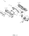
- a power switch 1 of this embodiment is applied to a light fixture (not shown).
- the power switch 1 includes a housing assembly 10, a switch structure 20 and a connection assembly 30, wherein the switch structure 20 is disposed in the housing assembly 10.
- the housing assembly 10 includes an annular accommodating groove 11 and a limiting slot 12, wherein the limiting slot 12 is provided on an inner wall of the annular accommodating groove 11.
- the housing assembly 10 includes a first shell 13 and a second shell 14.
- Each of the first shell 13 and the second shell 14 has a semicircular groove, and the two semicircular grooves together form the annular accommodating groove 11.
- the housing assembly 10 may also have two limiting slots 12, which are preferably arranged symmetrically on the inner wall of the annular accommodating groove 11.
- the semicircular groove of each of the first shell 13 and the second shell 14 may be provided with the limiting slot 12.
- the housing assembly 10 may further include a fixing element 15 connecting the first shell 13 and the second shell 14.
- the fixing element 15 of this embodiment is an L-shaped fastener for simultaneously fastening the first shell 13 and the second shell 14, thereby fixing the first shell 13 and the second shell 14.
- connection assembly 30 is disposed in the annular accommodating groove 11, and is rotatable in the annular accommodating groove 11.
- the connection assembly 30 of this embodiment includes a connecting element 31 and an outer collar 32.
- the connecting element 31 has an annular portion 311, and the outer collar 32 may be sleeved at the annular portion 311 of the connecting element 31. Accordingly, by accommodating the outer collar 32 in the annular accommodating groove 11, the connection assembly 30 may be disposed at the housing assembly 10. Since the annular accommodating groove 11, the annular portion 311 and the outer collar 32 are all annular structures, the connection assembly 30 is made rotatable relative to the housing assembly 10. Moreover, connection to the light fixture is achieved by the connecting element 31 of the connection assembly 30, so that the light fixture is also made rotatable along with the connecting element 31 relative to the housing assembly 10, further allowing relative positions between the power switch 1 and the light fixture to be adjusted.
- the outer collar 32 and the connecting element 31 are relatively rotatable; for example, the annular portion 311 rotates with the outer collar 32 until the first limiting portion 312 and the second limiting portion 321 become mutually abutted. With the structure of the first limiting portion 312 and the second limiting portion 321, the outer collar 32 and the connecting element 31 are allowed to rotate relatively by almost 360 degrees.
- the number of rotations of the connecting element 31 can be restricted, so as to prevent an issue of tangled wires of the light fixture caused by an excess number of rotations.
- FIG. 5A shows a schematic diagram of the power switch shown in FIG. 1 in an on state.
- FIG. 5B shows a schematic diagram of a switch structure and a line contact group in the power switch shown in FIG. 5A .
- FIG. 5C shows a schematic diagram of the power switch shown in FIG. 5A installed to a rail structure.
- FIG. 6A shows a schematic diagram of the power switch shown in FIG. 1 in an off state.
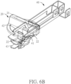
- FIG. 6B shows a schematic diagram of a switch structure and a line contact group in the power switch shown in FIG. 6A .
- the housing assembly 10 includes two contact openings 131 and 141, which are respectively located on sidewalls of the first shell 13 and the second shell 14.
- the switch structure 20 includes a knob 21 and two conductive contacts 22.
- the knob 21 is partially exposed from the housing assembly 10 for a user rotate so as to turn on or turn off the power switch 1 (the light fixture).
- the two conductive contacts 22 are disposed at the knob 21, so that the conductive contacts 22 are rotatable along with the knob 21.
- the conductive contacts 22 are located inside the housing assembly 10, and respective one end of the conductive contacts 22, along with the rotation of the knob 21, may be exposed on the outside of the housing assembly 10 from the contact openings 131 and 141, respectively.
- the power switch 1 further includes a line contact group 40 disposed in the housing assembly 10, and in this embodiment, the line contact group 40 is disposed inside the first shell 13.
- the line contact group 40 includes a live line contact 41, a neutral line contact 42 and a ground line contact 43.
- One end of the live line contact 41 and one end of the neutral line contact 42 respectively contacts with respective other ends of the two conductive contacts 22.
- respective one end of the conductive contacts 22 may be exposed on the outside of the housing assembly 10 through the contact openings 131 and 141, and the respective other ends are close to the live line contact 41 or the neutral line contact 42.
- the power switch 1 of this embodiment may be installed to a rail structure 9 of the light fixture, wherein the rail structure 9 includes a conductive copper piece 91.
- the knob 21 may be rotated so as to drive the conductive contacts 22 to rotate.
- respective one end of the two conductive contacts 22 are exposed on the outside of the housing assembly 10 (as shown in FIG. 5A ) from the contact openings 131 and 141, respectively, and the respective other ends of the two conductive contacts 22 are in contact with the live line contact 41 and the neutral line contact 42, respectively (as shown in FIG. 5B ).
- the conductive contacts 22 are exposed on the outside of the housing assembly 10 from the contact openings 131 and 141, and can further contact with the conductive copper piece 91 of the rail structure 9 and be conducted (as shown in FIG. 5C ).
- the switch structure 20 when the switch structure 20 is in an on state, the respective one end of the two conductive contacts 22 are exposed on the outside of the housing assembly 10 from the contact openings 131 and 141, and are conducted with the conductive copper piece 91 of the rail structure 9.
- the knob 21 is rotated in reverse to drive the conductive contacts 22 to rotate in reverse, such that the respective one end of the two conductive contacts 22 enter the housing assembly 10 (as shown in FIG. 6A ) from contact openings 131 and 141, respectively, and the respective other ends of the conductive contacts 22 do not contact with the live line contact 41 and the neutral line contact 42 (as shown in FIG. 6B ).
- the switch structure 20 is in an off state, the respective one end of the two conductive contacts 22 enter the housing assembly 10 from the contact openings 131 and 141, respectively, and are not conducted with the conductive copper piece 91 of the rail structure 9.
- the power switch of the present disclosure includes a housing assembly, a switch structure and a connection assembly.
- the housing assembly includes an annular accommodating groove.
- the connection assembly includes connecting element and an outer collar. The outer collar is sleeved at an annular portion of the connecting element and accommodated in the annular accommodating groove, such that the connecting element is rotatable relative to the housing assembly.
- the connecting element is connected to the light fixture, so that the light fixture is rotatable along with the connecting element relative to the housing assembly, allowing relative positions between the power switching and the light fixture to be adjusted.
- the housing assembly includes a limiting slot located on an inner wall of the annular accommodating groove.
- the connection assembly has a first limiting portion located on an outer side of the annular portion.
- the outer collar has a second limiting portion and a third limiting portion.
- the second limiting portion is provided on an inner side of the outer collar, and the third limiting portion is provided on the outer side of the outer collar. With the second limiting portion corresponding to the first limiting portion, the third limiting portion is provided in the limiting slot.
- the number of rotations of the connecting element can be restricted, so as to prevent an issue of tangled wires of the light fixture caused by an excess number of rotations.
Landscapes
- Arrangement Of Elements, Cooling, Sealing, Or The Like Of Lighting Devices (AREA)
Claims (11)
- Stromschalter (1), der mit einer Beleuchtungsvorrichtung verbunden werden kann, wobei der Stromschalter (1) aufweist:eine Gehäusebaugruppe (10);eine Schalterstruktur (20), die in der Gehäusebaugruppe (10) angeordnet ist;dadurch gekennzeichnet, dassdie Gehäusebaugruppe (10) eine ringförmige Aufnahmenut (11) aufweist; und der Stromschalter (1) ferner aufweist:
eine Verbindungsbaugruppe (30), die an der ringförmigen Aufnahmenut (11) angeordnet ist, wobei die Verbindungsbaugruppe (30) aufweist:ein Verbindungselement (31), das angepasst ist, um mit der Beleuchtungsvorrichtung verbunden zu sein/werden, wobei das Verbindungselement (31) einen ringförmigen Abschnitt (311) hat; undeinen äußeren Kragen (32), der an den ringförmigen Abschnitt (311) des Verbindungselements (31) gehülst ist und in der ringförmigen Aufnahmenut (11) aufgenommen ist. - Stromschalter (1) nach Anspruch 1, wobei das Verbindungselement (31) einen ersten Begrenzungsabschnitt (312) hat, der an einer Außenseite des ringförmigen Abschnitts (311) bereitgestellt ist, und der äußere Kragen (32) einen zweiten Begrenzungsabschnitt (321) hat, der an einer Innenseite des äußeren Kragens (32) bereitgestellt ist, wobei der zweite Begrenzungsabschnitt (321) zu dem ersten Begrenzungsabschnitt (312) korrespondiert.
- Stromschalter (1) nach Anspruch 2, wobei, wenn der äußere Kragen (32) und das Verbindungselement (31) relativ zueinander zu einer vorbestimmten Position gedreht sind/werden, der erste Begrenzungsabschnitt (312) und der zweite Begrenzungsabschnitt (321) gegenseitig gegeneinanderstoßen.
- Stromschalter (1) nach Anspruch 2, wobei die Gehäusebaugruppe (10) eine Begrenzungsaussparung (12) aufweist, die an einer Innenwand der ringförmigen Aufnahmenut (11) bereitgestellt ist, und der äußere Kragen (32) einen dritten Begrenzungsabschnitt (322) hat, der an einer Außenseite des äußeren Kragens (32) bereitgestellt ist, wobei der dritte Begrenzungsabschnitt (322) in der Begrenzungsaussparung (12) bereitgestellt ist.
- Stromschalter (1) nach Anspruch 4, wobei sich der dritte Begrenzungsabschnitt (322) in der Begrenzungsaussparung (12) bewegt, sodass sich die Verbindungsbaugruppe (30) relativ zu der Gehäusebaugruppe (10) dreht.
- Stromschalter (1) nach Anspruch 1, wobei die Gehäusebaugruppe (10) zwei Kontaktöffnungen (131, 141) aufweist, die Schalterstruktur (20) einen Knopf (21) und zwei leitfähige Kontakte (22) aufweist, wobei die zwei leitfähigen Kontakte (22) an dem Knopf (21) bereitgestellt sind, und, wenn die Schalterstruktur (20) in einem eingeschalteten Zustand ist, jeweils ein Ende jedes der zwei leitfähigen Kontakte (22) an einem Äußeren der Gehäusebaugruppe (10) von den Kontaktöffnungen (131, 141) freigelegt ist.
- Stromschalter (1) nach Anspruch 6, welcher ferner aufweist:
eine Leitung-Kontakt-Gruppe (40), die an der Gehäusebaugruppe (10) angeordnet ist, wobei die Leitung-Kontakt-Gruppe (40) einen spannungsführenden Leitungskontakt (41) und einen neutralen Leitungskontakt (42) aufweist, wobei ein Ende des spannungsführenden Leitungskontakts (41) und ein Ende des neutralen Leitungskontakts (42) entsprechend zugeordnet an den anderen Enden der zwei leitfähigen Kontakte (22) positioniert sind. - Stromschalter (1) nach Anspruch 7, wobei, wenn die Schalterstruktur (20) in einem eingeschalteten Zustand ist, der spannungsführende Leitungskontakt (41) und der neutrale Leitungskontakt (42) jeweils in Kontakt mit den anderen Enden der zwei leitfähigen Kontakte (22) sind.
- Stromschalter (1) nach Anspruch 6, wobei die Gehäusebaugruppe (10) eine erste Schale (13) und eine zweite Schale (14) aufweist.
- Stromschalter (1) nach Anspruch 9, wobei die zwei Kontaktöffnungen (131, 141) entsprechend zugeordnet an Seitenwänden der ersten Schale (13) und der zweiten Schale (14) angeordnet sind.
- Stromschalter (1) nach Anspruch 9, wobei die Gehäusebaugruppe (10) ferner ein Befestigungselement (15) aufweist, das die erste Schale (13) und die zweite Schale (14) verbindet.
Applications Claiming Priority (1)
| Application Number | Priority Date | Filing Date | Title |
|---|---|---|---|
| TW110203020U TWM617227U (zh) | 2021-03-19 | 2021-03-19 | 電源開關 |
Publications (2)
| Publication Number | Publication Date |
|---|---|
| EP4060702A1 EP4060702A1 (de) | 2022-09-21 |
| EP4060702B1 true EP4060702B1 (de) | 2024-11-20 |
Family
ID=78779159
Family Applications (1)
| Application Number | Title | Priority Date | Filing Date |
|---|---|---|---|
| EP22155591.5A Active EP4060702B1 (de) | 2021-03-19 | 2022-02-08 | Leistungsschalter |
Country Status (3)
| Country | Link |
|---|---|
| EP (1) | EP4060702B1 (de) |
| DK (1) | DK4060702T3 (de) |
| TW (1) | TWM617227U (de) |
Family Cites Families (2)
| Publication number | Priority date | Publication date | Assignee | Title |
|---|---|---|---|---|
| JP2001202860A (ja) * | 2000-01-21 | 2001-07-27 | Nakagawa Electric Ind Co Ltd | タイムスイッチ |
| CN104183396B (zh) * | 2014-09-15 | 2016-04-20 | 上海伊莱克斯实业有限公司 | 带指示灯型多档位转换开关 |
-
2021
- 2021-03-19 TW TW110203020U patent/TWM617227U/zh unknown
-
2022
- 2022-02-08 EP EP22155591.5A patent/EP4060702B1/de active Active
- 2022-02-08 DK DK22155591.5T patent/DK4060702T3/da active
Also Published As
| Publication number | Publication date |
|---|---|
| EP4060702A1 (de) | 2022-09-21 |
| DK4060702T3 (da) | 2025-01-20 |
| TWM617227U (zh) | 2021-09-21 |
Similar Documents
| Publication | Publication Date | Title |
|---|---|---|
| US4356360A (en) | Pull-to-turn switch | |
| EP1650838B1 (de) | Drehverbinder | |
| GB2209885A (en) | Reversible motor for an electric hand tool | |
| KR20110130422A (ko) | 회전형 스위치 | |
| US6116930A (en) | Rotary connection unit | |
| US20200194924A1 (en) | Rotatable Electric Plug | |
| US5904585A (en) | Rotary connector | |
| EP4060702A1 (de) | Leistungsschalter | |
| JP2000021273A (ja) | コラムスイッチ | |
| EP2075816B1 (de) | Schaltvorrichtung | |
| US6341969B1 (en) | Rotary connector | |
| KR101900897B1 (ko) | 회전 조작형 전자 부품의 베어링 구조 | |
| US4623763A (en) | Rotary multi-contact switch | |
| US5939684A (en) | Switch assembly having jog shuttle function and contact function | |
| US7474353B2 (en) | Digital camera and switch device | |
| JP3921591B2 (ja) | 電気掃除機 | |
| JP3713002B2 (ja) | プラグ可動式電源アダプタ | |
| JPH021005Y2 (de) | ||
| JP6948973B2 (ja) | 回転コネクタ | |
| TW201327609A (zh) | 旋轉操作型電子零件的軸承構造 | |
| KR200345671Y1 (ko) | 회로차단기의 부속장치 조작 레버 | |
| JP6681111B2 (ja) | ロータリースイッチ | |
| JP2017126465A (ja) | 回転コネクタ | |
| KR200183099Y1 (ko) | 전기 플러그 | |
| JP7317356B2 (ja) | 自動復帰機構ユニット |
Legal Events
| Date | Code | Title | Description |
|---|---|---|---|
| PUAI | Public reference made under article 153(3) epc to a published international application that has entered the european phase |
Free format text: ORIGINAL CODE: 0009012 |
|
| STAA | Information on the status of an ep patent application or granted ep patent |
Free format text: STATUS: THE APPLICATION HAS BEEN PUBLISHED |
|
| AK | Designated contracting states |
Kind code of ref document: A1 Designated state(s): AL AT BE BG CH CY CZ DE DK EE ES FI FR GB GR HR HU IE IS IT LI LT LU LV MC MK MT NL NO PL PT RO RS SE SI SK SM TR |
|
| STAA | Information on the status of an ep patent application or granted ep patent |
Free format text: STATUS: REQUEST FOR EXAMINATION WAS MADE |
|
| 17P | Request for examination filed |
Effective date: 20230106 |
|
| RBV | Designated contracting states (corrected) |
Designated state(s): AL AT BE BG CH CY CZ DE DK EE ES FI FR GB GR HR HU IE IS IT LI LT LU LV MC MK MT NL NO PL PT RO RS SE SI SK SM TR |
|
| GRAP | Despatch of communication of intention to grant a patent |
Free format text: ORIGINAL CODE: EPIDOSNIGR1 |
|
| STAA | Information on the status of an ep patent application or granted ep patent |
Free format text: STATUS: GRANT OF PATENT IS INTENDED |
|
| INTG | Intention to grant announced |
Effective date: 20240617 |
|
| P01 | Opt-out of the competence of the unified patent court (upc) registered |
Free format text: CASE NUMBER: APP_50266/2024 Effective date: 20240904 |
|
| GRAS | Grant fee paid |
Free format text: ORIGINAL CODE: EPIDOSNIGR3 |
|
| GRAA | (expected) grant |
Free format text: ORIGINAL CODE: 0009210 |
|
| STAA | Information on the status of an ep patent application or granted ep patent |
Free format text: STATUS: THE PATENT HAS BEEN GRANTED |
|
| AK | Designated contracting states |
Kind code of ref document: B1 Designated state(s): AL AT BE BG CH CY CZ DE DK EE ES FI FR GB GR HR HU IE IS IT LI LT LU LV MC MK MT NL NO PL PT RO RS SE SI SK SM TR |
|
| REG | Reference to a national code |
Ref country code: GB Ref legal event code: FG4D |
|
| REG | Reference to a national code |
Ref country code: CH Ref legal event code: EP |
|
| REG | Reference to a national code |
Ref country code: DE Ref legal event code: R096 Ref document number: 602022007778 Country of ref document: DE |
|
| REG | Reference to a national code |
Ref country code: IE Ref legal event code: FG4D |
|
| REG | Reference to a national code |
Ref country code: SE Ref legal event code: TRGR |
|
| REG | Reference to a national code |
Ref country code: DK Ref legal event code: T3 Effective date: 20250117 |
|
| REG | Reference to a national code |
Ref country code: LT Ref legal event code: MG9D |
|
| REG | Reference to a national code |
Ref country code: NL Ref legal event code: MP Effective date: 20241120 |
|
| PG25 | Lapsed in a contracting state [announced via postgrant information from national office to epo] |
Ref country code: IS Free format text: LAPSE BECAUSE OF FAILURE TO SUBMIT A TRANSLATION OF THE DESCRIPTION OR TO PAY THE FEE WITHIN THE PRESCRIBED TIME-LIMIT Effective date: 20250320 Ref country code: HR Free format text: LAPSE BECAUSE OF FAILURE TO SUBMIT A TRANSLATION OF THE DESCRIPTION OR TO PAY THE FEE WITHIN THE PRESCRIBED TIME-LIMIT Effective date: 20241120 Ref country code: PT Free format text: LAPSE BECAUSE OF FAILURE TO SUBMIT A TRANSLATION OF THE DESCRIPTION OR TO PAY THE FEE WITHIN THE PRESCRIBED TIME-LIMIT Effective date: 20250320 |
|
| PG25 | Lapsed in a contracting state [announced via postgrant information from national office to epo] |
Ref country code: FI Free format text: LAPSE BECAUSE OF FAILURE TO SUBMIT A TRANSLATION OF THE DESCRIPTION OR TO PAY THE FEE WITHIN THE PRESCRIBED TIME-LIMIT Effective date: 20241120 Ref country code: NL Free format text: LAPSE BECAUSE OF FAILURE TO SUBMIT A TRANSLATION OF THE DESCRIPTION OR TO PAY THE FEE WITHIN THE PRESCRIBED TIME-LIMIT Effective date: 20241120 |
|
| REG | Reference to a national code |
Ref country code: AT Ref legal event code: MK05 Ref document number: 1744373 Country of ref document: AT Kind code of ref document: T Effective date: 20241120 |
|
| PG25 | Lapsed in a contracting state [announced via postgrant information from national office to epo] |
Ref country code: BG Free format text: LAPSE BECAUSE OF FAILURE TO SUBMIT A TRANSLATION OF THE DESCRIPTION OR TO PAY THE FEE WITHIN THE PRESCRIBED TIME-LIMIT Effective date: 20241120 |
|
| PG25 | Lapsed in a contracting state [announced via postgrant information from national office to epo] |
Ref country code: ES Free format text: LAPSE BECAUSE OF FAILURE TO SUBMIT A TRANSLATION OF THE DESCRIPTION OR TO PAY THE FEE WITHIN THE PRESCRIBED TIME-LIMIT Effective date: 20241120 |
|
| PG25 | Lapsed in a contracting state [announced via postgrant information from national office to epo] |
Ref country code: LV Free format text: LAPSE BECAUSE OF FAILURE TO SUBMIT A TRANSLATION OF THE DESCRIPTION OR TO PAY THE FEE WITHIN THE PRESCRIBED TIME-LIMIT Effective date: 20241120 Ref country code: GR Free format text: LAPSE BECAUSE OF FAILURE TO SUBMIT A TRANSLATION OF THE DESCRIPTION OR TO PAY THE FEE WITHIN THE PRESCRIBED TIME-LIMIT Effective date: 20250221 Ref country code: AT Free format text: LAPSE BECAUSE OF FAILURE TO SUBMIT A TRANSLATION OF THE DESCRIPTION OR TO PAY THE FEE WITHIN THE PRESCRIBED TIME-LIMIT Effective date: 20241120 |
|
| PG25 | Lapsed in a contracting state [announced via postgrant information from national office to epo] |
Ref country code: PL Free format text: LAPSE BECAUSE OF FAILURE TO SUBMIT A TRANSLATION OF THE DESCRIPTION OR TO PAY THE FEE WITHIN THE PRESCRIBED TIME-LIMIT Effective date: 20241120 |
|
| PG25 | Lapsed in a contracting state [announced via postgrant information from national office to epo] |
Ref country code: RS Free format text: LAPSE BECAUSE OF FAILURE TO SUBMIT A TRANSLATION OF THE DESCRIPTION OR TO PAY THE FEE WITHIN THE PRESCRIBED TIME-LIMIT Effective date: 20250220 |
|
| PG25 | Lapsed in a contracting state [announced via postgrant information from national office to epo] |
Ref country code: SM Free format text: LAPSE BECAUSE OF FAILURE TO SUBMIT A TRANSLATION OF THE DESCRIPTION OR TO PAY THE FEE WITHIN THE PRESCRIBED TIME-LIMIT Effective date: 20241120 |
|
| PG25 | Lapsed in a contracting state [announced via postgrant information from national office to epo] |
Ref country code: EE Free format text: LAPSE BECAUSE OF FAILURE TO SUBMIT A TRANSLATION OF THE DESCRIPTION OR TO PAY THE FEE WITHIN THE PRESCRIBED TIME-LIMIT Effective date: 20241120 |
|
| PG25 | Lapsed in a contracting state [announced via postgrant information from national office to epo] |
Ref country code: RO Free format text: LAPSE BECAUSE OF FAILURE TO SUBMIT A TRANSLATION OF THE DESCRIPTION OR TO PAY THE FEE WITHIN THE PRESCRIBED TIME-LIMIT Effective date: 20241120 |
|
| PG25 | Lapsed in a contracting state [announced via postgrant information from national office to epo] |
Ref country code: SK Free format text: LAPSE BECAUSE OF FAILURE TO SUBMIT A TRANSLATION OF THE DESCRIPTION OR TO PAY THE FEE WITHIN THE PRESCRIBED TIME-LIMIT Effective date: 20241120 |
|
| PG25 | Lapsed in a contracting state [announced via postgrant information from national office to epo] |
Ref country code: CZ Free format text: LAPSE BECAUSE OF FAILURE TO SUBMIT A TRANSLATION OF THE DESCRIPTION OR TO PAY THE FEE WITHIN THE PRESCRIBED TIME-LIMIT Effective date: 20241120 |
|
| PG25 | Lapsed in a contracting state [announced via postgrant information from national office to epo] |
Ref country code: IT Free format text: LAPSE BECAUSE OF FAILURE TO SUBMIT A TRANSLATION OF THE DESCRIPTION OR TO PAY THE FEE WITHIN THE PRESCRIBED TIME-LIMIT Effective date: 20241120 |
|
| REG | Reference to a national code |
Ref country code: DE Ref legal event code: R097 Ref document number: 602022007778 Country of ref document: DE |
|
| PG25 | Lapsed in a contracting state [announced via postgrant information from national office to epo] |
Ref country code: MC Free format text: LAPSE BECAUSE OF FAILURE TO SUBMIT A TRANSLATION OF THE DESCRIPTION OR TO PAY THE FEE WITHIN THE PRESCRIBED TIME-LIMIT Effective date: 20241120 |
|
| PLBE | No opposition filed within time limit |
Free format text: ORIGINAL CODE: 0009261 |
|
| STAA | Information on the status of an ep patent application or granted ep patent |
Free format text: STATUS: NO OPPOSITION FILED WITHIN TIME LIMIT |
|
| REG | Reference to a national code |
Ref country code: CH Ref legal event code: PL |
|
| PG25 | Lapsed in a contracting state [announced via postgrant information from national office to epo] |
Ref country code: LU Free format text: LAPSE BECAUSE OF NON-PAYMENT OF DUE FEES Effective date: 20250208 |
|
| PG25 | Lapsed in a contracting state [announced via postgrant information from national office to epo] |
Ref country code: CH Free format text: LAPSE BECAUSE OF NON-PAYMENT OF DUE FEES Effective date: 20250228 |
|
| 26N | No opposition filed |
Effective date: 20250821 |
|
| REG | Reference to a national code |
Ref country code: BE Ref legal event code: MM Effective date: 20250228 |
|
| PG25 | Lapsed in a contracting state [announced via postgrant information from national office to epo] |
Ref country code: FR Free format text: LAPSE BECAUSE OF NON-PAYMENT OF DUE FEES Effective date: 20250228 |
|
| PG25 | Lapsed in a contracting state [announced via postgrant information from national office to epo] |
Ref country code: BE Free format text: LAPSE BECAUSE OF NON-PAYMENT OF DUE FEES Effective date: 20250228 |
|
| PG25 | Lapsed in a contracting state [announced via postgrant information from national office to epo] |
Ref country code: IE Free format text: LAPSE BECAUSE OF NON-PAYMENT OF DUE FEES Effective date: 20250208 |
|
| PGFP | Annual fee paid to national office [announced via postgrant information from national office to epo] |
Ref country code: SE Payment date: 20260218 Year of fee payment: 5 |
|
| PGFP | Annual fee paid to national office [announced via postgrant information from national office to epo] |
Ref country code: NO Payment date: 20260217 Year of fee payment: 5 Ref country code: DK Payment date: 20260217 Year of fee payment: 5 Ref country code: DE Payment date: 20260120 Year of fee payment: 5 |
|
| PG25 | Lapsed in a contracting state [announced via postgrant information from national office to epo] |
Ref country code: CY Free format text: LAPSE BECAUSE OF FAILURE TO SUBMIT A TRANSLATION OF THE DESCRIPTION OR TO PAY THE FEE WITHIN THE PRESCRIBED TIME-LIMIT Effective date: 20241120 |
|
| PG25 | Lapsed in a contracting state [announced via postgrant information from national office to epo] |
Ref country code: TR Free format text: LAPSE BECAUSE OF FAILURE TO SUBMIT A TRANSLATION OF THE DESCRIPTION OR TO PAY THE FEE WITHIN THE PRESCRIBED TIME-LIMIT Effective date: 20241120 |
|
| PG25 | Lapsed in a contracting state [announced via postgrant information from national office to epo] |
Ref country code: LT Free format text: LAPSE BECAUSE OF FAILURE TO SUBMIT A TRANSLATION OF THE DESCRIPTION OR TO PAY THE FEE WITHIN THE PRESCRIBED TIME-LIMIT Effective date: 20241120 |