EP4061018A2 - Procédé, appareil, et programme de traitement de signal audio - Google Patents
Procédé, appareil, et programme de traitement de signal audio Download PDFInfo
- Publication number
- EP4061018A2 EP4061018A2 EP22162885.2A EP22162885A EP4061018A2 EP 4061018 A2 EP4061018 A2 EP 4061018A2 EP 22162885 A EP22162885 A EP 22162885A EP 4061018 A2 EP4061018 A2 EP 4061018A2
- Authority
- EP
- European Patent Office
- Prior art keywords
- sound source
- sound
- speaker
- virtual
- virtual sound
- Prior art date
- Legal status (The legal status is an assumption and is not a legal conclusion. Google has not performed a legal analysis and makes no representation as to the accuracy of the status listed.)
- Pending
Links
Images


Classifications
-
- H—ELECTRICITY
- H04—ELECTRIC COMMUNICATION TECHNIQUE
- H04S—STEREOPHONIC SYSTEMS
- H04S7/00—Indicating arrangements; Control arrangements, e.g. balance control
- H04S7/30—Control circuits for electronic adaptation of the sound field
- H04S7/308—Electronic adaptation dependent on speaker or headphone connection
-
- H—ELECTRICITY
- H04—ELECTRIC COMMUNICATION TECHNIQUE
- H04R—LOUDSPEAKERS, MICROPHONES, GRAMOPHONE PICK-UPS OR LIKE ACOUSTIC ELECTROMECHANICAL TRANSDUCERS; ELECTRIC HEARING AIDS; PUBLIC ADDRESS SYSTEMS
- H04R1/00—Details of transducers, loudspeakers or microphones
- H04R1/20—Arrangements for obtaining desired frequency or directional characteristics
- H04R1/32—Arrangements for obtaining desired frequency or directional characteristics for obtaining desired directional characteristic only
- H04R1/34—Arrangements for obtaining desired frequency or directional characteristics for obtaining desired directional characteristic only by using a single transducer with sound reflecting, diffracting, directing or guiding means
- H04R1/345—Arrangements for obtaining desired frequency or directional characteristics for obtaining desired directional characteristic only by using a single transducer with sound reflecting, diffracting, directing or guiding means for loudspeakers
-
- H—ELECTRICITY
- H04—ELECTRIC COMMUNICATION TECHNIQUE
- H04R—LOUDSPEAKERS, MICROPHONES, GRAMOPHONE PICK-UPS OR LIKE ACOUSTIC ELECTROMECHANICAL TRANSDUCERS; ELECTRIC HEARING AIDS; PUBLIC ADDRESS SYSTEMS
- H04R5/00—Stereophonic arrangements
- H04R5/02—Spatial or constructional arrangements of loudspeakers
-
- H—ELECTRICITY
- H04—ELECTRIC COMMUNICATION TECHNIQUE
- H04R—LOUDSPEAKERS, MICROPHONES, GRAMOPHONE PICK-UPS OR LIKE ACOUSTIC ELECTROMECHANICAL TRANSDUCERS; ELECTRIC HEARING AIDS; PUBLIC ADDRESS SYSTEMS
- H04R5/00—Stereophonic arrangements
- H04R5/04—Circuit arrangements, e.g. for selective connection of amplifier inputs/outputs to loudspeakers, for loudspeaker detection, or for adaptation of settings to personal preferences or hearing impairments
-
- H—ELECTRICITY
- H04—ELECTRIC COMMUNICATION TECHNIQUE
- H04S—STEREOPHONIC SYSTEMS
- H04S7/00—Indicating arrangements; Control arrangements, e.g. balance control
- H04S7/30—Control circuits for electronic adaptation of the sound field
- H04S7/302—Electronic adaptation of stereophonic sound system to listener position or orientation
- H04S7/303—Tracking of listener position or orientation
-
- H—ELECTRICITY
- H04—ELECTRIC COMMUNICATION TECHNIQUE
- H04S—STEREOPHONIC SYSTEMS
- H04S7/00—Indicating arrangements; Control arrangements, e.g. balance control
- H04S7/30—Control circuits for electronic adaptation of the sound field
- H04S7/305—Electronic adaptation of stereophonic audio signals to reverberation of the listening space
-
- H—ELECTRICITY
- H04—ELECTRIC COMMUNICATION TECHNIQUE
- H04S—STEREOPHONIC SYSTEMS
- H04S7/00—Indicating arrangements; Control arrangements, e.g. balance control
- H04S7/40—Visual indication of stereophonic sound image
-
- H—ELECTRICITY
- H04—ELECTRIC COMMUNICATION TECHNIQUE
- H04S—STEREOPHONIC SYSTEMS
- H04S2400/00—Details of stereophonic systems covered by H04S but not provided for in its groups
- H04S2400/11—Positioning of individual sound objects, e.g. moving airplane, within a sound field
-
- H—ELECTRICITY
- H04—ELECTRIC COMMUNICATION TECHNIQUE
- H04S—STEREOPHONIC SYSTEMS
- H04S2400/00—Details of stereophonic systems covered by H04S but not provided for in its groups
- H04S2400/13—Aspects of volume control, not necessarily automatic, in stereophonic sound systems
-
- H—ELECTRICITY
- H04—ELECTRIC COMMUNICATION TECHNIQUE
- H04S—STEREOPHONIC SYSTEMS
- H04S2420/00—Techniques used stereophonic systems covered by H04S but not provided for in its groups
- H04S2420/01—Enhancing the perception of the sound image or of the spatial distribution using head related transfer functions [HRTF's] or equivalents thereof, e.g. interaural time difference [ITD] or interaural level difference [ILD]
Definitions
- An embodiment of the present disclosure relates to an audio signal processing method and an audio signal processing apparatus that perform predetermined processing on a sound to be inputted from a sound source.
- a speaker disposed in the space localizes a sound image to a sound source.
- a sound processing apparatus disclosed in International Publication No. 2016/208406 outputs a sound of an audio object (a sound source) by two or more speakers near the audio object (the sound source).
- the sound processing apparatus disclosed in International Publication No. 2016/208406 calculates a gain of an audio signal to be outputted to each speaker by use of position information and sound image information on the audio object (the sound source).
- an object of an embodiment of the present disclosure is to clearly reproduce sound image localization in a virtual space.
- An audio signal processing method includes dividing a virtual sound source representing a reflected sound of a target acoustic space into (i) a first virtual sound source located between a position of a speaker and a position of a sound receiving point, the first virtual sound source representing a first sound source of the reflected sound of the target acoustic space, and (ii) a second virtual sound source located such that the speaker is disposed between the second virtual sound source and the sound receiving point, the second virtual sound source representing a second sound source of the reflected sound of the target acoustic space, and, only in a case of the first virtual sound source, moving a position of the first virtual sound source to a reproducible position based on the position of the speaker.
- An audio signal processing method is able to clearly reproduce sound image localization in a virtual space.
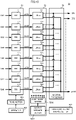
- FIG. 1 is a functional block diagram showing a configuration of an acoustic system including an audio signal processing apparatus according to an embodiment of the present disclosure.
- the mixer 60 is a summing mixer.
- the mixer 60 mixes the audio signals S1 to S96 of the sound sources OBJ1 to OBJ96, and generates a reverberant sound generation signal Sr.
- the mixer 60 outputs the reverberant sound generation signal Sr to the reverberant sound control signal generator 70.
- FIG. 5 is a functional block diagram showing an example of a configuration of a grouping portion 40.
- FIG. 6 is a flow chart showing a sound source grouping method.
- the sound source position detector 41 outputs the position coordinate of the sound sources OBJ1 to OBJ96 to the area determiner 42.
- FIG. 8A is a flow chart showing a sound source grouping method using a representative point.
- the area determiner 42 obtains coordinates information (a boundary coordinate) indicating a boundary line of each area Areal to Area8 from the area information on the plurality of areas Areal to Area8 (S1124). The area determiner 42 determines whether the position coordinate of the sound source to be determined for grouping is inside each area Areal to Area8 (S1125). For example, the area determiner 42 performs inside-outside determination of the sound source to an area, by use of the Crossing Number Algorithm. The area determiner 42, when a sound source is inside an area (S1125: YES), groups the sound source in this area (S1126).
- a boundary coordinate indicating a boundary line of each area Areal to Area8 from the area information on the plurality of areas Areal to Area8 (S1124).
- the area determiner 42 determines whether the position coordinate of the sound source to be determined for grouping is inside each area Areal to Area8 (S1125). For example, the area determiner 42 performs inside-outside determination of the sound source to an area
- the area determiner 42 detects the position coordinate of the sound source OBJ1, and obtains the coordinates information (the boundary coordinate) indicating a boundary line of the plurality of areas Areal to Area8.
- the area determiner 42 performs the inside-outside determination of the sound source OBJ1 to the plurality of areas Areal to Area8, from the position coordinate of the sound source OBJ1 and the boundary coordinate of the plurality of areas Areal to Area8.
- the area determiner 42 detects that the sound source OBJ1 is inside the area Areal.
- the area determiner 42 groups the sound source OBJ1 in the area Areal.
- the sound sources OBJ1 and OBJ4 are grouped in the area Areal.
- the matrix mixer 400 mixes the audio signal S1 of the sound source OBJ1 and the audio signal S4 of the sound source OBJ4, and generates and outputs an area-specific audio signal SA1 of the area Areal.
- the sound source OBJ2 is grouped in the area Area2.
- the matrix mixer 400 outputs the audio signal S2 of the sound source OBJ2 as an area-specific audio signal SA2 of the area Area2.
- the sound source OBJ3 is grouped in the area Area5.
- the matrix mixer 400 outputs the audio signal S3 of the sound source OBJ3 as an area-specific audio signal SA5 of the area Area5.
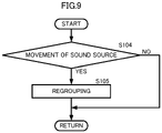
- the sound source position detector 41 detects movement of a sound source (S104).
- the sound source position detector 41 may detect the movement of a sound source by an operation input from a user, for example.
- the sound source position detector 41 may detect the movement of a sound source by continuously detecting a sound source position by the position detection sensor.
- the area determiner 42 regroups a moved sound source (S105).
- the sound source position detector 41 detects a position coordinate of the sound source after the movement, and outputs the position coordinate to the area determiner 42.
- the audio signal processing apparatus 10 By performing such processing, the audio signal processing apparatus 10, even when a sound source moves, is able to generate an initial reflected sound control signal according to the position of the sound source after the movement. As a result, the audio signal processing apparatus 10 is able to reproduce a change in the initial reflected sound according to the movement of a sound source, and, even when a sound source moves, is able to obtain clear sound image localization and rich spatial expansion according to the movement.
- the audio signal processing apparatus 10 is able to significantly reduce a discontinuous change in the initial reflected sound when the sound source moves. As a result, the audio signal processing apparatus 10, when the sound source moves, is able to change the initial reflected sound more smoothly according to the movement of the sound source.
- the matrix mixer 400 outputs the audio signals S1 to S96 of the plurality of sound sources OBJ1 to OBJ96, to the mixer 60.
- the mixer 60 sums the audio signals S1 to S96, and generates and outputs a reverberant sound generation signal Sr, to the reverberant sound control signal generator 70.
- the reverberant sound control signal generator 70 generates the reverberant sound control signals REV1 to REV64 by use of the reverberant sound generation signal Sr.
- the audio signal processing apparatus 10 is able to more clearly reproduce the movement of a sound source by a change in the initial reflected sound, while keeping the reverberant sound in the reproduction space constant, even when the sound source moves.
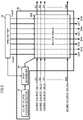
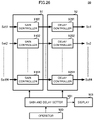
- FIG. 10 is a functional block diagram showing an example of a configuration of an initial reflected sound control signal generator 50.
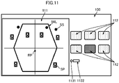
- FIG. 11 is a view showing an example of a GUI.
- the initial reflected sound control signal generator 50 includes a FIR filter circuit 51, an LDtap circuit 52, an addition processor 53, a tone setter 501, an imaginary sound source setter 502, and an operator 500.
- the LDtap circuit 52 amplifys and delays an inputted signal and outputs an amplified and delayed signal.
- the FIR filter circuit 51 includes a plurality of FIR filters 511 to 518.
- the LDtap circuit 52 includes a plurality of LDtaps 521 to 528, an output speaker setter 5201, and a coefficient setter 5202. It is to be noted that the order of connection between the FIR filter circuit 51 and the LDtap circuit 52 may be reversed.
- the operator 500 receives, from a user, designation information on a tone to be added to an initial reflected sound, and outputs the designation information to the tone setter 501.
- the designation information on a tone is information (information indicating filter characteristics) that designates low-frequency emphasis, high-frequency emphasis, volume of an initial reflected sound, attenuation characteristics of an initial reflected sound, or the like, for example.
- the operator 500 receives an operation through a GUI (Graphical User Interface) 100 as shown in FIG. 11 .
- GUI Graphic User Interface
- the GUI 100 includes a setting display window 111, a plurality of physical controllers 112, a knob 1131, and an adjustment value display window 1132.
- the setting display window 111 displays a shape of the virtual wall IWL of the virtual space set by the plurality of physical controllers 112 and the knob 1131.
- the setting display window 111 is able to display a position of a sound source SS, a position of a speaker SP, a position of a sound receiving point RP, and an axis of coordinates of the reproduction space that are separately set, together with the virtual wall IWL.
- the plurality of physical controllers 112 are linked to samples (various types of halls, rooms, and the like) of a previously set virtual space. It is to be noted that, although illustration is omitted, the plurality of physical controllers 112 may have an index (a hall name, for example) that clearly indicates the sample of the virtual space linked to each of the physical controllers 112.
- the GUI 100 receives various types of operations to adjust a tone.
- the GUI 100 includes the plurality of physical controllers 112, a physical controller for low frequencies, a physical controller for high frequencies, a physical controller for volume control, and a physical controller for attenuation characteristic adjustment, and receives operation through these physical controllers.
- the operator 500 detects this operation and sets the designation information on a tone according to such an operation.
- the operator 500 when receiving a selection of the plurality of physical controllers 112, obtains the designation information on a tone previously set to the virtual space linked to the physical controllers 112.
- the operator 500 when receiving an operation through the physical controller for low frequencies, the physical controller for high frequencies, the physical controller for volume control, the physical controller for attenuation characteristic adjustment, and the like, obtains designation information on a tone set by these physical controllers.
- the tone setter 501 sets the filter coefficient of the FIR filters 511 to 518 of the FIR filter circuit 51, based on the designation information on a tone. For example, the tone setter 501, when receiving the designation information on low-frequency emphasis, sets a filter coefficient obtained by boosting the low frequencies of the FIR filters 511 to 518 of the FIR filter circuit 51. In addition, the tone setter 501, when receiving the designation information on high-frequency emphasis, sets a filter coefficient obtained by boosting the high frequencies of the FIR filters 511 to 518 of the FIR filter circuit 51. The tone setter 501 outputs the set filter coefficient to the FIR filter circuit 51. It is to be noted that the tone setter 501 is also able to set and adjust a sampling frequency and a filter length not only as a filter coefficient but as filter characteristics.
- the area-specific audio signal SA5 is inputted to the FIR filter 515
- the area-specific audio signal SA6 is inputted to the FIR filter 516
- the area-specific audio signal SA7 is inputted to the FIR filter 517
- the area-specific audio signal SA8 is inputted to the FIR filter 518.
- the plurality of FIR filters 511 to 518 perform filter processing (a convolution operation) on each of the plurality of area-specific audio signals SA1 to SA8, with the filter coefficient and gain value that have been set by the tone setter 501.
- the plurality of FIR filters 511 to 518 generate area-specific audio signals SA1f to SA8f on which the filter processing has been performed.
- the FIR filter 511 performs the filter processing (the convolution operation) on the area-specific audio signal SA1, and generates the area-specific audio signal SA1f on which the filter processing has been performed, with the filter coefficient and gain value that have been set by the tone setter 501.
- the plurality of FIR filters 512 to 518 individually generate the area-specific audio signals SA2f to SA8f on which the filter processing has been performed, from the area-specific audio signals SA2 to SA8.
- the plurality of FIR filters 511 to 518 output the area-specific audio signals SA1f to SA8f on which the filter processing has been performed, to the plurality of LDtaps 521 to 528.
- the FIR filter 511 outputs the area-specific audio signal SA1f on which the filter processing has been performed, to the LDtap 521.
- the plurality of FIR filters 512 to 518 output the area-specific audio signals SA2f to SA8f on which the filter processing has been performed, to the plurality of LDtaps 522 to 528.
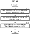
- FIG. 12 is a flow chart showing an example of processing of setting an imaginary sound source.
- the imaginary sound source setter 502 obtains the position coordinate of the sound receiving point in the reproduction space (S131).
- the imaginary sound source setter 502 obtains the position coordinate of the sound receiving point in the reproduction space by an operation input from a user, detection of a position by the position detection sensor, or the like.
- the imaginary sound source setter 502 obtains the geometrical shape of the virtual space (S132).
- the imaginary sound source setter 502 obtains the geometrical shape of the virtual space by an operation input from a user, or the like.
- the geometrical shape of the virtual space includes coordinates group indicating the shape of a wall disposed in the virtual space.
- the imaginary sound source setter 502 is connected to the GUI 100.
- the GUI 100 reads and obtains the geometrical shape of the virtual space linked to this physical controller 112.
- the GUI 100 obtains an adjustment value of this room size.
- the imaginary sound source setter 502 obtains a position coordinate of the geometrical shape of the virtual space of which the room size is set, based on each setting that the GUI 100 has obtained as described above. In addition, the imaginary sound source setter 502 obtains a position coordinate of the sound source SS, and a position coordinate of the sound receiving point (the center of a room (the center of the reproduction space)) RP. The imaginary sound source setter 502 sets an imaginary sound source, as shown below, by use of these pieces of obtained information.
- the imaginary sound source setter 502 matches a coordinate system of the reproduction space with a coordinate system of the virtual space.
- the imaginary sound source setter 502 sets the position coordinate of the imaginary sound source in the reproduction space, based on a concept using FIG. 4A and FIG. 4B by use of the position coordinate of the sound receiving point of the reproduction space, and the geometrical shape of the virtual space (S133).
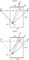
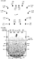
- FIG. 13A and FIG. 13B are views each showing an example of setting an imaginary sound source in a case in which geometrical shapes are different.
- FIG. 13A shows a square virtual wall IWL, in a plan view
- FIG. 13B shows a hexagonal virtual wall IWLh, in a plan view.
- FIG. 14A, FIG. 14B, and FIG. 14C are views showing an example of setting an imaginary sound source.
- FIG. 14A, FIG. 14B, and FIG. 14C are views showing a planar change in the imaginary sound source.
- FIG. 14B compared with FIG. 14A , shows a case in which the positions of the sound source SSa to the reference point (the sound receiving point RP) are the same and the sizes of the virtual space are different.
- FIG. 14C compared with FIG. 14A , shows a case in which the sizes of the virtual space are the same and the positional relationship between the reference point of the virtual space and the reference point (the sound receiving point) of the reproduction space changes (a case in which the center of a room of the reproduction space changes).
- the sizes (described as a virtual wall IWL in FIG. 14A and a virtual wall IWLc in FIG. 14B ) of the virtual space in the reproduction space are different, so that the distance and positional relationship between the sound source SSa being the origin of the imaginary sound source and the virtual wall are different.
- the positions of imaginary sound sources IS1a, IS2a, and IS3a that are set in a case of FIG. 14A are different from the positions of imaginary sound sources IS1c, IS2c, and IS3c that are set in FIG. 14B .
- the positional relationship between the reference point of the virtual space and the reference point RP changes, so that the position (the position of the imaginary sound source with respect to the sound receiving point RP and a speaker) of the imaginary sound source in the reproduction space is moved.
- the positions of the imaginary sound sources IS1a, IS2a, and IS3a that are set in a case of FIG. 14A are different from the positions of imaginary sound sources IS1as, IS2as, and IS3as that are set in a case of FIG. 14C .
- FIG. 15A and FIG. 15B show different heights of a ceiling.
- the distance (the height) from a virtual wall IWFL of a floor in the virtual wall IWL shown in FIG. 15A to a virtual wall IWCL of the ceiling is different from the distance (the height) from the virtual wall IWFL of the floor in a virtual wall IWLL shown in FIG. 15B to a virtual wall IWCLL of the ceiling.
- FIG. 15A As can be seen from a result of comparison between FIG. 15A and FIG. 15B , the heights of the ceiling are different, so that the distance and positional relationship between the sound source SSa being the origin of the imaginary sound source and the virtual walls IWCL and IWCLL of the ceiling are different. As a result, the position of an imaginary sound source IS1Ca set in a case of FIG. 15A is different from the position of an imaginary sound source IS1CaL set in a case of FIG. 15B .
- FIG. 15A and FIG. 15C show different shapes of a ceiling.
- the shape of the virtual wall IWCL of the ceiling in the virtual wall IWL shown in FIG. 15A is different from the shape of a virtual wall IWCLx of the ceiling in a virtual wall IWLx shown in FIG. 15C .
- the imaginary sound source setter 502 is able to optimally set the position of the imaginary sound source in the reproduction space, corresponding to the geometrical shape of the virtual space, and the positional relationship (such as a positional relationship between the reference points of the spaces, for example) between the reproduction space and the virtual space.
- the audio signal processing apparatus 10 is able to clarify the sound image localization of the initial reflected sound, corresponding to the position coordinate of a speaker in the reproduction space, the geometrical shape of the virtual space, and the positional relationship between the reproduction space and the virtual space.
- the imaginary sound source setter 502 outputs the position coordinate of the imaginary sound source set for each of the plurality of areas Areal to Area8, to the output speaker setter 5201 of the LDtap circuit 52.
- the output speaker setter 5201 sets an imaginary sound source IS that assigns for each speaker based on the position coordinate of the imaginary sound source IS, the position coordinate of the sound receiving point RP, and the position coordinates of the plurality of speakers SP1 to SP64.
- FIG. 16 is a flow chart showing processing of assigning an imaginary sound source to a speaker.
- the output speaker setter 5201 obtains the position coordinate of an imaginary sound source from the imaginary sound source setter 502 (S141) .
- the output speaker setter 5201 obtains the position coordinate of a sound receiving point in the reproduction space, for example, by an operation input from a user, or the like (S142) .
- the output speaker setter 5201 obtains the position coordinate of a plurality of speakers SP1 to SP64, for example, by an operation input from a user, or the like (S143).
- the output speaker setter 5201 sets an assigned region assigned to an imaginary sound source for each speaker, from the positional relationship between the sound receiving point RP in the reproduction space and the plurality of speakers SP1 to SP64 (S144).
- the output speaker setter 5201 sets an assigned region assigned to the imaginary sound source for each speaker as follows.
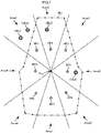
- FIG. 17A and FIG. 17B are views showing a concept of assigning an imaginary sound source to a speaker.
- FIG. 17A shows a concept of assignment using an azimuth ⁇
- FIG. 17B shows a concept of assignment using an elevation-depression angle ⁇ .
- the speaker SP1 will be described hereinafter as an example, the output speaker setter 5201 also sets an assigned region assigned to the other speakers SP2 to SP64 in the same manner.
- the output speaker setter 5201 sets an elevation-depression angle ⁇ expanding in a vertical direction perpendicular to a plane, with respect to the straight line (the dashed line in FIG. 17B ) described above.
- the elevation-depression angle ⁇ is an angle in the vertical direction (a direction perpendicular to the horizontal direction) to the straight line passing the sound receiving point RP and the speaker SP1.
- the output speaker setter 5201 sets a space closer to the speaker SP1 than to a boundary (a boundary plane to determine a horizontal area, a boundary plane to determine a vertical area) determined by this azimuth ⁇ and the elevation-depression angle ⁇ as an assigned region RGSP1 of the speaker SP1.
- the output speaker setter 5201 obtains the position coordinate of a plurality of imaginary sound sources IS (a plurality of imaginary sound sources ISa to ISg in a case of FIG. 17 ).
- the output speaker setter 5201 determines whether the plurality of imaginary sound sources ISa to ISg are in the assigned region RGSP1 by use of the position coordinate of the plurality of imaginary sound sources ISa to ISg and the coordinates indicating the assigned region RGSP1. This determination is able to be made by the same method as the method of the grouping to the area of the sound source described above.
- the output speaker setter 5201 by performing this determination processing, in a case shown in FIG. 14A, FIG. 14B, and FIG. 14C , for example, determines that the plurality of imaginary sound sources ISa, ISb, ISc, and ISd are inside the assigned region RGSP1 and determines that the plurality of imaginary sound sources ISe, ISf, and ISg are outside the assigned region RGSP1.
- the output speaker setter 5201 assigns the plurality of imaginary sound sources ISa, ISb, ISc, and ISd that are determined to be in the assigned region RGSP1, to the speaker SP1 (S145).
- the output speaker setter 5201 outputs assignment information on the plurality of imaginary sound sources to the plurality of speakers SP1 to SP64, to the coefficient setter 5202. In such a case, the output speaker setter 5201 outputs the position coordinate of the sound receiving point RP, the position coordinates of the plurality of speakers SP1 to SP64, and the position coordinate of the plurality of imaginary sound sources, with the assignment information, to the coefficient setter 5202.
- the azimuth ⁇ is 60 degrees, for example, and the elevation-depression angle ⁇ is 45 degrees, for example.
- the angular degree of these azimuth ⁇ and elevation-depression angle ⁇ is an example, and is able to be set and adjusted, for example, by an operation input from a user.
- the coefficient setter 5202 sets a tap coefficient to be given to the LDtaps 521 to 528 by use of the distance between the sound receiving point RP and the plurality of speakers SP1 to SP64, and the distance between the sound receiving point RP and the imaginary sound source IS.
- the tap coefficient to be given to the LDtaps 521 to 528 is a gain value and delay amount of the LDtaps 521 to 528.
- FIG. 18 is a flow chart showing LDtap coefficient setting processing.
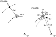
- FIG. 19A and FIG. 19B are views for illustrating a concept of coefficient setting.
- the coefficient setter 5202 calculates a distance (a speaker distance) between the sound receiving point PR and the plurality of speakers SP1 to SP64 by use of the position coordinate of the sound receiving point RP, and the position coordinates of the plurality of speakers SP1 to SP64 (S151).
- the coefficient setter 5202 calculates a distance (an imaginary sound source distance) between the sound receiving point PR and the plurality of imaginary sound source IS (S152).
- the coefficient setter 5202 compares the speaker distance with the imaginary sound source distance for the plurality of speakers SP1 to SP64 and the plurality of imaginary sound sources IS respectively assigned to the plurality of speakers SP1 to SP64 (S153). For example, in a case of the example of FIG. 17A , the speaker distance is compared with the imaginary sound source distance for the speaker SP1, and the plurality of imaginary sound sources ISa, ISb, ISc and ISd.
- the coefficient setter 5202 when the speaker distance is less than or equal to the imaginary sound source distance (YES in S153), uses the imaginary sound source distance as it is, and sets a tap coefficient (S154).
- the imaginary sound source ISa is farther from the sound receiving point RP than from the speaker SP1.
- An imaginary sound source distance Lia between the sound receiving point RP and the imaginary sound source ISa is larger than a speaker distance Ls1 between the sound receiving point RP and the speaker SP1.
- the coefficient setter 5202 uses a distance Da1 between the imaginary sound source ISa and the speaker SP1, and sets a tap coefficient. Specifically, the coefficient setter 5202 sets a gain value and a delay amount that are set to the imaginary sound source ISa by the distance Da1. The coefficient setter 5202 sets a smaller gain value for a larger distance Da1, and a larger delay amount for the larger distance Da1.
- the coefficient setter 5202 when the speaker distance is larger than the imaginary sound source distance (NO in S153), determines whether this imaginary sound source is reproduced. In other words, the coefficient setter 5202 determines whether the imaginary sound source closer to the sound receiving point than the speaker is reproduced (S155).
- the coefficient setter 5202 when the imaginary sound source closer to the sound receiving point than the speaker is reproduced (YES in S155), moves the position of this imaginary sound source (S156). More specifically, the coefficient setter 5202 moves the position of the imaginary sound source that is closer to the sound receiving point than to a speaker, to a position farther from the sound receiving point than from a speaker. In such a case, the coefficient setter 5202 moves the position of the imaginary sound source by use of a distance difference between the imaginary sound source and the speaker. The coefficient setter 5202 sets a tap coefficient by use of the position coordinate of the imaginary sound source after movement (S157).
- the imaginary sound source ISd is closer to the sound receiving point RP than to the speaker SP1.
- An imaginary sound source distance Lid between the sound receiving point RP and the imaginary sound source ISd is smaller than the speaker distance Ls1 between the sound receiving point RP and the speaker SP1.
- the coefficient setter 5202 moves the imaginary sound source ISd by use of a distance difference Dd of the imaginary sound source distance Lid and the speaker distance Ls1. More specifically, the coefficient setter 5202 moves the imaginary sound source ISd to a position away by the distance difference Dd, the position being on a straight line passing the sound receiving point RP and the speaker SP1 and on a side opposite to the sound receiving point RP with reference to the speaker SP1. Then, the coefficient setter 5202 sets a tap coefficient by use of this distance difference Dd. Specifically, the coefficient setter 5202 sets a gain value and a delay amount that are set to the imaginary sound source ISd by the distance difference Dd. The coefficient setter 5202 sets a smaller gain value for a larger distance difference Dd, and a larger delay amount for the larger distance difference Dd.
- the coefficient setter 5202 may set a tap coefficient according to the distance of a speaker distance and an imaginary sound source distance.
- the coefficient setter 5202 moves only the imaginary sound source located between the sound receiving point and the speaker. At this time, it is preferable that the coefficient setter 5202 does not move the imaginary sound source located more outside than the speaker with respect to the sound receiving point, this outside imaginary sound source may move within a predetermined range. For example, even when this outside imaginary sound source moves, a distance between the outside imaginary sound source and a speaker may be within a predetermined range.
- the predetermined range is within a range to an extent in which a change in the initial reflected sound control signal due to movement does not give an audience an uncomfortable feeling.
- the coefficient setter 5202 when the imaginary sound source closer to the sound receiving point than the speaker is not reproduced (NO in S155), does not set a tap coefficient with respect to this imaginary sound source.
- the coefficient setter 5202 sets the tap coefficient set to each speaker SP1 to SP64, to the plurality of LDtaps. More specifically, the coefficient setter 5202, based on an imaginary sound source position set to the area Area1, sets the tap coefficient set to each speaker SP1 to SP64, to the LDtap 521. Similarly, the coefficient setter 5202, based on an imaginary sound source position set to each of the plurality of areas Area2 to Area8, sets the tap coefficient of the imaginary sound source assigned to each speaker SP1 to SP64, to each of the LDtaps 522 to 528.
- the plurality of LDtaps 521 to 528 perform gain processing and delay processing on the area-specific audio signals SA1f to SA8f on which the filter processing has been performed, according to the set tap coefficient, and output the signals to the addition processor 53. More specifically, the tap coefficient, as described above, is set according to a combination of the imaginary sound source position in the plurality of areas, and each speaker. Therefore, the plurality of LDtaps 521 to 528 set the tap coefficient based on the imaginary sound source assigned to this speaker for each speaker. The plurality of LDtaps 521 to 528 perform the gain processing and the delay processing on the area-specific audio signals SA1f to SA8f on which the filter processing has been performed, for each speaker. The plurality of LDtaps 521 to 528 output the signals on which the gain processing and the delay processing have been performed, to each speaker.
- the LDtap 521 performs the gain processing and the delay processing on the area-specific audio signal SA1f on which the filter processing has been performed, by the tap coefficient (the gain value and the delay amount) based on the imaginary sound sources ISa, ISb, ISc, and ISd. Then, the LDtap 521 outputs this signal to the addition processor 53 for the speaker SP1.
- the plurality of LDtaps 522 to 528, as with the LDtap 521, perform such processing on the imaginary sound source to which the tap coefficient has been set.
- the addition processor 53 adds the signals for each of the plurality of speakers SP1 to SP64, the signal having been performed by the LDtap processing for each of the plurality of speakers SP1 to SP64 and having been outputted from the plurality of LDtaps 521 to 528.
- the addition processor 53 outputs these added signals to the adder 80 as the initial reflected sound control signals ER1 to ER64 for each of the plurality of speakers SP1 to SP64.
- the initial reflected sound control signal generator 50 is able to generate an initial reflected sound control signal which has the following feature.
- FIG. 20A and FIG. 20B are waveform diagrams showing an example of a relationship between a shape of the virtual space and a component of the initial reflected sound control signal that are obtained by the LDtap.
- FIG. 20A shows a case in which the shape of the virtual space is large
- FIG. 20B shows a case in which the shape of the virtual space is small. It is to be noted that FIG. 20A and FIG. 20B show an example of the component of an initial reflected sound control signal when a plurality of imaginary sound sources are set to one speaker.
- the initial reflected sound control signal generator 50 is able to set an optimal tap coefficient according to the shape of the virtual space.
- the plurality of sound sources OBJ1 to OBJ96 are optimally assigned to the plurality of speakers SP1 to SP64 through the grouping by the plurality of areas Areal to Area8. Then, the plurality of imaginary sound sources are optimally set to the plurality of speakers SP1 to SP64. Therefore, the audio signal processing apparatus 10, even with a change in the relationship between the virtual space and the reproduction space, a change in the position of the sound receiving point RP, a change in the position of the plurality of speakers SP1 to SP64, or a change in the position of the sound sources OBJ1 to OBJ96, is able to clarify the sound image localization by the initial reflected sound according to these changes.
- the initial reflected sound control signal generator 50 even when the imaginary sound source IS is located closer to the sound receiving point RP than to the speaker SP, is able to reproduce the component of the initial reflected sound control signal by this imaginary sound source IS in a simulated manner. Therefore, for example, when the number of imaginary sound sources set to the initial reflected sound control signal is small, or the like, the initial reflected sound control signal generator 50 is able to use the imaginary sound source located closer to the sound receiving point RP than to the speaker SP. In such a case, the initial reflected sound control signal generator 50 repositions the imaginary sound source outside the speaker by use of the distance difference between the imaginary sound source IS and the speaker SP as described above.
- the imaginary sound source IS is not set at the position of the speaker SP, so that the plurality of imaginary sound sources IS located closer to the sound receiving point RP than to the speaker SP are able to be significantly reduced from being concentrating on the position of the speaker.
- the initial reflected sound control signal generator 50 is able to significantly reduce discomfort in the initial reflected sound due to movement of the position of the imaginary sound source.
- the initial reflected sound control signal generator 50 in a case in which the imaginary sound source IS is located closer to the sound receiving point RP than to the speaker SP, may set this imaginary sound source IS at the position of the speaker SP. As a result, the initial reflected sound control signal generator 50 is able to reduce a load of processing of moving the imaginary sound source IS.
- the initial reflected sound control signal generator 50 in a case in which the imaginary sound source IS is located closer to the sound receiving point RP than to the speaker SP, may not use this imaginary sound source IS to generate an initial reflected sound control signal.
- the initial reflected sound control signal generator 50 does not need the load of the processing of moving the imaginary sound source IS, and is able to reduce the load of processing of generating an initial reflected sound control signal.
- the initial reflected sound control signal generator 50 performs tone adjustment using the FIR filters 511 to 518 along with setting of the component of the initial reflected sound control signal by an imaginary sound source.
- the FIR filters 511 to 518 have the above number of taps (16000 taps, for example), and have the larger number of taps than the LDtaps 521 to 528.
- a time interval (dependent on a sampling frequency) of the taps of the FIR filters 511 to 518 is shorter than a time interval (dependent on arrangement of the imaginary sound sources) between the taps of the LDtaps 521 to 528.
- the shape coefficient setting formula includes a coefficient setting formula for a predetermined direction (the left-right direction, for example) to set expansion in a predetermined direction of the reproduction space.
- a coefficient setting formula for a weight gain value is, for example, a linear function that combines a gain value of a set weight value, the extracted maximum value and minimum value of the position coordinates, and the position coordinate of a speaker (a speaker to be set) to which the gain value is set, and a formula by which the gain value is determined in proportion to a difference between the position coordinate of the speaker to be set and the minimum value of the position coordinate.
- the plurality of gain controllers 9101 to 9164 respectively receive inputs of the speaker signals Sat1 to Sat64 corresponding to the plurality of speakers SP1 to SP64, from the adder 80.
- the gain and delay setter 901 calculates a delay amount of the 14 speakers SP1 to SP14 by use of delay amounts at the rear end and the front end, the maximum value and the minimum value of the position coordinates of the 14 speakers SP1 to SP14, and the front-rear direction coefficient setting formula (for setting a delay amount) to set weighting in the front-rear direction of the reproduction space.
- the audio signal processing apparatus 10 is able to achieve a weighted sound field similarly in the left-right direction and the height direction (the up-down direction).
- FIG. 32 is a functional block diagram showing a configuration of an audio signal processing apparatus with a binaural reproduction function.
- the audio signal processing apparatus 10A with a binaural reproduction function is different from the above audio signal processing apparatus 10 in that an output adjuster 90A, a reverberation processor 97, a selector 98, and a binaural processor 99 are provided.
- the output adjuster 90A generates a plurality of output signals So1 to So64 from the plurality of speaker signals Sat1 to Sat64 outputted from the adder 80 by use of the same processing as the above output adjuster 90.
- the output adjuster 90A respectively outputs the plurality of output signals So1 to So64 to the plurality of speakers SP1 to SP64 (the same as processing performed by the output adjuster 90). In a case in which the binaural output is selected, the output adjuster 90A outputs the plurality of output signals So1 to So64 to the selector 98.
- Audio signals S1 to S96 of a plurality of sound sources OBJ1 to OBJ96 are inputted to the reverberation processor 97.
- the reverberation processor 97 adds an initial reflected sound control signal and a reverberant sound control signal to the plurality of audio signals S1 to S96, and outputs the signals to the selector 98.
- the initial reflected sound control signal to the plurality of audio signals S1 to S96 is set based on the position coordinate of the plurality of sound sources OBJ1 to OBJ96.
- the reverberation processor 97 outputs a plurality of audio signals S1' to S96' on which reverberation processing has been performed, to the selector 98.
- the plurality of output signals So1 to So64 and the plurality of audio signals S1' to S96' on which the reverberation processing has been performed are inputted to the selector 98.
- the selector 98 selects the plurality of output signals So1 to So64 and the plurality of audio signals S1' to S96' on which the reverberation processing has been performed by an operation input from a user using the above GUI, for example. More specifically, the GUI displays a physical controller capable of selecting between a sound on which acoustic processing of the audio signal processing apparatus 10A has been performed and a sound on which virtual acoustic processing based on the position coordinates of the sound sources OBJ1 to OBJ96 has been performed. This physical controller is operated to select an output target.
- the binaural processing uses a head-related transfer function, and detailed content is known and a detailed description of the binaural processing will be omitted.
- the binaural reproduction may not be limited to the headphones and may be performed by a stereo speaker or the like.
Landscapes
- Engineering & Computer Science (AREA)
- Physics & Mathematics (AREA)
- Acoustics & Sound (AREA)
- Signal Processing (AREA)
- Multimedia (AREA)
- Health & Medical Sciences (AREA)
- Otolaryngology (AREA)
- Stereophonic System (AREA)
Priority Applications (2)
| Application Number | Priority Date | Filing Date | Title |
|---|---|---|---|
| EP23202922.3A EP4284029A3 (fr) | 2021-03-19 | 2022-03-18 | Procédé, appareil, et programme de traitement de signal audio |
| EP23202927.2A EP4284030A3 (fr) | 2021-03-19 | 2022-03-18 | Procédé, appareil, et programme de traitement de signal audio |
Applications Claiming Priority (1)
| Application Number | Priority Date | Filing Date | Title |
|---|---|---|---|
| JP2021045542A JP7643113B2 (ja) | 2021-03-19 | 2021-03-19 | 音信号処理方法および音信号処理装置 |
Related Child Applications (2)
| Application Number | Title | Priority Date | Filing Date |
|---|---|---|---|
| EP23202922.3A Division EP4284029A3 (fr) | 2021-03-19 | 2022-03-18 | Procédé, appareil, et programme de traitement de signal audio |
| EP23202927.2A Division EP4284030A3 (fr) | 2021-03-19 | 2022-03-18 | Procédé, appareil, et programme de traitement de signal audio |
Publications (2)
| Publication Number | Publication Date |
|---|---|
| EP4061018A2 true EP4061018A2 (fr) | 2022-09-21 |
| EP4061018A3 EP4061018A3 (fr) | 2023-04-12 |
Family
ID=80820070
Family Applications (3)
| Application Number | Title | Priority Date | Filing Date |
|---|---|---|---|
| EP22162885.2A Pending EP4061018A3 (fr) | 2021-03-19 | 2022-03-18 | Procédé, appareil, et programme de traitement de signal audio |
| EP23202927.2A Pending EP4284030A3 (fr) | 2021-03-19 | 2022-03-18 | Procédé, appareil, et programme de traitement de signal audio |
| EP23202922.3A Pending EP4284029A3 (fr) | 2021-03-19 | 2022-03-18 | Procédé, appareil, et programme de traitement de signal audio |
Family Applications After (2)
| Application Number | Title | Priority Date | Filing Date |
|---|---|---|---|
| EP23202927.2A Pending EP4284030A3 (fr) | 2021-03-19 | 2022-03-18 | Procédé, appareil, et programme de traitement de signal audio |
| EP23202922.3A Pending EP4284029A3 (fr) | 2021-03-19 | 2022-03-18 | Procédé, appareil, et programme de traitement de signal audio |
Country Status (4)
| Country | Link |
|---|---|
| US (2) | US12267668B2 (fr) |
| EP (3) | EP4061018A3 (fr) |
| JP (4) | JP7643113B2 (fr) |
| CN (3) | CN120264190A (fr) |
Families Citing this family (3)
| Publication number | Priority date | Publication date | Assignee | Title |
|---|---|---|---|---|
| WO2021229828A1 (fr) * | 2020-05-11 | 2021-11-18 | ヤマハ株式会社 | Dispositif de traitement de signal, procédé de traitement de signal et programme |
| US12328569B2 (en) * | 2023-01-07 | 2025-06-10 | Sony Interactive Entertainment Inc. | Transforming computer game audio using impulse response of a virtual 3D space generated by NeRF input to a convolutional reverberation engine |
| WO2025075135A1 (fr) * | 2023-10-06 | 2025-04-10 | パナソニック インテレクチュアル プロパティ コーポレーション オブ アメリカ | Procédé de traitement de signal audio, programme informatique et dispositif de traitement de signal audio |
Citations (2)
| Publication number | Priority date | Publication date | Assignee | Title |
|---|---|---|---|---|
| US6111962A (en) * | 1998-02-17 | 2000-08-29 | Yamaha Corporation | Reverberation system |
| WO2016208406A1 (fr) | 2015-06-24 | 2016-12-29 | ソニー株式会社 | Dispositif, procédé et programme de traitement du son |
Family Cites Families (11)
| Publication number | Priority date | Publication date | Assignee | Title |
|---|---|---|---|---|
| JPS61257099A (ja) * | 1985-05-10 | 1986-11-14 | Nippon Gakki Seizo Kk | 音響制御装置 |
| JP2006074589A (ja) * | 2004-09-03 | 2006-03-16 | Matsushita Electric Ind Co Ltd | 音響処理装置 |
| JP4775487B2 (ja) | 2009-11-24 | 2011-09-21 | ソニー株式会社 | 音声信号処理方法、音声信号処理装置 |
| WO2012147196A1 (fr) | 2011-04-28 | 2012-11-01 | パイオニア株式会社 | Dispositif de traitement de signal sonore et programme de traitement de signal sonore |
| EP3018918A1 (fr) | 2014-11-07 | 2016-05-11 | Fraunhofer-Gesellschaft zur Förderung der angewandten Forschung e.V. | Appareil et procédé pour générer des signaux de sortie en fonction d'un signal de source audio, système de reproduction acoustique et signal de haut-parleur |
| US9924291B2 (en) | 2016-02-16 | 2018-03-20 | Sony Corporation | Distributed wireless speaker system |
| JP6461850B2 (ja) * | 2016-03-31 | 2019-01-30 | 株式会社バンダイナムコエンターテインメント | シミュレーションシステム及びプログラム |
| US10645516B2 (en) | 2016-08-31 | 2020-05-05 | Harman International Industries, Incorporated | Variable acoustic loudspeaker system and control |
| US11617050B2 (en) * | 2018-04-04 | 2023-03-28 | Bose Corporation | Systems and methods for sound source virtualization |
| WO2021067183A1 (fr) * | 2019-10-03 | 2021-04-08 | Bose Corporation | Systèmes et procédés de visualisation de source sonore |
| WO2021117576A1 (fr) * | 2019-12-13 | 2021-06-17 | ソニーグループ株式会社 | Dispositif de traitement de signal, procédé de traitement de signal et programme |
-
2021
- 2021-03-19 JP JP2021045542A patent/JP7643113B2/ja active Active
-
2022
- 2022-03-14 CN CN202510393554.0A patent/CN120264190A/zh active Pending
- 2022-03-14 CN CN202511413072.3A patent/CN121310053A/zh active Pending
- 2022-03-14 CN CN202210248168.9A patent/CN115119103B/zh active Active
- 2022-03-16 US US17/696,293 patent/US12267668B2/en active Active
- 2022-03-18 EP EP22162885.2A patent/EP4061018A3/fr active Pending
- 2022-03-18 EP EP23202927.2A patent/EP4284030A3/fr active Pending
- 2022-03-18 EP EP23202922.3A patent/EP4284029A3/fr active Pending
- 2022-06-20 JP JP2022098540A patent/JP7605186B2/ja active Active
-
2025
- 2025-02-25 US US19/062,476 patent/US20250193633A1/en active Pending
- 2025-02-27 JP JP2025029750A patent/JP7803447B2/ja active Active
-
2026
- 2026-01-08 JP JP2026001900A patent/JP2026053748A/ja active Pending
Patent Citations (2)
| Publication number | Priority date | Publication date | Assignee | Title |
|---|---|---|---|---|
| US6111962A (en) * | 1998-02-17 | 2000-08-29 | Yamaha Corporation | Reverberation system |
| WO2016208406A1 (fr) | 2015-06-24 | 2016-12-29 | ソニー株式会社 | Dispositif, procédé et programme de traitement du son |
Also Published As
| Publication number | Publication date |
|---|---|
| US20250193633A1 (en) | 2025-06-12 |
| US12267668B2 (en) | 2025-04-01 |
| CN115119103A (zh) | 2022-09-27 |
| CN120264190A (zh) | 2025-07-04 |
| CN121310053A (zh) | 2026-01-09 |
| JP2025071348A (ja) | 2025-05-02 |
| EP4284029A2 (fr) | 2023-11-29 |
| JP2022145678A (ja) | 2022-10-04 |
| JP7803447B2 (ja) | 2026-01-21 |
| CN115119103B (zh) | 2025-10-21 |
| JP2022144498A (ja) | 2022-10-03 |
| JP7605186B2 (ja) | 2024-12-24 |
| EP4061018A3 (fr) | 2023-04-12 |
| EP4284030A2 (fr) | 2023-11-29 |
| JP7643113B2 (ja) | 2025-03-11 |
| EP4284030A3 (fr) | 2024-02-21 |
| JP2026053748A (ja) | 2026-03-25 |
| US20220303715A1 (en) | 2022-09-22 |
| EP4284029A3 (fr) | 2024-02-21 |
Similar Documents
| Publication | Publication Date | Title |
|---|---|---|
| EP4061018A2 (fr) | Procédé, appareil, et programme de traitement de signal audio | |
| JP4835298B2 (ja) | オーディオ信号処理装置、オーディオ信号処理方法およびプログラム | |
| EP4060656A1 (fr) | Procédé de traitement de signal audio, appareil de traitement de signal audio et programme de traitement de signal audio | |
| JP2022145678A5 (fr) | ||
| EP4061016A2 (fr) | Procédé de traitement de signal audio, appareil de traitement de signal audio et programme de traitement de signal audio | |
| JP2022144498A5 (fr) | ||
| JP4464064B2 (ja) | 残響付与装置および残響付与プログラム | |
| EP4060655A1 (fr) | Procédé, appareil, et programme de traitement de signal audio | |
| JP2022144496A5 (fr) | ||
| CN118715794A (zh) | 用于可听化的早期反射模式生成概念 | |
| JP2022144500A5 (fr) | ||
| CN118525529A (zh) | 用于可听化的早期反射概念 | |
| CN118511548A (zh) | 使用早期反射模式的用于可听化的概念 |
Legal Events
| Date | Code | Title | Description |
|---|---|---|---|
| PUAI | Public reference made under article 153(3) epc to a published international application that has entered the european phase |
Free format text: ORIGINAL CODE: 0009012 |
|
| STAA | Information on the status of an ep patent application or granted ep patent |
Free format text: STATUS: THE APPLICATION HAS BEEN PUBLISHED |
|
| AK | Designated contracting states |
Kind code of ref document: A2 Designated state(s): AL AT BE BG CH CY CZ DE DK EE ES FI FR GB GR HR HU IE IS IT LI LT LU LV MC MK MT NL NO PL PT RO RS SE SI SK SM TR |
|
| RIC1 | Information provided on ipc code assigned before grant |
Ipc: H04S 7/00 20060101AFI20221205BHEP |
|
| PUAL | Search report despatched |
Free format text: ORIGINAL CODE: 0009013 |
|
| AK | Designated contracting states |
Kind code of ref document: A3 Designated state(s): AL AT BE BG CH CY CZ DE DK EE ES FI FR GB GR HR HU IE IS IT LI LT LU LV MC MK MT NL NO PL PT RO RS SE SI SK SM TR |
|
| RIC1 | Information provided on ipc code assigned before grant |
Ipc: H04S 7/00 20060101AFI20230308BHEP |
|
| STAA | Information on the status of an ep patent application or granted ep patent |
Free format text: STATUS: REQUEST FOR EXAMINATION WAS MADE |
|
| 17P | Request for examination filed |
Effective date: 20231011 |
|
| RBV | Designated contracting states (corrected) |
Designated state(s): AL AT BE BG CH CY CZ DE DK EE ES FI FR GB GR HR HU IE IS IT LI LT LU LV MC MK MT NL NO PL PT RO RS SE SI SK SM TR |
|
| STAA | Information on the status of an ep patent application or granted ep patent |
Free format text: STATUS: EXAMINATION IS IN PROGRESS |
|
| 17Q | First examination report despatched |
Effective date: 20250416 |