EP4061284B1 - Mécanisme d'extension et de verrouillage pour vannes mécaniquement extensibles - Google Patents
Mécanisme d'extension et de verrouillage pour vannes mécaniquement extensibles Download PDFInfo
- Publication number
- EP4061284B1 EP4061284B1 EP21703109.5A EP21703109A EP4061284B1 EP 4061284 B1 EP4061284 B1 EP 4061284B1 EP 21703109 A EP21703109 A EP 21703109A EP 4061284 B1 EP4061284 B1 EP 4061284B1
- Authority
- EP
- European Patent Office
- Prior art keywords
- frame
- radially
- expansion
- actuator
- prosthetic
- Prior art date
- Legal status (The legal status is an assumption and is not a legal conclusion. Google has not performed a legal analysis and makes no representation as to the accuracy of the status listed.)
- Active
Links
Images








Classifications
-
- A—HUMAN NECESSITIES
- A61—MEDICAL OR VETERINARY SCIENCE; HYGIENE
- A61F—FILTERS IMPLANTABLE INTO BLOOD VESSELS; PROSTHESES; DEVICES PROVIDING PATENCY TO, OR PREVENTING COLLAPSING OF, TUBULAR STRUCTURES OF THE BODY, e.g. STENTS; ORTHOPAEDIC, NURSING OR CONTRACEPTIVE DEVICES; FOMENTATION; TREATMENT OR PROTECTION OF EYES OR EARS; BANDAGES, DRESSINGS OR ABSORBENT PADS; FIRST-AID KITS
- A61F2/00—Filters implantable into blood vessels; Prostheses, i.e. artificial substitutes or replacements for parts of the body; Appliances for connecting them with the body; Devices providing patency to, or preventing collapsing of, tubular structures of the body, e.g. stents
- A61F2/02—Prostheses implantable into the body
- A61F2/24—Heart valves ; Vascular valves, e.g. venous valves; Heart implants, e.g. passive devices for improving the function of the native valve or the heart muscle; Transmyocardial revascularisation [TMR] devices; Valves implantable in the body
- A61F2/2427—Devices for manipulating or deploying heart valves during implantation
- A61F2/2439—Expansion controlled by filaments
-
- A—HUMAN NECESSITIES
- A61—MEDICAL OR VETERINARY SCIENCE; HYGIENE
- A61F—FILTERS IMPLANTABLE INTO BLOOD VESSELS; PROSTHESES; DEVICES PROVIDING PATENCY TO, OR PREVENTING COLLAPSING OF, TUBULAR STRUCTURES OF THE BODY, e.g. STENTS; ORTHOPAEDIC, NURSING OR CONTRACEPTIVE DEVICES; FOMENTATION; TREATMENT OR PROTECTION OF EYES OR EARS; BANDAGES, DRESSINGS OR ABSORBENT PADS; FIRST-AID KITS
- A61F2/00—Filters implantable into blood vessels; Prostheses, i.e. artificial substitutes or replacements for parts of the body; Appliances for connecting them with the body; Devices providing patency to, or preventing collapsing of, tubular structures of the body, e.g. stents
- A61F2/02—Prostheses implantable into the body
- A61F2/24—Heart valves ; Vascular valves, e.g. venous valves; Heart implants, e.g. passive devices for improving the function of the native valve or the heart muscle; Transmyocardial revascularisation [TMR] devices; Valves implantable in the body
- A61F2/2427—Devices for manipulating or deploying heart valves during implantation
- A61F2/243—Deployment by mechanical expansion
-
- A—HUMAN NECESSITIES
- A61—MEDICAL OR VETERINARY SCIENCE; HYGIENE
- A61F—FILTERS IMPLANTABLE INTO BLOOD VESSELS; PROSTHESES; DEVICES PROVIDING PATENCY TO, OR PREVENTING COLLAPSING OF, TUBULAR STRUCTURES OF THE BODY, e.g. STENTS; ORTHOPAEDIC, NURSING OR CONTRACEPTIVE DEVICES; FOMENTATION; TREATMENT OR PROTECTION OF EYES OR EARS; BANDAGES, DRESSINGS OR ABSORBENT PADS; FIRST-AID KITS
- A61F2/00—Filters implantable into blood vessels; Prostheses, i.e. artificial substitutes or replacements for parts of the body; Appliances for connecting them with the body; Devices providing patency to, or preventing collapsing of, tubular structures of the body, e.g. stents
- A61F2/02—Prostheses implantable into the body
- A61F2/24—Heart valves ; Vascular valves, e.g. venous valves; Heart implants, e.g. passive devices for improving the function of the native valve or the heart muscle; Transmyocardial revascularisation [TMR] devices; Valves implantable in the body
- A61F2/2412—Heart valves ; Vascular valves, e.g. venous valves; Heart implants, e.g. passive devices for improving the function of the native valve or the heart muscle; Transmyocardial revascularisation [TMR] devices; Valves implantable in the body with soft flexible valve members, e.g. tissue valves shaped like natural valves
- A61F2/2418—Scaffolds therefor, e.g. support stents
-
- A—HUMAN NECESSITIES
- A61—MEDICAL OR VETERINARY SCIENCE; HYGIENE
- A61F—FILTERS IMPLANTABLE INTO BLOOD VESSELS; PROSTHESES; DEVICES PROVIDING PATENCY TO, OR PREVENTING COLLAPSING OF, TUBULAR STRUCTURES OF THE BODY, e.g. STENTS; ORTHOPAEDIC, NURSING OR CONTRACEPTIVE DEVICES; FOMENTATION; TREATMENT OR PROTECTION OF EYES OR EARS; BANDAGES, DRESSINGS OR ABSORBENT PADS; FIRST-AID KITS
- A61F2/00—Filters implantable into blood vessels; Prostheses, i.e. artificial substitutes or replacements for parts of the body; Appliances for connecting them with the body; Devices providing patency to, or preventing collapsing of, tubular structures of the body, e.g. stents
- A61F2/02—Prostheses implantable into the body
- A61F2/24—Heart valves ; Vascular valves, e.g. venous valves; Heart implants, e.g. passive devices for improving the function of the native valve or the heart muscle; Transmyocardial revascularisation [TMR] devices; Valves implantable in the body
- A61F2/2427—Devices for manipulating or deploying heart valves during implantation
- A61F2/2436—Deployment by retracting a sheath
-
- A—HUMAN NECESSITIES
- A61—MEDICAL OR VETERINARY SCIENCE; HYGIENE
- A61F—FILTERS IMPLANTABLE INTO BLOOD VESSELS; PROSTHESES; DEVICES PROVIDING PATENCY TO, OR PREVENTING COLLAPSING OF, TUBULAR STRUCTURES OF THE BODY, e.g. STENTS; ORTHOPAEDIC, NURSING OR CONTRACEPTIVE DEVICES; FOMENTATION; TREATMENT OR PROTECTION OF EYES OR EARS; BANDAGES, DRESSINGS OR ABSORBENT PADS; FIRST-AID KITS
- A61F2/00—Filters implantable into blood vessels; Prostheses, i.e. artificial substitutes or replacements for parts of the body; Appliances for connecting them with the body; Devices providing patency to, or preventing collapsing of, tubular structures of the body, e.g. stents
- A61F2/95—Instruments specially adapted for placement or removal of stents or stent-grafts
- A61F2/962—Instruments specially adapted for placement or removal of stents or stent-grafts having an outer sleeve
- A61F2/966—Instruments specially adapted for placement or removal of stents or stent-grafts having an outer sleeve with relative longitudinal movement between outer sleeve and prosthesis, e.g. using a push rod
- A61F2002/9665—Instruments specially adapted for placement or removal of stents or stent-grafts having an outer sleeve with relative longitudinal movement between outer sleeve and prosthesis, e.g. using a push rod with additional retaining means
-
- A—HUMAN NECESSITIES
- A61—MEDICAL OR VETERINARY SCIENCE; HYGIENE
- A61F—FILTERS IMPLANTABLE INTO BLOOD VESSELS; PROSTHESES; DEVICES PROVIDING PATENCY TO, OR PREVENTING COLLAPSING OF, TUBULAR STRUCTURES OF THE BODY, e.g. STENTS; ORTHOPAEDIC, NURSING OR CONTRACEPTIVE DEVICES; FOMENTATION; TREATMENT OR PROTECTION OF EYES OR EARS; BANDAGES, DRESSINGS OR ABSORBENT PADS; FIRST-AID KITS
- A61F2220/00—Fixations or connections for prostheses classified in groups A61F2/00 - A61F2/26 or A61F2/82 or A61F9/00 or A61F11/00 or subgroups thereof
- A61F2220/0025—Connections or couplings between prosthetic parts, e.g. between modular parts; Connecting elements
- A61F2220/0091—Connections or couplings between prosthetic parts, e.g. between modular parts; Connecting elements connected by a hinged linkage mechanism, e.g. of the single-bar or multi-bar linkage type
-
- A—HUMAN NECESSITIES
- A61—MEDICAL OR VETERINARY SCIENCE; HYGIENE
- A61F—FILTERS IMPLANTABLE INTO BLOOD VESSELS; PROSTHESES; DEVICES PROVIDING PATENCY TO, OR PREVENTING COLLAPSING OF, TUBULAR STRUCTURES OF THE BODY, e.g. STENTS; ORTHOPAEDIC, NURSING OR CONTRACEPTIVE DEVICES; FOMENTATION; TREATMENT OR PROTECTION OF EYES OR EARS; BANDAGES, DRESSINGS OR ABSORBENT PADS; FIRST-AID KITS
- A61F2230/00—Geometry of prostheses classified in groups A61F2/00 - A61F2/26 or A61F2/82 or A61F9/00 or A61F11/00 or subgroups thereof
- A61F2230/0002—Two-dimensional shapes, e.g. cross-sections
- A61F2230/0028—Shapes in the form of latin or greek characters
- A61F2230/0054—V-shaped
-
- A—HUMAN NECESSITIES
- A61—MEDICAL OR VETERINARY SCIENCE; HYGIENE
- A61F—FILTERS IMPLANTABLE INTO BLOOD VESSELS; PROSTHESES; DEVICES PROVIDING PATENCY TO, OR PREVENTING COLLAPSING OF, TUBULAR STRUCTURES OF THE BODY, e.g. STENTS; ORTHOPAEDIC, NURSING OR CONTRACEPTIVE DEVICES; FOMENTATION; TREATMENT OR PROTECTION OF EYES OR EARS; BANDAGES, DRESSINGS OR ABSORBENT PADS; FIRST-AID KITS
- A61F2250/00—Special features of prostheses classified in groups A61F2/00 - A61F2/26 or A61F2/82 or A61F9/00 or A61F11/00 or subgroups thereof
- A61F2250/0058—Additional features; Implant or prostheses properties not otherwise provided for
- A61F2250/0065—Additional features; Implant or prostheses properties not otherwise provided for telescopic
Definitions
- the present disclosure relates to implantable, mechanically expandable prosthetic devices, such as prosthetic heart valves, and to methods and delivery assemblies for, and including, such devices.
- the human heart can suffer from various valvular diseases. These valvular diseases can result in significant malfunctioning of the heart and ultimately require repair of the native valve or replacement of the native valve with an artificial valve.
- repair devices e.g., stents
- artificial valves e.g., stents
- Percutaneous and minimally-invasive surgical approaches are used in various procedures to deliver prosthetic medical devices to locations inside the body that are not readily accessible by surgery or where access without surgery is desirable.
- a prosthetic heart valve can be mounted in a crimped state on the distal end of a delivery apparatus and advanced through the patient's vasculature (e.g., through a femoral artery and the aorta) until the prosthetic heart valve reaches the implantation site in the heart.
- the prosthetic heart valve is then expanded to its functional size, for example, by inflating a balloon on which the prosthetic valve is mounted, actuating a mechanical actuator that applies an expansion force to the prosthetic heart valve, or by deploying the prosthetic heart valve from a sheath of the delivery apparatus so that the prosthetic heart valve can self-expand to its functional size.
- Mechanically expandable prosthetic heart valves can provide one or more advantages over self-expandable and balloon-expandable prosthetic heart valves.
- mechanically expandable prosthetic heart valves can be expanded to various diameters.
- Mechanically expandable prosthetic heart valves can also be compressed after an initial expansion (e.g., for repositioning and/or retrieval).
- US 2018/0344456 A1 relates to a prosthetic valve comprising a radially expandable and compressible frame, which can include a plurality of struts which are pivotally joined together without requiring individual rivets.
- the struts are interwoven, and can be joined using integral hinges formed in the struts, such as by performing alternate cuts on the struts, bending the struts to form stopper tabs adjacent to joints and/or drilling holes in the struts to facilitate interconnecting struts at joints, or otherwise forming integral hinges and corresponding holes at junction points between the struts.
- the frame comprises a plurality of inner struts and outer struts which are connected by a plurality of chains of interconnected rivets, avoiding the need to provide individual rivets at each junction between struts,
- separate hinges are provided to interconnect the struts.
- separate flanged rivets are provided to connect the struts.
- Embodiments of improved prosthetic implant delivery assemblies and frames therefor are disclosed herein, as well as related methods and devices for such assemblies.
- the disclosed assemblies are configured for delivering replacement heart valves into a heart of a patient.
- a first aspect of the presently claimed invention provides an implantable prosthetic device comprising a frame movable between a radially compressed and a radially expanded configuration, the frame comprising an inflow end portion and an outflow end portion, the frame comprising a plurality of struts, and at least one expansion and locking mechanism.
- the at least one expansion and locking mechanism comprises a first member coupled to the frame at a first location, a second member coupled to the frame at a second location spaced apart from the first location, the second member extending at least partially into the first member, and a third member having a first end portion and a second end portion, the first end portion extending at least partially into the first member and the second end portion comprising an engagement portion.
- the plurality of struts includes a first strut and a second strut pivotably coupled to one another to form an apex, the first strut comprising a first flange and the second strut comprising a second flange.
- a second aspect of the presently claimed embodiment provides an assembly comprising a prosthetic heart valve and a delivery apparatus.
- the prosthetic heart valve comprises a frame movable between a radially compressed and a radially expanded configuration, the frame comprising an inflow end portion and an outflow end portion, the frame comprising a first strut and a second strut comprising a first flanged portion and a second flanged portion respectively, and at least one expansion and locking mechanism.
- the at least one expansion and locking mechanism comprises a first member coupled to the frame at a first location, a second member coupled to the frame at a second location spaced apart from the first location, the second member extending at least partially into the first member, and a third member comprising an engagement portion.
- the delivery apparatus can comprise a handle, a first actuation member extending from the handle and coupled to the first member, the first actuation member configured to apply a distally directed force to the first member, a second actuation member extending from the handle and coupled to the second member, the second actuation member configured to apply a proximally directed force to the second member, and a third actuation member extending from the handle and coupled to the third member.
- the prosthetic heart valve can be radially expandable from the radially compressed configuration to the radially expanded configuration upon application of at least one of the first distally directed force and the proximally directed force to the prosthetic heart valve via the first and second actuation members, respectively. When the prosthetic heart valve is in the radially expanded configuration the engagement portion of the third member selectively engages the first and second flanges to prevent compression of the frame.
- a method which can comprise inserting a distal end of a delivery apparatus into the vasculature of a patient, the delivery apparatus releasably coupled to a prosthetic heart valve movable between a radially compressed and a radially expanded configuration.
- the prosthetic valve can comprise a frame comprising an inflow end portion, an outflow end portion, and a plurality of struts, and an expansion and locking mechanism comprising a first member coupled to the frame at a first location, a second member coupled to the frame at a second location spaced apart from the first location, and a third member having a first end portion and a second end portion comprising an engagement portion.
- the method can further comprise advancing the prosthetic valve to a selected implantation site, moving at least one of the first member distally and the second member proximally to radially expand the prosthetic valve, and advancing the third member distally such that the engagement portion engages one or more flanges radially extending from respective struts of the plurality of struts to lock the prosthetic valve in an expanded configuration.
- an implantable prosthetic device which comprises a frame movable between a radially compressed and a radially expanded configuration, the frame comprising an inflow end portion, an outflow end portion, and a plurality of struts including a first strut and a second strut pivotably coupled to one another to form an apex, the first strut comprising a first flange and the second strut comprising a second flange.
- the frame further comprises one or more expansion and locking mechanisms comprising a first member coupled to the frame at a first location, a second member coupled to the frame at a second location, the second member extending at least partially into the first member, and a third member extending at least partially into the second member and comprising an engagement portion.
- the second member can comprise a biasing member configured to bias the engagement portion of the third member toward the inflow end of the frame.
- a biasing member configured to bias the engagement portion of the third member toward the inflow end of the frame.
- an assembly which can comprise a prosthetic heart valve and a delivery apparatus.
- the prosthetic heart valve comprises a frame movable between a radially compressed and a radially expanded configuration, the frame comprising an inflow end portion, an outflow end portion, and a first strut and a second strut comprising a first flanged portion and a second flanged portion respectively.
- the frame further comprises an expansion and locking mechanism comprising a first member, a second member, and a third member.
- the first member is coupled to the frame at a first location
- the second member is coupled to the frame at a second location spaced apart from the first location and can comprise a biasing member configured to bias an engagement portion of the third member toward the inflow end of the frame.
- the delivery apparatus can comprise a handle, a first actuation member extending from the handle and coupled to the first member, the first actuation member configured to apply a distally directed force to the first member, and a second actuation member extending from the handle and coupled to the second member, the second actuation member configured to apply a proximally directed force to the second member.
- the prosthetic heart valve is radially expandable from the radially compressed configuration to the radially expanded configuration upon application of at least one of the first distally directed force and the proximally directed force to the prosthetic heart valve via the first and second actuation members, respectively.
- advancement of the third member in a distal direction via the biasing member positions the engagement member between the first and second flanged portions such that the first and second flanged portions engage the engagement member to resist pivoting of the first and second struts relative to one another in a first direction to resist radial compression of the frame
- prosthetic implant delivery assemblies and components thereof which can improve a physician's ability to control the size of a mechanically-expandable prosthetic implant, such as prosthetic valves (e.g., prosthetic heart valves or venous valves), stents, or grafts, as well as facilitate separation of the prosthetic implant from the delivery assembly, during the implantation procedure.
- the present disclosure also provides frames for use with such prosthetic implants.
- the frames can comprise expansion and locking mechanisms configured to expand and/or compress the frame and to hold the frame in an expanded configuration when the implant is expanded at a selected delivery site within a patient.
- Prosthetic valves disclosed herein can be radially compressible and expandable between a radially compressed state and a radially expanded state.
- the prosthetic valves can be crimped on or retained by an implant delivery apparatus in the radially compressed state during delivery, and then expanded to the radially expanded state once the prosthetic valve reaches the implantation site. It is understood that the valves disclosed herein may be used with a variety of implant delivery apparatuses, and examples thereof will be discussed in more detail later.
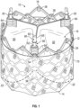
- FIG. 1 shows an exemplary prosthetic valve 10, according to one embodiment.
- the prosthetic valve 10 includes an annular stent or frame 12 having an inflow end 14 and an outflow end 16.
- the prosthetic valve 10 can also include a valvular structure 18 which is coupled to and supported inside of the frame 12.
- the valvular structure 18 is configured to regulate the flow of blood through the prosthetic valve 10 from the inflow end 14 to the outflow end 16.
- the valvular structure 18 can include, for example, a leaflet assembly comprising one or more leaflets 20 made of a flexible material.
- the leaflets 20 can be made from in whole or part, biological material, bio-compatible synthetic materials, or other such materials. Suitable biological material can include, for example, bovine pericardium (or pericardium from other sources).
- the leaflets 20 can be secured to one another at their adjacent sides to form commissures, each of which can be secured to a respective actuator 50 or the frame 102.
- the valvular structure 18 comprises three leaflets 20, which can be arranged to collapse in a tricuspid arrangement.
- Each leaflet 20 can have an inflow edge portion 22.
- the inflow edge portions 22 of the leaflets 20 can define an undulating, curved scallop shape that follows or tracks a plurality of interconnected strut segments of the frame 12 in a circumferential direction when the frame 12 is in the radially expanded configuration.
- the inflow edges of the leaflets can be referred to as a "scallop line.”
- the inflow edge portions 22 of the leaflets 20 can be sutured to adjacent struts of the frame generally along the scallop line. In other embodiments, the inflow edge portions 22 of the leaflets 20 can be sutured to an inner skirt, which in turn in sutured to adjacent struts of the frame.
- stresses on the leaflets 20 are reduced, which in turn improves durability of the valve 10.
- folds and ripples at the belly of each leaflet 20 (the central region of each leaflet), which can cause early calcification in those areas, can be eliminated or at least minimized.
- the scallop geometry also reduces the amount of tissue material used to form valvular structure 18, thereby allowing a smaller, more even crimped profile at the inflow end 14 of the valve 10.
- transcatheter prosthetic heart valves including the manner in which the valvular structure can be mounted to the frame of the prosthetic valve can be found, for example, in U.S. Patent Nos. 6,730,118 , 7,393,360 , 7,510,575 , 7,993,394 , and 8,252,202 , U.S. Publication No. 2018/0325665 and U.S. Patent Application No. 16/941,776, filed July 29, 2020 .
- the prosthetic valve 10 can be radially compressible and expandable between a radially compressed configuration and a radially expanded configuration.
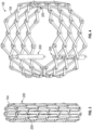
- FIGS. 2A-2B show the bare frame 12 of the prosthetic valve 10 (without the leaflets and other components) for purposes of illustrating expansion of the prosthetic valve 10 from the radially compressed configuration ( FIG. 2A ) to the radially expanded configuration ( FIG. 2B ).
- the frame 12 can include a plurality of interconnected lattice struts 24 arranged in a lattice-type pattern and forming a plurality of apices 34 at the outflow end 16 of the prosthetic valve 10.
- the struts 24 can also form similar apices 32 at the inflow end 14 of the prosthetic valve 10.
- FIG. 2B the struts 24 are shown as positioned diagonally, or offset at an angle relative to, and radially offset from, a longitudinal axis 26 of the prosthetic valve 10 when the prosthetic valve 10 is in the expanded configuration.
- the struts 24 can be offset by a different amount than depicted in FIG. 2B , or some or all of the struts 24 can be positioned parallel to the longitudinal axis 26 of the prosthetic valve 10.
- the struts 24 can comprise a set of inner struts 24a (extending from the lower left to the upper right of the frame in FIG. 2B ) and a set of outer struts 24b (extending from the upper left to the lower right of the frame in FIG. 2B ) connected to the inner struts 24a.
- the open lattice structure of the frame 12 can define a plurality of open frame cells 36 between the struts 24.
- the struts 24 can be pivotably coupled to one another at one or more pivot joints or pivot junctions 28 along the length of each strut.
- each of the struts 24 can be formed with apertures 30 at opposing ends of the strut and apertures spaced along the length of the strut.
- Respective hinges can be formed at the locations where struts 24 overlap each other via fasteners 38 ( FIG. 1 ), such as rivets or pins that extend through the apertures 30.
- the hinges can allow the struts 24 to pivot relative to one another as the frame 12 is radially expanded or compressed, such as during assembly, preparation, or implantation of the prosthetic valve 10.
- the frame struts and the components used to form the pivot joints of the frame 12 can be made of any of various suitable materials, such as stainless steel, a cobalt chromium alloy, or a nickel titanium alloy ("NiTi"), for example Nitinol.
- the frame 12 can be constructed by forming individual components (e.g., the struts and fasteners of the frame) and then mechanically assembling and connecting the individual components together. Further details regarding the construction of the frame and the prosthetic valve are described in U.S. Patent Nos. 10,603,165 and 10,806,573 , U.S. Publication Nos. 2018/0344456 and 2020/0188099 .
- the prosthetic valve 10 can be mechanically expanded from the radially contracted configuration to the radially expanded configuration.
- the prosthetic valve 10 can be radially expanded by maintaining the inflow end 14 of the frame 12 at a fixed position while applying a force in the axial direction against the outflow end 16 toward the inflow end 14.
- the prosthetic valve 10 can be expanded by applying an axial force against the inflow end 14 while maintaining the outflow end 16 at a fixed position, or by applying opposing axial forces to the inflow and outflow ends 14, 16, respectively.
- the prosthetic valve 10 can include one or more actuators 50 mounted to and equally spaced around the inner surface of the frame 12.
- Each of the actuators 50 can be configured to form a releasable connection with one or more respective actuators of a delivery apparatus.
- each of the actuators 50 can comprise a screw or threaded rod 52, a first anchor in the form of a cylinder or sleeve 54, and a second anchor in the form of a threaded nut 56.
- the rod 52 extends through the sleeve 54 and the nut 56.
- the sleeve 54 can be secured to the frame 12, such as with a fastener 38 that forms a hinge at the junction between two struts.
- Each actuator 50 is configured to increase the distance between the attachment locations of a respective sleeve 54 and nut 56, which causes the frame 12 to elongate axially and compress radially, and to decrease the distance between the attachment locations of a respective sleeve 54 and nut 56, which causes the frame 12 to foreshorten axially and expand radially.
- each rod 52 can have external threads that engage internal threads of the nut 56 such that rotation of the rod causes corresponding axial movement of the nut 56 toward or away from the sleeve 54 (depending on the direction of rotation of the rod 52). This causes the hinges supporting the sleeve 54 and the nut 56 to move closer towards each other to radially expand the frame or to move farther away from each other to radially compress the frame, depending on the direction of rotation of the rod 52.
- the actuators 50 can be reciprocating type actuators configured to apply axial directed forces to the frame to produce radial expansion and compression of the frame.
- the rod 52 of each actuator can be fixed axially relative to the sleeve 56 and slidable relative to the sleeve 54.
- moving the rod 52 distally relative to the sleeve 54 and/or moving the sleeve 54 proximally relative to the rod 52 radially compresses the frame.
- moving the rod 52 proximally relative to the sleeve 54 and/or moving the sleeve 54 distally relative to the rod 52 radially expands the frame.
- the prosthetic valve can also include one or more locking mechanisms that retain the frame in the expanded state.
- the locking mechanisms can be separate components that are mounted on the frame apart from the actuators, or they can be a sub-component of the actuators themselves.
- Each rod 52 can include an attachment member 58 along a proximal end portion of the rod 52 configured to form a releasable connection with a corresponding actuator of a delivery apparatus.
- the actuator(s) of the delivery apparatus can apply forces to the rods for radially compressing or expanding the prosthetic valve 10.
- the attachment member 58 in the illustrated configuration comprises a notch 60 and a projection 62 that can engage a corresponding projection of an actuator of the delivery apparatus.
- the prosthetic valve 10 includes three such actuators 50, although a greater or fewer number of actuators could be used in other embodiments.
- the leaflets 20 can have commissure attachments members 64 that wrap around the sleeves 54 of the actuators 50.
- Further details of the actuators, locking mechanisms and delivery apparatuses for actuating the actuators can be found in U.S. Patent No. 10,603,165 and U.S. Publication Nos. 2019/0060057 , and 2018/0325665 .
- Any of the actuators and locking mechanisms disclosed in the previously filed applications can be incorporated in any of the prosthetic valves disclosed herein.
- any of the delivery apparatuses disclosed in the previously filed applications can be used to deliver and implant any of the prosthetic valves discloses herein.
- the prosthetic valve 10 can include one or more skirts or sealing members.
- the prosthetic valve 10 can include an inner skirt (not shown) mounted on the inner surface of the frame.
- the inner skirt can function as a sealing member to prevent or decrease perivalvular leakage, to anchor the leaflets to the frame, and/or to protect the leaflets against damage caused by contact with the frame during crimping and during working cycles of the prosthetic valve.
- the prosthetic valve 10 can also include an outer skirt 70 mounted on the outer surface of the frame 12.
- the outer skirt 70 can function as a sealing member for the prosthetic valve by sealing against the tissue of the native valve annulus and helping to reduce paravalvular leakage past the prosthetic valve.
- the inner and outer skirts can be formed from any of various suitable biocompatible materials, including any of various synthetic materials, including fabrics (e.g., polyethylene terephthalate fabric) or natural tissue (e.g., pericardial tissue). Further details regarding the use of skirts or sealing members in prosthetic valve can be found, for example, in U.S. Patent No. 10,806,573 .
- FIGS. 3-4 show another embodiment of a prosthetic valve 100 comprising a frame 104 and expansion and locking mechanisms 200 (also referred to as "actuators").
- the prosthetic valve 100 can include leaflets 20 and other soft components, such as one or more skirts 70, which are removed for purposes of illustration.
- Expansion and locking mechanism 200 can be used to both radially expand and lock the prosthetic valve in a radially expanded state.
- three expansion and locking mechanisms 200 are attached to the frame 104 but in other example delivery assemblies, any number of expansion and locking mechanisms 200 can be used.
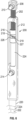
- FIG. 3 shows the expansion and locking mechanisms 200 attached to the frame 104 when the frame is in a radially collapsed configuration
- FIG. 4 shows expansion and locking mechanisms attached to the frame when the frame is in a radially expanded configuration.
- prosthetic valve 100 can, in certain embodiments, use other mechanisms for expansion and locking, such as linear actuators, alternate locking mechanisms, and alternate expansion and locking mechanisms. Further details regarding the use of linear actuators, locking mechanisms, and expansion and locking mechanisms in prosthetic valve can be found, for example, in U.S. Patent No. 10,603,165 .
- the expansion and locking mechanism 200 in the illustrated embodiment can include an actuator screw 202 (which functions as a linear actuator or a push-pull member in the illustrated embodiment) comprising a relatively long upper, or distal, portion 204 and a relatively shorter lower, or proximal, portion 206 at the proximal end of the screw 200, wherein the lower portion has a smaller diameter than the upper portion.
- Both the upper and lower portions 204, 206 of the screw 202 can have externally threaded surfaces.
- the actuator screw 200 can have a distal attachment piece 208 attached to its distal end having a radially extending distal valve connector 210.
- the distal attachment piece 208 can be fixed to the screw 202 (e.g., welded together or manufactured as one piece).
- the distal valve connector 210 can extend through an opening at or near the distal end of the frame 104 formed at a location on the frame where two or more struts intersect as shown in FIG. 5C .
- the distal valve connector 210 can be fixed to the frame 104 (e.g., welded). Due to the shape of the struts, the distal end of the frame 104 comprises an alternating series of distal junctions 150 and distal apices 152.
- the distal valve connectors 210 of the three expansion and locking mechanisms 200 are connected to the frame 104 through distal junctions 150.
- one or more distal valve connectors 210 can be connected to the frame 104 through distal apices 152.
- the distal valve connectors 210 can be connected to junctions closer to the proximal end of the frame 104.
- the expansion and locking mechanism 200 can further include a sleeve 212.
- the sleeve 212 can be positioned annularly around the distal portion 204 of the screw 202 and can contain axial openings at its proximal and distal ends through which the screw 202 can extend.
- the axial openings and the lumen in the sleeve 212 can have a diameter larger than the diameter of the distal portion 204 of the screw 202 such that the screw can move freely within the sleeve (the screw 202 can be moved proximally and distally relative to the sleeve 212). Because the actuator screw 202 can move freely within the sleeve, it can be used to radially expand and/or contract the frame 104 as disclosed in further detail below.
- the sleeve 212 can have a proximal valve connector 214 extending radially from its outer surface.
- the proximal valve connector 214 can be fixed to the sleeve 212 (e.g., welded).
- the proximal valve connector 214 can be axially spaced from the distal valve connector 210 such that the proximal valve connector can extend through an opening at or near the proximal end of the frame 104.
- the proximal end of the frame 104 comprises an alternating series of proximal junctions 160 and proximal apices 162.
- the proximal valve connectors 214 of the three expansion and locking mechanisms 200 are connected to the frame 104 through proximal junctions 160.
- one or more proximal valve connectors 214 can be connected to the frame 104 through proximal apices 162. In other embodiments, the proximal valve connectors 214 can be connected to junctions closer to the distal end of the frame 104.
- distal and proximal connectors 210, 214 need not be connected to opposite ends of the frame.
- the actuator 200 can be used to expand and compress the frame as long as the distal and proximal connectors are connected to respective junctions on the frame that are axially spaced from each other.
- a locking nut 216 can be positioned inside of the sleeve 212 and can have an internally threaded surface that can engage the externally threaded surface of the actuator screw 202.
- the locking nut 216 can have a notched portion 218 at its proximal end, the purpose of which is described below.
- the locking nut can be used to lock the frame 104 into a particularly radially expanded state, as discussed below.
- FIGS. 6 and 7 shows the expansion and locking mechanism 200 including components of a delivery apparatus not shown in FIGS. 5A-5C .
- the expansion and locking mechanism 200 can be releasably coupled to a support tube 220, an actuator member 222, and a locking tool 224.
- the proximal end of the support tube 220 can be connected to a handle or other control device (not shown) that a doctor or operator of the delivery assembly utilizes to operate the expansion and locking mechanism 200 as described herein.
- the proximal ends of the actuator member 222 and the locking tool 224 can be connected to the handle.
- the support tube 220 annularly surrounds a proximal portion of the locking tool 224 such that the locking tool extends through a lumen of the support tube.
- the support tube 220 and the sleeve are sized such that the distal end of the support tube abuts or engages the proximal end of the sleeve 212 such that the support tube is prevented from moving distally beyond the sleeve.
- the actuator member 222 extends through a lumen of the locking tool 224.
- the actuator member 222 can be, for example, a shaft, a rod, a cable, or wire.
- the distal end portion of the actuator member 222 can be releasably connected to the proximal end portion 206 of the actuator screw 202.
- the distal end portion of the actuator member 222 can have an internally threaded surface that can engage the external threads of the proximal end portion 206 of the actuator screw 202.
- the actuator member 222 can have external threads that engage an internally threaded portion of the screw 202.
- the distal portion of the locking tool 224 annularly surrounds the actuator screw 202 and extends through a lumen of the sleeve 212 and the proximal portion of the locking tool annularly surrounds the actuator member 222 and extends through a lumen of the support tube 220 to the handle of the delivery device.
- the locking tool 224 can have an internally threaded surface that can engage the externally threaded surface of the locking screw 202 such that clockwise or counter-clockwise rotation of the locking tool 224 causes the locking tool to advance distally or proximally along the screw, respectively.
- the distal end of the locking tool 224 can comprise a notched portion 226, as can best be seen in FIG. 6 .
- the notched portion 226 of the locking tool 224 can have an engagement surface 227 that is configured to engage a correspondingly shaped engagement surface 219 of the notched portion 218 of the locking nut 216 such that rotation of the locking tool (e.g., clockwise rotation) causes the nut 216 to rotate in the same direction (e.g., clockwise) and advance distally along the locking screw 202.
- the notched portions 218, 226 in the illustrated embodiment are configured such that rotation of the locking tool 224 in the opposite direction (e.g., counter-clockwise) allows the notched portion 226 of the tool 224 to disengage the notched portion 218 of the locking nut 216; that is, rotation of the locking tool in a direction that causes the locking tool to move proximally does not cause corresponding rotation of the nut.
- the distal end portion of the locking tool 224 can have various other configurations adapted to engage the nut 216 and produce rotation of the nut upon rotation of the locking tool for moving the nut distally, such as any of the tool configurations described herein.
- the distal end portion of the locking tool 224 can be adapted to produce rotation of the nut 216 in both directions so as move the nut distally and proximally along the locking screw 202.
- the actuator member 222 is screwed onto the proximal end portion 206 of the actuator screw 202 and the locking nut 216 is rotated such that it is positioned at the proximal end of the screw.
- the frame 104 can then be placed in a radially collapsed state and the delivery assembly can be inserted into a patient. Once the prosthetic valve is at a desired implantation site, the frame 104 can be radially expanded as described herein.
- the support tube 220 is held firmly against the sleeve 212.
- the actuator member 222 is then pulled in a proximal direction through the support tube, such as by pulling on the proximal end of the actuator member or actuating a control knob on the handle that produces proximal movement of the actuator member. Because the support tube 220 is being held against the sleeve 212, which is connected to a proximal end of the frame 104 by the proximal valve connector 214, the proximal end of the frame is prevented from moving relative to the support tube.
- movement of the actuator member 222 in a proximal direction causes movement of the actuator screw 202 in a proximal direction (because the actuator member is threaded onto the screw), thereby causing the frame 104 to foreshorten axially and expand radially.
- the frame 104 can be expanded by moving the support tube 220 distally while holding the actuator member 222 stationary or moving the support tube distally while moving the actuator member 222 proximally.
- the frame can be locked at this radially expanded size as described herein. Locking the frame can be achieved by rotating the locking tool 224 in a clockwise direction causing the notched portion 226 of the locking tool to engage the notched portion 218 of the locking nut 216, thereby advancing the locking nut distally along the actuator screw 202.
- the locking tool 224 can be so rotated until the locking nut 216 abuts an internal shoulder at the distal end of the sleeve 212 and the locking nut 216 cannot advance distally any further (see FIG. 6 ).
- the locking tool 224 can be rotated in a direction to move the locking tool proximally (e.g., in a counter-clockwise direction) to decouple the notched portion 226 from the notched portion 218 of the locking nut 216 and to unscrew the locking tool from the actuator screw 204.
- the actuator member 222 can be rotated in a direction to unscrew the actuator member from the lower portion 206 of the actuator screw 202 (e.g., the actuator member 222 can be configured to disengage from the actuator screw when rotated counter-clockwise).
- the locking tool 224 and the actuator member 222 are unscrewed from the actuator screw 204, they can be removed from the patient along with the support tube 220, leaving the actuator screw and the sleeve 212 connected to the frame 104, as shown in FIG. 5C , with the frame 104 locked in a particular radially-expanded state.
- the locking tool 224 can be formed without internal threads that engage the external threads of the actuator screw 202, which can allow the locking tool 224 to be slid distally and proximally through the sleeve 212 and along the actuator screw 202 to engage and disengage the nut 216.
- expansion and locking mechanisms can be used instead of the design previously described. Details on expansion and locking mechanisms can be found, for example, in U.S. Patent No. 10,603,165.
- FIGS. 8-10 illustrate an exemplary embodiment of a prosthetic heart valve 300 comprising a frame 302 and one or more expansion and locking mechanisms 310.
- the described embodiments refer to a mechanically expandable prosthetic valve having pivotably coupled struts, the expansion and locking mechanisms described herein can also be used with other mechanically expandable prosthetic valves, such as those described in U.S. Provisional Application No. 63/085,947 .
- the frame 302 comprises a plurality of pivotably connected struts 304 defining an inflow end 306 (which is the distal end of the frame in the delivery configuration for the illustrated embodiment) and an outflow end 308 (which is the proximal end of the frame in the delivery configuration for the illustrated embodiment).
- the struts 304 are pivotably connected to each other at a plurality of junctions that permit pivoting of the struts relative to each other when the frame 302 is radially compressed and expanded, as described above in connection with prosthetic valves 10 and 100.
- the prosthetic valve 300 can include a valvular structure (e.g., valvular structure 18) and inner and/or outer skirts, as previously described, although these components are omitted for purposes of illustration. While only a portion of the frame 302 is depicted in FIGS. 8-10 , it should be appreciated that frame 302 forms an annular structure similar to frame 12 of prosthetic valve 10.
- the one or more expansion and locking mechanisms 310 are used in lieu of or in addition to actuators 50 described above, and comprise a first or outer member 312, a second or inner member 314, and a third or locking member 316.
- the expansion and locking mechanisms 310 can be used to radially expand the frame 302 and to lock the frame in a radially expanded state, as described in more detail below.
- the frame 302 can comprise a plurality of inflow junctions or apices 318 at the inflow end portion 306 and a plurality of outflow junctions or apices 320 at the outflow end portion 308.
- Selected inflow apices 318 can comprise one or more flanges 322 configured to engage the locking member 316 of the expansion and locking mechanism 310 to lock the prosthetic valve 300 in the radially expanded configuration.
- the expansion and locking mechanisms 310 can be circumferentially aligned with the selected inflow apices 318 comprising flanges 322.
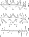
- FIGS. 8-10 illustrate a selected inflow apex 322 comprising a first, radially inner strut 304a and a second, radially outer strut 304b.
- First strut 304a includes first flange 322a and second strut 304b includes second flange 322b.
- first and second struts 304a, 304b pivot relative to one another to define a gap G between them, as shown in FIG. 9 .
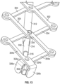
- Each flange 322a, 322b can comprise a respective axial portion 324a, 324b that extends axially past the junction of the first and second struts 304a, 304b, and a respective radial portion 326a, 326b ( FIG. 15 ) that extends radially inward toward a longitudinal axis of the prosthetic valve 300.
- the expansion and locking mechanisms 310 can be mounted on the outside of the frame 312 and the radial portions 326a, 326b can extend radially outward from the frame.
- the first axial portion 324a can have a length L 1 and the second axial portion 324b can have a length L 2 .
- the length L 2 can be greater than the length L 1 , or vice versa, such that when the frame 302 is in the radially compressed configuration (see e.g., FIGS. 14-15 ) the radial portions 326a, 326b can be circumferentially aligned with one another (meaning that their respective circumferential positions are aligned along a line that is parallel to a longitudinal axis of the frame).
- the differing lengths L 1 and L 2 of the axial portions 324a, 324b allow the flanges 322a, 322b to pivot relative to one another about inflow apex 318 without the radial portions 326a, 326b contacting or abutting one another.
- the first radial portion 326a can have a length L 3 and the second radial portion 326b can have a length L 4 .
- Length L 4 can be greater than length L 3 such that when the radial portions 326a, 326b are circumferentially aligned with one another both radial portions terminate at substantially the same radial location. In other words, neither radial portion extends past the other.
- the length L 3 can be greater than the length L 4 .
- FIGS. 8-10 show only a single expansion and locking mechanism 310 mounted to the frame 302, it should be appreciated that the prosthetic valve 300 can comprise any number of expansion and locking mechanisms 310.
- a prosthetic valve can comprise two expansion and locking mechanisms, or three expansion and locking mechanisms, or four expansion and locking mechanisms, etc.
- the expansion and locking mechanisms 310 can be placed at any position about the circumference of the frame 302.
- the expansion and locking mechanisms 310 can be equally spaced from one another about the circumference of the frame 302.
- each expansion and locking mechanism 310 includes a first, or outer member 312, a second or inner member 314, and a locking member 316.
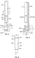
- the outer member 312 can comprise a first lumen or bore 328 ( FIG. 12 ) sized to receive at least a portion of the inner member 314, and the inner member 314 can comprise a second lumen or bore 330 ( FIG. 12 ) sized to receive at least a portion of the locking member 316.
- the outer member 312, inner member 314, and locking member 316 can each move axially relative to one another.
- a distal end portion 332 of the inner member 314 can be coupled to the frame 302 at a first location via a fastener 334 that is affixed to and extends radially from the distal end portion 332 of the inner member 314.
- the fastener can be, for example, a rivet or a pin.
- the fastener 334 can extend through corresponding apertures at a junction of two overlapping struts 304 of frame 302 and can serve as a pivot pin around which the two struts 304 can pivot relative to one another and the inner member 314.
- an end cap or nut can be disposed over an end portion of the fastener 334 to retain the fastener within the corresponding apertures.
- the outer member 312 can be coupled to the frame 302 at a second location, axially spaced from the first location.
- the inner member 314 is secured to the frame 302 near the distal or inflow end 306 of the frame and the outer member 312 is secured to the frame 302 closer to or at the proximal or outflow end 308 of the frame, such as via a fastener 336 ( FIG. 11 ), which can be, for example, a rivet or a pin.
- the fastener 336 is affixed to and extends radially from the outer member 312 through corresponding apertures at a junction of two overlapping struts 304 and can serve as a pivot pin around which the two struts 304 can pivot relative to each other and the outer member 312.
- a nut can be mounted on each fastener 336 to retain the fastener within the corresponding apertures.
- the expansion and locking mechanism 310 can be coupled to the frame 302 at any two axially spaced, circumferentially aligned locations on the frame.
- the inner member and/or outer member 314, 312 need not comprise fasteners 334, 336 and can be coupled to the frame 302 via other means of attachment such as welding, adhesives, etc.
- the inner member 314 can be axially movable relative to the outer member 312 in a proximal direction, as shown by arrow 338, and in a distal direction, as shown by arrow 340.
- arrow 338 a proximal direction
- distal direction a distal direction
- arrow 340 a distal direction
- moving the inner member 314 proximally toward the outflow end 308 of the frame, as shown by arrow 338, while holding the outer member 312 in a fixed position and/or moving the outer member 312 distally toward the inflow end 306 of the frame can cause the frame 302 to foreshorten axially and expand radially.
- moving the inner member 314 distally in the direction of arrow 338 and/or moving the outer member 312 proximally causes the frame 302 to elongate axially and compress radially.
- outer member 312 can further comprise a recess 342.
- the recess 342 can extend through a thickness of the outer member 312 and can extend to the distal edge 344 of the outer member.
- the recess 342 can be configured to limit the proximal advancement of the inner member 314 within the outer member 312.
- the inner member 314 can slide relative to the outer member 312 such that the fastener 334 of the inner member 314 can slide within the recess 342.
- the inner member 314 can continue moving relative to the outer member 312 until the fastener 334 abuts a proximal edge 346 of the recess 342, restraining further motion of the inner member 314 relative to the outer member 312.
- the locking member 316 can have a first end portion 348 and a second end portion 350.
- the first end portion 348 can have a circular shape in cross-section and can extend at least partially into the second bore 330 of the inner member 314.
- the second end portion 350 can comprise an engagement member 352 configured to engage one or more portions of the frame 302 to lock the frame 302 in the expanded configuration and prevent compression of the frame, as described in more detail below.
- the engagement member 352 is configured as a wedge having a base portion 354 and an apical portion 356.
- the base portion 354 can have a first width Wi that tapers to a second width W 2 at the apical portion 356.
- the base portion 354 can comprise a shoulder 358 sized to abut a distal edge 360 of the second member 314, thereby preventing movement of the locking member 316 relative to the second member 314 past a predetermined point.
- the engagement member 352 can have a first side wall 362 and a second side wall 364 inclined relative to one another at an angle ⁇ , also referred to as the "wedge angle.”
- the wedge angle ⁇ can be selected according to the following Equation 1.
- the wedge angle ⁇ can be between about 0 degrees and about 10 degrees.
- the wedge angle ⁇ can be between about 4 degrees and about 6 degrees.
- the wedge angle ⁇ can be determined using the coefficient of friction between metals.
- the static coefficient of wet friction for metals can be between about 0.1 to about 0.3. If the tangent of the wedge angle is less than the coefficient of friction, the locking member 316 will remain in the locked position under the radial forces applied by the native aortic annulus.
- the outer member 312, inner member 314, and locking member 316 can each have a substantially cylindrical configuration.
- This configuration can advantageously simplify manufacturing, for example, by allowing much simpler processing and machining procedures (such as Swiss-type and milling procedures) to be used.
- the telescoping movement of the members 312, 314, 316 relative to one another advantageously provides continuous valve expansion wherein the expansion and locking mechanism 310 can be easily maneuvered between the locked and unlocked configurations.
- the proximal end portion of each member 312, 314, 316 can comprise an engagement portion configured to releasably couple a corresponding actuator of a delivery apparatus, as described in more detail below.
- the proximal end portion 366 of the outer member 312 comprises an outer engagement portion configured as a threaded portion 368
- the proximal end portion 370 of the second member 314 comprises an engagement portion 372 including one or more cutouts
- a proximal end portion 374 of the locking member 316 can comprise an engagement portion configured as an inner bore including, for example, a threaded portion 376 ( FIG. 18 ).
- the expansion and locking mechanism 310 can be releasably coupled to a delivery apparatus, such as delivery apparatus 500 ( FIG. 22 ) comprising one or more actuator assemblies 508.
- a delivery apparatus such as delivery apparatus 500 ( FIG. 22 ) comprising one or more actuator assemblies 508.
- an actuator assembly 508 can couple a respective expansion and locking mechanism 310 in the following exemplary manner.
- the outer threaded portion 368 ( FIG. 25A ) of the outer member 312 can be configured to couple a correspondingly threaded portion 369 of a first actuator 367 of the delivery apparatus.
- a proximal end portion 370 ( FIG. 17 ) of the second member 314 can comprise an engagement portion 372 including one or more cutouts and configured to releasably couple a second actuator 371 extending coaxially through the first actuator 367.
- the second actuator 371 can comprise one or more flexible elongated elements 375 including protrusions 377 configured to releasably couple the engagement portion 372 of the second member 314.
- the elongated elements 375 can be disposed, for example, at the distal end of the second actuator 371.
- the elongated elements can be formed by, for example, laser cutting, and the protrusions 377 can have a shape corresponding to the shape of the cutouts.
- the elongated elements 375 can be configured to bias radially outward, for example, by shape setting the elongated elements 375.
- the second actuator 371 can comprise a cutout 365 configured to allow the elongated elements 375 to flex outward.
- the second actuator 371 can be positioned such that the protrusions 377 are disposed adjacent the cutouts of the engagement portion 372, as shown in FIG. 25C .
- the first actuator 367 is advanced (e.g., distally) over the second actuator to couple the outer member 312, the elongated elements 375 are radially compressed until they sit within the cutouts, as shown in FIG.
- the first actuator 367 can continue to be advanced until the threaded portion 369 of the first actuator 367 engages the threaded portion 368 of the outer member 312, as shown in FIG. 26 .
- a proximal end portion 374 of the locking member 316 can comprise an engagement portion configured as an inner bore including a threaded portion 376.
- a third actuator 373 of the delivery apparatus can extend coaxially through the first and second actuators 367, 371 and can have a correspondingly threaded portion 379 configured to releasably couple the threaded portion 376 of the locking member 316.
- the first, second, and third actuators 367, 371 and 373 can form an actuator assembly 508.
- Each actuator assembly 508 can be releasably coupled to and control operation of a respective expansion and locking mechanism 310.
- Each actuator assembly 508 can be coupled to a handle 504 of the delivery apparatus and the components of the actuator assembly (e.g., actuators 367, 371, 373) can be axially movable relative to one another to cause corresponding axial movement of the first, second, and locking members 312, 314, 316 relative to one another, as further described below.
- the engagement portions can have other configurations that permit the first, second, and locking members 312, 314, 316 to be releasably coupled to the delivery apparatus.
- the engagement portion of the locking member 316 can comprise a magnetic material and the third actuator can comprise a corresponding magnet that can extend into the engagement portion.
- a prosthetic valve 300 including one or more expansion and locking mechanisms 310 can be expanded in the following exemplary manner.
- the prosthetic valve 300 is placed in a radially compressed state and releasably coupled to a distal end portion of a delivery apparatus (such as delivery apparatus 500 shown in FIG. 22 ), as described above, and advanced through the vasculature of a patient to a selected implantation site (e.g., the native aortic annulus).
- the prosthetic valve 300 can then be deployed at the implantation site and can be expanded and locked in the expanded configuration using the expansion and locking mechanisms 310.
- the delivery apparatus can be uncoupled from the expansion and locking mechanisms 310 and removed from the patient's body.
- the physician can actuate the delivery apparatus, which can actuate the one or more expansion and locking mechanisms 310.
- the second member 314 can move proximally (as shown by arrow 338) and/or the first member 312 can move distally (as shown by arrow 340) to decrease the distance between the attachment locations, causing the frame 302 to foreshorten axially and expand radially until a selected diameter is achieved.
- the radially inner and radially outer struts 304a, 304b can pivot relative to one another, thereby pivoting the first and second flanges 322a, 322b relative to one another to define the gap G between them (see FIG. 9 ).
- the physician can use the delivery apparatus to advance the locking member 316 distally until the engagement member 352 is disposed within the gap G between the first and second flanges 322a, 322b, as shown in FIG. 10 .
- the engagement of the engagement member 352 with the first and second flanges 322a, 322b retains the frame 302 in a locked configuration, where the frame can be further radially expanded but cannot be radially collapsed.
- the engagement of the engagement member 352, with the flanges 322 permits pivoting movement of the struts 304 relative to each other in a first direction to expand the frame 302 and resists pivoting movement of the struts 304 relative to each other to resist radial compression of the frame 302 from forces exerted on the frame by the surrounding anatomy.
- the frictional engagement between the engagement member 352 and the flanges 322 prevents the engagement member 352 from being displaced relative to the flanges 322.
- the patient's native anatomy e.g., the native aortic annulus
- the frictional engagement of the engagement member 352 with the flanges 322 prevents such forces from displacing the engagement member and compressing the frame 302.
- the prosthetic valve can be unlocked by retracting the locking member 316 proximally until the engagement member 352 is no longer disposed between the first and second flanges 322a, 322b, allowing the struts 304 to pivot freely relative to one another in either direction.
- a proximally-directed force must be applied to the locking member 316 that is greater than the force of the frictional engagement between the flanges 322 and the engagement member 352.
- the expansion and locking mechanism 310 can comprise second member 400.
- Second member 400 can be similar to second member 314 except that second member 400 can be configured to bias the locking member 316 in a distal direction, as described in more detail below.
- the second member 400 can have a first end portion 402 including a fastener 404 similar to fastener 332 described above, a second end portion 406, and an inner lumen or bore 408.
- the second member 400 can comprise a biasing portion 410 disposed between the first and second end portions 402, 406.
- the biasing portion 410 can be movable between a compressed configuration and an extended configuration and can be configured to bias the second end portion 406 in a first direction, for example, toward the inflow end portion 306 of the prosthetic valve 300.
- the biasing portion 410 is configured as a spring 412 (such as a compression spring).
- the spring 412 can be formed integrally with the second member 400, for example, by laser cutting a central portion of the second member 400 into a helical shape.
- the spring 412 can be formed as a separate component and can be coupled to the first and second end portions 402, 406 of the second member 400.
- the biasing portion 410 can have any of various configurations.
- the biasing portion 410 can comprise a spring washer, a compressible polymeric sleeve, etc.
- the locking member 316 extends at least partially through the second member 400.
- the biasing portion 410 can be sized such that when the prosthetic valve 300 is in the compressed configuration, the biasing portion 410 is axially compressed or loaded. In the loaded state, a distal edge 414 of the second member 400 applies a proximally-directed force to the shoulder 358 of the locking member 316.
- the biasing portion 410 biases the locking member 316 distally toward the inflow end 306 such that the engagement member 352 abuts the radially extending portion 326a of the first flange 322a.
- the inner and outer struts 304a, 304b pivot relative to one another, thereby pivoting the flanges 322 relative to one another to define the gap G between them.
- the biasing portion 410 continues to bias the locking member 316, and therefore the engagement portion 352, distally against the first and/or second flanges 322a, 322b until the gap G is large enough to accommodate the engagement member 352, at which point the biasing portion 410 will bias the engagement member 352 into the gap G, as shown in FIG. 21 .
- the frictional engagement between the engagement member 352 and the flanges 322 prevents the engagement member 352 from being displaced relative to the flanges 322.
- the patient's native anatomy e.g., the native aortic annulus
- the frictional engagement of the engagement member 352 with the flanges 322 prevents such forces from displacing the engagement member and compressing the frame 302.
- the prosthetic valve can be unlocked by retracting the locking member 316 proximally until the engagement member 352 is no longer disposed between the first and second flanges 322a, 322b, thereby allowing the struts 304 to pivot freely relative to one another in either direction.
- a proximally-directed force must be applied to the locking member 316 that is greater than the force of the frictional engagement between the flanges 322 and the engagement member 352 and the force of the biasing portion 410.
- the biasing portion 410 can be sized such that when the prosthetic valve 300 is in the expanded configuration ( FIG. 21 ), the biasing portion 410 is in the uncompressed or unloaded configuration such that the biasing portion no longer applies a biasing force. In other embodiments, the biasing portion 410 can be sized such that when the prosthetic valve 300 is in the expanded configuration, the biasing portion 410 continues to apply a biasing force in the distal direction to help retain the engagement member 352 between the flanges 322.
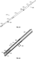
- FIG. 22 illustrates a delivery apparatus 500, according to one embodiment, adapted to deliver a prosthetic heart valve 502, such as the illustrated prosthetic heart valve 10, 100, or 300 described above.
- the prosthetic valve 502 can be releasably coupled to the delivery apparatus 500.
- the delivery apparatus 500 and other delivery apparatuses disclosed herein can be used to implant prosthetic devices other than prosthetic valves, such as stents or grafts.
- the delivery apparatus 500 in the illustrated embodiment generally includes a handle 504, a first elongated shaft 506 (which comprises an outer shaft in the illustrated embodiment) extending distally from the handle 504, at least one actuator assembly 508 extending distally through the outer shaft 506.
- the at least one actuator assembly 508 can be configured to radially expand and/or radially collapse the prosthetic valve 502 when actuated.
- each actuator 508 can be provided for each actuator (e.g., each expansion and locking mechanism) on the prosthetic valve.
- three actuator assemblies 508 can be provided for a prosthetic valve having three actuators. In other embodiments, a greater or fewer number of actuator assemblies can be present.
- a distal end portion 516 of the shaft 506 can be sized to house the prosthetic valve in its radially compressed, delivery state during delivery of the prosthetic valve through the patient's vasculature. In this manner, the distal end portion 516 functions as a delivery sheath or capsule for the prosthetic valve during delivery,
- each actuator assembly 508 can be releasably coupled to the prosthetic valve 502.
- each actuator assembly 508 can be coupled to a respective actuator (e.g., expansion and locking mechanism 310) of the prosthetic valve 502.
- Each actuator assembly 508 can comprise a first actuator (e.g., first actuator 367, which can be a support tube), a second actuator (e.g., second actuator 371), and a third actuator (e.g., third actuator 373, which can be a locking tool for operating locking member 316).
- the actuator assembly can transmit pushing and/or pulling forces to portions of the prosthetic valve to radially expand and collapse the prosthetic valve as previously described.
- the actuator assemblies 508 can be at least partially disposed radially within, and extend axially through, one or more lumens of the outer shaft 506.
- the actuator assemblies 508 can extend through a central lumen of the shaft 506 or through separate respective lumens formed in the shaft 506.
- the handle 504 of the delivery apparatus 500 can include one or more control mechanisms (e.g., knobs or other actuating mechanisms) for controlling different components of the delivery apparatus 500 in order to expand and/or deploy the prosthetic valve 10.
- control mechanisms e.g., knobs or other actuating mechanisms
- the handle 504 comprises first, second, third and fourth knobs 510, 512, 514, and 515.
- the first knob 510 can be a rotatable knob configured to produce axial movement of the outer shaft 506 relative to the prosthetic valve 502 in the distal and/or proximal directions in order to deploy the prosthetic valve from the delivery sheath 516 once the prosthetic valve has been advanced to a location at or adjacent the desired implantation location with the patient's body.
- rotation of the first knob 510 in a first direction e.g., clockwise
- rotation of the first knob 510 in a second direction e.g., counter-clockwise
- the first knob 510 can be actuated by sliding or moving the knob 510 axially, such as pulling and/or pushing the knob. In other embodiments, actuation of the first knob 510 (rotation or sliding movement of the knob 510) can produce axial movement of the actuator assemblies 508 (and therefore the prosthetic valve 502) relative to the delivery sheath 516 to advance the prosthetic valve distally from the sheath 516.
- the second knob 512 can be a rotatable knob configured to produce radial expansion and/or contraction of the prosthetic valve 502.
- rotation of the second knob 512 can move the first actuator (e.g., actuator 367) and the second actuator (e.g., actuator 371) relative to one another (for example, to cause corresponding movement of the outer and inner members 312, 314 relative to one another).
- Rotation of the second knob 512 in a first direction e.g., clockwise
- rotation of the second knob 512 in a second direction e.g., counter-clockwise
- the second knob 512 can be actuated by sliding or moving the knob 512 axially, such as pulling and/or pushing the knob.
- the first and second actuators can each be coupled to a respective knob such that they can be actuated independently from one another.
- the third knob 514 can be a rotatable knob configured to retain the prosthetic heart valve 502 in its expanded configuration.
- the third knob 514 can be operatively connected to a third actuator (e.g., third actuator 373) that can be releasably coupled to a locking member (e.g., locking member 316).
- Rotation of the third knob in a first direction can advance the third actuator distally to, for example, advance the engagement member 352 of locking member 316 such that it engages the flanges 322 to resist radial compression of the frame of the prosthetic valve, as described above.
- Rotation of the knob 514 in the opposite direction can retract the third actuator proximally to unlock the frame and allow for repositioning or recapture and removal.
- the third knob 514 can be actuated by sliding or moving the third knob 514 axially, such as pulling and/or pushing the knob.
- the handle 504 can include a fourth knob 515 (e.g., a rotatable knob) operatively connected to a proximal end portion of one or more of the actuators 367, 371, 373.
- the fourth knob 515 can be configured to, upon rotation of the knob, to decouple each of the one or more actuators from, for example, a respective component of the expansion and locking mechanism.
- the fourth knob 515 can be operable to rotate the first actuator 367 in a direction that causes a threaded distal end portion of the first actuator to decouple from the threaded portion 368 of the outer member 312 of the expansion and locking mechanism 310.
- the fourth knob 515 (or an additional knob) can be operable to rotate the third actuator 373 in a direction that causes a threaded distal end portion of the third actuator to decouple from the threaded portion 376 of the locking member 316 of the expansion and locking mechanism 310.
- the disclosed embodiments can be adapted to deliver and implant prosthetic devices in any of the native annuluses of the heart (e.g., the pulmonary, mitral, and tricuspid annuluses), and can be used with any of various delivery approaches (e.g., retrograde, antegrade, transseptal, transventricular, transatrial, etc.).
- native annuluses of the heart e.g., the pulmonary, mitral, and tricuspid annuluses
- various delivery approaches e.g., retrograde, antegrade, transseptal, transventricular, transatrial, etc.
- expansion and locking mechanisms 310 as shown in FIG. 11 or FIG. 20 can be used in combination with prosthetic valve 100 or with prosthetic valve 10.
- proximal refers to a position, direction, or portion of a device that is closer to the user and further away from the implantation site.
- distal refers to a position, direction, or portion of a device that is further away from the user and closer to the implantation site.
- proximal motion of a device is motion of the device away from the implantation site and toward the user (e.g., out of the patient's body)
- distal motion of the device is motion of the device away from the user and toward the implantation site (e.g., into the patient's body).
Landscapes
- Health & Medical Sciences (AREA)
- Cardiology (AREA)
- Engineering & Computer Science (AREA)
- Biomedical Technology (AREA)
- Heart & Thoracic Surgery (AREA)
- Transplantation (AREA)
- Oral & Maxillofacial Surgery (AREA)
- Vascular Medicine (AREA)
- Life Sciences & Earth Sciences (AREA)
- Animal Behavior & Ethology (AREA)
- General Health & Medical Sciences (AREA)
- Public Health (AREA)
- Veterinary Medicine (AREA)
- Mechanical Engineering (AREA)
- Prostheses (AREA)
Claims (15)
- Dispositif prothétique implantable, comprenant :un cadre (12, 302) mobile entre une configuration radialement comprimée et une radialement agrandie, le cadre (12, 302) comprenant une partie d'extrémité d'écoulement entrant (14) et une partie d'extrémité d'écoulement sortant (16), le cadre (12, 302) comprenant une pluralité d'entretoises (304) ;au moins un mécanisme d'agrandissement et de verrouillage (310) comprenant :un premier organe (312) couplé au cadre à un premier emplacement,un deuxième organe (314) couplé au cadre (12, 302) à un second emplacement espacé du premier emplacement, le deuxième organe (314) s'étendant au moins partiellement dans le premier organe (312),un troisième organe (316) ayant une première partie d'extrémité (348) et une seconde partie d'extrémité (350), la première partie d'extrémité (348) s'étendant au moins partiellement dans le premier organe (312) et la seconde partie d'extrémité (350) comprenant une partie d'entrée en prise (352) ;dans lequel la pluralité d'entretoises (304) inclut une première entretoise (304a) et une seconde entretoise (304b) couplées de façon pivotante l'une à l'autre pour former un sommet, la première entretoise (304a) comprenant une première aile (322a) et la seconde entretoise comprenant une seconde aile (322b) ; etdans lequel, lorsque le cadre (12, 302) est dans la configuration agrandie, l'avance du troisième organe (316) dans une direction distale positionne la partie d'entrée en prise (352) entre les première et seconde ailes (322a, 322b) de manière telle que les première et seconde ailes (322a, 322b) entrent en prise avec l'organe d'entrée en prise (352) pour résister au pivotement des première et seconde entretoises (304a, 304b) l'une relativement à l'autre dans une première direction pour résister à la compression radiale du cadre (12, 302).
- Dispositif implantable de la revendication 1, dans lequel les premier, deuxième, et troisième organes (312, 314, 316) sont axialement mobiles les uns relativement aux autres.
- Dispositif implantable de l'une quelconque des revendications précédentes 1 et 2, dans lequel les première et seconde entretoises (304a, 304b) sont couplées de façon pivotante, à un sommet positionné au niveau de la partie d'extrémité d'écoulement entrant (306) du cadre (302).
- Dispositif implantable de quelconques des revendications précédentes 1 à 3, dans lequel les première et seconde ailes (322a, 322b) s'étendent radialement vers l'intérieur vers un axe longitudinal du cadre (302).
- Dispositif implantable de quelconques des revendications précédentes 1 à 4, dans lequel l'agrandissement du dispositif prothétique amène les première et seconde ailes (322a, 322b) à pivoter en éloignement l'une de l'autre pour définir un espace entre elles.
- Dispositif implantable de quelconques des revendications précédentes 1 à 5, dans lequel la partie d'entrée en prise (352) comprend une partie de base (354) et une partie de sommet (356), et dans lequel une épaisseur de la partie d'entrée en prise (352) s'effile depuis une première épaisseur au niveau de la partie de base (354) jusqu'à une seconde épaisseur au niveau de la partie de sommet (356), la première épaisseur étant supérieure à la seconde épaisseur.
- Dispositif implantable de quelconques des revendications précédentes 1 à 6, dans lequel la partie d'entrée en prise (352) comprend un épaulement (358) configuré pour sélectivement venir en butée contre une partie de bord distal (360) du deuxième organe (314) pour empêcher le mouvement du troisième organe (316) dans une direction proximale au-delà d'un point prédéterminé.
- Dispositif implantable de quelconques des revendications précédentes 1 à 7, dans lequel le premier organe (312) comprend un évidement (342) s'étendant proximalement depuis un bord distal (344) du premier organe (312),
optionnellement dans lequel le deuxième organe (314) comprend une pièce de fixation (334) s'étendant depuis une surface du deuxième organe (314), et dans lequel la pièce de fixation (334) est configurée pour sélectivement venir en butée contre un bord proximal (346) de l'évidement (342) pour résister au mouvement du deuxième organe (314) dans une direction proximale. - Dispositif implantable de quelconques des revendications précédentes 1 à 8, dans lequel le deuxième organe (314, 400) comprend un organe de sollicitation (410) mobile entre une position comprimée et une position étendue, et dans lequel le mouvement de l'organe de sollicitation (410) depuis la position comprimée jusqu'à la position étendue fait avancer le troisième organe (316) distalement.
- Dispositif implantable de quelconques des revendications précédentes 1 à 9, dans lequel la première aile (322a) comprend une première partie axiale (324a) ayant une première longueur, dans lequel la seconde aile (322b) comprend une second partie axiale (324b) ayant une seconde longueur, et dans lequel la seconde longueur est supérieure à la première longueur, optionnellement ou autrement dans lequel la première aile (322a) comprend une première partie radiale (326a) ayant une première longueur, dans lequel la seconde aile (322b) comprend une seconde partie radiale (326b) ayant une seconde longueur, et dans lequel la seconde longueur est supérieure à la première longueur.
- Ensemble, comprenant :le dispositif prothétique implantable de quelconques des revendications précédentes 1 à 10 ; etun appareil de pose (500) comprenantune poignée (504),un premier organe d'actionnement (367) s'étendant depuis la poignée (504) et couplé de façon libérable au premier organe (312), le premier organe d'actionnement (367) étant configuré pour appliquer une force en direction distale sur le premier organe (312),un deuxième organe d'actionnement (371) s'étendant depuis la poignée (504) et couplé de façon libérable au deuxième organe (314), le deuxième organe d'actionnement (371) étant configuré pour appliquer une force en direction proximale sur le deuxième organe (314),un troisième organe d'actionnement (373) s'étendant depuis la poignée (504) et couplé de façon libérable au troisième organe (316),dans lequel la valve cardiaque prothétique est radialement agrandissable depuis la configuration radialement comprimée jusqu'à la configuration radialement agrandie lors de l'application d'au moins une de la force en direction distale et de la force en direction proximale sur la valve cardiaque prothétique par l'intermédiaire des premier et deuxième organes d'actionnement (367, 371), respectivement ; etdans lequel, lorsque la valve cardiaque prothétique est dans la configuration radialement agrandie, la partie d'entrée en prise (352) du troisième organe (316) entre sélectivement en prise avec les première et seconde ailes (322a, 322b) pour empêcher la compression du cadre (12, 302).
- Ensemble de la revendication 11, dans lequel l'agrandissement de la valve prothétique amène les première et seconde ailes (322a, 322b) à pivoter en éloignement l'une de l'autre pour définir un espace entre elles, et
dans lequel :a) le troisième organe d'actionnement (373) est configuré pour appliquer une force en direction distale sur le troisième organe (316) pour faire avancer la partie d'entrée en prise (352) dans l'espace ; oub) le troisième organe (316) comprend une partie de sollicitation (410) mobile entre une configuration comprimée et une configuration étendue, et dans lequel le mouvement de la partie de sollicitation (410) depuis la configuration comprimée jusqu'à la configuration étendue fait avancer la partie d'entrée en prise (352) dans l'espace. - Ensemble de quelconques des revendications précédentes 11 et 12, dans lequel une partie d'extrémité d'écoulement sortant (366) du premier organe (312) comprend une partie d'entrée en prise filetée (368) configurée pour se coupler de façon libérable à une partie filetée correspondante (369) du premier organe d'actionnement (367).
- Ensemble de quelconques des revendications précédentes 11 à 13, dans lequel une partie d'extrémité d'écoulement sortant (370) du deuxième organe (314) comprend une ou plusieurs découpes (372) configurées pour se coupler de façon libérable au deuxième organe d'actionnement (371),
optionnellement dans lequel le deuxième organe d'actionnement (371) comprend un ou plusieurs éléments allongés flexibles (375) chacun ayant une forme (377) correspondant à une forme d'une découpe respective (372), optionnellement en outre dans lequel les éléments allongés flexibles (375) sont configurés pour effectuer une sollicitation radialement vers l'extérieur. - Ensemble de quelconques des revendications précédentes 11 à 14, dans lequel une partie d'extrémité d'écoulement sortant (374) du troisième organe (316) comprend un alésage intérieur ayant une partie d'entrée en prise filetée (376) configurée pour se coupler de façon libérable au troisième organe d'actionnement (373).
Priority Applications (1)
| Application Number | Priority Date | Filing Date | Title |
|---|---|---|---|
| EP24202596.3A EP4461267A3 (fr) | 2020-01-14 | 2021-01-08 | Mécanisme de détente et de verrouillage pour soupapes mécaniquement expansibles |
Applications Claiming Priority (2)
| Application Number | Priority Date | Filing Date | Title |
|---|---|---|---|
| US202062961043P | 2020-01-14 | 2020-01-14 | |
| PCT/US2021/012615 WO2021146101A1 (fr) | 2020-01-14 | 2021-01-08 | Mécanisme d'extension et de verrouillage pour vannes mécaniquement extensibles |
Related Child Applications (1)
| Application Number | Title | Priority Date | Filing Date |
|---|---|---|---|
| EP24202596.3A Division EP4461267A3 (fr) | 2020-01-14 | 2021-01-08 | Mécanisme de détente et de verrouillage pour soupapes mécaniquement expansibles |
Publications (2)
| Publication Number | Publication Date |
|---|---|
| EP4061284A1 EP4061284A1 (fr) | 2022-09-28 |
| EP4061284B1 true EP4061284B1 (fr) | 2024-10-02 |
Family
ID=74505352
Family Applications (2)
| Application Number | Title | Priority Date | Filing Date |
|---|---|---|---|
| EP21703109.5A Active EP4061284B1 (fr) | 2020-01-14 | 2021-01-08 | Mécanisme d'extension et de verrouillage pour vannes mécaniquement extensibles |
| EP24202596.3A Pending EP4461267A3 (fr) | 2020-01-14 | 2021-01-08 | Mécanisme de détente et de verrouillage pour soupapes mécaniquement expansibles |
Family Applications After (1)
| Application Number | Title | Priority Date | Filing Date |
|---|---|---|---|
| EP24202596.3A Pending EP4461267A3 (fr) | 2020-01-14 | 2021-01-08 | Mécanisme de détente et de verrouillage pour soupapes mécaniquement expansibles |
Country Status (4)
| Country | Link |
|---|---|
| US (1) | US20220338978A1 (fr) |
| EP (2) | EP4061284B1 (fr) |
| CN (1) | CN115151221A (fr) |
| WO (1) | WO2021146101A1 (fr) |
Families Citing this family (18)
| Publication number | Priority date | Publication date | Assignee | Title |
|---|---|---|---|---|
| US12186187B2 (en) | 2018-09-20 | 2025-01-07 | Vdyne, Inc. | Transcatheter deliverable prosthetic heart valves and methods of delivery |
| US12310850B2 (en) | 2018-09-20 | 2025-05-27 | Vdyne, Inc. | Transcatheter deliverable prosthetic heart valves and methods of delivery |
| US11253359B2 (en) | 2018-12-20 | 2022-02-22 | Vdyne, Inc. | Proximal tab for side-delivered transcatheter heart valves and methods of delivery |
| WO2020146842A1 (fr) | 2019-01-10 | 2020-07-16 | Vdyne, Llc | Crochet d'ancrage pour prothèse de valvule cardiaque transcathéter à distribution latérale |
| US11273032B2 (en) | 2019-01-26 | 2022-03-15 | Vdyne, Inc. | Collapsible inner flow control component for side-deliverable transcatheter heart valve prosthesis |
| EP4729034A2 (fr) | 2019-03-05 | 2026-04-22 | VDyne, Inc. | Dispositifs de commande de régurgitation tricuspide pour prothèse de valvule cardiaque par transcathéter orthogonal |
| US11173027B2 (en) | 2019-03-14 | 2021-11-16 | Vdyne, Inc. | Side-deliverable transcatheter prosthetic valves and methods for delivering and anchoring the same |
| AU2020267390B2 (en) | 2019-05-04 | 2025-12-04 | Vdyne, Inc. | Cinch device and method for deployment of a side-delivered prosthetic heart valve in a native annulus |
| EP4185244B1 (fr) | 2020-07-23 | 2025-01-29 | St. Jude Medical, Cardiology Division, Inc. | Valve cardiaque extensible à profil bas |
| WO2022159431A1 (fr) | 2021-01-20 | 2022-07-28 | Edwards Lifesciences Corporation | Dispositif d'amarrage bi-caval extensible mécaniquement |
| WO2023086470A1 (fr) * | 2021-11-10 | 2023-05-19 | Edwards Lifesciences Corporation | Dispositif prothétique expansible radialement |
| WO2023086318A1 (fr) * | 2021-11-11 | 2023-05-19 | Edwards Lifesciences Corporation | Couvercle pour mécanisme d'extension de valvule prothétique |
| EP4478991B1 (fr) * | 2022-02-15 | 2025-12-03 | Edwards Lifesciences Corporation | Mécanisme de verrouillage pour une valvule prothétique mécaniquement extensible |
| EP4493120A1 (fr) * | 2022-03-14 | 2025-01-22 | Edwards Lifesciences Corporation | Appareil de pose pour une valvule cardiaque prothétique à expansion mécanique |
| EP4498993A1 (fr) * | 2022-03-30 | 2025-02-05 | Edwards Lifesciences Corporation | Appareil de distribution de valvule mécaniquement expansible |
| EP4572712A1 (fr) * | 2022-08-19 | 2025-06-25 | Edwards Lifesciences Corporation | Appareil de pose pour une valvule cardiaque prothétique à expansion mécanique |
| EP4601585A1 (fr) * | 2022-10-14 | 2025-08-20 | Vdyne, Inc. | Dispositifs et procédés de pose d'une valve cardiaque prothétique à l'aide d'un support supra-annulaire |
| JP2025540697A (ja) * | 2022-11-23 | 2025-12-16 | ボストン サイエンティフィック サイムド,インコーポレイテッド | 心臓弁取付機構 |
Family Cites Families (13)
| Publication number | Priority date | Publication date | Assignee | Title |
|---|---|---|---|---|
| US6893460B2 (en) | 2001-10-11 | 2005-05-17 | Percutaneous Valve Technologies Inc. | Implantable prosthetic valve |
| US7445631B2 (en) * | 2003-12-23 | 2008-11-04 | Sadra Medical, Inc. | Methods and apparatus for endovascularly replacing a patient's heart valve |
| KR101454052B1 (ko) | 2007-05-17 | 2014-10-27 | 디아이씨 가부시끼가이샤 | 네마틱 액정 조성물 및 쌍안정성 네마틱 액정 디스플레이 |
| US9566178B2 (en) * | 2010-06-24 | 2017-02-14 | Edwards Lifesciences Cardiaq Llc | Actively controllable stent, stent graft, heart valve and method of controlling same |
| HUE047762T2 (hu) | 2008-06-06 | 2020-05-28 | Edwards Lifesciences Corp | Kis profilú transzkatéteres szívbillentyû |
| EP2438872B1 (fr) * | 2010-10-08 | 2020-11-04 | Biotronik AG | Implant médical, notamment stent, pour l'implantation dans un corps animal et/ou humain |
| CN111419472B (zh) * | 2013-11-11 | 2023-01-10 | 爱德华兹生命科学卡迪尔克有限责任公司 | 用于制造支架框架的系统和方法 |
| WO2017087424A1 (fr) * | 2015-11-17 | 2017-05-26 | Millipede, Inc. | Dispositif implantable et système de mise en place pour remodeler un anneau de valve cardiaque |
| US10603165B2 (en) | 2016-12-06 | 2020-03-31 | Edwards Lifesciences Corporation | Mechanically expanding heart valve and delivery apparatus therefor |
| US11135056B2 (en) | 2017-05-15 | 2021-10-05 | Edwards Lifesciences Corporation | Devices and methods of commissure formation for prosthetic heart valve |
| US10869759B2 (en) | 2017-06-05 | 2020-12-22 | Edwards Lifesciences Corporation | Mechanically expandable heart valve |
| US10806573B2 (en) | 2017-08-22 | 2020-10-20 | Edwards Lifesciences Corporation | Gear drive mechanism for heart valve delivery apparatus |
| AU2019361110A1 (en) | 2018-10-19 | 2021-05-13 | Edwards Lifesciences Corporation | Prosthetic heart valve having non-cylindrical frame |
-
2021
- 2021-01-08 CN CN202180016350.5A patent/CN115151221A/zh active Pending
- 2021-01-08 WO PCT/US2021/012615 patent/WO2021146101A1/fr not_active Ceased
- 2021-01-08 EP EP21703109.5A patent/EP4061284B1/fr active Active
- 2021-01-08 EP EP24202596.3A patent/EP4461267A3/fr active Pending
-
2022
- 2022-07-08 US US17/861,024 patent/US20220338978A1/en active Pending
Also Published As
| Publication number | Publication date |
|---|---|
| EP4461267A3 (fr) | 2025-02-19 |
| CN115151221A (zh) | 2022-10-04 |
| US20220338978A1 (en) | 2022-10-27 |
| EP4061284A1 (fr) | 2022-09-28 |
| EP4461267A2 (fr) | 2024-11-13 |
| WO2021146101A1 (fr) | 2021-07-22 |
Similar Documents
| Publication | Publication Date | Title |
|---|---|---|
| US20220338978A1 (en) | Expansion and locking mechanism for mechanically expandable valves | |
| US20230263630A1 (en) | Delivery apparatus for prosthetic implants | |
| US20230225863A1 (en) | Delivery apparatus for mechanically expandable valve | |
| US20250000644A1 (en) | Locking mechanism for a mechanically expandable prosthetic valve | |
| US20220160497A1 (en) | Prosthetic heart valve having at least two types of struts | |
| US20220387175A1 (en) | Prosthetic heart valve | |
| US20220280295A1 (en) | Prosthetic heart valve having non-linear struts | |
| EP4498993A1 (fr) | Appareil de distribution de valvule mécaniquement expansible | |
| US20240091004A1 (en) | Hybrid frame for prosthetic heart valve | |
| US20230355387A1 (en) | Mechanically expandable bi-caval docking device | |
| US20230190462A1 (en) | Hybrid frame for prosthetic heart valve | |
| US12611301B2 (en) | Commissure locking member | |
| US20240285404A1 (en) | Cover for prosthetic valve expansion mechanism | |
| US20230051890A1 (en) | Leaflet attachment in prosthetic heart valves using buckle commissure clamps | |
| WO2023183270A1 (fr) | Valvule cardiaque prothétique à expansion mécanique |
Legal Events
| Date | Code | Title | Description |
|---|---|---|---|
| STAA | Information on the status of an ep patent application or granted ep patent |
Free format text: STATUS: UNKNOWN |
|
| STAA | Information on the status of an ep patent application or granted ep patent |
Free format text: STATUS: THE INTERNATIONAL PUBLICATION HAS BEEN MADE |
|
| PUAI | Public reference made under article 153(3) epc to a published international application that has entered the european phase |
Free format text: ORIGINAL CODE: 0009012 |
|
| STAA | Information on the status of an ep patent application or granted ep patent |
Free format text: STATUS: REQUEST FOR EXAMINATION WAS MADE |
|
| 17P | Request for examination filed |
Effective date: 20220623 |
|
| AK | Designated contracting states |
Kind code of ref document: A1 Designated state(s): AL AT BE BG CH CY CZ DE DK EE ES FI FR GB GR HR HU IE IS IT LI LT LU LV MC MK MT NL NO PL PT RO RS SE SI SK SM TR |
|
| DAV | Request for validation of the european patent (deleted) | ||
| DAX | Request for extension of the european patent (deleted) | ||
| STAA | Information on the status of an ep patent application or granted ep patent |
Free format text: STATUS: EXAMINATION IS IN PROGRESS |
|
| 17Q | First examination report despatched |
Effective date: 20230522 |
|
| P01 | Opt-out of the competence of the unified patent court (upc) registered |
Effective date: 20230529 |
|
| REG | Reference to a national code |
Free format text: PREVIOUS MAIN CLASS: A61F0002240000 Ref country code: DE Ref legal event code: R079 Ref document number: 602021019576 Country of ref document: DE Free format text: PREVIOUS MAIN CLASS: A61F0002240000 Ipc: A61F0002966000 |
|
| GRAP | Despatch of communication of intention to grant a patent |
Free format text: ORIGINAL CODE: EPIDOSNIGR1 |
|
| STAA | Information on the status of an ep patent application or granted ep patent |
Free format text: STATUS: GRANT OF PATENT IS INTENDED |
|
| RIC1 | Information provided on ipc code assigned before grant |
Ipc: A61F 2/24 20060101ALI20240202BHEP Ipc: A61F 2/966 20130101AFI20240202BHEP |
|
| INTG | Intention to grant announced |
Effective date: 20240221 |
|
| GRAJ | Information related to disapproval of communication of intention to grant by the applicant or resumption of examination proceedings by the epo deleted |
Free format text: ORIGINAL CODE: EPIDOSDIGR1 |
|
| STAA | Information on the status of an ep patent application or granted ep patent |
Free format text: STATUS: EXAMINATION IS IN PROGRESS |
|
| GRAP | Despatch of communication of intention to grant a patent |
Free format text: ORIGINAL CODE: EPIDOSNIGR1 |
|
| STAA | Information on the status of an ep patent application or granted ep patent |
Free format text: STATUS: GRANT OF PATENT IS INTENDED |
|
| INTC | Intention to grant announced (deleted) | ||
| INTG | Intention to grant announced |
Effective date: 20240424 |
|
| GRAS | Grant fee paid |
Free format text: ORIGINAL CODE: EPIDOSNIGR3 |
|
| GRAA | (expected) grant |
Free format text: ORIGINAL CODE: 0009210 |
|
| STAA | Information on the status of an ep patent application or granted ep patent |
Free format text: STATUS: THE PATENT HAS BEEN GRANTED |
|
| AK | Designated contracting states |
Kind code of ref document: B1 Designated state(s): AL AT BE BG CH CY CZ DE DK EE ES FI FR GB GR HR HU IE IS IT LI LT LU LV MC MK MT NL NO PL PT RO RS SE SI SK SM TR |
|
| REG | Reference to a national code |
Ref country code: GB Ref legal event code: FG4D |
|
| REG | Reference to a national code |
Ref country code: CH Ref legal event code: EP |
|
| REG | Reference to a national code |
Ref country code: DE Ref legal event code: R096 Ref document number: 602021019576 Country of ref document: DE |
|
| REG | Reference to a national code |
Ref country code: IE Ref legal event code: FG4D |
|
| REG | Reference to a national code |
Ref country code: LT Ref legal event code: MG9D |
|
| REG | Reference to a national code |
Ref country code: NL Ref legal event code: MP Effective date: 20241002 |
|
| REG | Reference to a national code |
Ref country code: AT Ref legal event code: MK05 Ref document number: 1727949 Country of ref document: AT Kind code of ref document: T Effective date: 20241002 |
|
| PG25 | Lapsed in a contracting state [announced via postgrant information from national office to epo] |
Ref country code: NL Free format text: LAPSE BECAUSE OF FAILURE TO SUBMIT A TRANSLATION OF THE DESCRIPTION OR TO PAY THE FEE WITHIN THE PRESCRIBED TIME-LIMIT Effective date: 20241002 |
|
| PG25 | Lapsed in a contracting state [announced via postgrant information from national office to epo] |
Ref country code: NL Free format text: LAPSE BECAUSE OF FAILURE TO SUBMIT A TRANSLATION OF THE DESCRIPTION OR TO PAY THE FEE WITHIN THE PRESCRIBED TIME-LIMIT Effective date: 20241002 |
|
| PG25 | Lapsed in a contracting state [announced via postgrant information from national office to epo] |
Ref country code: IS Free format text: LAPSE BECAUSE OF FAILURE TO SUBMIT A TRANSLATION OF THE DESCRIPTION OR TO PAY THE FEE WITHIN THE PRESCRIBED TIME-LIMIT Effective date: 20250202 Ref country code: PT Free format text: LAPSE BECAUSE OF FAILURE TO SUBMIT A TRANSLATION OF THE DESCRIPTION OR TO PAY THE FEE WITHIN THE PRESCRIBED TIME-LIMIT Effective date: 20250203 Ref country code: HR Free format text: LAPSE BECAUSE OF FAILURE TO SUBMIT A TRANSLATION OF THE DESCRIPTION OR TO PAY THE FEE WITHIN THE PRESCRIBED TIME-LIMIT Effective date: 20241002 |
|
| PG25 | Lapsed in a contracting state [announced via postgrant information from national office to epo] |
Ref country code: FI Free format text: LAPSE BECAUSE OF FAILURE TO SUBMIT A TRANSLATION OF THE DESCRIPTION OR TO PAY THE FEE WITHIN THE PRESCRIBED TIME-LIMIT Effective date: 20241002 |
|
| PG25 | Lapsed in a contracting state [announced via postgrant information from national office to epo] |
Ref country code: BG Free format text: LAPSE BECAUSE OF FAILURE TO SUBMIT A TRANSLATION OF THE DESCRIPTION OR TO PAY THE FEE WITHIN THE PRESCRIBED TIME-LIMIT Effective date: 20241002 |
|
| PG25 | Lapsed in a contracting state [announced via postgrant information from national office to epo] |
Ref country code: ES Free format text: LAPSE BECAUSE OF FAILURE TO SUBMIT A TRANSLATION OF THE DESCRIPTION OR TO PAY THE FEE WITHIN THE PRESCRIBED TIME-LIMIT Effective date: 20241002 |
|
| PG25 | Lapsed in a contracting state [announced via postgrant information from national office to epo] |
Ref country code: NO Free format text: LAPSE BECAUSE OF FAILURE TO SUBMIT A TRANSLATION OF THE DESCRIPTION OR TO PAY THE FEE WITHIN THE PRESCRIBED TIME-LIMIT Effective date: 20250102 |
|
| PG25 | Lapsed in a contracting state [announced via postgrant information from national office to epo] |
Ref country code: LV Free format text: LAPSE BECAUSE OF FAILURE TO SUBMIT A TRANSLATION OF THE DESCRIPTION OR TO PAY THE FEE WITHIN THE PRESCRIBED TIME-LIMIT Effective date: 20241002 Ref country code: AT Free format text: LAPSE BECAUSE OF FAILURE TO SUBMIT A TRANSLATION OF THE DESCRIPTION OR TO PAY THE FEE WITHIN THE PRESCRIBED TIME-LIMIT Effective date: 20241002 Ref country code: GR Free format text: LAPSE BECAUSE OF FAILURE TO SUBMIT A TRANSLATION OF THE DESCRIPTION OR TO PAY THE FEE WITHIN THE PRESCRIBED TIME-LIMIT Effective date: 20250103 |
|
| PG25 | Lapsed in a contracting state [announced via postgrant information from national office to epo] |
Ref country code: CZ Free format text: LAPSE BECAUSE OF FAILURE TO SUBMIT A TRANSLATION OF THE DESCRIPTION OR TO PAY THE FEE WITHIN THE PRESCRIBED TIME-LIMIT Effective date: 20241002 Ref country code: PL Free format text: LAPSE BECAUSE OF FAILURE TO SUBMIT A TRANSLATION OF THE DESCRIPTION OR TO PAY THE FEE WITHIN THE PRESCRIBED TIME-LIMIT Effective date: 20241002 |
|
| PG25 | Lapsed in a contracting state [announced via postgrant information from national office to epo] |
Ref country code: RS Free format text: LAPSE BECAUSE OF FAILURE TO SUBMIT A TRANSLATION OF THE DESCRIPTION OR TO PAY THE FEE WITHIN THE PRESCRIBED TIME-LIMIT Effective date: 20250102 |
|
| PG25 | Lapsed in a contracting state [announced via postgrant information from national office to epo] |
Ref country code: SM Free format text: LAPSE BECAUSE OF FAILURE TO SUBMIT A TRANSLATION OF THE DESCRIPTION OR TO PAY THE FEE WITHIN THE PRESCRIBED TIME-LIMIT Effective date: 20241002 |
|
| REG | Reference to a national code |
Ref country code: DE Ref legal event code: R097 Ref document number: 602021019576 Country of ref document: DE |
|
| PG25 | Lapsed in a contracting state [announced via postgrant information from national office to epo] |
Ref country code: DK Free format text: LAPSE BECAUSE OF FAILURE TO SUBMIT A TRANSLATION OF THE DESCRIPTION OR TO PAY THE FEE WITHIN THE PRESCRIBED TIME-LIMIT Effective date: 20241002 |
|
| PG25 | Lapsed in a contracting state [announced via postgrant information from national office to epo] |
Ref country code: EE Free format text: LAPSE BECAUSE OF FAILURE TO SUBMIT A TRANSLATION OF THE DESCRIPTION OR TO PAY THE FEE WITHIN THE PRESCRIBED TIME-LIMIT Effective date: 20241002 |
|
| PG25 | Lapsed in a contracting state [announced via postgrant information from national office to epo] |
Ref country code: RO Free format text: LAPSE BECAUSE OF FAILURE TO SUBMIT A TRANSLATION OF THE DESCRIPTION OR TO PAY THE FEE WITHIN THE PRESCRIBED TIME-LIMIT Effective date: 20241002 |
|
| PG25 | Lapsed in a contracting state [announced via postgrant information from national office to epo] |
Ref country code: SK Free format text: LAPSE BECAUSE OF FAILURE TO SUBMIT A TRANSLATION OF THE DESCRIPTION OR TO PAY THE FEE WITHIN THE PRESCRIBED TIME-LIMIT Effective date: 20241002 |
|
| PG25 | Lapsed in a contracting state [announced via postgrant information from national office to epo] |
Ref country code: IT Free format text: LAPSE BECAUSE OF FAILURE TO SUBMIT A TRANSLATION OF THE DESCRIPTION OR TO PAY THE FEE WITHIN THE PRESCRIBED TIME-LIMIT Effective date: 20241002 |
|
| PLBE | No opposition filed within time limit |
Free format text: ORIGINAL CODE: 0009261 |
|
| STAA | Information on the status of an ep patent application or granted ep patent |
Free format text: STATUS: NO OPPOSITION FILED WITHIN TIME LIMIT |
|
| REG | Reference to a national code |
Ref country code: CH Ref legal event code: PL |
|
| PG25 | Lapsed in a contracting state [announced via postgrant information from national office to epo] |
Ref country code: SE Free format text: LAPSE BECAUSE OF FAILURE TO SUBMIT A TRANSLATION OF THE DESCRIPTION OR TO PAY THE FEE WITHIN THE PRESCRIBED TIME-LIMIT Effective date: 20241002 |
|
| 26N | No opposition filed |
Effective date: 20250703 |
|
| PG25 | Lapsed in a contracting state [announced via postgrant information from national office to epo] |
Ref country code: MC Free format text: LAPSE BECAUSE OF FAILURE TO SUBMIT A TRANSLATION OF THE DESCRIPTION OR TO PAY THE FEE WITHIN THE PRESCRIBED TIME-LIMIT Effective date: 20241002 Ref country code: LU Free format text: LAPSE BECAUSE OF NON-PAYMENT OF DUE FEES Effective date: 20250108 |
|
| PG25 | Lapsed in a contracting state [announced via postgrant information from national office to epo] |
Ref country code: BE Free format text: LAPSE BECAUSE OF NON-PAYMENT OF DUE FEES Effective date: 20250131 |
|
| PG25 | Lapsed in a contracting state [announced via postgrant information from national office to epo] |
Ref country code: FR Free format text: LAPSE BECAUSE OF NON-PAYMENT OF DUE FEES Effective date: 20250131 |
|
| PG25 | Lapsed in a contracting state [announced via postgrant information from national office to epo] |
Ref country code: CH Free format text: LAPSE BECAUSE OF NON-PAYMENT OF DUE FEES Effective date: 20250131 |
|
| REG | Reference to a national code |
Ref country code: BE Ref legal event code: MM Effective date: 20250131 |
|
| PGFP | Annual fee paid to national office [announced via postgrant information from national office to epo] |
Ref country code: GB Payment date: 20251120 Year of fee payment: 6 |
|
| PG25 | Lapsed in a contracting state [announced via postgrant information from national office to epo] |
Ref country code: IE Free format text: LAPSE BECAUSE OF NON-PAYMENT OF DUE FEES Effective date: 20250108 |
|
| PGFP | Annual fee paid to national office [announced via postgrant information from national office to epo] |
Ref country code: DE Payment date: 20251119 Year of fee payment: 6 |