EP4061606B1 - Saber-like element for thermoplastic molds - Google Patents
Saber-like element for thermoplastic molds Download PDFInfo
- Publication number
- EP4061606B1 EP4061606B1 EP20829674.9A EP20829674A EP4061606B1 EP 4061606 B1 EP4061606 B1 EP 4061606B1 EP 20829674 A EP20829674 A EP 20829674A EP 4061606 B1 EP4061606 B1 EP 4061606B1
- Authority
- EP
- European Patent Office
- Prior art keywords
- rod
- saber
- diameter
- carrier
- thermoplastic molds
- Prior art date
- Legal status (The legal status is an assumption and is not a legal conclusion. Google has not performed a legal analysis and makes no representation as to the accuracy of the status listed.)
- Active
Links
Images




Classifications
-
- B—PERFORMING OPERATIONS; TRANSPORTING
- B29—WORKING OF PLASTICS; WORKING OF SUBSTANCES IN A PLASTIC STATE IN GENERAL
- B29C—SHAPING OR JOINING OF PLASTICS; SHAPING OF MATERIAL IN A PLASTIC STATE, NOT OTHERWISE PROVIDED FOR; AFTER-TREATMENT OF THE SHAPED PRODUCTS, e.g. REPAIRING
- B29C45/00—Injection moulding, i.e. forcing the required volume of moulding material through a nozzle into a closed mould; Apparatus therefor
- B29C45/17—Component parts, details or accessories; Auxiliary operations
- B29C45/40—Removing or ejecting moulded articles
- B29C45/44—Removing or ejecting moulded articles for undercut articles
- B29C45/4435—Removing or ejecting moulded articles for undercut articles using inclined, tiltable or flexible undercut forming elements driven by the ejector means
-
- B—PERFORMING OPERATIONS; TRANSPORTING
- B29—WORKING OF PLASTICS; WORKING OF SUBSTANCES IN A PLASTIC STATE IN GENERAL
- B29C—SHAPING OR JOINING OF PLASTICS; SHAPING OF MATERIAL IN A PLASTIC STATE, NOT OTHERWISE PROVIDED FOR; AFTER-TREATMENT OF THE SHAPED PRODUCTS, e.g. REPAIRING
- B29C45/00—Injection moulding, i.e. forcing the required volume of moulding material through a nozzle into a closed mould; Apparatus therefor
- B29C45/17—Component parts, details or accessories; Auxiliary operations
- B29C45/26—Moulds
- B29C45/33—Moulds having transversely, e.g. radially, movable mould parts
- B29C45/332—Mountings or guides therefor; Drives therefor
-
- B—PERFORMING OPERATIONS; TRANSPORTING
- B29—WORKING OF PLASTICS; WORKING OF SUBSTANCES IN A PLASTIC STATE IN GENERAL
- B29C—SHAPING OR JOINING OF PLASTICS; SHAPING OF MATERIAL IN A PLASTIC STATE, NOT OTHERWISE PROVIDED FOR; AFTER-TREATMENT OF THE SHAPED PRODUCTS, e.g. REPAIRING
- B29C45/00—Injection moulding, i.e. forcing the required volume of moulding material through a nozzle into a closed mould; Apparatus therefor
- B29C45/17—Component parts, details or accessories; Auxiliary operations
- B29C45/72—Heating or cooling
- B29C45/73—Heating or cooling of the mould
- B29C45/7312—Construction of heating or cooling fluid flow channels
-
- B—PERFORMING OPERATIONS; TRANSPORTING
- B29—WORKING OF PLASTICS; WORKING OF SUBSTANCES IN A PLASTIC STATE IN GENERAL
- B29C—SHAPING OR JOINING OF PLASTICS; SHAPING OF MATERIAL IN A PLASTIC STATE, NOT OTHERWISE PROVIDED FOR; AFTER-TREATMENT OF THE SHAPED PRODUCTS, e.g. REPAIRING
- B29C45/00—Injection moulding, i.e. forcing the required volume of moulding material through a nozzle into a closed mould; Apparatus therefor
- B29C45/17—Component parts, details or accessories; Auxiliary operations
- B29C45/26—Moulds
- B29C45/33—Moulds having transversely, e.g. radially, movable mould parts
- B29C2045/338—Mould parts with combined axial and transversal movements
-
- B—PERFORMING OPERATIONS; TRANSPORTING
- B29—WORKING OF PLASTICS; WORKING OF SUBSTANCES IN A PLASTIC STATE IN GENERAL
- B29C—SHAPING OR JOINING OF PLASTICS; SHAPING OF MATERIAL IN A PLASTIC STATE, NOT OTHERWISE PROVIDED FOR; AFTER-TREATMENT OF THE SHAPED PRODUCTS, e.g. REPAIRING
- B29C45/00—Injection moulding, i.e. forcing the required volume of moulding material through a nozzle into a closed mould; Apparatus therefor
- B29C45/17—Component parts, details or accessories; Auxiliary operations
- B29C45/40—Removing or ejecting moulded articles
- B29C45/4005—Ejector constructions; Ejector operating mechanisms
- B29C45/401—Ejector pin constructions or mountings
- B29C2045/4015—Ejector pins provided with sealing means
-
- B—PERFORMING OPERATIONS; TRANSPORTING
- B29—WORKING OF PLASTICS; WORKING OF SUBSTANCES IN A PLASTIC STATE IN GENERAL
- B29C—SHAPING OR JOINING OF PLASTICS; SHAPING OF MATERIAL IN A PLASTIC STATE, NOT OTHERWISE PROVIDED FOR; AFTER-TREATMENT OF THE SHAPED PRODUCTS, e.g. REPAIRING
- B29C45/00—Injection moulding, i.e. forcing the required volume of moulding material through a nozzle into a closed mould; Apparatus therefor
- B29C45/17—Component parts, details or accessories; Auxiliary operations
- B29C45/40—Removing or ejecting moulded articles
- B29C45/4005—Ejector constructions; Ejector operating mechanisms
- B29C45/401—Ejector pin constructions or mountings
- B29C2045/4026—Ejectors with internal cooling
Definitions
- the present invention operates in the field of components for thermoplastic molds. Still more in detail, the component to which the present invention makes reference is termed, in technical jargon, "saber-like element" and consists of a mechanism for the extraction of the part from the mold, possibly in undercut, at the end of the molding.
- the saber-like element For a correct operation of the saber-like element, it is essential that this be precisely adjusted, i.e. it is lifted and retracted by the exact size in order to not project from the mold, when closed. It is also important that the saber-like element not be overheated in a manner different from the mold, since its contact with the molded component could create surface defects.
- the cooling circuit is constrained to the rod-carrier carriage and any modification of the saber-like element, in several embodiments linked to the prior art, involve the need for disassembling the entire cooling circuit and hence, during remounting, newly assembling it.
- a further critical issue belonging to the prior art is the mounting and the disassembly of the cooled saber-like element which often causes damage to the gaskets, rubbing and friction which ruin the components. Still today, in many saber-like elements being used, blocking phenomena between the rod and the rod-carrier persist, which require drastic maneuvers for the saber-like element, in order to eliminate this rubbing and release the object, but which involve the possibility of seizure/galling.
- the system of connection between the rod and the rod-carrier requires considerable bulk in the mold volume.
- rods on the market are all cylindrical. If it was necessary to have a different geometry, molding professionals are used to making on their own the rod with prismatic section that they require. In particular the rods with prismatic section are necessary for small sliding sizes.
- the autonomous production of the necessary saber-like element is clearly not an optimal solution, both regarding the costs and the production times, and regarding the non-simple adaptability of saber-like elements produced as a "single piece" to the connection mechanisms of the standard components.
- thermoplastic molds According to the present invention, a cooled saber-like lifting element for thermoplastic molds is attained that effectively solves the abovementioned problems.
- the saber-like element of the present invention is constituted by a rod whose lower end is adapted to be partially inserted in a rod-carrier carriage device, while the upper end is engaged with an insert.
- the insert is interchangeable with others of different shape by means of a common mechanical system since it is directly correlated with the geometry to be molded.
- the rod-carrier carriage device is laterally connected to a pair of sliding plates and on the lower part to a fixing screw.
- those of the present invention are advantageously configured with a hinge-like constraint adapted to allow 2 degrees of freedom to said rod-carrier device, generating a rolling friction and hence protecting the mechanism from possible blocking.
- the rod which can have circular or prismatic section, is adapted to be reversibly inserted within the suitable recess of the rod-carrier carriage.
- the rod has an upper portion, an intermediate portion, a lower portion and a final threaded portion, which have diameters (or they are inscribable in diameters) that are decreasing.
- the intermediate portion is delimited on the upper part by a seat for sealing gaskets.
- the lower portion includes a further seat for a sealing gasket.
- said seats have a rounded section adapted to prevent the formation of cracks.
- an adjustment nut is advantageously engaged in an adjustable manner; such adjustment nut is adapted to be engaged with an abutment profile of the recess of the rod-carrier, stopping the descent of the rod and adjusting the closure of the saber-like element insert with the relative coupling seat.
- the recess of the rod-carrier carriage is thus configured in four sections, corresponding to the four sections of the rod, with sections with diameter (or inscribable in a diameter) that are decreasing from top to bottom.
- it comprises:
- an air space tolerance
- the two gaskets are situated between the first and second contact area, protecting them from wear.
- a cooling circuit is also present that is adapted to carry coolant water within the recess, cooling the rod and the insert.
- the cooling circuit has the outlet nozzles for the water at the upper portion of the recess and hence at the intermediate portion of the rod.
- the rod-carrier rod will have a coating adapted to reduce the friction between the components in contact.
- said rod is provided with external grooves adapted to be filled with any one substance adapted to facilitate the sliding, such as for example grease.
- the extraction of the rod from the rod-carrier device of the saber-like element, in order to adjust the height thereof, is extremely easy and quick. It does not require the disassembly of the entire saber-like element and due to the expedients that prevent errors of remounting, the return in operation of the saber-like element with the height adjusted is very easy for any operator, even those who are not experts.
- the stop abutment of the rod in the rod-carrier is a mechanical stop of the adjustment nut against a suitable abutment arranged in the recess of the rod-carrier device. In order to fasten all of the above, it will suffice to clamp the lower screw of the rod-carrier device.
- the cooling system when present, has been designed to be fixed within the mold and thus it does not require being disassembled together with the rod. This involves numerous advantages in terms of time and of wear of the cooling circuit.
- a system for the immediate centering between the insert and the rod, adaptable to all the sizes and shapes of the saber-like element, particularly useful in the case of saber-like elements with prismatic section.
- a rod with prismatic section can be inserted in a rod-carrier having recess with cylindrical shape, giving rise to a saber-like element with mixed shape: half cylindrical and half prismatic, maintaining unchanged the advantages that the invention involves.
- the sliding mechanism of the rod can be defined "anti-seizure/anti-galling" since it slides on a cylindrical bushing that generates a rolling friction constraint.
- Such type of constraint with respect to that of sliding friction, allows 1 degree of freedom more, which allows obtaining a more flexible system that gives the necessary movement tolerance, in case of start of seizure/galling, in order to release the mechanism.
- the expedients of the cooling circuit are adapted to protect the sealing gaskets from wear during the step of mounting and disassembly of the rod. Due to a combination of tolerances, they are always protected from possible contacts with walls that are not those of their direct seat, hence preventing possible rubbing and breakage on the gaskets. In addition, all the edges that the gaskets encounter along the mounting/disassembly path are suitably rounded.
- the rod-carrier device is in fact suitably sized in order to prevent the onset of cracks from the grooves present on the rod and the grooves present on the rod are all suitably beveled.
- the system of the present invention is adaptable for use with the products that that can already be found on the market.
- Such advantageous characteristic is reflected in particular on the rods with prismatic section which, up to now, have never been made modular, like that of the present invention.
- the materials for making the components of the saber-like element of the present invention have been designed and improved with respect to the prior art.
- the ideal material is quenched stainless steel.
- the rod-carrier device is advantageously attained. Nevertheless, the quench hardening process renders the steel excessively rigid and hence subjected to breakage of fragile nature. For such reason, the rod might not be made of the same material.
- a "coating" has thus been designed that is specific for the rod of the saber-like element. This consists of a coating of the rod which confers characteristics thereto that reduce the friction, anti-rust and anti-limescale characteristics, particularly useful in the case of presence of a cooling system.
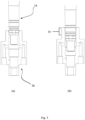
- the insert 20 is indicated which can have any shape and is interchangeable with others provided with the same mechanical system of connection to the upper end of the rod 10, whatever this is.
- the lower end is constituted by an upper portion 14 having the largest diameter D1, below this an intermediate portion 14' has a smaller diameter D2; below the latter, a lower portion 14", just above the position of the locking nut 11, has a diameter D3 that is even smaller.
- the rod 10 also comprises a threaded final portion 14′′′ with a final diameter D4 smaller than all the other diameters.
- a first seat 12' is present for a gasket such as, for example, an O-ring 13.
- a second seat 12" is arranged for a second O-ring 13.
- the section of the seats 12'-12" is rounded, i.e. completely lacking sharp corners.
- the threaded final portion 14′′′ of the rod 10 is engaged with an adjustment nut 11 which, when inserted in the recess 32 of the rod-carrier device 30, encounters an abutment profile 37.
- the adjustment of the height of the nut 11 on the rod 10 will thus determine the projection of the rod 10 and of the relative insert 20.
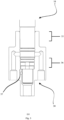
- the recess 32 of the rod-carrier device 30 is configured in four sections corresponding to the four portions of the rod 10 plus an upper rounded part and two intermediate parts that act as a slide during the coupling.
- An upper portion 33 has the largest diameter I1. Below this, an intermediate portion 33' has a smaller diameter I2 and, below this, a lower portion 33" has an even smaller diameter I3.
- the final portion 33′′′ of the rod-carrier 30 finally has a fourth diameter I4 that is smaller than all the others, adapted to house the final portion 14′′′ of the rod 10.
- the size ratios between the diameters of the rod and the diameters of the rod-carrier have been designed to allow the vertical sliding of the rod 10, preventing the contact and the wear of said gaskets 13.
- A as the coupling tolerance between the diameters of the rod, the diameters of the rod-carrier device and all the diameters that are encountered during the mounting and the disassembly of the rod 10 in the rod-carrier 30 and from the mold
- B as the tolerance between gaskets 13 and all the diameters that are encountered during the mounting and the disassembly of the rod 10 in the rod-carrier 30 and from the mold
- the contact area 35 between the rod-carrier 30 and the rod 10 is suitably adjusted with respect to the diameter and height in a manner such to prevent the formation of cracks due to the bending of the rod during the working thereof.
- the rod-carrier device 30 in its preferred embodiment, also comprises a cooling circuit 31 provided with outlet nozzles for water at said upper portion 33 of the recess 32.
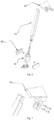
- a final, but not less important expedient regards the sliding plates 40 which are engaged laterally to said rod-carrier device 30.
- These are configured, in the preferred embodiment, with a hinge-like constraint 41 adapted to allow 2 degrees of freedom, generating a rolling friction and hence protecting the mechanism from an early wear which would be due to a sliding friction.
Landscapes
- Engineering & Computer Science (AREA)
- Manufacturing & Machinery (AREA)
- Mechanical Engineering (AREA)
- Physics & Mathematics (AREA)
- Fluid Mechanics (AREA)
- Moulds For Moulding Plastics Or The Like (AREA)
- Injection Moulding Of Plastics Or The Like (AREA)
- Mutual Connection Of Rods And Tubes (AREA)
Applications Claiming Priority (2)
| Application Number | Priority Date | Filing Date | Title |
|---|---|---|---|
| IT102019000025219A IT201900025219A1 (it) | 2019-12-23 | 2019-12-23 | Sciabola per stampi termoplastici |
| PCT/IB2020/062194 WO2021130633A1 (en) | 2019-12-23 | 2020-12-18 | Saber-like element for thermoplastic molds |
Publications (3)
| Publication Number | Publication Date |
|---|---|
| EP4061606A1 EP4061606A1 (en) | 2022-09-28 |
| EP4061606C0 EP4061606C0 (en) | 2023-11-01 |
| EP4061606B1 true EP4061606B1 (en) | 2023-11-01 |
Family
ID=70228541
Family Applications (1)
| Application Number | Title | Priority Date | Filing Date |
|---|---|---|---|
| EP20829674.9A Active EP4061606B1 (en) | 2019-12-23 | 2020-12-18 | Saber-like element for thermoplastic molds |
Country Status (5)
| Country | Link |
|---|---|
| EP (1) | EP4061606B1 (pl) |
| ES (1) | ES2972215T3 (pl) |
| IT (1) | IT201900025219A1 (pl) |
| PL (1) | PL4061606T3 (pl) |
| WO (1) | WO2021130633A1 (pl) |
Family Cites Families (7)
| Publication number | Priority date | Publication date | Assignee | Title |
|---|---|---|---|---|
| ES2220158B1 (es) * | 2001-10-29 | 2005-12-16 | Alberto Navarra Pruna | Mecanismo de expulsion para moldes de inyeccion. |
| KR100887386B1 (ko) * | 2008-07-08 | 2009-03-05 | (주) 부광테크 | 코어 유니트 |
| DE102009037981B3 (de) * | 2009-08-19 | 2011-03-03 | Christian Karl Siebenwurst Modellfabrik Und Formenbau Gmbh & Co. Kg | Formvorrichtung und Verfahren zum Entformen eines Gegenstandes |
| CN102873838B (zh) * | 2012-09-25 | 2014-12-17 | 宁波方正汽车模具有限公司 | 一种设有受力台阶的斜顶杆 |
| US10220556B2 (en) * | 2016-06-13 | 2019-03-05 | Progressive Components International Corporation | Molded undercut release apparatus |
| FR3073442B1 (fr) * | 2017-11-15 | 2019-11-01 | Faurecia Interieur Industrie | Dispositif d’ejection pour outil de realisation d’une piece formee avec systeme de refroidissement |
| IT201800003877A1 (it) * | 2018-03-22 | 2019-09-22 | Ermanno Balzi S R L | Dispositivo estrattore per stampi |
-
2019
- 2019-12-23 IT IT102019000025219A patent/IT201900025219A1/it unknown
-
2020
- 2020-12-18 EP EP20829674.9A patent/EP4061606B1/en active Active
- 2020-12-18 WO PCT/IB2020/062194 patent/WO2021130633A1/en not_active Ceased
- 2020-12-18 ES ES20829674T patent/ES2972215T3/es active Active
- 2020-12-18 PL PL20829674.9T patent/PL4061606T3/pl unknown
Also Published As
| Publication number | Publication date |
|---|---|
| EP4061606A1 (en) | 2022-09-28 |
| WO2021130633A1 (en) | 2021-07-01 |
| ES2972215T3 (es) | 2024-06-11 |
| IT201900025219A1 (it) | 2021-06-23 |
| EP4061606C0 (en) | 2023-11-01 |
| PL4061606T3 (pl) | 2024-07-15 |
Similar Documents
| Publication | Publication Date | Title |
|---|---|---|
| US5012839A (en) | Heated plastic flow control valve | |
| US8529820B1 (en) | Adjustable melt rotation positioning device and method | |
| US5329406A (en) | Plastic optical elements and a molding mold therefor | |
| EP4061606B1 (en) | Saber-like element for thermoplastic molds | |
| US20140377398A1 (en) | Device for demolding parts | |
| AU2016204329B2 (en) | Continuous cast molten metal mold and casting system | |
| US20200031031A1 (en) | Undercut Processing Mechanism and Molding Machine | |
| US5776517A (en) | Adjustable mold clamping wedges | |
| KR200442757Y1 (ko) | 금형 자동 클램핑 장치 | |
| CN109803816B (zh) | 模制器具 | |
| CN1287513A (zh) | 耐火注口 | |
| US20110262581A1 (en) | Mold assembly | |
| KR20180095287A (ko) | 사출성형기용 형체장치 및 타이바 잠금위치 보정방법 | |
| EP3708332B1 (en) | Device for demoulding negatives in thermoplastic injection moulds | |
| CN103372635B (zh) | 铸模夹紧装置以及使用该铸模夹紧装置的连续铸造设备 | |
| US20220161472A1 (en) | Injection molding system with conveyor devices to insert or eject molds | |
| JPS63242617A (ja) | 開きコアを有する射出成形金型 | |
| US11285647B2 (en) | Device for securing and/or releasing injection moulds, means and method | |
| KR101828446B1 (ko) | 연속 주조설비용 더미 바 헤드 씰링시스템 | |
| JPS63189218A (ja) | 開きコアを有する射出成形金型 | |
| EP4217176B1 (en) | A mold tool for injection molding | |
| US12600069B2 (en) | Molding and slide apparatus system | |
| EP3820669B1 (en) | Device to adjust the linear position of a shutter | |
| CN210547994U (zh) | 一种压铸模块斜抽芯自锁滑块结构 | |
| WO2025043323A1 (en) | Injection mold with split mold insert movement detector |
Legal Events
| Date | Code | Title | Description |
|---|---|---|---|
| STAA | Information on the status of an ep patent application or granted ep patent |
Free format text: STATUS: UNKNOWN |
|
| STAA | Information on the status of an ep patent application or granted ep patent |
Free format text: STATUS: THE INTERNATIONAL PUBLICATION HAS BEEN MADE |
|
| PUAI | Public reference made under article 153(3) epc to a published international application that has entered the european phase |
Free format text: ORIGINAL CODE: 0009012 |
|
| STAA | Information on the status of an ep patent application or granted ep patent |
Free format text: STATUS: REQUEST FOR EXAMINATION WAS MADE |
|
| 17P | Request for examination filed |
Effective date: 20220620 |
|
| AK | Designated contracting states |
Kind code of ref document: A1 Designated state(s): AL AT BE BG CH CY CZ DE DK EE ES FI FR GB GR HR HU IE IS IT LI LT LU LV MC MK MT NL NO PL PT RO RS SE SI SK SM TR |
|
| DAV | Request for validation of the european patent (deleted) | ||
| DAX | Request for extension of the european patent (deleted) | ||
| GRAP | Despatch of communication of intention to grant a patent |
Free format text: ORIGINAL CODE: EPIDOSNIGR1 |
|
| STAA | Information on the status of an ep patent application or granted ep patent |
Free format text: STATUS: GRANT OF PATENT IS INTENDED |
|
| INTG | Intention to grant announced |
Effective date: 20230614 |
|
| GRAS | Grant fee paid |
Free format text: ORIGINAL CODE: EPIDOSNIGR3 |
|
| GRAA | (expected) grant |
Free format text: ORIGINAL CODE: 0009210 |
|
| STAA | Information on the status of an ep patent application or granted ep patent |
Free format text: STATUS: THE PATENT HAS BEEN GRANTED |
|
| RAP1 | Party data changed (applicant data changed or rights of an application transferred) |
Owner name: ADM S.R.L. |
|
| AK | Designated contracting states |
Kind code of ref document: B1 Designated state(s): AL AT BE BG CH CY CZ DE DK EE ES FI FR GB GR HR HU IE IS IT LI LT LU LV MC MK MT NL NO PL PT RO RS SE SI SK SM TR |
|
| REG | Reference to a national code |
Ref country code: GB Ref legal event code: FG4D |
|
| REG | Reference to a national code |
Ref country code: CH Ref legal event code: EP |
|
| REG | Reference to a national code |
Ref country code: IE Ref legal event code: FG4D |
|
| REG | Reference to a national code |
Ref country code: DE Ref legal event code: R096 Ref document number: 602020020451 Country of ref document: DE |
|
| U01 | Request for unitary effect filed |
Effective date: 20231130 |
|
| U07 | Unitary effect registered |
Designated state(s): AT BE BG DE DK EE FI FR IT LT LU LV MT NL PT SE SI Effective date: 20240105 |
|
| U20 | Renewal fee for the european patent with unitary effect paid |
Year of fee payment: 4 Effective date: 20240102 |
|
| PG25 | Lapsed in a contracting state [announced via postgrant information from national office to epo] |
Ref country code: GR Free format text: LAPSE BECAUSE OF FAILURE TO SUBMIT A TRANSLATION OF THE DESCRIPTION OR TO PAY THE FEE WITHIN THE PRESCRIBED TIME-LIMIT Effective date: 20240202 |
|
| PG25 | Lapsed in a contracting state [announced via postgrant information from national office to epo] |
Ref country code: IS Free format text: LAPSE BECAUSE OF FAILURE TO SUBMIT A TRANSLATION OF THE DESCRIPTION OR TO PAY THE FEE WITHIN THE PRESCRIBED TIME-LIMIT Effective date: 20240301 |
|
| PG25 | Lapsed in a contracting state [announced via postgrant information from national office to epo] |
Ref country code: IS Free format text: LAPSE BECAUSE OF FAILURE TO SUBMIT A TRANSLATION OF THE DESCRIPTION OR TO PAY THE FEE WITHIN THE PRESCRIBED TIME-LIMIT Effective date: 20240301 Ref country code: GR Free format text: LAPSE BECAUSE OF FAILURE TO SUBMIT A TRANSLATION OF THE DESCRIPTION OR TO PAY THE FEE WITHIN THE PRESCRIBED TIME-LIMIT Effective date: 20240202 |
|
| PG25 | Lapsed in a contracting state [announced via postgrant information from national office to epo] |
Ref country code: RS Free format text: LAPSE BECAUSE OF FAILURE TO SUBMIT A TRANSLATION OF THE DESCRIPTION OR TO PAY THE FEE WITHIN THE PRESCRIBED TIME-LIMIT Effective date: 20231101 Ref country code: NO Free format text: LAPSE BECAUSE OF FAILURE TO SUBMIT A TRANSLATION OF THE DESCRIPTION OR TO PAY THE FEE WITHIN THE PRESCRIBED TIME-LIMIT Effective date: 20240201 Ref country code: HR Free format text: LAPSE BECAUSE OF FAILURE TO SUBMIT A TRANSLATION OF THE DESCRIPTION OR TO PAY THE FEE WITHIN THE PRESCRIBED TIME-LIMIT Effective date: 20231101 |
|
| REG | Reference to a national code |
Ref country code: ES Ref legal event code: FG2A Ref document number: 2972215 Country of ref document: ES Kind code of ref document: T3 Effective date: 20240611 |
|
| PG25 | Lapsed in a contracting state [announced via postgrant information from national office to epo] |
Ref country code: CZ Free format text: LAPSE BECAUSE OF FAILURE TO SUBMIT A TRANSLATION OF THE DESCRIPTION OR TO PAY THE FEE WITHIN THE PRESCRIBED TIME-LIMIT Effective date: 20231101 |
|
| PG25 | Lapsed in a contracting state [announced via postgrant information from national office to epo] |
Ref country code: SK Free format text: LAPSE BECAUSE OF FAILURE TO SUBMIT A TRANSLATION OF THE DESCRIPTION OR TO PAY THE FEE WITHIN THE PRESCRIBED TIME-LIMIT Effective date: 20231101 |
|
| PG25 | Lapsed in a contracting state [announced via postgrant information from national office to epo] |
Ref country code: SM Free format text: LAPSE BECAUSE OF FAILURE TO SUBMIT A TRANSLATION OF THE DESCRIPTION OR TO PAY THE FEE WITHIN THE PRESCRIBED TIME-LIMIT Effective date: 20231101 Ref country code: SK Free format text: LAPSE BECAUSE OF FAILURE TO SUBMIT A TRANSLATION OF THE DESCRIPTION OR TO PAY THE FEE WITHIN THE PRESCRIBED TIME-LIMIT Effective date: 20231101 Ref country code: CZ Free format text: LAPSE BECAUSE OF FAILURE TO SUBMIT A TRANSLATION OF THE DESCRIPTION OR TO PAY THE FEE WITHIN THE PRESCRIBED TIME-LIMIT Effective date: 20231101 |
|
| REG | Reference to a national code |
Ref country code: CH Ref legal event code: PL |
|
| REG | Reference to a national code |
Ref country code: DE Ref legal event code: R097 Ref document number: 602020020451 Country of ref document: DE |
|
| PG25 | Lapsed in a contracting state [announced via postgrant information from national office to epo] |
Ref country code: MC Free format text: LAPSE BECAUSE OF FAILURE TO SUBMIT A TRANSLATION OF THE DESCRIPTION OR TO PAY THE FEE WITHIN THE PRESCRIBED TIME-LIMIT Effective date: 20231101 |
|
| PG25 | Lapsed in a contracting state [announced via postgrant information from national office to epo] |
Ref country code: MC Free format text: LAPSE BECAUSE OF FAILURE TO SUBMIT A TRANSLATION OF THE DESCRIPTION OR TO PAY THE FEE WITHIN THE PRESCRIBED TIME-LIMIT Effective date: 20231101 |
|
| PLBE | No opposition filed within time limit |
Free format text: ORIGINAL CODE: 0009261 |
|
| STAA | Information on the status of an ep patent application or granted ep patent |
Free format text: STATUS: NO OPPOSITION FILED WITHIN TIME LIMIT |
|
| 26N | No opposition filed |
Effective date: 20240802 |
|
| REG | Reference to a national code |
Ref country code: IE Ref legal event code: MM4A |
|
| PG25 | Lapsed in a contracting state [announced via postgrant information from national office to epo] |
Ref country code: IE Free format text: LAPSE BECAUSE OF NON-PAYMENT OF DUE FEES Effective date: 20231218 |
|
| PG25 | Lapsed in a contracting state [announced via postgrant information from national office to epo] |
Ref country code: CH Free format text: LAPSE BECAUSE OF NON-PAYMENT OF DUE FEES Effective date: 20231231 |
|
| PG25 | Lapsed in a contracting state [announced via postgrant information from national office to epo] |
Ref country code: IE Free format text: LAPSE BECAUSE OF NON-PAYMENT OF DUE FEES Effective date: 20231218 Ref country code: CH Free format text: LAPSE BECAUSE OF NON-PAYMENT OF DUE FEES Effective date: 20231231 |
|
| U20 | Renewal fee for the european patent with unitary effect paid |
Year of fee payment: 5 Effective date: 20241216 |
|
| PG25 | Lapsed in a contracting state [announced via postgrant information from national office to epo] |
Ref country code: RO Free format text: LAPSE BECAUSE OF FAILURE TO SUBMIT A TRANSLATION OF THE DESCRIPTION OR TO PAY THE FEE WITHIN THE PRESCRIBED TIME-LIMIT Effective date: 20231101 |
|
| PG25 | Lapsed in a contracting state [announced via postgrant information from national office to epo] |
Ref country code: CY Free format text: LAPSE BECAUSE OF FAILURE TO SUBMIT A TRANSLATION OF THE DESCRIPTION OR TO PAY THE FEE WITHIN THE PRESCRIBED TIME-LIMIT; INVALID AB INITIO Effective date: 20201218 |
|
| PG25 | Lapsed in a contracting state [announced via postgrant information from national office to epo] |
Ref country code: HU Free format text: LAPSE BECAUSE OF FAILURE TO SUBMIT A TRANSLATION OF THE DESCRIPTION OR TO PAY THE FEE WITHIN THE PRESCRIBED TIME-LIMIT; INVALID AB INITIO Effective date: 20201218 |
|
| PGFP | Annual fee paid to national office [announced via postgrant information from national office to epo] |
Ref country code: GB Payment date: 20251219 Year of fee payment: 6 |
|
| PGFP | Annual fee paid to national office [announced via postgrant information from national office to epo] |
Ref country code: TR Payment date: 20251210 Year of fee payment: 6 |
|
| U20 | Renewal fee for the european patent with unitary effect paid |
Year of fee payment: 6 Effective date: 20251218 |
|
| PGFP | Annual fee paid to national office [announced via postgrant information from national office to epo] |
Ref country code: PL Payment date: 20251205 Year of fee payment: 6 |
|
| PGFP | Annual fee paid to national office [announced via postgrant information from national office to epo] |
Ref country code: ES Payment date: 20260130 Year of fee payment: 6 |