EP4061733B1 - Fermeture de récipient - Google Patents
Fermeture de récipient Download PDFInfo
- Publication number
- EP4061733B1 EP4061733B1 EP20804572.4A EP20804572A EP4061733B1 EP 4061733 B1 EP4061733 B1 EP 4061733B1 EP 20804572 A EP20804572 A EP 20804572A EP 4061733 B1 EP4061733 B1 EP 4061733B1
- Authority
- EP
- European Patent Office
- Prior art keywords
- container closure
- container
- ring
- slots
- closure according
- Prior art date
- Legal status (The legal status is an assumption and is not a legal conclusion. Google has not performed a legal analysis and makes no representation as to the accuracy of the status listed.)
- Active
Links
Images




Classifications
-
- B—PERFORMING OPERATIONS; TRANSPORTING
- B65—CONVEYING; PACKING; STORING; HANDLING THIN OR FILAMENTARY MATERIAL
- B65D—CONTAINERS FOR STORAGE OR TRANSPORT OF ARTICLES OR MATERIALS, e.g. BAGS, BARRELS, BOTTLES, BOXES, CANS, CARTONS, CRATES, DRUMS, JARS, TANKS, HOPPERS, FORWARDING CONTAINERS; ACCESSORIES, CLOSURES, OR FITTINGS THEREFOR; PACKAGING ELEMENTS; PACKAGES
- B65D41/00—Caps, e.g. crown caps or crown seals, i.e. members having parts arranged for engagement with the external periphery of a neck or wall defining a pouring opening or discharge aperture; Protective cap-like covers for closure members, e.g. decorative covers of metal foil or paper
- B65D41/32—Caps or cap-like covers with lines of weakness, tearing-strips, tags, or like opening or removal devices, e.g. to facilitate formation of pouring openings
- B65D41/34—Threaded or like caps or cap-like covers provided with tamper elements formed in, or attached to, the closure skirt
- B65D41/3442—Threaded or like caps or cap-like covers provided with tamper elements formed in, or attached to, the closure skirt with rigid bead or projections formed on the tamper element and coacting with bead or projections on the container
- B65D41/3447—Threaded or like caps or cap-like covers provided with tamper elements formed in, or attached to, the closure skirt with rigid bead or projections formed on the tamper element and coacting with bead or projections on the container the tamper element being integrally connected to the closure by means of bridges
-
- B—PERFORMING OPERATIONS; TRANSPORTING
- B65—CONVEYING; PACKING; STORING; HANDLING THIN OR FILAMENTARY MATERIAL
- B65D—CONTAINERS FOR STORAGE OR TRANSPORT OF ARTICLES OR MATERIALS, e.g. BAGS, BARRELS, BOTTLES, BOXES, CANS, CARTONS, CRATES, DRUMS, JARS, TANKS, HOPPERS, FORWARDING CONTAINERS; ACCESSORIES, CLOSURES, OR FITTINGS THEREFOR; PACKAGING ELEMENTS; PACKAGES
- B65D41/00—Caps, e.g. crown caps or crown seals, i.e. members having parts arranged for engagement with the external periphery of a neck or wall defining a pouring opening or discharge aperture; Protective cap-like covers for closure members, e.g. decorative covers of metal foil or paper
- B65D41/32—Caps or cap-like covers with lines of weakness, tearing-strips, tags, or like opening or removal devices, e.g. to facilitate formation of pouring openings
- B65D41/34—Threaded or like caps or cap-like covers provided with tamper elements formed in, or attached to, the closure skirt
- B65D41/3404—Threaded or like caps or cap-like covers provided with tamper elements formed in, or attached to, the closure skirt with ratchet-and-pawl mechanism between the container and the closure skirt or the tamper element
- B65D41/3409—Threaded or like caps or cap-like covers provided with tamper elements formed in, or attached to, the closure skirt with ratchet-and-pawl mechanism between the container and the closure skirt or the tamper element the tamper element being integrally connected to the closure by means of bridges
-
- B—PERFORMING OPERATIONS; TRANSPORTING
- B65—CONVEYING; PACKING; STORING; HANDLING THIN OR FILAMENTARY MATERIAL
- B65D—CONTAINERS FOR STORAGE OR TRANSPORT OF ARTICLES OR MATERIALS, e.g. BAGS, BARRELS, BOTTLES, BOXES, CANS, CARTONS, CRATES, DRUMS, JARS, TANKS, HOPPERS, FORWARDING CONTAINERS; ACCESSORIES, CLOSURES, OR FITTINGS THEREFOR; PACKAGING ELEMENTS; PACKAGES
- B65D1/00—Rigid or semi-rigid containers having bodies formed in one piece, e.g. by casting metallic material, by moulding plastics, by blowing vitreous material, by throwing ceramic material, by moulding pulped fibrous material or by deep-drawing operations performed on sheet material
- B65D1/02—Bottles or similar containers with necks or like restricted apertures, designed for pouring contents
- B65D1/0223—Bottles or similar containers with necks or like restricted apertures, designed for pouring contents characterised by shape
- B65D1/023—Neck construction
- B65D1/0246—Closure retaining means, e.g. beads, screw-threads
-
- B—PERFORMING OPERATIONS; TRANSPORTING
- B65—CONVEYING; PACKING; STORING; HANDLING THIN OR FILAMENTARY MATERIAL
- B65D—CONTAINERS FOR STORAGE OR TRANSPORT OF ARTICLES OR MATERIALS, e.g. BAGS, BARRELS, BOTTLES, BOXES, CANS, CARTONS, CRATES, DRUMS, JARS, TANKS, HOPPERS, FORWARDING CONTAINERS; ACCESSORIES, CLOSURES, OR FITTINGS THEREFOR; PACKAGING ELEMENTS; PACKAGES
- B65D41/00—Caps, e.g. crown caps or crown seals, i.e. members having parts arranged for engagement with the external periphery of a neck or wall defining a pouring opening or discharge aperture; Protective cap-like covers for closure members, e.g. decorative covers of metal foil or paper
- B65D41/32—Caps or cap-like covers with lines of weakness, tearing-strips, tags, or like opening or removal devices, e.g. to facilitate formation of pouring openings
- B65D41/34—Threaded or like caps or cap-like covers provided with tamper elements formed in, or attached to, the closure skirt
- B65D41/3423—Threaded or like caps or cap-like covers provided with tamper elements formed in, or attached to, the closure skirt with flexible tabs, or elements rotated from a non-engaging to an engaging position, formed on the tamper element or in the closure skirt
- B65D41/3428—Threaded or like caps or cap-like covers provided with tamper elements formed in, or attached to, the closure skirt with flexible tabs, or elements rotated from a non-engaging to an engaging position, formed on the tamper element or in the closure skirt the tamper element being integrally connected to the closure by means of bridges
-
- B—PERFORMING OPERATIONS; TRANSPORTING
- B65—CONVEYING; PACKING; STORING; HANDLING THIN OR FILAMENTARY MATERIAL
- B65D—CONTAINERS FOR STORAGE OR TRANSPORT OF ARTICLES OR MATERIALS, e.g. BAGS, BARRELS, BOTTLES, BOXES, CANS, CARTONS, CRATES, DRUMS, JARS, TANKS, HOPPERS, FORWARDING CONTAINERS; ACCESSORIES, CLOSURES, OR FITTINGS THEREFOR; PACKAGING ELEMENTS; PACKAGES
- B65D2251/00—Details relating to container closures
- B65D2251/10—Details of hinged closures
- B65D2251/1008—Means for locking the closure in open position
-
- B—PERFORMING OPERATIONS; TRANSPORTING
- B65—CONVEYING; PACKING; STORING; HANDLING THIN OR FILAMENTARY MATERIAL
- B65D—CONTAINERS FOR STORAGE OR TRANSPORT OF ARTICLES OR MATERIALS, e.g. BAGS, BARRELS, BOTTLES, BOXES, CANS, CARTONS, CRATES, DRUMS, JARS, TANKS, HOPPERS, FORWARDING CONTAINERS; ACCESSORIES, CLOSURES, OR FITTINGS THEREFOR; PACKAGING ELEMENTS; PACKAGES
- B65D2401/00—Tamper-indicating means
- B65D2401/15—Tearable part of the closure
-
- B—PERFORMING OPERATIONS; TRANSPORTING
- B65—CONVEYING; PACKING; STORING; HANDLING THIN OR FILAMENTARY MATERIAL
- B65D—CONTAINERS FOR STORAGE OR TRANSPORT OF ARTICLES OR MATERIALS, e.g. BAGS, BARRELS, BOTTLES, BOXES, CANS, CARTONS, CRATES, DRUMS, JARS, TANKS, HOPPERS, FORWARDING CONTAINERS; ACCESSORIES, CLOSURES, OR FITTINGS THEREFOR; PACKAGING ELEMENTS; PACKAGES
- B65D2401/00—Tamper-indicating means
- B65D2401/15—Tearable part of the closure
- B65D2401/30—Tamper-ring remaining connected to closure after initial removal
-
- B—PERFORMING OPERATIONS; TRANSPORTING
- B65—CONVEYING; PACKING; STORING; HANDLING THIN OR FILAMENTARY MATERIAL
- B65D—CONTAINERS FOR STORAGE OR TRANSPORT OF ARTICLES OR MATERIALS, e.g. BAGS, BARRELS, BOTTLES, BOXES, CANS, CARTONS, CRATES, DRUMS, JARS, TANKS, HOPPERS, FORWARDING CONTAINERS; ACCESSORIES, CLOSURES, OR FITTINGS THEREFOR; PACKAGING ELEMENTS; PACKAGES
- B65D55/00—Accessories for container closures not otherwise provided for
- B65D55/16—Devices preventing loss of removable closure members
Definitions
- the invention relates to a container closure made of plastic according to the preamble of claim 1 and a container, in particular a plastic bottle, with a container closure according to the invention according to the preamble of claim 16.
- the guarantee ring is connected to a screw cap with predetermined breaking bars which are arranged along its circumference.
- the screw cap comprises a cylindrical jacket and an adjoining cover disk.
- the jacket has an internal thread, whereby the screw cap can be screwed onto a container neck with an external thread.
- the predetermined breaking webs connect the open edge of the cylindrical jacket with the guarantee ring. If the predetermined breaking webs are severed, this indicates that the screw cap has already been unscrewed from the container at least once.
- the guarantee ring In order for the predetermined breaking webs to break when the screw cap is unscrewed, the guarantee ring must be held on the container neck in the axial direction so that the axial distance between the guarantee ring and the screw cap can increase when unscrewing. Therefore, holding means are formed on the inside of the guarantee ring, which engage under a holding ring formed on the container neck and extending outwards in the radial direction.
- the WO 2005/077777 A1 shows an embodiment that is often used.
- the guarantee band is designed so that it can be folded over and the folded part forms the engagement means, which engages under the retaining ring of the container neck.
- the disadvantage is, on the one hand, that folding represents an additional work step and, on the other hand, that the material requirement for the double guarantee band is high.
- holding cams are provided on the inside of the guarantee band, which act as holding means.
- the retaining cams must be designed in such a way that the closure can be removed from a tool. This results in the cams being chamfered or rounded in the engagement area.
- this shape of the bevel has the disadvantage that it counteracts a positive engagement. The retaining cams can therefore slip over the retaining ring under axial load, which prevents the predetermined breaking webs from breaking reliably.
- the US 2001/0015341A1 discloses a plurality of holding means which are designed as flaps.
- the lower edge of the flaps is held on the guarantee ring with a film hinge so that it can pivot in the circumferential direction.
- the upper edge is open and therefore forms a holding edge.
- the retaining edge engages under the retaining ring of the container neck.
- a tamper-evident closure according to the preamble of claim 1 with an outer and an inner cap is disclosed.
- the inner cap has a ring element which is held on the inner cap via predetermined breaking webs before the closure is opened for the first time.
- the ring element is held on the container neck by a plurality of tongues formed on the circumference of the ring.
- the tongues are inclined inwards and reach under a projection formed on the container neck.
- the application force of the closure should be reduced, i.e. H.
- the closure should be able to be pushed open with less force on the container after it has been filled for the first time.
- Another task is to show a closure in which the material consumption is reduced, which leads to a corresponding reduction in costs.
- the invention is characterized in that the guarantee ring has slots distributed over the circumference with an upper edge and a lower edge, the upper edge being formed by a circular arc-shaped section of the guarantee ring and the lower edge being formed by a wall section which is inclined inwards in the radial direction and that the lower edge of each slot forms the engagement means for a positive engagement in an abutment arranged in the area of the container neck. Since the engagement means in the form of the inwardly inclined wall sections are not fully present on the guarantee ring and there are also slots, the shape of which further reduces the use of material, the material requirement for plastic can be significantly reduced by up to 5%.
- the wall section is immovable inwards in the radial direction, whereby the guarantee ring is held on the retaining ring and can only be pulled over this when the guarantee ring is stretched on its circumference.
- the guarantee ring is held so firmly on the retaining ring by the wall sections that the first predetermined breaking webs tear securely before the holder of the wall sections is overcome.
- the wall sections are flexible or movable in the radial outward direction. This allows the wall sections to be removed from the injection mold or injection molding tool with little effort. For the same reason, the application force for impacting the container closure is significantly reduced compared to the prior art. Expansion of the guarantee ring, which can lead to permanent damage to the container closure, is largely prevented during demoulding and impact.
- the wall section has a first section which corresponds to an inclined casing section and has two second sections which connect the first section with the casing.
- the second sections hold the first section firmly and prevent it from moving in the radial direction due to an axial unscrewing force is pulled inside. If the wall section is pressed radially outwards during impact or demolding, the second sections give in in a defined manner because they can be deformed or compressed.
- the second sections are oriented obliquely inwards towards each other.
- the second sections can be deformed in a defined manner in the circumferential direction when the wall section is pressed outwards in the radial direction.
- the deformation is elastic and the wall section automatically returns to its basic position, in which it hooks under the retaining ring.
- the lower edge corresponds to the free edges of the first section and the second section and lies in one plane.
- the lower edge has a spatial extent and not just the extent of a straight line or a line. This enables the positive engagement on the retaining ring to be particularly stable and cannot be released by usual axial opening forces.
- the plane in which the lower edge lies is oriented perpendicular to the central axis of the container closure. This means that the entire lower edge can rest against the retaining ring when the guarantee ring is pulled upwards when unscrewing the screw cap. This embodiment therefore leads to a particularly stable positive connection between the wall section and the retaining ring.
- the inclined wall sections have a reduced wall thickness compared to the rest of the guarantee ring, with the area of the lower edge having the lowest wall thickness.
- This wall thickness dimensioning improves the desired elastic deformability of the wall section radially outwards, thereby further improving the bounceability and demoldability of the container closure.
- the wall thickness of the inclined wall sections decreases in the axial direction starting from the free end of the guarantee ring.
- the wall thickness preferably decreases linearly. As stated in the last paragraph, this allows the desired elastic deformation of the wall section improve radially outwards.
- the area of the lower edge, which protrudes furthest radially inwards, can be particularly easily elastically deformed outwards due to the smallest wall thickness.
- At least two diametrically opposed slots are present. This allows the guarantee ring to be held symmetrically on the retaining ring.
- slots of the same size are arranged at the same distance from one another in a peripheral section of the guarantee ring, and the same number of slots is arranged in a diametrically opposite peripheral section.
- the holding force can be increased and adapted to the force that acts on the wall section when unscrewing.
- the diametrical arrangement of the same number of wall sections distributes the tensile force acting on the guarantee ring symmetrically across the wall sections.
- the slots are advantageously of the same length and each have an opening angle of 15 to 30 degrees and preferably between 23 and 27 degrees on the circumference of the guarantee ring, the lower edges of the slots are of sufficient length for a reliable positive fit on the retaining ring. Wall sections or slots of this length can be easily produced using slides on an injection molding tool.
- the invention is also preferably characterized in that the container closure has at least one retaining strap with a first and second end and a first and second longitudinal side, the first end being permanently connected to the free edge of the jacket and the second end being permanently connected to the guarantee ring connected is.
- the screw cap is held captively on the container or on the guarantee ring after it has been unscrewed from the container neck.
- the combination of the engagement means in the form of the slots or wall sections with at least one retaining strap offers the further advantage that the guarantee strap can only be removed from the container neck if it is destroyed and the container closure is always connected to the container when it is disposed of.
- At least one recess is provided on the guarantee ring, in which the tether is accommodated.
- the at least one recess is provided on a circumferential or ring section of the guarantee ring, which is free of slots.
- the wall sections can ideally be combined with at least one retaining strap. Since the holding force of the wall sections is greatly improved compared to engagement means according to the prior art, the wall sections do not necessarily have to be formed around the guarantee ring, but peripheral sections of the guarantee ring without wall sections can also be present. These peripheral sections offer sufficient space to form at least one tether. This makes it possible to avoid that the retaining strap is arranged above the wall sections, which would inevitably lead to an increased height and increased material consumption.
- second predetermined breaking webs connect the first long side of the tether with the free edge of the casing and third predetermined breaking webs connect the second long side of the tether with the guarantee ring.
- the second and third predetermined breaking webs stabilize the area around the at least one tether. This means that the guarantee ring can still be easily pressed onto the container neck and is not weakened in the area of the retaining strap.
- undamaged second and third predetermined breaking bars together with undamaged first predetermined breaking bars indicate the originally closed, unopened container closure.
- the combination of the slots or wall sections described above with at least one retaining band on the guarantee ring is ideal. This is because for the tether to function perfectly, it must tear off in a defined manner. The stable attachment of the guarantee ring to the retaining ring enables precisely this defined tearing off of the second and third predetermined breaking bars.
- the at least one tether has a length such that when the screw cap is unscrewed, the free edge of the jacket can be locked in one of the slots and is held in the slot by the at least one tether.
- the slots therefore interact directly with the retaining band to hold the screw cap on the guarantee ring.
- the advantage of this type of clamping is that it is independent of the preform or support ring located on the container. Since the support ring can be designed to be variable in terms of diameter and its position on the container neck, clamping it under the support ring has the disadvantage that the length of the retaining band always has to be adapted specifically to the design of the support ring.
- the unscrewed screw cap can be held on the container closure itself and is independent of the container and its support ring and their dimensions.
- two retaining straps are provided, the length of which is such that they pull the free edge into one of the slots when the screw cap is unscrewed, whereby the free edge locks in the slot.
- the two retaining straps are preferably tensioned when the screw cap is held in the slot. This means that the screw cap is held particularly stable and reliably on the guarantee ring. After using the container, the screw cap can be removed from the guarantee ring and screwed back onto the container.
- the jacket expediently lies against the upper edge of the slot and the free edge lies against the first section of the wall section. This means that the screw cap is held firmly and wobble-free on the guarantee ring.
- a further aspect of the invention relates to a container, in particular a plastic tab with a container closure according to the description above.
- the lower edge of each slot advantageously reaches under the retaining ring for a positive engagement.
- the container closure fits all containers, in particular plastic bottles, which have a retaining ring designed for the positive engagement of a guarantee ring.
- the container closure is therefore suitable for all containers that are suitable for standard guarantee closures with a guarantee ring.
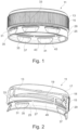
- FIGS. 13 to 16 A container closure is shown, which is designated overall by the reference number 11.
- a first embodiment is shown and in the Figures 5 to 8 a second embodiment is shown.
- a guarantee ring, which the container closure has, is shown separately in FIGS. 13 to 16.
- the container closure 11 has a screw cap 13, which comprises a cylindrical jacket 15 and a cover disk 17 adjoining the jacket 15.
- a sealing element for example a sealing ring 18, can be formed on the inside of the cover disk 17.
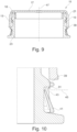
- the jacket 15 has an internal thread 19, which interacts with an external thread 21 of a container neck 23 of a container 24 ( Figure 9 ).
- the sealing ring 18 interacts with the open edge of the container neck 23. As a result, the container 24 is tightly closed when the screw cap 13 is screwed onto the container neck 23.
- the container closure 11 has a guarantee ring 25, which is connected to the free edge 29 of the jacket 15 via first predetermined breaking webs 27.
- first predetermined breaking webs 27 break, which makes it immediately clear whether the container closure is originally closed or not.
- Slots 31 are provided on the guarantee ring distributed over the circumference of the guarantee ring 25.
- the slots 31 each have an upper edge 33 and a lower edge 35.
- the upper edge 33 is formed by an arcuate section of the guarantee ring 25.
- the lower edge 35 corresponds to the free edge of a wall section 37 which is inclined inwards in the radial direction. Due to the inward inclination of the wall section 37, the lower edge 35 has a smaller radius than the guarantee ring 25 and can therefore strike an abutment of the container neck 23 when the screw cap 13 is removed the container neck 23 is unscrewed.
- the abutment is through one Retaining ring 39 is realized, which is formed below the external thread 21 on the container neck 23.
- Each wall section 37 has a first section 41 and two second sections 43.
- the first section 41 represents an inwardly folded jacket section and is preferably flat.
- the second sections 43 adjoin the inward-facing sides of the first section 41 and connect this to the jacket 15.
- the second sections 43 can be curved or flat and face one another obliquely inwards.
- the lower edge 35 of the slot 31 corresponds to the free edges of the first section 41 and the second section 43 and lies in a plane 45 which is in Figure 10 and 16 is shown.
- the plane 45 is preferably oriented perpendicular to the central axis 47 of the container closure 11.
- the inclined wall sections 37 have a reduced wall thickness compared to the rest of the guarantee ring 25. Especially in the Figure 10 it is shown that the area of the lower edge 35 has the smallest wall thickness. As a result, the flexibility of the wall section 37 described above is further radially outwards improved. The wall thickness of the wall section 37 increases linearly downwards starting from the lower edge 35.
- Figure 4 shows that preferably in a peripheral section of the guarantee ring 25 several slots 31 of the same size are arranged at the same distance from one another and that the same number of slots 31 is arranged in a diametrically opposite peripheral section.
- the holding forces of the wall sections are distributed as evenly as possible over the circumference of the guarantee ring 25.
- two free ring sections 49 are provided, which do not have any slots 31.
- the injection molding tool for producing the container closure 11 has two slides. The sliders create the slots 31 and the wall sections 37.
- FIGS. 5 to 7 and especially that Figure 8 show a second exemplary embodiment in which the slots 31 or the wall sections 37 can be evenly distributed over the circumference of the guarantee ring. In this exemplary embodiment, there are therefore no free ring sections 49 present.
- This embodiment is preferably produced with an injection molding tool with 4 slides.
- the slots 31 are preferably all the same length and have an opening angle 51 which is preferably 25 degrees.
- the lower edges 35 have sufficient length for the reliable and non-detachable holding of the guarantee ring 25 on the container neck 23.
- FIG. 12 An exemplary embodiment is shown in which at least one tether 53 is integrated into the guarantee ring 25.
- the tether 53 has a first and second end and a first and second long side.
- the first end 55 is firmly or permanently connected to the free edge 29 and the second end 57 is firmly or permanently connected to the guarantee ring 25.
- the screw cap 13 is captively connected to the container neck 23 by the retaining strap after it has been unscrewed for the first time and the screw cap 13 must therefore be disposed of together with the container 24.
- a recess 63 is expediently provided on the free ring section 49.
- the tether 53 is accommodated in the recess 63.
- the free ring section 49 offers sufficient space so that the retaining band 53 is integrated into the guarantee ring 25 without the height of the guarantee ring having to be increased or more material being required. It goes without saying that if there are several retaining straps 53, several recesses 63 are provided to accommodate them.
- Second predetermined breaking webs 65 connect the first longitudinal side 59 of the tether 53 with the free edge 29 of the jacket.
- Third predetermined breaking webs 67 connect the second longitudinal sides 59 of the retaining band 53 with the guarantee ring 25.
- the undamaged second and third predetermined breaking webs 65, 67 like the first predetermined breaking webs 27, indicate the original closure of the container closure.
- the second and third predetermined breaking webs 65, 67 are required so that the container closure 11 is sufficiently stable, even if at least one retaining strap 53 is provided, in order to be able to be bounced onto the container closure 11.
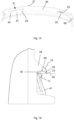
- the first angle of inclination 71 indicates the inclination of the first section 41 relative to the plane of the lower edge 45.
- the first angle of inclination 71 has a size between 60 and 80 degrees and preferably between 65 and 75 degrees. The larger the first angle of inclination 71, the better the stability of the wall sections 37 against vertical forces or axial tensile forces caused by unscrewing the screw cap 13. However, the first angle of inclination 71 must not become too large, otherwise the retaining ring 39 will not be sufficient can be undermined.
- the second angle of inclination 73 indicates the inclination of the slot 31 relative to the plane of the lower edge 45.
- the connecting line 75 which represents the inclination of the slot, is a connection of the upper edge 33 with the lower edge 35 in a plane which is spanned by the central axis 47 and the connecting line 75.
- the second Inclination angle 73 is enclosed by the connecting line 75 and the plane 45.
- the second angle of inclination 73 has a size between 30 and 50 degrees and preferably between 35 and 45 degrees. The larger the second angle of inclination 73, the easier it is to demold the container closure 11.
- the wall sections 37 enable the guarantee ring 25 to be reliably held on the container neck 23, even if increased axial forces act when unscrewing the screw cap 13, which pull the guarantee ring 25 upwards. Accordingly, the predetermined breaking webs 27, 65, 67 tear reliably before the guarantee ring 25 is pulled over the retaining ring 39.
- the design of the wall sections 37 enables the container closure to be removed from its tool non-destructively and to be pressed onto the container neck 23 with reduced application force (compared to the prior art). This is due to the fact that the wall sections 37 are immovable in the radial inward direction, but have a certain mobility in the radial outward direction.
- the combination of the slots 31 or wall sections 37 with at least one retaining band 53 on the guarantee ring 27 offers great advantages. This is because for the at least one tether 53 to function perfectly, it must tear off in a defined manner. The particularly stable attachment of the guarantee ring 25 to the retaining ring 39 enables precisely this defined tearing off of the second and third predetermined breaking webs 65,67.
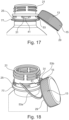
- a variant is shown as to how the unscrewed screw cap 13 can be held on the container 24.
- the at least one tether 53 has such a length that the free edge 29 can be held in one of the slots 31.
- the screw cap 13 is fixed by dimensioning the length of the retaining band 53, so that it does not interfere with the filling material being poured out.
- the slots 31 and the retaining band 53 therefore work together directly so that the screw cap 13 can be fixed.
- the slots 31 therefore have another use in addition to reliably holding the guarantee ring 25. Because the screw cap 13 can be held on the guarantee ring 25, a holder on the support ring 77, which is formed on the container neck 23, is obsolete.
- the tether The length of 53 therefore does not have to be adapted to different diameters and positions of the support ring 77, but can always have the same length.
- FIG. 18 A further embodiment is shown, in which the free edge 29 is pulled into the slot by a first and second retaining band 53a, 53b.
- the retaining straps 53a, 53b are preferably tensioned so that the screw cap 13 is held firmly on the slot 31.
- the free edge 29 is preferably pulled onto the slot 31 in such a way that the jacket 15 rests on the upper edge 33 of the slot 31 and the free edge 29 rests on the first section 41 of the wall section 37.
Landscapes
- Engineering & Computer Science (AREA)
- Mechanical Engineering (AREA)
- Ceramic Engineering (AREA)
- Closures For Containers (AREA)
Claims (18)
- Fermeture de récipient (11) en matière plastique pour fermer un récipient (24) avec- un capuchon à vis (13) qui présente une enveloppe cylindrique (15) avec un filet intérieur (19) et un disque de couvercle (17) qui se rattache à l'enveloppe (15) et- un anneau de garantie (25),- qui est relié au bord libre (29) de l'enveloppe (15) par de premières pattes de rupture (27),- qui présente un moyen d'engrènement (35) qui est configurés pour un engrènement par complémentarité de formes dans un contrefort en forme d'anneau de retenue (39) placé dans la zone du col du récipient (23) et- qui présente des fentes (31) placées en étant réparties sur la circonférence avec une arête supérieure (33) et une arête inférieure (35), cependant que- l'arête supérieure (33) est formée par une portion de l'anneau de garantie (25) qui s'étend en forme d'arc de cercle et l'arête inférieure (35) est formée par une portion de paroi inclinée vers l'intérieur dans le sens radial avec une première portion partielle (41), laquelle portion partielle (41) correspond à une portion d'enveloppe placée en biais et- l'arête inférieure (35) de chaque fente (31) forme le moyen d'engrènement pour un engrènement par complémentarité de formes dans un contrefort (39) placé dans la zone du col du récipient (23),caractérisée en ce
que la portion de paroi (37) présente deux secondes portions partielles (43) qui relient la première portion partielle (41) à l'enveloppe (15). - Fermeture de récipient selon la revendication 1, caractérisée en ce que les secondes portions partielles (43) sont orientées en étant tournées l'une vers l'autre en biais vers l'intérieur.
- Fermeture de récipient selon la revendication 1 ou 2, caractérisée en ce que l'arête inférieure (35) correspond aux bords libres de la première portion partielle (41) et des secondes portions partielles (43) et se situe dans un plan (45).
- Fermeture de récipient selon la revendication 3, caractérisée en ce que le plan (45) dans lequel se situe l'arête inférieure (35) est orienté perpendiculairement à l'axe central (47) de la fermeture de récipient (11).
- Fermeture de récipient selon l'une des revendications précédentes, caractérisée en ce que les portions de paroi inclinées (37) présentent une épaisseur de paroi réduite par rapport au reste de l'anneau de garantie (25), cependant que la zone de l'arête inférieure (35) présente l'épaisseur de paroi la plus faible.
- Fermeture de récipient selon l'une des revendications précédentes, caractérisée en ce que l'épaisseur de paroi des portions de paroi inclinées (37) diminue dans le sens axial en partant de l'extrémité libre de l'anneau de garantie (25).
- Fermeture de récipient selon l'une des revendications précédentes, caractérisée en ce qu'il existe au moins deux fentes (31) diamétralement opposées l'une à l'autre.
- Fermeture de récipient selon l'une des revendications précédentes, caractérisée en ce que plusieurs fentes de même taille (31) sont placées équidistantes dans une portion de la circonférence de l'anneau de garantie (31) et que le même nombre de fentes (31) est placé dans une portion de la circonférence diamétralement opposée.
- Fermeture de récipient selon l'une des revendications précédentes, caractérisée en ce que les fentes (31) sont réparties de manière régulière sur la circonférence de l'anneau de garantie (25).
- Fermeture de récipient selon l'une des revendications précédentes, caractérisée en ce que les fentes (31) sont de même longueur et présentent chacune un angle d'ouverture (51) de 15 à 30 degrés et de préférence entre 23 et 27 degrés sur la circonférence de l'anneau de garantie (25).
- Fermeture de récipient selon l'une des revendications précédentes, caractérisée en ce que la fermeture de récipient (11) présente au moins une bande de retenue (53) avec une première et une seconde extrémité (55, 57) et un premier et un second long côté (59, 61), cependant que la première extrémité (55) est reliée de manière inamovible au bord libre (29) de l'enveloppe (15) et la seconde extrémité (57) est reliée de manière inamovible à l'anneau de garantie (25).
- Fermeture de récipient selon la revendication 11, caractérisée en ce que la au moins une bande de retenue (53) présente une longueur telle qu'à l'état dévissé du capuchon à vis (13) le bord libre (29) de l'enveloppe (15) peut être enclenché dans l'une des fentes (31) et est maintenu dans la fente (31) par la au moins une bande de retenue (53).
- Fermeture de récipient selon la revendication 12, caractérisée en ce que deux bandes de retenue (31) sont prévues dont la longueur est dimensionnée telle qu'elles tirent le bord libre (29, à l'état dévissé du capuchon à vis (13), dans l'une des fentes (31) si bien que le bord libre (29) s'enclenche dans la fente (31).
- Fermeture de récipient selon la revendication 12 ou 13, caractérisée en ce que l'enveloppe (15) repose contre l'arête supérieure (33) de la fente (31) et le bord libre (29) repose contre la première portion partielle (41) de la portion de paroi (37).
- Fermeture de récipient selon l'une des revendications 11 à 14, caractérisée en ce qu'il est prévu au moins un évidement (63) sur l'anneau de retenue (25), évidement dans lequel la bande de retenue (53) est logée.
- Fermeture de récipient selon la revendication 15, caractérisée en ce que le au moins un évidement (63) est prévu sur une portion de la circonférence ou d'anneau (49) de l'anneau de garantie (25) qui est exempte de fentes (31).
- Fermeture de récipient selon l'une des revendications 11 à 16, caractérisée en ce que des secondes pattes de rupture (65) relient le premier long côté (59) de la bande de retenue (53) au bord libre (29) de l'enveloppe (15) et des troisièmes pattes de rupture (67) relient le second long côté (61) de la bande de retenue (53) à l'anneau de garantie (25).
- Récipient, en particulier bouteille en matière plastique, cependant que le récipient (24)- présente un col de récipient (23) avec un filet extérieur (21) et un anneau de retenue (39) qui fait saillie radialement vers l'extérieur et- une fermeture de récipient (11),caractérisé en ceque la fermeture de récipient est la fermeture de récipient selon l'une des revendications précédentes etque l'arête inférieure (35) de chaque fente (31) se met en prise avec l'anneau de retenue (39 par en dessous pour un engrènement par complémentarité de formes.
Priority Applications (1)
| Application Number | Priority Date | Filing Date | Title |
|---|---|---|---|
| RS20240335A RS65312B1 (sr) | 2019-11-20 | 2020-11-17 | Zatvarač kontejnera |
Applications Claiming Priority (4)
| Application Number | Priority Date | Filing Date | Title |
|---|---|---|---|
| CH14672019 | 2019-11-20 | ||
| CH01695/19A CH716870A2 (de) | 2019-11-20 | 2019-12-23 | Behälterverschluss. |
| CH00601/20A CH716855A2 (de) | 2019-11-20 | 2020-05-18 | Behälterverschluss. |
| PCT/EP2020/082391 WO2021099310A2 (fr) | 2019-11-20 | 2020-11-17 | Fermeture de récipient |
Publications (3)
| Publication Number | Publication Date |
|---|---|
| EP4061733A2 EP4061733A2 (fr) | 2022-09-28 |
| EP4061733C0 EP4061733C0 (fr) | 2024-02-21 |
| EP4061733B1 true EP4061733B1 (fr) | 2024-02-21 |
Family
ID=73344090
Family Applications (1)
| Application Number | Title | Priority Date | Filing Date |
|---|---|---|---|
| EP20804572.4A Active EP4061733B1 (fr) | 2019-11-20 | 2020-11-17 | Fermeture de récipient |
Country Status (12)
| Country | Link |
|---|---|
| US (1) | US12297010B2 (fr) |
| EP (1) | EP4061733B1 (fr) |
| CN (1) | CN114650953A (fr) |
| BR (1) | BR112022009775A2 (fr) |
| CH (1) | CH716855A2 (fr) |
| CO (1) | CO2022006598A2 (fr) |
| MX (1) | MX2022005683A (fr) |
| PL (1) | PL4061733T3 (fr) |
| RS (1) | RS65312B1 (fr) |
| SA (1) | SA522432569B1 (fr) |
| WO (1) | WO2021099310A2 (fr) |
| ZA (1) | ZA202205237B (fr) |
Families Citing this family (7)
| Publication number | Priority date | Publication date | Assignee | Title |
|---|---|---|---|---|
| WO2020212426A1 (fr) * | 2019-04-15 | 2020-10-22 | Alpla Werke Alwin Lehner Gmbh & Co. Kg | Fermeture de récipient |
| ES1281455Y (es) * | 2021-07-29 | 2022-02-01 | Sanchez Jose Francisco Gonzalez | Tapón de cierre para envases |
| ES1279073U (es) * | 2021-08-27 | 2021-10-13 | Sanchez Jose Francisco Gonzalez | Tapón de cierre enroscable para envases y un envase provisto de dicho tapón |
| DE102021125520A1 (de) * | 2021-10-01 | 2023-04-06 | Bericap Holding Gmbh | Verschlussvorrichtung mit Stützring |
| USD1054288S1 (en) * | 2022-09-09 | 2024-12-17 | Alpla Werke Alwin Lehner Gmbh & Co. Kg | Bottle cap |
| SE547849C2 (en) * | 2022-12-20 | 2025-12-09 | Emballator Vaexjoe Ab | A cap with a threaded portion for securing said cap to a bottle, the bottle and a method for manufacturing such a cap |
| EP4600172A1 (fr) * | 2024-02-12 | 2025-08-13 | Betapack, S.A.U. | Capuchon articulé léger |
Family Cites Families (49)
| Publication number | Priority date | Publication date | Assignee | Title |
|---|---|---|---|---|
| US3568871A (en) * | 1969-05-12 | 1971-03-09 | Jay G Livingstone | Closure cap |
| FR2134264B1 (fr) * | 1971-04-29 | 1974-03-08 | Scal Gp Condit Aluminium | |
| FR2329536A1 (fr) * | 1973-07-02 | 1977-05-27 | Somepla Sa | Nouvelle capsule a vis inviolable et imperdable |
| AU516094B2 (en) * | 1977-12-14 | 1981-05-14 | Metal Closures Group Limited | Closures for containers |
| US4572388A (en) * | 1985-03-18 | 1986-02-25 | Sunbeam Plastics Corporation | Tamper indicating screw cap |
| DE3515719A1 (de) | 1985-05-02 | 1986-11-06 | Fa. Friedrich H. Weischede, 4250 Bottrop | Aus kunststoff gefertigter garantieverschluss fuer behaelter und verfahren zum herstellen des garantieverschlusses |
| USRE32879E (en) * | 1988-02-24 | 1989-02-28 | Sunbeam Plastics Corporation | Tamper indicating screw cap |
| US4863050A (en) * | 1988-09-16 | 1989-09-05 | Owens-Illinois Closure Inc. | Tamper indicating package and molded plastic threaded closure therefor |
| US20050269282A1 (en) * | 1990-08-09 | 2005-12-08 | Portola Packaging, Inc. | Tamper-evident cap and container neck |
| US5975321A (en) * | 1990-08-09 | 1999-11-02 | Portola Packaging, Inc. | Snap-on, screw-off cap with tamper-evidencing skirt and container neck |
| US5630520A (en) * | 1990-08-09 | 1997-05-20 | Portola Packaging, Inc. | Tabs for container closures and container neck |
| US5267661A (en) * | 1990-08-09 | 1993-12-07 | Portola Packaging, Inc. | Snap-on, screw off cap and container neck |
| DE4212627A1 (de) | 1992-04-15 | 1993-10-28 | Mouldtec Pvg Ag Meilen | Flaschenkappe mit Sicherungsring |
| AU683857B2 (en) * | 1992-11-13 | 1997-11-27 | Beeson And Sons Limited | Improvements relating to a tamper evident ring for a container closure |
| JP3284388B2 (ja) * | 1994-02-23 | 2002-05-20 | 日本クラウンコルク株式会社 | 合成樹脂製シェルと合成樹脂製ライナーとを具備する容器蓋 |
| AUPO297196A0 (en) | 1996-10-15 | 1996-11-07 | G.V. Engineering Pty. Ltd. | Tamper evident closure |
| US7344039B2 (en) * | 1998-08-07 | 2008-03-18 | Berry Plastics Corporation | Tamper indicating band having foldable tabs including tab extensions, tamper indicating closure including such tamper indicating band, and tamper indicating closure including such tamper indicating band and container |
| US6119883A (en) * | 1998-12-07 | 2000-09-19 | Owens-Illinois Closure Inc. | Tamper-indicating closure and method of manufacture |
| AUPQ365899A0 (en) * | 1999-10-26 | 1999-11-18 | Amcor Packaging (Australia) Pty Ltd | A tamper evident closure |
| JP3338676B2 (ja) * | 1999-10-28 | 2002-10-28 | 天龍化学工業株式会社 | 合成樹脂製のピルファープルーフキャップ |
| KR20010096600A (ko) * | 2000-03-13 | 2001-11-07 | 도케 케이시 | 합성수지제 용기뚜껑 |
| US6382445B1 (en) * | 2000-06-23 | 2002-05-07 | Alcoa Closure Systems International | Linerless closure with pressure seal holding feature |
| US6695161B2 (en) * | 2001-02-08 | 2004-02-24 | Japan Crown Cork Co., Ltd. | Plastic container closure |
| US20020166859A1 (en) * | 2001-05-14 | 2002-11-14 | Mcgrew Henry E. | Tank vent cap |
| US20050006334A1 (en) * | 2001-06-07 | 2005-01-13 | Rexam Medical Packaging Inc. | Double shell closure with support ribs |
| WO2005077777A1 (fr) | 2004-02-18 | 2005-08-25 | Abacus (C.I.) Limited As Trustee Of The Bayview Trust | Fermeture dotee d'un manchon temoin d'inviolabilite destructible |
| US20050252878A1 (en) * | 2004-05-03 | 2005-11-17 | Alcoa Closure Systems International | Tamper-evident package |
| CN1830730A (zh) * | 2005-01-01 | 2006-09-13 | 郭永军 | 铰接式防盗瓶盖 |
| ITMO20060029A1 (it) * | 2006-01-27 | 2007-07-28 | Sacmi | Mezzi di chiusura |
| US8302794B2 (en) * | 2006-04-28 | 2012-11-06 | Berry Plastics Corporation | Tamper-evident closure with directional molded retention tabs |
| JP4912829B2 (ja) * | 2006-10-17 | 2012-04-11 | 日本クラウンコルク株式会社 | 容器蓋 |
| ES2365529T3 (es) * | 2006-11-10 | 2011-10-06 | Guala Closures S.P.A. | Un cierre contra la manipulación indebida. |
| EP1953091A1 (fr) * | 2007-01-31 | 2008-08-06 | Obrist Closures Switzerland GmbH | Capuchon de fermeture anti-sabotage, conteneur et combinaison correspondante |
| JP4925382B2 (ja) * | 2007-03-27 | 2012-04-25 | 日本クラウンコルク株式会社 | タンパーエビデント特性を有する樹脂製容器蓋及びその樹脂製容器蓋の製造方法 |
| EP2088090A1 (fr) | 2008-02-01 | 2009-08-12 | Obrist Closures Switzerland GmbH | Capuchon de fermeture anti-sabotage et combinaison de fermeture et de récipient |
| DE102008014952A1 (de) | 2008-03-19 | 2009-09-24 | Z-Werkzeugbau-Gmbh | Schraubkappe |
| SE0801018L (sv) * | 2008-05-07 | 2009-11-08 | Petro Pack Ab | Förpackningsförslutning |
| EP2481679A4 (fr) * | 2010-01-12 | 2015-05-06 | Chwei-Jei Tsai | Couvercle de bouteille en polyéthylène téréphtalate et son procédé de fabrication |
| US8459486B2 (en) * | 2010-04-19 | 2013-06-11 | Ropak Corporation | Container and lid |
| FR2974790B1 (fr) * | 2011-05-04 | 2013-06-21 | Tetra Laval Holdings & Finance | Bouchon pour un col de recipient |
| US20130200036A1 (en) * | 2012-02-07 | 2013-08-08 | Plastipak Packaging, Inc. | Container seal closure and assembly |
| FR2987607B1 (fr) * | 2012-03-05 | 2015-07-24 | Tetra Laval Holdings & Finance | Bouchon pour un col de recipient |
| AU2013292280A1 (en) * | 2012-07-20 | 2015-01-29 | Closure Systems International Inc. | Lightweight closure and container package |
| JP6442415B2 (ja) * | 2012-12-27 | 2018-12-19 | ジーイー・ヘルスケア・アクスイェ・セルスカプ | 開封明示容器キャップアセンブリ |
| US20140263335A1 (en) * | 2013-03-14 | 2014-09-18 | Silgan White Cap LLC | Internal, multi-seal plastic closure |
| ITPS20130014A1 (it) * | 2013-08-29 | 2015-03-01 | Supercap S R L | Struttura tappo elastomerico sintetico a prova di manomissione e procedimento di relativa produzione |
| US10836549B2 (en) * | 2015-04-02 | 2020-11-17 | Thiscap Inc. | Cap for container |
| CN105173350B (zh) * | 2015-07-30 | 2017-10-31 | 泉州华硕实业有限公司 | 一种易脱模的密封防盗瓶盖及其生产工艺 |
| US20180127159A1 (en) * | 2016-11-04 | 2018-05-10 | Randy Mark Cunningham | Beverage container having fragrant component |
-
2020
- 2020-05-18 CH CH00601/20A patent/CH716855A2/de unknown
- 2020-11-17 US US17/778,702 patent/US12297010B2/en active Active
- 2020-11-17 EP EP20804572.4A patent/EP4061733B1/fr active Active
- 2020-11-17 PL PL20804572.4T patent/PL4061733T3/pl unknown
- 2020-11-17 RS RS20240335A patent/RS65312B1/sr unknown
- 2020-11-17 MX MX2022005683A patent/MX2022005683A/es unknown
- 2020-11-17 BR BR112022009775A patent/BR112022009775A2/pt unknown
- 2020-11-17 CN CN202080080404.XA patent/CN114650953A/zh active Pending
- 2020-11-17 WO PCT/EP2020/082391 patent/WO2021099310A2/fr not_active Ceased
-
2022
- 2022-05-11 ZA ZA2022/05237A patent/ZA202205237B/en unknown
- 2022-05-11 SA SA522432569A patent/SA522432569B1/ar unknown
- 2022-05-18 CO CONC2022/0006598A patent/CO2022006598A2/es unknown
Also Published As
| Publication number | Publication date |
|---|---|
| CO2022006598A2 (es) | 2022-07-29 |
| SA522432569B1 (ar) | 2024-03-25 |
| RS65312B1 (sr) | 2024-04-30 |
| EP4061733C0 (fr) | 2024-02-21 |
| WO2021099310A2 (fr) | 2021-05-27 |
| MX2022005683A (es) | 2022-07-19 |
| CN114650953A (zh) | 2022-06-21 |
| CH716855A2 (de) | 2021-05-31 |
| PL4061733T3 (pl) | 2024-04-22 |
| BR112022009775A2 (pt) | 2022-08-09 |
| ZA202205237B (en) | 2022-12-21 |
| WO2021099310A3 (fr) | 2021-07-15 |
| US20230041392A1 (en) | 2023-02-09 |
| EP4061733A2 (fr) | 2022-09-28 |
| US12297010B2 (en) | 2025-05-13 |
Similar Documents
| Publication | Publication Date | Title |
|---|---|---|
| EP4061733B1 (fr) | Fermeture de récipient | |
| EP4061731B1 (fr) | Fermeture pour conteneur | |
| EP3938288B1 (fr) | Fermeture de contenant et contenant | |
| EP4061736B1 (fr) | Fermeture de récipient | |
| EP0281514B2 (fr) | Capsule de fermeture à bande de garantie | |
| WO2020182854A1 (fr) | Fermeture de contenant et contenant | |
| EP3938289B1 (fr) | Bouchon de fermeture conçu pour fermer un contenant | |
| AT17738U1 (de) | Verschlusskappe zum Verschließen eines Behälters | |
| EP4493484B1 (fr) | Capuchon de fermeture | |
| WO2020182852A1 (fr) | Bouchon de fermeture conçu pour fermer un contenant | |
| WO1994022732A1 (fr) | Bouchage en plastique | |
| AT525129B1 (de) | Behälterverschluss | |
| CH716870A2 (de) | Behälterverschluss. | |
| EP4161845B1 (fr) | Fermeture pour conteneur | |
| WO2020144183A1 (fr) | Capuchon de fermeture pour fermer un contenant | |
| DE212020000504U1 (de) | Verschlusskappe zum Verschliessen eines Behälters | |
| EP0387302B1 (fr) | Fermeture inviolable | |
| EP4037989B1 (fr) | Fermeture de récipient | |
| CH716074A1 (de) | Verschlusskappe zum Verschliessen eines Behälters und Behälter mit einer solchen unverlierbar gehaltenen Verschlusskappe. | |
| EP3908533B1 (fr) | Capuchon de fermeture pour fermer un contenant | |
| EP0103567A2 (fr) | Capuchon à vis en matière plastique et dispositif pour fermer un récipient avec un tel capuchon | |
| EP4463398B1 (fr) | Capuchon de fermeture | |
| EP1529005A1 (fr) | Dispositif de fermeture/deversement combine comprenant une securite d'authenticite | |
| CH716317A2 (de) | Behälterverschluss zum Verschliessen der Ausgiessöffnung eines Behälters und Behälter mit einem solchen unverlierbar gehaltenen Behälterverschluss. | |
| DE20120965U1 (de) | Originalitätsverschluss |
Legal Events
| Date | Code | Title | Description |
|---|---|---|---|
| STAA | Information on the status of an ep patent application or granted ep patent |
Free format text: STATUS: UNKNOWN |
|
| STAA | Information on the status of an ep patent application or granted ep patent |
Free format text: STATUS: THE INTERNATIONAL PUBLICATION HAS BEEN MADE |
|
| PUAI | Public reference made under article 153(3) epc to a published international application that has entered the european phase |
Free format text: ORIGINAL CODE: 0009012 |
|
| STAA | Information on the status of an ep patent application or granted ep patent |
Free format text: STATUS: REQUEST FOR EXAMINATION WAS MADE |
|
| 17P | Request for examination filed |
Effective date: 20220620 |
|
| AK | Designated contracting states |
Kind code of ref document: A2 Designated state(s): AL AT BE BG CH CY CZ DE DK EE ES FI FR GB GR HR HU IE IS IT LI LT LU LV MC MK MT NL NO PL PT RO RS SE SI SK SM TR |
|
| DAV | Request for validation of the european patent (deleted) | ||
| DAX | Request for extension of the european patent (deleted) | ||
| GRAP | Despatch of communication of intention to grant a patent |
Free format text: ORIGINAL CODE: EPIDOSNIGR1 |
|
| STAA | Information on the status of an ep patent application or granted ep patent |
Free format text: STATUS: GRANT OF PATENT IS INTENDED |
|
| INTG | Intention to grant announced |
Effective date: 20230904 |
|
| GRAS | Grant fee paid |
Free format text: ORIGINAL CODE: EPIDOSNIGR3 |
|
| GRAA | (expected) grant |
Free format text: ORIGINAL CODE: 0009210 |
|
| STAA | Information on the status of an ep patent application or granted ep patent |
Free format text: STATUS: THE PATENT HAS BEEN GRANTED |
|
| AK | Designated contracting states |
Kind code of ref document: B1 Designated state(s): AL AT BE BG CH CY CZ DE DK EE ES FI FR GB GR HR HU IE IS IT LI LT LU LV MC MK MT NL NO PL PT RO RS SE SI SK SM TR |
|
| RAP3 | Party data changed (applicant data changed or rights of an application transferred) |
Owner name: ALPLA WERKE ALWIN LEHNER GMBH & CO. KG |
|
| REG | Reference to a national code |
Ref country code: GB Ref legal event code: FG4D Free format text: NOT ENGLISH |
|
| REG | Reference to a national code |
Ref country code: CH Ref legal event code: EP |
|
| REG | Reference to a national code |
Ref country code: DE Ref legal event code: R096 Ref document number: 502020007118 Country of ref document: DE |
|
| REG | Reference to a national code |
Ref country code: IE Ref legal event code: FG4D Free format text: LANGUAGE OF EP DOCUMENT: GERMAN |
|
| U01 | Request for unitary effect filed |
Effective date: 20240319 |
|
| U07 | Unitary effect registered |
Designated state(s): AT BE BG DE DK EE FI FR IT LT LU LV MT NL PT SE SI Effective date: 20240326 |
|
| PG25 | Lapsed in a contracting state [announced via postgrant information from national office to epo] |
Ref country code: IS Free format text: LAPSE BECAUSE OF FAILURE TO SUBMIT A TRANSLATION OF THE DESCRIPTION OR TO PAY THE FEE WITHIN THE PRESCRIBED TIME-LIMIT Effective date: 20240621 |
|
| PG25 | Lapsed in a contracting state [announced via postgrant information from national office to epo] |
Ref country code: GR Free format text: LAPSE BECAUSE OF FAILURE TO SUBMIT A TRANSLATION OF THE DESCRIPTION OR TO PAY THE FEE WITHIN THE PRESCRIBED TIME-LIMIT Effective date: 20240522 |
|
| PG25 | Lapsed in a contracting state [announced via postgrant information from national office to epo] |
Ref country code: HR Free format text: LAPSE BECAUSE OF FAILURE TO SUBMIT A TRANSLATION OF THE DESCRIPTION OR TO PAY THE FEE WITHIN THE PRESCRIBED TIME-LIMIT Effective date: 20240221 |
|
| REG | Reference to a national code |
Ref country code: ES Ref legal event code: FG2A Ref document number: 2976053 Country of ref document: ES Kind code of ref document: T3 Effective date: 20240722 |
|
| PG25 | Lapsed in a contracting state [announced via postgrant information from national office to epo] |
Ref country code: NO Free format text: LAPSE BECAUSE OF FAILURE TO SUBMIT A TRANSLATION OF THE DESCRIPTION OR TO PAY THE FEE WITHIN THE PRESCRIBED TIME-LIMIT Effective date: 20240521 Ref country code: IS Free format text: LAPSE BECAUSE OF FAILURE TO SUBMIT A TRANSLATION OF THE DESCRIPTION OR TO PAY THE FEE WITHIN THE PRESCRIBED TIME-LIMIT Effective date: 20240621 Ref country code: HR Free format text: LAPSE BECAUSE OF FAILURE TO SUBMIT A TRANSLATION OF THE DESCRIPTION OR TO PAY THE FEE WITHIN THE PRESCRIBED TIME-LIMIT Effective date: 20240221 Ref country code: GR Free format text: LAPSE BECAUSE OF FAILURE TO SUBMIT A TRANSLATION OF THE DESCRIPTION OR TO PAY THE FEE WITHIN THE PRESCRIBED TIME-LIMIT Effective date: 20240522 |
|
| PG25 | Lapsed in a contracting state [announced via postgrant information from national office to epo] |
Ref country code: SM Free format text: LAPSE BECAUSE OF FAILURE TO SUBMIT A TRANSLATION OF THE DESCRIPTION OR TO PAY THE FEE WITHIN THE PRESCRIBED TIME-LIMIT Effective date: 20240221 |
|
| PG25 | Lapsed in a contracting state [announced via postgrant information from national office to epo] |
Ref country code: CZ Free format text: LAPSE BECAUSE OF FAILURE TO SUBMIT A TRANSLATION OF THE DESCRIPTION OR TO PAY THE FEE WITHIN THE PRESCRIBED TIME-LIMIT Effective date: 20240221 |
|
| PG25 | Lapsed in a contracting state [announced via postgrant information from national office to epo] |
Ref country code: SK Free format text: LAPSE BECAUSE OF FAILURE TO SUBMIT A TRANSLATION OF THE DESCRIPTION OR TO PAY THE FEE WITHIN THE PRESCRIBED TIME-LIMIT Effective date: 20240221 |
|
| PG25 | Lapsed in a contracting state [announced via postgrant information from national office to epo] |
Ref country code: SM Free format text: LAPSE BECAUSE OF FAILURE TO SUBMIT A TRANSLATION OF THE DESCRIPTION OR TO PAY THE FEE WITHIN THE PRESCRIBED TIME-LIMIT Effective date: 20240221 Ref country code: SK Free format text: LAPSE BECAUSE OF FAILURE TO SUBMIT A TRANSLATION OF THE DESCRIPTION OR TO PAY THE FEE WITHIN THE PRESCRIBED TIME-LIMIT Effective date: 20240221 Ref country code: RO Free format text: LAPSE BECAUSE OF FAILURE TO SUBMIT A TRANSLATION OF THE DESCRIPTION OR TO PAY THE FEE WITHIN THE PRESCRIBED TIME-LIMIT Effective date: 20240221 Ref country code: CZ Free format text: LAPSE BECAUSE OF FAILURE TO SUBMIT A TRANSLATION OF THE DESCRIPTION OR TO PAY THE FEE WITHIN THE PRESCRIBED TIME-LIMIT Effective date: 20240221 |
|
| REG | Reference to a national code |
Ref country code: DE Ref legal event code: R097 Ref document number: 502020007118 Country of ref document: DE |
|
| PLBE | No opposition filed within time limit |
Free format text: ORIGINAL CODE: 0009261 |
|
| STAA | Information on the status of an ep patent application or granted ep patent |
Free format text: STATUS: NO OPPOSITION FILED WITHIN TIME LIMIT |
|
| U20 | Renewal fee for the european patent with unitary effect paid |
Year of fee payment: 5 Effective date: 20241125 |
|
| 26N | No opposition filed |
Effective date: 20241122 |
|
| PG25 | Lapsed in a contracting state [announced via postgrant information from national office to epo] |
Ref country code: MC Free format text: LAPSE BECAUSE OF FAILURE TO SUBMIT A TRANSLATION OF THE DESCRIPTION OR TO PAY THE FEE WITHIN THE PRESCRIBED TIME-LIMIT Effective date: 20240221 |
|
| PG25 | Lapsed in a contracting state [announced via postgrant information from national office to epo] |
Ref country code: IE Free format text: LAPSE BECAUSE OF NON-PAYMENT OF DUE FEES Effective date: 20241117 |
|
| REG | Reference to a national code |
Ref country code: CH Ref legal event code: U11 Free format text: ST27 STATUS EVENT CODE: U-0-0-U10-U11 (AS PROVIDED BY THE NATIONAL OFFICE) Effective date: 20251201 |
|
| U20 | Renewal fee for the european patent with unitary effect paid |
Year of fee payment: 6 Effective date: 20251117 |
|
| PGFP | Annual fee paid to national office [announced via postgrant information from national office to epo] |
Ref country code: GB Payment date: 20251120 Year of fee payment: 6 |
|
| PGFP | Annual fee paid to national office [announced via postgrant information from national office to epo] |
Ref country code: TR Payment date: 20251113 Year of fee payment: 6 |
|
| PGFP | Annual fee paid to national office [announced via postgrant information from national office to epo] |
Ref country code: CH Payment date: 20251201 Year of fee payment: 6 |
|
| PGFP | Annual fee paid to national office [announced via postgrant information from national office to epo] |
Ref country code: PL Payment date: 20251105 Year of fee payment: 6 |
|
| PGFP | Annual fee paid to national office [announced via postgrant information from national office to epo] |
Ref country code: RS Payment date: 20251106 Year of fee payment: 6 |
|
| PGFP | Annual fee paid to national office [announced via postgrant information from national office to epo] |
Ref country code: ES Payment date: 20251216 Year of fee payment: 6 |
|
| PG25 | Lapsed in a contracting state [announced via postgrant information from national office to epo] |
Ref country code: HU Free format text: LAPSE BECAUSE OF FAILURE TO SUBMIT A TRANSLATION OF THE DESCRIPTION OR TO PAY THE FEE WITHIN THE PRESCRIBED TIME-LIMIT; INVALID AB INITIO Effective date: 20201117 |
|
| PG25 | Lapsed in a contracting state [announced via postgrant information from national office to epo] |
Ref country code: CY Free format text: LAPSE BECAUSE OF FAILURE TO SUBMIT A TRANSLATION OF THE DESCRIPTION OR TO PAY THE FEE WITHIN THE PRESCRIBED TIME-LIMIT; INVALID AB INITIO Effective date: 20201117 |