EP4061745B1 - Réservoir à panneaux en sections, processus de fabrication d'une paroi latérale pour un réservoir à panneaux en sections - Google Patents
Réservoir à panneaux en sections, processus de fabrication d'une paroi latérale pour un réservoir à panneaux en sections Download PDFInfo
- Publication number
- EP4061745B1 EP4061745B1 EP20888851.1A EP20888851A EP4061745B1 EP 4061745 B1 EP4061745 B1 EP 4061745B1 EP 20888851 A EP20888851 A EP 20888851A EP 4061745 B1 EP4061745 B1 EP 4061745B1
- Authority
- EP
- European Patent Office
- Prior art keywords
- panel
- sectional
- tank
- unit
- extension
- Prior art date
- Legal status (The legal status is an assumption and is not a legal conclusion. Google has not performed a legal analysis and makes no representation as to the accuracy of the status listed.)
- Active
Links
Images


Classifications
-
- B—PERFORMING OPERATIONS; TRANSPORTING
- B65—CONVEYING; PACKING; STORING; HANDLING THIN OR FILAMENTARY MATERIAL
- B65D—CONTAINERS FOR STORAGE OR TRANSPORT OF ARTICLES OR MATERIALS, e.g. BAGS, BARRELS, BOTTLES, BOXES, CANS, CARTONS, CRATES, DRUMS, JARS, TANKS, HOPPERS, FORWARDING CONTAINERS; ACCESSORIES, CLOSURES, OR FITTINGS THEREFOR; PACKAGING ELEMENTS; PACKAGES
- B65D88/00—Large containers
- B65D88/02—Large containers rigid
- B65D88/06—Large containers rigid cylindrical
- B65D88/08—Large containers rigid cylindrical with a vertical axis
-
- B—PERFORMING OPERATIONS; TRANSPORTING
- B65—CONVEYING; PACKING; STORING; HANDLING THIN OR FILAMENTARY MATERIAL
- B65D—CONTAINERS FOR STORAGE OR TRANSPORT OF ARTICLES OR MATERIALS, e.g. BAGS, BARRELS, BOTTLES, BOXES, CANS, CARTONS, CRATES, DRUMS, JARS, TANKS, HOPPERS, FORWARDING CONTAINERS; ACCESSORIES, CLOSURES, OR FITTINGS THEREFOR; PACKAGING ELEMENTS; PACKAGES
- B65D90/00—Component parts, details or accessories for large containers
- B65D90/02—Wall construction
- B65D90/022—Laminated structures
-
- B—PERFORMING OPERATIONS; TRANSPORTING
- B65—CONVEYING; PACKING; STORING; HANDLING THIN OR FILAMENTARY MATERIAL
- B65D—CONTAINERS FOR STORAGE OR TRANSPORT OF ARTICLES OR MATERIALS, e.g. BAGS, BARRELS, BOTTLES, BOXES, CANS, CARTONS, CRATES, DRUMS, JARS, TANKS, HOPPERS, FORWARDING CONTAINERS; ACCESSORIES, CLOSURES, OR FITTINGS THEREFOR; PACKAGING ELEMENTS; PACKAGES
- B65D90/00—Component parts, details or accessories for large containers
- B65D90/02—Wall construction
- B65D90/023—Modular panels
- B65D90/024—Modular panels with features of cylindrical curvature
-
- B—PERFORMING OPERATIONS; TRANSPORTING
- B65—CONVEYING; PACKING; STORING; HANDLING THIN OR FILAMENTARY MATERIAL
- B65D—CONTAINERS FOR STORAGE OR TRANSPORT OF ARTICLES OR MATERIALS, e.g. BAGS, BARRELS, BOTTLES, BOXES, CANS, CARTONS, CRATES, DRUMS, JARS, TANKS, HOPPERS, FORWARDING CONTAINERS; ACCESSORIES, CLOSURES, OR FITTINGS THEREFOR; PACKAGING ELEMENTS; PACKAGES
- B65D90/00—Component parts, details or accessories for large containers
- B65D90/02—Wall construction
- B65D90/027—Corrugated or zig-zag structures; Folded plate
-
- B—PERFORMING OPERATIONS; TRANSPORTING
- B65—CONVEYING; PACKING; STORING; HANDLING THIN OR FILAMENTARY MATERIAL
- B65D—CONTAINERS FOR STORAGE OR TRANSPORT OF ARTICLES OR MATERIALS, e.g. BAGS, BARRELS, BOTTLES, BOXES, CANS, CARTONS, CRATES, DRUMS, JARS, TANKS, HOPPERS, FORWARDING CONTAINERS; ACCESSORIES, CLOSURES, OR FITTINGS THEREFOR; PACKAGING ELEMENTS; PACKAGES
- B65D90/00—Component parts, details or accessories for large containers
- B65D90/02—Wall construction
- B65D90/04—Linings
-
- B—PERFORMING OPERATIONS; TRANSPORTING
- B65—CONVEYING; PACKING; STORING; HANDLING THIN OR FILAMENTARY MATERIAL
- B65D—CONTAINERS FOR STORAGE OR TRANSPORT OF ARTICLES OR MATERIALS, e.g. BAGS, BARRELS, BOTTLES, BOXES, CANS, CARTONS, CRATES, DRUMS, JARS, TANKS, HOPPERS, FORWARDING CONTAINERS; ACCESSORIES, CLOSURES, OR FITTINGS THEREFOR; PACKAGING ELEMENTS; PACKAGES
- B65D90/00—Component parts, details or accessories for large containers
- B65D90/02—Wall construction
- B65D90/06—Coverings, e.g. for insulating purposes
-
- B—PERFORMING OPERATIONS; TRANSPORTING
- B65—CONVEYING; PACKING; STORING; HANDLING THIN OR FILAMENTARY MATERIAL
- B65D—CONTAINERS FOR STORAGE OR TRANSPORT OF ARTICLES OR MATERIALS, e.g. BAGS, BARRELS, BOTTLES, BOXES, CANS, CARTONS, CRATES, DRUMS, JARS, TANKS, HOPPERS, FORWARDING CONTAINERS; ACCESSORIES, CLOSURES, OR FITTINGS THEREFOR; PACKAGING ELEMENTS; PACKAGES
- B65D90/00—Component parts, details or accessories for large containers
- B65D90/02—Wall construction
- B65D90/08—Interconnections of wall parts; Sealing means therefor
-
- B—PERFORMING OPERATIONS; TRANSPORTING
- B65—CONVEYING; PACKING; STORING; HANDLING THIN OR FILAMENTARY MATERIAL
- B65D—CONTAINERS FOR STORAGE OR TRANSPORT OF ARTICLES OR MATERIALS, e.g. BAGS, BARRELS, BOTTLES, BOXES, CANS, CARTONS, CRATES, DRUMS, JARS, TANKS, HOPPERS, FORWARDING CONTAINERS; ACCESSORIES, CLOSURES, OR FITTINGS THEREFOR; PACKAGING ELEMENTS; PACKAGES
- B65D90/00—Component parts, details or accessories for large containers
- B65D90/10—Manholes; Inspection openings; Covers therefor
-
- B—PERFORMING OPERATIONS; TRANSPORTING
- B65—CONVEYING; PACKING; STORING; HANDLING THIN OR FILAMENTARY MATERIAL
- B65D—CONTAINERS FOR STORAGE OR TRANSPORT OF ARTICLES OR MATERIALS, e.g. BAGS, BARRELS, BOTTLES, BOXES, CANS, CARTONS, CRATES, DRUMS, JARS, TANKS, HOPPERS, FORWARDING CONTAINERS; ACCESSORIES, CLOSURES, OR FITTINGS THEREFOR; PACKAGING ELEMENTS; PACKAGES
- B65D2590/00—Component parts, details or accessories for large containers
- B65D2590/0091—Ladders
-
- B—PERFORMING OPERATIONS; TRANSPORTING
- B65—CONVEYING; PACKING; STORING; HANDLING THIN OR FILAMENTARY MATERIAL
- B65D—CONTAINERS FOR STORAGE OR TRANSPORT OF ARTICLES OR MATERIALS, e.g. BAGS, BARRELS, BOTTLES, BOXES, CANS, CARTONS, CRATES, DRUMS, JARS, TANKS, HOPPERS, FORWARDING CONTAINERS; ACCESSORIES, CLOSURES, OR FITTINGS THEREFOR; PACKAGING ELEMENTS; PACKAGES
- B65D2590/00—Component parts, details or accessories for large containers
- B65D2590/02—Wall construction
- B65D2590/026—Special coating or treatment of the external surface
Definitions
- the unit pane made of fiberglass reinforced polymers typically has the thickness of 5 to 10 millimetres (mm); while the unit panel made of stainless steel (SUS standard) has the thickness of 2 to 4 millimetres (mm), subject to the height of the sectional tank.
- FRP fiberglass reinforced polymers
- SUS standard stainless steel
- the first unit panel and the second unit panel are optionally made of impermeable, corrosion resistive or resistant and structurally robust materials.
- the unit panels or the side wall of the sectional panel tank may comprise hot pressed metals or metal alloys sheets, such as stainless steel (SUS 304 or SUS 316), mild steel (such as hot dipped galvanized (HDG) or epoxy coated), copper, bronze, brass or galvanized steel; plastics, such as polyethylene or polypropylene; and composites, such as fiberglass reinforced polymers (FRP) (FRP/SUS or HDG/SUS), or glass reinforced plastics (GRP), including rubbers, EPDM, and mixture of rubber and plastics.
- the unit panels made of plastics or composites are particularly suitable for chemical equipment such as tanks or vessels.
- the sectional panel tank comprises a jointer (also known as a plaster, a paste or any solidified plastic material), such as polymeric welding joint applied at the seam on inner sides of the first unit panel and the second unit panel of the sectional panel tank.
- the jointer thus bridges a gap between the neighbouring unit panels such that the inner sides or surfaces of the first unit panel and the second unit panel form a continuous surface, which is impermeable to solid, liquid or gas. Since inner sides of the sectional tank are covered by a continuous sheet or surface of impermeable material (e.g. polymer), the sectional panel obviates the gasket sealing between flanges or unit panels.
- the lining is optionally preformed (e.g. coated, moulded, adhered, attached or casted) onto the inner side, exterior side or both including the first extension (such as the flanges) of the first unit panel.
- the preforming process may be conducted by any suitable method accordingly to a nature of the sectional panel tank.
- the sectional panel tank is made of metals (such as stainless steel), the preforming process is conducted by mechanical fastening, adhesive bonding, welding, moulding or a combination of any foregoing technologies.
- the mechanical fastening method often uses clamping components or fasteners (such as, nuts, bolts, screws or rivets) or integrated design elements (such as snap-fit or press-fit).
- the mechanical fastening may also require mechanical operations such as drilling holes or making screw threads.
- the mechanical fastening method has several advantages such as simplicity, reliability and easy inspection and repair.
- the adhesive bonding method optionally applies adhesives (such as heat sensitive adhesive or pressure sensitive adhesive) between the lining and the first unit panel.
- the adhesives bond the lining (such as polyester, fiberglass, felt, geotextile, and fabric backed liner (FBL)) and the first unit panel together by creating chemical and/or physical reactions for forming intermolecular forces at an interface of the lining and the first unit panel.
- the adhesive bonding method has a major advantage of homogeneously distributing internal stresses throughout both the lining and the first unit panel, especially if incorporating an intermediate layer (e.g. fabric material) between the lining and the first unit panel.
- the coating method applies the lining as a coat onto the structural panel.
- the coating method adopts a thermal spray coating of lining materials to the structural panel whose inner surface is cleaned and roughened before the coating process.
- the thermal spray coating method is suitable for a variety of materials, including metal alloys, oxide and nonoxide ceramics, plastics, cermets, and composite structures comprised of metals, ceramics, and plastics.
- the thermal spray coating may generate the lining of various thickness, typically from 2.5 micrometres ( ⁇ m) to 6.5 millimetres (mm).
- the thermal spray coating method has a rapid deposition rate and low processing costs.
- the thermal spray coating does not need a high temperature and thus would not create hazardous degradation to the structural panel during the processing.
- the moulding method is conducted by firstly pre-heating the thermoplastics lining, granules or pellets to a soften state and then directly applying the soften lining onto the panel.
- the moulding method further comprises compression moulding, injection moulding, blow moulding, rotational moulding, extrusion moulding, and thermoforming.
- the preforming process is conducted by a polymeric joining method if the unit panel is made of polymers or polymeric composites (such as Fiberglass Reinforced Polymer (FRP)).
- the preforming process is thus conducted by mechanical fastening, adhesive bonding, welding, solvent bonding or a combination of any foregoing technologies.
- the mechanical fastening method and the adhesive bonding method are generally similar to those described above for the sectional panel tank made of metals.
- the preforming process is applicable to FRP or metal (e.g. stainless steel), basically independent of the materials of which the unit (substrate) panel is made.
- the welding method for polymers or polymeric materials comprises external heating methods including hot-gas welding, hot wedge welding, extrusion welding, hot plate welding, infrared (IR) welding and laser welding; as well as internal heating methods.
- the internal heating methods further comprises mechanical ways including spin welding, stir welding, vibration welding (i.e. friction welding) and ultrasonic welding; and electromagnetic ways including resistance welding (also known as implant welding or electrofusion welding), induction welding, dielectric welding and microwave welding.
- thermal spraying technologies are also suitable for welding of polymers or polymeric materials, including electrical means (such as plasma or arc) or chemical means (combustion flame).
- plasma spraying or plasma coating is adopted for welding a thin layer of polymers or polymeric materials.
- the solvent bonding method is particularly suitable for preforming the lining onto the unit panel when the unit panel has a layer of thermosetting polymers.
- the polymers or polymeric materials are amorphous (such as PolyVinylChoride (PVC), acrylic (AK) and PolyStyrene (PS), PolyCarbonate (PC), PolyMethylMethAcrylate (PMMA) and Acrylonitrile Butadiene Styrene (ABS)).
- a solvent is applied at the interface of two unit panels for plasticizing the surfaces of the polymers or polymeric materials.
- the lining optionally comprises a bonding layer on one surface or both surfaces of the lining.
- the bonding layer comprises a fabric backed liner (FBL) having a thin layer of any fabric material (such as felt, polyester) to provide a rough or coarse surface for adhesives.
- the bonding layer comprises a thin homogenous layer of mechanical fixtures having a plurality of anchors, surface texture, extensions, legs, studs.
- various fillers may be embedded inside gaps between studs for specific purposes.
- the fillers are porous materials (such as aerogel, rigid polyurethane (PUR), polyisocyanurate (PIR), mineral wool), the lining provides a thermal insulation function, fire resistance function, noise reduction function and a mechanical cushion function.
- the thermal insulation function ensures that the sectional panel tank is workable in special regions (such as high latitude countries in cold winter) or for special applications (such as spa).
- the mechanical cushion function ensures that the lining is tightly pushed against the unit panel under a pressure of the water stored inside the sectional panel tank.
- the lining may work as a matrix for holding firmly various functional particular substances inside the lining without losing the functional particles when in contact with water.
- the lining may hold a self-cleaning particular substance (such as titanium dioxide (TiO2)) for removing any debris or sediments from the self-cleaning surface automatically.
- the self-cleaning particular substance is optionally superhydrophobic, superhydrophilic or photocatalytic.
- the lining may further hold an antimicrobial particular substance (such as silver nanoparticles) for killing any microbial-organism in the water.
- the lining optionally comprises a fore layer (or first layer) and a base layer (or second layer).
- the fore layer and the base layer are co-extruded at manufacturing to form a homogenous boned liner.
- the fore layer and the base layer have a fore colour and a base colour respectively.
- the base colour is preferably distinctively different to human's eyes from the fore colour, so that any erosion, wear or destruction of an exposed fore layer of the two layers will uncover an underneath base layer of the two layers for an easy vision inspection. If the base colour is observed in the inner side of the sectional panel tank, repair or replacement is then warranted.
- the base and fore layers are optionally made of a same or similar materials for a homogenous joint.
- the total thickness is in a range from 1.0 to 6.0 millimetres (mm).
- the base layer and the fore layer have a base thickness and a fore thickness respectively.
- the fore layer thickness account for no more than 50% (such as 10% or 30%) of the total thickness.
- the sectional panel tank may further comprise a thermal insulation layer for reducing temperature fluctuation of the fluid inside the sectional panel tank.
- the thermal insulation layer is made of thermal insulation material that slows down heat transfer by conduction or convection, especially in a thickness direction of the first unit panel.
- the thermal insulation material comprises fiberglass, mineral wool, cellulose, polyurethane foam, polystyrene, aerogel, pyrogel, natural fibres (such as hemp, sheep's wool, cotton and straw) and polyisocyanurate (PIR) foam.
- the mineral wool further comprises glass wool, rock wool and slag wool.
- the polystyrene also further comprises expanded polystyrene (EPS) and extruded polystyrene (XEPS).
- the thermal insulation material is preferred to be hydrophobic or non-absorbing to water, such as fiberglass.
- the thermal insulation layer is optionally sandwiched between the unit panels and the lining. Due to its light weight, the thermal insulation layer can be held in place without further assistance. In particular, the thermal insulation layer is completely encapsulated by the unit panels and the lining such that the thermal insulation layer would be on one hand protected from external shocks and on the other hand not in touch with the liquid, solids, gas or sludge stored inside the sectional panel tank.
- the thermal insulation layer, the external side of the first unit panel is treated or processed for being substantially reflective to light, heat, infrared wave or any other types of irradiation.
- stainless steel also known as inox steel or inox
- the first unit panel made of stainless steel may achieve a same or similar reflective effect without the treatment.
- the reflective effect of stainless steel is further compounded by not converting wavelengths of incoming light. Therefore, solar energies carried by the incoming light are directly sent back into space substantially without atmospheric absorption, which effectively prevents re-radiation from the outside environment.
- the sectional panel tank may also comprise a radiant barrier layer for further suppressing temperature fluctuation of the fluid inside the sectional panel tank.
- the radiant barrier layer is reflective to heat radiation (such as visible light or infrared waves) and thus reduces heat transfer.
- the radiant barrier layer optionally comprises a very thin and mirror-like aluminium foil.
- an external side first unit panel maybe treated with low heat transmission material such as chromium oxide and Iriotec pigments. It is understood to a skilled person that the thermal insulation is not to limit to heat reflection and heat dispersion layer only, a heat absorption coating on the exterior, interior or both exterior and interior can also be incorporated to keep the sectional panel tanks warm at night and/or during the winter months.
- a photovoltaic coating and/or laminate can also be harnessed for energy where needed.
- the sectional panel tank optionally further comprises a shield layer for protecting the thermal insulation layer and the fireproofing layer.
- the shield layer is made of structural material resisting to loads and impacts.
- the structural material comprises iron, concrete, aluminium (Al), composites, masonry, timber, adobe, alloy, bamboo, carbon fibres, fiber reinforced plastics and mudbrick.
- the iron further comprises wrought iron, cast iron, steel and stainless steel.
- the concrete further comprises reinforced concrete and pre-stressed concrete.
- the shield layer is optionally positioned externally to the thermal insulation layer and the fireproofing layer.
- the sectional panel tank optionally further comprises a cover, an access hole (e.g. manhole), a ladder or a combination of the foregoing objects.
- the cover is used for partially or completely covering the sectional panel tank for preventing foreign contaminates.
- the cover optionally comprises a plurality of cover unit panels that are assembled and/or joined together into the single unitary piece of cover. Alternatively, the cover may be a pre-fabricated part and loaded as a whole onto the side wall of the sectional panel tank.
- the access hole is made as an opening to access the inner space of the sectional panel tank by a worker or technician for inspection, maintenance, or even modification (e.g. upgrading).
- the access hole is preferably located near a periphery edge of the sectional panel tank of the cover for easy access.
- the ladder comprises a bottom end at or near the ground; and a top end at or slightly higher than the cover. In particular, the top end is in vicinity of the access hole such that an operator can easily get to the access hole by climbing the ladder until the
- the sectional panel tank optionally further comprises a framework (e.g. structural bracing) that is either detachably or permanently connected to the first unit panel, the second unit panel or both for upholding structural integrity of the sectional panel tank.
- a framework e.g. structural bracing
- the structural bracing may comprise an internal bracing and/or an external bracing.
- the internal bracing and the external bracing is often made of steel (such as steel rods) or even polymer which can withhold the designed pressure.
- the framework is optionally made of wood, engineered wood, concrete, structural steel or a combination of any of these.
- the framework comprises a side frame detachably connected to the side wall of the sectional panel tank.
- the side frame may further comprise a steel beam structure, a portal frame structure (also known as goal post structure), or box frame structure (also known as picture frame structure), or a cage frame structure.
- the box frame structure is particularly suitable since multiple horizontal bars and multiple vertical poles are combined together to create the box frame structure.
- the framework may also comprise a roof beam detachably connected to the cover of the sectional panel tank for maintaining a shape of the cover.
- the framework comprises one or more rods that connects inner sides or outer sides of two opposite unit panels.
- the sectional panel tank optionally further comprises an external foundation (also known as or structure) for supporting the framework.
- the sectional panel tank comprises a concrete foundation (such as concrete flat foundation or plinth spaced at regular intervals) as the external foundation for supporting the sectional panel tank including the framework.
- the external foundation may also comprise a I-shaped (double-T) foundation, a slab-on-ground foundation or a frost protected foundation.
- One or more corner bracings (such as angle bar) are applied at the external foundation for structurally supporting the foundation.
- the corner bracing has a shape and a size adaptable to a specific foundation.
- the framework optionally comprises at least one rod, shaft or other internal bracing that connects or fixes the inner sides of two opposite unit panels.
- the rods are secured inside the sectional panel tank by connecting the rods to the inner sides of two first unit panels at opposite sides of the sectional panel tank (i.e. opposite first unit panels).
- some internal bracings are tied diagonally to the unit panel.
- the sectional panel tank optionally further comprises one or more sensors, communication modules (e.g. Internet-of-Things IoT device), or a combination of these for a monitoring operation status (such as water level) of the sectional panel tank.
- a monitoring operation status such as water level
- water leak sensors are embedded behind the lining for detecting any leakage of the lining. If water stored inside the sectional panel tank is leaked though the lining, the water leak sensors would be triggered when the water gets in touch with the water leak sensors.
- the sectional panel tank may also have a warning device connected to the sensors and/or the communication modules for generating a warning signal (such as sound or light) to an operator of the sectional panel tank.
- the sectional panel tank may comprise solar panels for generating and providing electrical power to other components such as the sensors and the communication modules.
- the sectional panel tank optionally further comprises a drainage panel having a drainage hole, orifice or valve for discharging the fluid away from the sectional panel tank.
- the drainage hole is positioned at a bottom or sidewall of the sectional panel water tank for automatically discharging the fluid due to the gravity.
- the sectional panel tank may also comprise an inlet for filling the liquid into the sectional panel tank, an overflow pipe for diffusing the liquid out of the sectional panel tank, and an air vent for ventilation or pressure relief if the sectional panel tank is sealed when in operation.
- the sectional panel tank optionally further comprises a cross connector (e.g. external bracket) configured to join four corners of neighbouring unit panels together.
- the cross connector provides an additional mechanical force for joining the unit panels and thus makes the sectional panel tank a unitary storage device.
- the sectional panel tank optionally further comprises an inner partition or board completely encapsulated with the lining for providing an inner portion of the sectional panel tank.
- the sectional panel tank is divided into a plurality of smaller and independent cells for storing a same liquid or different liquids. Therefore, each cell may be constructed, maintained, inspected and repaired without any interference from any other cell.
- the lining may also be joined or attached to the inner partition for preventing communication of the liquids from individually cells.
- the sectional panel tank optionally further comprises a base frame for holding the sectional panel tank at a building site (e.g. ground, rooftop).
- the base frame is either detachably or permanently attached to the bottom of the sectional panel tank.
- the base frame is optionally connected to the external foundation and or the framework of the sectional panel tank.
- the sectional panel tank may further comprise a bottom having a bottom extension.
- the bottom and the side wall are directly joined at the bottom extension and the side wall.
- the first unit panel further comprises a side extension (such as a side flange) matching the bottom extension (such as a bottom flange) of the bottom.
- the bottom and the first unit panel are directly or contiguously joined by fixing the side extension and the bottom extension together.
- the sectional panel tank is elevated from the ground, the plastic welding (polymer welding) alone can join a bottom seam between the bottom extension and the side extension.
- the sectional panel tank also comprises a bottom jointer or bottom protector applied at a bottom seam (also known as bottom gap or bottom joint) between the bottom extension and the side wall.
- the bottom jointer is applied to the bottom seam between the bottom extension and the side extension on the inner side of the first unit panel and an inner side of the bottom respectively.
- the bottom jointer is similar to the jointer at the seam between the first extension and the second extension.
- the bottom jointer is used for providing additional coverage that there is no leakage at the bottom seam.
- the bottom jointer is particularly important in a scenario when the plastic welding cannot reach a standard quality.
- the bottom jointer is formed by any suitable method according to a specific material of the bottom jointer.
- the bottom jointer is made by a thermoplastic welding method.
- the thermoplastic welding method is conducted by a mechanical welding means, a thermal welding means, an electromagnetic welding means, or a chemical welding means (also known as solvent welding).
- the mechanical means includes but not limited to ultrasonic welding (20-40 kHz), stir welding (1-100 Hz), vibration welding (100-250 Hz) and spin welding (1-100 Hz).
- the electromagnetic welding means includes but is not limited to induction welding (5-25 MHz), microwave welding (1-100 GHz), dielectric welding (1-100 MHz) and resistance, implant or electrofusion.
- the thermal welding means includes but is not limited to hot gas welding (such as tack welding and rod welding), extrusion welding, infrared welding, laser welding, hot wedge welding and hot plate or butt fusion welding.
- the thermoplastic welding is examined by using various methods for testing welding integrity. The methods include but are not limited to creep test (such as creep rupture test and tensile creep test), impact test, shear test, peel test (BS EN 12814-4), bend test (DVS), tensile test (DVS) and hydrostatic pressure test (ASTM).
- creep test such as creep rupture test and tensile creep test
- impact test such as creep rupture test and tensile creep test
- BS EN 12814-4 peel test
- bend test DVDS
- tensile test tensile test
- ASTM hydrostatic pressure test
- the thermoplastic welding is examined by a non-destructive test (NDT) for ensuring a welding quality of the bottom.
- NDT non-destructive test
- the non-destructive test includes but is not limited to holiday spark test, ultrasonic test, leak-tightness test, radiography and visual inspection (DVS).
- the non-destructive test comprises a holiday spark test for identifying unacceptable discontinuities such as pinholes, holidays, bare spots or thin points.
- the sectional panel tank is also subjected to leakage test and vacuum test if gas would be stored inside the sectional panel tank. It is understood to a skilled person that the leakage test and vacuum test could refer to known standards, such as standards set by the DVS German Welding Society.
- the bottom for the sectional panel tank may comprise a single component of any load bearing material (such as concrete, metal or compacted soil) and the lining is attached thereon for interfacing with the unit wall panel.
- the single component of the bottom may comprise one or more weight-bearing parts, such as a stainless steel plate, sump and compacted soil plate for providing a flat bottom surface.
- the lining is then applied for completely covering the flat bottom surface; and then the sectional panel tank is directly built on the lining and the flat bottom surface. This technology is particularly used for oil storage tanks and chemical waste tanks.
- the bottom of the sectional panel tank may also comprise a third unit panel and a fourth unit panel similar to the first unit panel or the second unit panel.
- the third and the fourth unit panels are contiguously joined together for forming the bottom.
- the bottom extension comprises a third extension (such as a third flange) and a fourth extension (such as a fourth flange) at peripheral edges of the third unit panel and the fourth unit panel respectively.
- the third extension and the fourth extension are joined together for forming the bottom.
- the bottom made of unit panels is supported above the ground by plinth or other heavy base. It is understood that the unit wall panels are not limited to a square shape, but might be of any other shapes, which are suitable for constructing a container (e.g. cylindrical container).
- the sectional panel tank may further comprise a roof.
- the roof is made of a chemically resistant material to chlorine gas or other corrosive chemicals (in gas state or liquid state) containing chlorine groups.
- the roof may be made of a single component (such as a monolithic covering) or assembled by a plurality of the unit panels (i.e. top unit panels) having top extensions.
- the top extensions are joined together for forming the roof.
- the top extensions may be joined at top joints by nuts or bolts either inwardly (i.e. the top extension extending or pointing into the inner side of the sectional panel tank) or outwardly (i.e.
- the top extension extending or pointing out of the outer side of the sectional panel tank.
- one or more supporting structures such as steel bar
- a flat and strong structure may be laid on the roof for covering the top unit panels and the top joints for the human or the inspection machine to walk on the roof.
- one or more supporting structures are provided at the top extension for supporting the roof.
- the roof and the side wall are directly joined at the top extension and the side wall.
- the first unit panel further comprises a side extension (such as a side flange) matching the top extension (such as a top flange) of the roof.
- the roof and the first unit panel are directly joined by fixing the side extension and the top extension together.
- the side extension is folded in a horizontal direction and is thus parallel to the roof.
- the top extension is folded in a vertical direction and is thus parallel to the first unit panel. It is noted that all the above technologies joining the bottom and the side wall (such as plastic welding) are also suitable for joining the roof and the side wall.
- the sectional panel tank optionally comprises a securing means for securing the first extension and the second extension of the side wall.
- the first extension and the second extension have a first engaging hole and a second engaging hole respectively.
- the first engaging hole and the second engaging hole match each other in terms of size and position.
- the securing means comprises an engaging screw and an engaging nut. The engaging screw passes through the first and second engaging holes from the first extension and then rests on the first extension by a slotted head of the engaging screw. Then the engaging nut secures the engaging screw from the second extension on a thread of the engaging screw and thus fastens the first securing means.
- the first securing means and the second securing means may comprise a first coating and a second coating respectively for preventing any leakage from the first and second extensions.
- the first coating and the second coating are optionally compatible with the lining when covered by the lining, including material compatibility, including chemical compatibility.
- the first coating and the second coating are made of the thermoplastic material such as PE, PP, PVDF and ECTFE.
- the first coating or the second coating is integrated with the first lining or the second lining for forming a unitary component by any method described above (such as co-extruding).
- the sectional panel tank optionally comprises a fixture for joining, fastening or fixing the side extension and the bottom extension together.
- the fixture may also comprise a fixing coating compatible with the lining such as thermoplastic material including PE, PP, PVDF and ECTFE.
- the fixing coating is also integrated with the lining as a unitary component by any method described (such as co-extruding).
- the jointer including the bottom jointer is strongly combined with the lining at their joints by suitable methods according to the materials of the jointer and the lining, such as thermoplastic welding for thermoplastic materials.
- the combination is so strong that the jointer and the lining become a unitary structure.
- the unitary structure would not break first from the joints which has even stronger mechanical properties than the lining itself.
- the unitary structure would not be easily broken but expand substantially homogenously under pressure. The homogenous expansion guarantees that there is no weak position for the unitary structure such that the unitary structure can resist a rather large force.
- the degree of expansion is determined by the specific thermoplastic materials and thickness of the lining sheets under a certain force.
- the unitary structure would expand for 3 to 9 times, or particularly 4 to 7 times. Therefore, if one of the unit panels of the sectional panel tank is broken or spoiled, water stored inside the sectional panel would be held by the unitary structure and not leaked outside the sectional panel tank. Under pressure of the stored water, the unitary structure would expand homogenously and not be breached easily. As a result, the unitary structure formed by the jointer and the lining provide an additional protection to the sectional panel tank in addition to the unit panels.
- the lining sheet comprises a base layer (also known as signal layer) of a first colour and a fore layer of a second colour, such that erosion of one of the layers (such as the fore layer) will expose another layer (such as the base layer) for vision inspection of premature wear or damage.
- the base layer (i.e. first layer) of the first colour and the fore layer (i.e. second layer) of a second colour are contiguously joined together.
- the lining sheet is optionally preformed on an inner side of the structural panel for substantially or completely covering the structural panel, possibly including the extension.
- the prefabricated unit panel optionally further comprises a thermal insulation layer sandwiched between the structural unit panel and the lining sheet.
- the thermal insulation ensures that the sectional panel tank is workable in special regions (such as high latitude countries in cold winter) or for special applications (such as spa).
- the thermal insulation layer may be made up of any insulation materials which can effectively prevent heat conduction across the structural panel.
- the thermal insulation layer may have fibrous insulation materials (such as silica, glass fibers, rock wool, mineral wool, slag wool and alumina silica fibres), cellular insulation materials (such as closed-cell polystyrene, polyurethane, polyisocyanurate, polyolefin and elastomes), granular insulation materials (such as calcium silicate, expanded vermiculite, perlite, cellulose, diatomaceous earth and expanded polystyrene), and any combination of the foregoing objects.
- fibrous insulation materials such as silica, glass fibers, rock wool, mineral wool, slag wool and alumina silica fibres
- cellular insulation materials such as closed-cell polystyrene, polyurethane, polyisocyanurate, polyolefin and elastomes
- granular insulation materials such as calcium silicate, expanded vermiculite, perlite, cellulose, diatomaceous earth and expanded polystyrene
- thermoset material includes but is not limited to EthyleneVinylalcOHol (EVOH), PolyVinylChoride (PVC), PolyStyrene (PS), PolyCarbonate (PC), PolyMethylMethAcrylate (PMMA) and Acrylonitrile Butadiene Styrene (ABS).
- EthyleneVinylalcOHol EVOH
- PVC PolyVinylChoride
- PS PolyStyrene
- PC PolyCarbonate
- PC PolyMethylMethAcrylate
- ABS Acrylonitrile Butadiene Styrene
- thermoforming process refers to any process in which the lining sheet is heated to soften, then conforms to the concave or female contours of the structural panel from the inner side under either negative pressure or positive pressure, and finally is cooled to environmental temperature for fixing the concave or female contours.
- the thermoforming process can be also applied to convex or male contours from an external side of the structural panel for attaching another lining sheet or similar thermoplastic sheet to the external side tightly.
- the present application also discloses a method of making the side wall for the sectional panel tank of the first aspect.
- the method of making comprises a step of providing a first unit panel having a first extension at its peripheral edge; a step of providing a second unit panel having a second extension at its peripheral edge; a step of directly joining the first unit panel and the second unit panel together by securing a securing means at the first extension and the second extension; and a step of applying a jointer at a seam between the first extension and the second extension on inner sides of the first unit panel and the second unit panel.
- the jointer is applied by any suitable method discussed in the first aspect.
- the method of making optionally comprises a step of selecting the lining for resisting corrosion of a predetermined host.
- the lining is selected not to be made of step-growth polymers (such as polyesters, polyamides o polycarbonates) when the sectional panel tank stored an acid solution or a base solution as the predetermined host.
- the method of making also optionally comprises a step of coating the securing means for avoiding a leakage of the predetermined host.
- the coating is made of a same or similar material with the lining for easily and firmly joining the coating and the lining together.
- the coating and the lining are integrated together as a unitary component before they are joined onto the unit panel.
- the joining step may further comprise a first step of providing a fore layer and a base layer; a second step of co-extruding the fore layer and the base layer for forming a homogenous bonded layer; and a third step of attaching the homogeneous bonded layer onto the inner side of the first unit panel.
- the fore layer has a fore colour
- the base layer has a base colour different from the fore colour for an easy visual inspection.
- the joining step comprises a step of joining the lining onto the first extension and the second extension for directly joining the first unit panel and the second unit panel. In this way, the method of making does not need any gasket inserted between the first extension and the second extension. Therefore, existing problems of the gasket such as leakage and corrosion are overcome; and the first unit panel and the second unit panel are joined more tightly and durably at the first and second extension.
- thermoset lining such as PVC, ABS, PMMA (Acrylic), etc.
- the method of joining comprises a step of pressing the two parts; and a step of applying a jointer at a seam between the two parts.
- the two parts of the sectional panel tank is pressed together tightly such that the seam has a dimension less than 0.5 millimetres (mm) for creating a capillary effect.
- the jointer is in a liquid state and then goes into the seam due to the capillary effect.
- the jointer is finally fixed at the jointer and completely covers the seam for preventing any leakage.
- a solution with a resin dissolved or suspended enters into the seam due to the capillary effect; and then the resin is fixed inside and near the seam by solvent welding.
- the present application also discloses a method of making the prefabricated unit panel for the sectional panel tank described in the second aspect.
- the method of making the prefabricated unit panel comprises a step of providing a structural panel having an extension; a step of providing a lining sheet larger than the structural panel; and a step of attaching the lining sheet onto an inner side of the structural panel.
- the lining sheet completely covers the extension of the structural panel.
- the lining optionally comprises a thermoplastic material. Accordingly, step of attaching may be conducted by a thermoforming method that is suitable for the thermoplastic material.
- the lining optionally comprises a fore layer having a fore thickness and a base thickness having a base thickness.
- the fore thickness accounts for around 50% of the total thickness, such as ranging from 150 to 200 micrometres.
- the structural panel is made of impermeable, corrosion resistive and structurally robust material, including metals or metal alloys (such as stainless steel, copper, bronze, brass, galvanized steel, aluminium, titanium, etc.), plastics (such as polyethylene or polypropylene), composites (such as fiberglass reinforced plastics (FRP) or glass reinforced plastics (GRP) carbon fiber).
- metals or metal alloys such as stainless steel, copper, bronze, brass, galvanized steel, aluminium, titanium, etc.
- plastics such as polyethylene or polypropylene
- composites such as fiberglass reinforced plastics (FRP) or glass reinforced plastics (GRP) carbon fiber).
- the method of making the prefabricated unit panel optionally comprises a step of attaching a thermal insulation layer sandwiched between the structural panel and the lining for reducing temperature fluctuation.
- the attaching step optionally comprises a thermoforming process for incorporating the lining sheet and the structural panel tightly into a unitary component if the lining sheet is made of thermoplastic materials.
- the unitary component can be directly used as the prefabricated unit panel without further processing or modification.
- the unitary component means the lining sheet would not be detached or removed completely from the structural panel during normal operation of the prefabricated unit panel.
- the thermoforming process optionally comprises a vacuum forming process for bonding the lining sheet and the structural panel into the unitary component.
- the vacuum forming process comprises a step of aligning the lining sheet over the inner side of the structural panel; a step of heating the lining sheet to be pliable for deformation; and a step of forming the lining to the inner side through bonding the lining sheet and the structural panel by a negative pressure or even substantially vacuum.
- the lining sheet is controlled to reach a temperature at or slightly above a glass transition temperature (Tg) but well below a rubbery state of the thermoplastic material of which the lining sheet is made.
- Tg glass transition temperature
- different locations of the lining sheet may be heated to different temperatures suitable for distinct features of the contours of the structural panel. To a specific location, the more concave or convex, the higher the temperature should be heated to for allowing more pliable deformation of the lining sheet at the specific location.
- the forming step may comprise a procedure of moving the structural panel upwardly towards the lining sheet at a predetermined position; a procedure of vacuum forming the lining sheet to the structural panel for transferring contours of the inner side of the structural panel to the lining sheet via vacuum; and a procedure of cooling the lining sheet for crystalizing the contours to the lining sheet.
- the forming step optionally further comprises a step of pulling downwardly the lining sheet towards the structural panel for facilitating the step of moving the structural panel towards the lining sheet.
- the thermoforming process optionally comprises a pressure forming process.
- the pressure forming process creates a positive pressure for bonding the lining sheet and the structural panel by pushing the lining sheet downwardly towards the lining sheet after the lining sheet is heated to become pliable for deformation.
- the thermoforming process may comprise a combination of the vacuum forming process and pressure forming process by creating a negative pressure under the lining sheet for pulling the lining sheet downwardly and a positive pressure above the lining sheet for pushing the lining sheet downwardly, respectively.
- the method of making the prefabricated unit panel may further comprise a step of applying an adhesive layer between the lining sheet and the inner side of the structural panel.
- the adhesive layer provides additional force to bind the lining sheet and the structural panel.
- the method of making the prefabricated unit panel may further comprise a step of applying a thermal insulation layer between the lining sheet and the inner side of the structural panel.
- the thermal insulation layer is made of low density materials (such as aerogel) for being sandwiched between the lining sheet and the structural panel into the unitary structure.
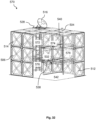
- Fig. 1 illustrates a partially exploded view of a first sectional panel tank 100 with an external foundation 130.
- the first sectional panel tank 100 has a cubic dimension with a bottom 102, a roof or cover 104 and four side walls, including a front wall 106, a rear wall 108 (not shown), a left wall 110 (not shown) and a right wall 112. Therefore, twelve (12) edges 138 of the sectional panel tank 100 are formed for the first sectional panel tank 100.
- the bottom 102, the cover 104 and the side walls 106, 108, 110, 112 are assembled by multiple unit panels 114 joined together.
- the first sectional panel tank 100 further comprises an access hole or manhole 116 at a corner of the cover 104, a ladder 118 fixed to the right wall 112, a drainage hole 120 connected to a drainage tube 122, an inlet 124 and an outlet 126 at an upper part and a lower part of the front wall 106 respectively.
- the inlet 124 and the outlet 126 are typically furthest apart from each other for proper circulation of liquid to avoid stagnation.
- a top end 128 of the ladder 118 is located inn vicinity of the access hole 116.
- the external foundation 130 is laid on the ground for supporting the first sectional tank 100; and an external framework 132 connected to the multiple unit panels for upholding structural integrity of the first sectional panel tank 100.
- the first sectional panel tank 100 is used for storing a liquid 134 (not shown) inside a space defined by the bottom 102, the cover 104 and the four side walls 106, 108, 110, 112.
- the liquid 134 is filled into and discharged out of the space through the inlet 124 and the outlet 126.
- the liquid 134 is removed from the space through the drainage tube 122 and the drainage hole 120 in a quicker manner.
- the outlet 126 is usually higher than the drainage hole 120 so that any sediments cannot enter into the supply line. Drainage hole 120 is usually the lowest point of the first sectional panel tank 100, where sedimentation can be discharged.
- Fig. 2 illustrates a partially exploded view of a variant 150 of the first sectional panel tank 100 in Fig. 1 .
- the variant 150 has a similar structure with the first sectional panel tank 100 and thus features of the variant 150 herein are made references to the first sectional panel tank 100 illustrated in Fig. 1 .
- the variant 150 has a second ladder 152 inside the variant 150 for easily getting access into the bottom 102 of the variant 150 via the access hole 116.
- the variant 150 has a partition 154 for partitioning the variant 150 into two small tanks, i.e. a first tank 156 enclosed by the front wall 106, the rear wall 108, the left wall 110 and the partition 154; and a second tank 158 enclosed by the front wall 106, the rear wall 108, the right wall 112 and the partition 154.
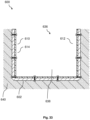
- Fig. 3 illustrates a partially exploded view of the first sectional panel tank 100 without an external foundation 130. All features of the first sectional panel tank 100 are identical to those in Fig. 1 , except that the bottom 102 is not needed.
- a compacted and flat soil plate (not shown) is prepared from the ground; and then a piece of lining 136 is spread on the compacted and flat soil plate.
- the first sectional panel tank 100 is directly built on the lining 136 by erecting the side walls 106, 108, 110, 112 and the joining the cover 104 with the side walls 106, 108, 110, 112.
- This first sectional panel tank 100 in Fig. 3 is particularly used for oil storage and chemical waste treatment. It is also understood that the first sectional panel tank 100 herein can also be suitable for potable water.
- Fig. 4 illustrate a partially exploded view of the variant 170 of the first sectional panel tank in Fig. 3 .
- the variant 170 has a similar structure with the first sectional panel tank 100 and thus features of the variant 150 herein are made references to the first sectional panel tank 100 illustrated in Fig. 3 .
- the variant 170 has a second ladder 172 inside the variant 170 for easily getting access into the lining 136 of the variant 170 via the access hole 116.
- the variant 170 has a partition 174 for partitioning the variant 170 into two small tanks, i.e. a first tank 176 enclosed by the front wall 106, the rear wall 108, the left wall 110 and the partition 174; and a second tank 178 enclosed by the front wall 106, the rear wall 108, the right wall 112 and the partition 174.
- Fig. 5 illustrates an isometric view ( Fig. 5(a) ) and a cross-sectional view ( Fig. 5(b) ) of a first unit panel 200 from an internal point of view
- Fig. 6 illustrates an isometric view ( Fig. 6(a) ) and a cross-sectional view ( Fig. 6(b) ) of the first unit panel in Fig. 5 from an external point of view.
- the first unit panel 200 comprises a first structural panel 202, a first lining sheet 204 and a first extension 208.
- the first extension 208 further comprises four flanges folded at substantially 90 degrees at four peripheral edges of the first unit panel 200 respectively, i.e.
- the first structural panel 202 thus extends between the four flanges 210, 214, 218, 222.
- the first structural panel 202 is made of stainless steel that is impermeable, corrosion resistive, and mechanically robust for resisting pressure of the fluid 134.
- the four flanges 210, 214, 218, 222 are formed by folding the four edges 212, 216, 220, 224 respectively at substantially 90 degrees.
- the four flanges 210, 214, 218, 222 are substantially vertically positioned to the four edges 212, 216, 220, 224 respectively.
- the first structural panel 202 has a size less than four square meters and a thickness of around 2 millimetres (mm); while the first lining sheet 204 also has a thickness of around 2 millimetres (mm). Therefore, the first unit panel 200 has a total thickness of around 4 millimetres (mm).
- the first lining sheet 204 has two flat sides, i.e. a first side 242 and a second side 244.
- the first side 242 is joined to an inner surface 226 of the first structural panel 202 for forming the first unit panel 200 by a thermoforming method.
- the first lining sheet 204 completely covers the inner surface 226, including the first structural panel 202 and the first extension 208.
- the first lining sheet 204 is made of a thermoplastic material such as PE, PP, PVDF, ECTFE. Since in direct contact with the liquid 134, the first lining sheet 204 is required to be water-proof and corrosion resistant to water and almost all chemical solutions.
- the first unit panel 200 comprises a first embossment 230 on the first structural panel 202 for further strengthening mechanical properties of the first structural panel 202.
- Fig. 7 illustrates a cross-sectional view of a variant 2000 of the first unit panel 200 in Fig. 5(b) .
- the variant 2000 has a similar structure with the first unit panel 200 and thus features of the variant 2000 herein are made references to the first unit panel 200 illustrated in Fig. 5(b) .
- the first lining sheet 204 also covers the external surface 228 of the first structural panel 202. In other words, the first lining sheet 204 encapsulates the first structural panel 202 and the first extension 208 completely.
- the variant 2000 is particularly suited for partition panels as seen in Fig 2 and Fig 4 .
- Fig. 8 illustrates a cross-sectional view of another variant 2100 of the first unit panel 200 in Fig. 5(b) .
- the variant 2100 has a similar structure with the first unit panel 200 and thus features of the variant 2100 herein are made references to the first unit panel 200 illustrated in Fig. 5(b) .
- the variant 2100 has a first thermal insulation layer 206 formed on an external surface 228 of the first structural unit panel 202 for reducing temperature fluctuation of the fluid 134.
- the first thermal insulation layer 206 is made of fiberglass that is light in weight and also hydrophobic to water. It is noted that the first thermal insulation layer 206 covers a central portion of the first unit panel 200, including the first embossment 230.
- Fig. 9 illustrate a cross-sectional view of another variant 2200 of the first unit panel 200 in Fig. 5(b) .
- the variant 2200 has a similar structure with the variant 2100 and thus features of the variant 2200 herein are made references to the variant 2100 illustrated in Fig. 8 .
- the first thermal insulation layer 206 is sandwiched between the first structural panel 202 and the first lining sheet 204.
- the first thermal insulation layer 206 is attached between the inner surface 226 of the first structural panel 202 and the first side 242 of the first lining sheet 204. Therefore, the first thermal insulation layer 206 for the variant 2200 is known as an inner insulation layer.
- the first thermal insulation layer 206 also covers the first structural panel 202 completely, but does not extend to cover the first extension 208.
- Fig. 10 illustrate a cross-sectional view of another variant 2300 of the first unit panel 200 in Fig. 5(b) .
- the variant 2300 has a similar structure with the variant 2200 and thus features of the variant 2300 herein are made references to the variant 2200 illustrated in Fig. 9 .
- the first thermal insulation layer 206 is sandwiched between the first structural panel 202 and the first lining sheet 204; but the first thermal insulation layer 206 is attached to the external surface 228 of the first structural panel 202 due to the complete encapsulation of the first structural panel 202 by the first lining sheet 204 similar to the variant 2000 in Fig. 7 . Therefore, the first thermal insulation layer 206 for a variant 2300 is known as an external insulation layer.
- the first lining sheet 204 is in direct contact with the inner surface 226 of the first structural panel 202.
- Fig. 11 illustrate a cross-sectional view of a modification 2400 to the variant 2100 in Fig. 8 incorporated with studs 240.
- the studs 240 are either attached to the first side 242 of the first lining sheet 204 or attached to the inner surface 226 of the first structural panel 202.
- the first side 242 is assembled towards the first structural panel 202; and the second side 244 is in direct contact with water stored in the first unit panel tank 100.
- a continuous gap 246 is thus formed between the first structural panel 202 and the first side 242 of the first lining sheet 204.
- a porous filler 248 (such as aerogel) is filled inside the gap 246 as the first thermal insulation layer 206 for providing thermal insulation.
- the thermal insulation ensures that the first sectional panel tank 100 is still workable in high latitude countries in a cold winter or for special applications (such as spa).
- the porous filler 248 may also provide cushion to external shocks.
- the cushion function ensures that the first lining sheet 204 is tightly pushed against the first structural panel 202 under a pressure of the water stored inside the first sectional panel tank 100.
- the studs 240 do not exist at the flanges 210, 214, 218, 222 for tightly and reliably joined the first side 242 and the first structural panel 202.
- Fig. 13 illustrates a cross-sectional view of another modification 2600 to the first unit panel 200 in Fig. 5(b) with an adhesive layer 2610 when the first lining sheet 204 has a fabric backed liner (FBL).
- the adhesive layer 2610 adheres the fabric backed liner (FBL) to the inner surface 226 of the first structural panel 202.
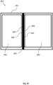
- Fig. 14(a) illustrates a cross-sectional view of the first unit panel 200 at a top side and the second unit panel 250 at a bottom side vertically joined together at a joint 290.
- the unit panels 200, 250 are joined for forming the side walls 106, 108, 110, 112 of the first sectional panel tank 100 in Fig. 1 to Fig. 4 .
- the first unit panel 200 and the second unit panel 250 are joined at the joint 290 between the first rear flange 214 and the second front flange 260 by a thermoplastic welding method.
- a fastener 235 such as a screw (Nut and Bolt) also binds the first rear flange 214 and the second front flange 260 at the joint 209.
- Fig. 15(a) illustrate a cross-sectional view of two identical variants 2100 in Fig. 8 vertically joined together at the joint 290, i.e. the variant 2100 at a top side and another variant 2150 at a bottom side, each of which has all the features of the variant 2100 in Fig. 8 .
- the variants2100, 2150 are joined for forming the side walls 106, 108, 110, 112 of the first sectional panel tank 100 in Fig. 1 to Fig. 4 .
- the variants2100 and 2150 are joined at the joint 290 between the first rear flange 214 and the second front flange 260 by a thermoplastic welding method.
- the fastener 235 is also used to bind the first rear flange 214 and the second front flange 260 at the joint 290.
- the second variant 2150 has a second thermal insulation layer 256.
- Fig. 15(b) illustrates an enlarged cross-sectional view of the joint 290. It is also clearly seen that the first rear flange 214 and the second front flange 260 are joined together at the joint 290 by thermoplastic welding which introduces the jointer 294 for sealing the seam 292. Similar to the Fig. 14(b) , no gasket is needed for preventing any leakage from the joint 290. In addition, the first thermal insulation layer 206, the first embossment 230, the second thermal insulation layer 256 and the second embossment 280 terminate outside the joint 290.
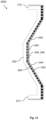
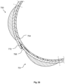
- Fig. 16 illustrates (a) an isometric view and (b) a cross-sectional view of a curved unit panel 3000 from an external point of view.
- the curved unit panels 3000 has a curved structural panel 3002 which further has an extension 3020.
- the extension 3020 has a front flange 3022 folded at a front edge 3012, a rear flange 3024 folded at a rear edge 3014, a left flange 3026 folded at a left edge 3016 and a right flange 3028 folded at a right edge 3018.
- the curved unit panel 3000 has a curved lining sheet 3004 encapsulating an inner surface 3008 of the curved structural panel 3002, including the extension 3020 (i.e. the flanges 3022, 3024, 3026, 3028).
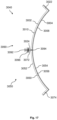
- Fig. 17 illustrates a cross-sectional view of two identical curved unit panels joined together, i.e. a first curved unit panel 3040 and a second curved unit panel 3050, which have the same structures to the curved unit panel 3000 in Fig. 16 .
- the second curved unit panel 3050 has a second structural panel 3052 which further has a second extension 3070.
- the second extension 3070 has a second front flange 3072 folded at a second front edge 3062, a second rear flange 3074 folded at a second rear edge 3064, a second left flange 3076 (not shown) folded at a second left edge 3066 (not shown) and a second right flange 3078 (not shown) folded at a second right edge 3068 (not shown).
- the second curved unit panel 3050 has a second lining sheet 3054. Similar to the joined unit panels 200, 250 in Fig. 14 , the first and the second curved unit panels 3040, 3050 are joined together at a joint 3090. In detail, the curved lining sheet 3004 and the second lining sheet 3054 are pressed in direct contact at the joint 3090.
- the joint 3090 comprises a seam 3092 even if the curved lining sheet 3004 and the second lining sheet 3054 are closely pressed against each other.
- the thermoplastic welding introduces a jointer 3094 for joining the curved lining sheet 3004 and the second lining sheet 3054.
- a fastener 3096 (such as a screw) is also used to bind the rear flange 3024 and the second front edge 3062 at the joint 3009. In contrast to known techniques, no gasket is needed for preventing any leakage from the joint 3090.
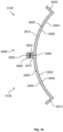
- Fig. 18 illustrates a cross-sectional view of two identical variants of the curved unit panels joined together; i.e. a first variant 3100 and a second variant 3150.
- the variants 3100, 3150 have a similar structure with the curved unit panels 3040, 3050 and thus features of the variants 3100, 3150 herein are made references to the curved unit panels 3040, 3050 illustrated in Fig. 17 .
- the curved lining sheet 3004 encapsulates the curved structural panel 3002 entirely, including the inner surface 3008 and an external surface 3010 of the curved structural panel 3002.
- the second lining sheet 3054 encapsulates the second structural panel 3052 entirely, including a second inner surface 3058 and a second external surface 3060 of the second structural panel 3052.
- the embodiment in Fig. 18 is suitable for the cases where a smaller cylindrical sectional panel tank sits within a bigger cylindrical sectional tank, which contain different substances (such as different liquids) respectively.
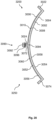
- Fig. 19 illustrates a cross-sectional view of another two identical variants of the curved unit panels joined together, i.e. a first variant 3200 and a second variant 3250.
- the variants 3200, 3250 have a similar structure with the curved unit panels 3040, 3050 and thus features of the variants 3200, 3250 herein are made references to the curved unit panels 3040, 3050 illustrated in Fig. 17 .
- the variants 3200, 3250 Different from the curved unit panels 3000, 3050, the variants 3200, 3250 have a curved thermal insulation layer 3006 and a second thermal insulation layer 3056 respectively.
- the curved thermal insulation layer 3006 is sandwiched between the curved lining sheet 3004 and the inner surface 3008; while the second thermal insulation layer 3056 is also sandwiched between the second lining sheet 3054 and the second inner surface 3058.
- Fig. 20 illustrates a cross-sectional view of another two identical variants of the curved unit panels joined together, i.e. the first variant 3200 and the second variant 3250.
- the variants 3200, 3250 have a similar structure with the variants 3100, 3150 and thus features of the variant 3200, 3250 herein are made references to the curved unit panels 3100, 3150 illustrated in Fig. 19 .
- the curved thermal insulation layer 3006 is sandwiched between the curved lining sheet 3004 and the external surface 3010; while the second thermal insulation layer 3056 is also sandwiched between the second lining sheet 3054 and the second externals surface 3060.
- Fig. 21 illustrates a cross-sectional view of two identical modifications of the curved unit panels joined together, i.e. a first modification 3300 and a second modification 3350.
- the modifications 3300, 3350 have a similar structure with the curved unit panels 3040, 3050 and thus features of the modification 3300, 3350 herein are made references to the curved unit panels 3040, 3050 illustrated in Fig. 17 .
- the first modification 3300 has first studs 3310 sandwiched between the inner surface 3008 and the curved lining sheet 3004 for forming a first gap 3320; while the second modification 3350 has second studs 3360 sandwiched between the second inner surface 3508 and the second lining sheet 3504 for forming a second gap 3370.
- a first filler 3330 and a second filler 3380 are filled into the first gap 3320 and the second gap 3370, respectively. Similar to the filler 248 in Fig. 11 and Fig. 12 , the fillers 3330, 3380 may act as the thermal insulation layers 3306, 3356 for providing thermal insulation. Alternatively, the fillers 3330, 3380 may provide cushion to external shocks. The first filler 3330 and the second filler 3380 may be the same or different.
- Fig. 22 illustrates a cross-sectional view of another two identical modifications of the curved unit panels joined together, i.e. a first modification 3400 and a second modification 3450.
- the modifications 3300, 3350 have a similar structure with the curved unit panels 3040, 3050 and thus features of the modification 3300, 3350 herein are made references to the curved unit panels 3040, 3050 illustrated in Fig. 17 .
- the modifications 3300, 3350 have a first adhesive layer 3340 and a second adhesive layer 3390, respectively when the lining sheets 3304, 3354 have fabric backed liner (FBL).
- the adhesive layers 3340, 3390 adhere the fabric backed liner (FBL) to the inner surfaces 3308, 3358 respectively.
- Fig. 23 illustrates a cross-sectional view of three unit panels of Fig. 5(b) joined together, i.e. the first unit panel 200, the second unit panel 250 and a third unit panel 2700 vertically joined at the joint 290 and a joint 2710 in sequence for forming the right wall 112 and the front wall 106, respectively. Similar to the fastener 235, another fastener 2730 is used to further secure the joint 2710.
- Fig. 24 illustrates a top planar view of multiple unit panels of Fig. 5(b) joined together for forming the variant 150 of the first sectional unit panel 100.
- the first unit panels 200 and the second unit panels 250 are joined for forming the front wall 106, the rear wall 108, the left wall 110, the right wall 112 and partition 154, respectively.
- Fig. 25 illustrates a cross-sectional view of the first unit panel 200 of Fig. 5(b) and a planar unit panel 2800 orthogonally joined together.
- the planar unit panel 2800 has a planar structural panel 2810 and a planar lining sheet 2820 formed together.
- the first unit panel 200 and the planar unit panel 2800 are joined at a joint 2840 with the first rear flange 214 and a left end 2830 of the planar unit panel 2800.
- a fastener 2850 is used to further secure the joint 2840.
- Fig. 26 illustrates a cross-sectional view of another unit panel, i.e. a third unit panel 300.
- the third unit panel 300 comprises a third structural panel 302, a third thermal insulation layer 306, and a third extension 308.
- the third extension 308 further comprises a third front flange 310 folded at a third front edge 312, a third rear flange 314 folded at a third rear edge 316, a third left flange 318 (not shown) folded at a third left edge 320 (not shown), and a third right flange 322 (not shown) folded at a third right edge 324 (not shown).
- the third unit panel 300 does not have a lining sheet similar to the first lining sheet 204 or the second lining sheet 254.
- a fourth unit panel 350 is provided for being joined with the third unit panel 300.
- the fourth panel 350 is identical to the third unit panel 300 as described in Fig. 26 .
- the fourth unit panel 300 comprises a fourth structural panel 352, a fourth thermal insulation layer 356, and a fourth extension 358.
- the fourth extension 358 further comprises a fourth front flange 360 folded at a fourth front edge 362, a fourth rear flange 364 folded at a fourth rear edge 366, a fourth left flange 368 folded at a fourth left edge 370, and a fourth right flange 372 folded at a fourth right edge 374.
- Fig. 27(a) illustrates a cross-sectional view of two unit panels 300, 350 vertically joined for forming the side wall 106, 108, 110, 112 of the first sectional panel tank 100 in Fig.1 to Fig. 4 .
- the third unit panel 300 and the fourth unit panel 350 are joined at a joint 390 between the third rear flange 314 and the fourth front flange 360 by a metal welding method.
- the joint 390 comprises a seam 392 even if the third rear flange 314 and the fourth front flange 360 are closely pressed against each other.
- the metal welding introduces a jointer 394 for joining the third rear flange 314 and the fourth front flange 360.
- a single and continuous lining 340 instead of the two lining sheets 204, 254 joined together, is used to cover an inner surface 326 of the third unit panel 300, the inner surface 376 of the fourth unit panel 350 and the joint 390 for preventing any leakage.
- the unit panels 300, 350 are also horizontally joined together for forming the bottom 102 and/or the cover 104 of the first sectional panel tank 100.
- an adhesive 330 is applied to the third structural panel 302 and the fourth structural panel 352 before the lining 340 is applied for further fixing the lining in place.
- Fig. 27(b) illustrates an enlarged cross-sectional view of a joint 390.
- the third rear flange 314 and the fourth front flange 360 are pressed against each other without a lining sheet or a known gasket in-between.
- the joint 390 comprises a seam 392 that is sealed by a jointer 394 by the solvent welding method.
- the lining 340 is then joined onto the joint 390 from the inner surfaces 326, 376 for further preventing any leakage from the joint 390.
- Fig. 28 illustrates an enlarged cross-sectional view of the lining sheet 204, 254.
- the lining sheet 204, 254 comprises a first layer 296 attached on the inner surfaces 226, 276 of the unit panels 200, 250; and a second layer 298 attached on the first layer 296.
- the second layer 298 is in contact with the liquid 134 stored inside the first sectional panel tank 100.
- the first layer 296 and the second layer 298 has a first thickness 297 and a second thickness 299 of 200 micrometres and 1.8 millimetres respectively.
- the first layer 296 and the second layer 298 are both made of a same thermoplastic material such as PE, PP, PVDF, ECTFE for easy and reliable attachment.
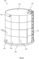
- Fig. 33 illustrates a cross-sectional view of a third sectional panel tank 600.
- the third sectional panel tank 600 shares some features of the first sectional panel tank 100, basically comprising a bottom 602, a cover 604 (not shown), a front wall 606 (not shown), a rear wall 608 (not shown), a left wall 610 and a right wall 612 that are built up by multiple unit panels 614.
- the sectional panel tank 600 is not an independent device that stands by itself, the bottom 602 and the four side walls 606, 608, 610, 612 are surrounded and supported by a facility 636.
- the facility 636 comprises a hole 638 dug in a ground 640 of the earth.
- Fig. 37 illustrates a perspective view and a cross-sectional view of the curved unit panel 714.
- the curved unit panel 714 further comprises a structural panel 752 and a thermal insulation layer 756 and an extension 758.
- the extension 758 comprises four margins at four peripheral edges of the curved unit panel 714 respectively, i.e. a front margin 760 (not shown) at a front edge 762, a rear margin 764 (not shown) at a rear edge 766, a left margin 768 at a left edge 770, and a right margin 772 at a right edge 774.
- the four margins 760, 764, 768, 772 are not folded at an angle (such as 90 degrees) to the edges 762, 768, 770, 774 respectively.
- the structural panel 752 thus extends between the four margins 760, 764, 768, 772.
- Fig. 38 illustrates a cross-sectional view of two curved unit panels 714 joining together, i.e. a fifth unit panel 750 and a sixth unit panel 751.
- the right margin 772 of the fifth unit panel 750 and the left margin 768 of the sixth unit panel 752 are overlapped and joined together.
- a single and continuous lining 754 is then joined onto inner surfaces of the fifth unit panel 750 and the sixth unit panel 751.
- Fig. 39 illustrates a cross-sectional view of a partition tank 800 based on a sectional panel tank 801 described above, i.e. anyone of the sectional panel tanks 100, 500, 600, 700.
- the partition tank 800 is completely separated by a partition part 802 into a first sub-tank 804 and a second sub-tank 806.
- the first sub-tank 804 and the second sub-tank contain a first fluid 808 (not shown) and a second fluid 810 (not shown) respectively.
- the first fluid 808 and the second fluid 810 do not communicate through the partition part 802.
- the partition part 802 comprises a first side 812 and a second side 814 in contact with the first fluid 808 and the second fluid 810 respectively.
- the partition part 802 is firstly assembled from the second side 814 by joining the first unit panel 200 and the second unit panel 250 together at the joint 290 between the first lining sheet 204 and the second lining sheet 254.
- the first and second unit panels 200, 250 are then further joined at the joint 290 from the first side 812 of the partition part 800.
- the partition part 800 finally further comprises an additional lining sheet 816 covering the first side 812, particular the joint 290. Therefore, the joint 290 is protected from the first side 812 by the additional lining sheet 816 and from the second side 814 by the first and second lining sheets 204, 254.
- the partition part 802 is protected from the first fluid 808 by the pre-formed lining sheets 204, 254 at the first side 812; and from the second fluid 810 by the post-formed additional lining sheet 816 after the partition part 800 is assembled from the first side 812.
- Fig. 40 illustrates a cross-sectional view of another partition tank 850 using the third unit panels 300 and the fourth unit panel 350 described in Fig. 27 .
- a partition part 852 is assembled for completely separating the partition tank 850 into a first sub-tank 854 and a second sub-tank 856 for containing a first fluid 858 and a second fluid 860 respectively.
- the partition part 852 is assembled by joining the third unit panel 300 and the fourth unit panel 350 at the joint 390 from both a first side 862 and a second side 864 of the partition part 852.
- Fig. 41 illustrates a cross-sectional view of a vacuum forming process S10 for producing a prefabricated unit panel 900, including but not limited to any unit panel describe above.
- An exemplary vacuum forming process S10 is shown process the prefabricated unit panel 900.
- a structural panel 910 is placed into a vacuum chamber 950 before the vacuum forming process S10.
- the vacuum forming process S10 has a first step S100 (shown in Fig. 41(a) ) of aligning a lining sheet 920 over the structural panel 910; a second step S200 (shown in Fig. 41(b) ) of heating the lining sheet 920 to be pliable for deformation; and a third step S300 (shown in Fig.
- the negative pressure may be generated by any known apparatus or method, such as a vacuum pump which pumps air from the vacuum chamber 950 to an outside environment.
- a driving plate 960 is placed inside the vacuum chamber 950 for fixing and moving the structural panel 910 upwardly towards the lining sheet 920.
- the driving plate 960 has a plurality of orifices 970 for air to go through the driving plate 960. As shown by straight arrows 980 in Fig.
- hot air goes upwardly through the orifices 970 to reach the lining sheet 920 for heating the lining sheet 920 to a predetermined temperature.
- the hot air is spread evenly through the orifices 970 for heating the lining sheet 920 more homogeneously.
- the air inside the vacuuming chamber 950 is extracted outside for forming the negative pressure required for the vacuuming forming process.
- the third step S300 further has a first procedure S310 of moving the structural panel 910 upwardly towards the lining sheet 920; a second procedure S320 of vacuum forming the lining sheet 920 to the structural panel 910 for transferring contours of the inner surface 912 of the structural panel 910 to the lining sheet 920; and a third procedure S330 of cooling the lining sheet 920 for crystalizing the contours to the lining sheet 920 and thus joining the structural panel 910 and the lining sheet 920 together.
- the term "about”, in the context of concentrations of components of the formulations, typically means +/- 5% of the stated value, more typically +/- 4% of the stated value, more typically +/- 3% of the stated value, more typically, +/- 2% of the stated value, even more typically +/- 1% of the stated value, and even more typically +/- 0.5% of the stated value.
- range format may be disclosed in a range format.
- the description in range format is merely for convenience and brevity and should not be construed as an inflexible limitation on the scope of the disclosed ranges. Accordingly, the description of a range should be considered to have specifically disclosed all the possible sub-ranges as well as individual numerical values within that range.
- description of a range such as from 1 to 6 should be considered to have specifically disclosed sub-ranges such as from 1 to 3, from 1 to 4, from 1 to 5, from 2 to 4, from 2 to 6, from 3 to 6 etc., as well as individual numbers within that range, for example, 1, 2, 3, 4, 5, and 6. This applies regardless of the breadth of the range.
Landscapes
- Engineering & Computer Science (AREA)
- Mechanical Engineering (AREA)
- Filling Or Discharging Of Gas Storage Vessels (AREA)
Claims (9)
- Réservoir à panneaux sectionnels (100, 150, 170), comprenant :au moins une paroi latérale (106) pour joindre d'autres parois latérales lors de la formation du réservoir à panneaux sectionnels ;dans lequel l'au moins une paroi latérale comprend :➢ un premier panneau d'unité (200) ayant une première extension à son bord pour supporter le premier panneau d'unité ;➢ au moins une doublure (204) fixée sur un côté interne du premier panneau d'unité pour empêcher la corrosion du premier panneau d'unité ;➢ un deuxième panneau d'unité (250) ayant une deuxième extension à son bord ; et➢ une jointure (294) appliquée au joint sur des côtés internes du premier panneau d'unité et du deuxième panneau d'unité du réservoir à panneaux sectionnels pour combler un espace entre les panneaux d'unité voisins de sorte que les côtés ou surfaces internes du premier panneau d'unité et du deuxième panneau d'unité forment une surface continue, qui est imperméable aux solides, aux liquides ou aux gaz, dans lequel le premier panneau d'unité et le deuxième panneau d'unité sont joints de manière contiguë à la première extension et à la deuxième extension par au moins une fixation.
- Réservoir à panneaux sectionnels selon la revendication 1, dans lequel l'au moins une doublure (204) comprend un matériau thermoplastique.
- Réservoir à panneaux sectionnels selon l'une des revendications précédentes 1 ou 2, dans lequel
l'au moins une doublure (204) comprend une première couche d'une première couleur et une deuxième couche d'une deuxième couleur. - Réservoir à panneaux sectionnels selon l'une des revendications précédentes, comprenant en outre➢ un fond (102) ayant une extension de fond, le fond et l'au moins une paroi latérale étant directement joints à l'extension de fond ; et➢ une jointure de fond appliquée à un joint de fond entre l'extension de fond et l'au moins une paroi latérale.
- Réservoir à panneaux sectionnels selon l'une des revendications précédentes, comprenant en outre
un moyen de fixation pour fixer la première extension et la deuxième extension ensemble. - Réservoir à panneaux sectionnels selon la revendication 5, dans lequel le premier moyen de fixation et le deuxième moyen de fixation comprennent un premier revêtement et un deuxième revêtement, respectivement,
le premier revêtement et le deuxième revêtement sont compatibles avec la doublure pour éviter une fuite. - Procédé de fabrication d'une paroi latérale pour un réservoir à panneaux sectionnels, comprenant le fait de➢ fournir un premier panneau d'unité (200) ayant une extension à son bord en tant que première extension et ayant au moins une doublure (204) fixée sur un côté interne du premier panneau d'unité ;➢ fournir un deuxième panneau d'unité (250) ayant une extension à son bord en tant que deuxième extension ;➢ joindre directement le premier panneau d'unité et le deuxième panneau d'unité par l'intermédiaire d'un moyen de fixation à la première extension et à la deuxième extension ; et➢ appliquer une jointure (294) à un joint entre la première extension et la deuxième extension sur des côtés internes du premier panneau d'unité et du deuxième panneau d'unité.
- Procédé selon la revendication 7, dans lequel
la fixation de la doublure (204) comprend un processus de thermoformage. - Procédé selon la revendication 8, dans lequel
l'application de la jointure (294) par un processus de soudage thermoplastique.
Priority Applications (1)
| Application Number | Priority Date | Filing Date | Title |
|---|---|---|---|
| EP24198705.6A EP4480853A3 (fr) | 2019-11-21 | 2020-11-20 | Réservoir à panneaux en sections |
Applications Claiming Priority (6)
| Application Number | Priority Date | Filing Date | Title |
|---|---|---|---|
| SG10201910976UA SG10201910976UA (en) | 2019-11-21 | 2019-11-21 | Sectional Panel Tank |
| MYPI2019007789A MY203956A (en) | 2019-11-21 | 2019-12-26 | Sectional panel tank |
| CN201911414932.XA CN112824239B (zh) | 2019-11-21 | 2019-12-31 | 拼装板式储箱 |
| CN201922481683.8U CN211845325U (zh) | 2019-11-21 | 2019-12-31 | 一种拼装板式储箱及用于制造该拼装板式储箱的预制单元板 |
| KR1020200011070A KR102392803B1 (ko) | 2019-11-21 | 2020-01-30 | 조립식 패널 탱크 |
| PCT/SG2020/050677 WO2021101448A1 (fr) | 2019-11-21 | 2020-11-20 | Réservoir à panneaux en sections |
Related Child Applications (2)
| Application Number | Title | Priority Date | Filing Date |
|---|---|---|---|
| EP24198705.6A Division-Into EP4480853A3 (fr) | 2019-11-21 | 2020-11-20 | Réservoir à panneaux en sections |
| EP24198705.6A Division EP4480853A3 (fr) | 2019-11-21 | 2020-11-20 | Réservoir à panneaux en sections |
Publications (3)
| Publication Number | Publication Date |
|---|---|
| EP4061745A1 EP4061745A1 (fr) | 2022-09-28 |
| EP4061745A4 EP4061745A4 (fr) | 2023-10-25 |
| EP4061745B1 true EP4061745B1 (fr) | 2025-07-02 |
Family
ID=75981749
Family Applications (2)
| Application Number | Title | Priority Date | Filing Date |
|---|---|---|---|
| EP24198705.6A Pending EP4480853A3 (fr) | 2019-11-21 | 2020-11-20 | Réservoir à panneaux en sections |
| EP20888851.1A Active EP4061745B1 (fr) | 2019-11-21 | 2020-11-20 | Réservoir à panneaux en sections, processus de fabrication d'une paroi latérale pour un réservoir à panneaux en sections |
Family Applications Before (1)
| Application Number | Title | Priority Date | Filing Date |
|---|---|---|---|
| EP24198705.6A Pending EP4480853A3 (fr) | 2019-11-21 | 2020-11-20 | Réservoir à panneaux en sections |
Country Status (4)
| Country | Link |
|---|---|
| US (1) | US11926471B2 (fr) |
| EP (2) | EP4480853A3 (fr) |
| JP (1) | JP7574288B2 (fr) |
| WO (1) | WO2021101448A1 (fr) |
Families Citing this family (2)
| Publication number | Priority date | Publication date | Assignee | Title |
|---|---|---|---|---|
| FR3089891B1 (fr) * | 2018-12-18 | 2020-11-27 | Stelia Aerospace | Planche de bord modulable |
| US20230123191A1 (en) * | 2021-10-16 | 2023-04-20 | Jean-Jacques Grimaud | Storage and Transport of Hygroscopic Products |
Family Cites Families (50)
| Publication number | Priority date | Publication date | Assignee | Title |
|---|---|---|---|---|
| US1427166A (en) * | 1920-10-14 | 1922-08-29 | Wearever Tank & Paint Co | Tank or storage receptacle |
| US1943191A (en) * | 1933-02-16 | 1934-01-09 | Parkersburg Rig & Reel Co | Fabricated tank |
| US3410441A (en) * | 1966-06-29 | 1968-11-12 | Jeff S. Rhyne | Container |
| FR1544078A (fr) | 1966-08-26 | Réservoir pour liquides, conçu en particulier comme réservoir d'huile | ||
| JPS4937504Y1 (fr) * | 1970-01-26 | 1974-10-14 | ||
| USRE27330E (en) * | 1970-06-03 | 1972-04-11 | Thermally insulated tank structure | |
| JPS4877351U (fr) * | 1971-12-28 | 1973-09-25 | ||
| DE2321953A1 (de) | 1973-05-02 | 1974-11-14 | Berger Wolfgang Dipl Ing | Tuebbing-tank fuer die lagerung von fluessigkeiten |
| US4188759A (en) * | 1974-07-22 | 1980-02-19 | Trioliet-Mullos Silo Nederland B.V. | Sheet for constructing the wall of a substantially cylindrical silo; as well as substantially cylindrical silo |
| JPS5929510B2 (ja) * | 1976-01-16 | 1984-07-20 | 積水化学工業株式会社 | 液槽の防食内張工法 |
| AT350762B (de) | 1977-06-24 | 1979-06-25 | Doubrava Kg | Grossraumsilo in segmentbauweise |
| US4244486A (en) * | 1979-05-11 | 1981-01-13 | Ewald Jr Herbert J | Tank |
| DE2926253A1 (de) * | 1979-06-29 | 1981-01-08 | Adolf Lesk | Aus segmenten bzw. einzelteilen zusammengefuegte silos bzw. behaelter sowie verfahren zum zusammenfuegen derselben |
| US4376360A (en) * | 1981-01-26 | 1983-03-15 | Hanson Silo Company | Access door assembly for a silo |
| JPS58110729A (ja) * | 1981-12-25 | 1983-07-01 | 株式会社ブリヂストン | 水槽用バルブボツクス |
| JPS60166625U (ja) * | 1984-04-16 | 1985-11-05 | 三菱自動車工業株式会社 | 燃料タンク |
| JPS6237470A (ja) * | 1985-08-12 | 1987-02-18 | 川重工事株式会社 | タンクの建設方法 |
| DE3542709A1 (de) * | 1985-12-03 | 1987-06-04 | Jansens & Dieperink Bv | Verfahren zum herstellen von grossraumbehaeltern sowie dazu verwendbare einzelsegmente und ausrichtewerkzeug zum ausrichten derselben |
| JPH0311697U (fr) * | 1989-06-20 | 1991-02-05 | ||
| US5052569A (en) * | 1991-02-19 | 1991-10-01 | Cooper Clinton T | Safety enclosure for storing containers of hazardous material |
| US5449081A (en) * | 1993-05-21 | 1995-09-12 | Stoughton Composites, Inc. | Modular insulated intermodal container construction |
| JP3197149B2 (ja) * | 1994-04-21 | 2001-08-13 | 日進ケミカル工業株式会社 | 耐薬品性シートライニングタンク |
| US5741042A (en) * | 1995-03-23 | 1998-04-21 | Stoughton Composites, Inc. | Intermodal container including double lap shear joints |
| US5688086A (en) * | 1996-02-16 | 1997-11-18 | Aluminum Company Of America | Standard corner fittings for aluminum container frames |
| JPH1135090A (ja) * | 1997-05-23 | 1999-02-09 | Mitsubishi Plastics Ind Ltd | 酸性水用タンク |
| JP2000213073A (ja) * | 1999-01-22 | 2000-08-02 | Hitachi Chem Co Ltd | パネル組立式蓄熱槽 |
| US6244063B1 (en) * | 1999-10-12 | 2001-06-12 | Manitowoc Foodservice Group Inc. | Refrigeration wall system |
| JP2001130692A (ja) | 1999-11-10 | 2001-05-15 | Sayama Seisakusho:Kk | 貯水槽 |
| JP2001173033A (ja) * | 1999-12-17 | 2001-06-26 | Sayama Seisakusho:Kk | 貯水槽 |
| US20040107823A1 (en) * | 2002-06-07 | 2004-06-10 | Kiley Matthew P. | Explosion resistant cargo container |
| KR200306519Y1 (ko) * | 2002-12-20 | 2003-03-11 | 영성산업 주식회사 | 내,외부 혼합식 보강구조를 갖는 조립식 물탱크 |
| JP2004224422A (ja) * | 2003-01-27 | 2004-08-12 | Nippon Dekishii:Kk | 紙製シームレスカップ及びその製造方法 |
| US20050229501A1 (en) * | 2004-04-20 | 2005-10-20 | Grossman Rodney B | Granular material storage container and associated method |
| KR200363822Y1 (ko) * | 2004-06-30 | 2004-10-06 | 영성산업 주식회사 | 보온커버를 구비하는 조립식 물탱크 |
| WO2006049445A1 (fr) * | 2004-11-04 | 2006-05-11 | Dongmyung Industrial Co., Ltd. | Reservoir metallique muni d'une feuille de resine synthetique et de panneaux unitaires |
| GB2427239A (en) * | 2005-06-15 | 2006-12-20 | Owenamoy Ltd | A tank panel |
| KR20080043185A (ko) | 2006-11-13 | 2008-05-16 | 주식회사 시온테크닉스 | 에스엠씨 판넬 조립식 물탱크 |
| KR200450085Y1 (ko) * | 2008-07-15 | 2010-09-02 | 이래명 | 복합재 물탱크 |
| CN102395517B (zh) * | 2009-02-20 | 2013-06-12 | 能源板公司 | 绝热储罐及其建构方法 |
| JP2011143684A (ja) * | 2010-01-18 | 2011-07-28 | Sekisui Chem Co Ltd | ライニング材 |
| KR101306323B1 (ko) | 2011-12-12 | 2013-09-09 | 주식회사 성일 | 조립식 에스엠씨 물탱크의 보강장치 |
| KR101175288B1 (ko) * | 2012-01-06 | 2012-08-20 | (주)금강 | 복합패널 조립체, 이를 포함하는 유체 저장탱크 |
| US9555959B1 (en) * | 2013-08-31 | 2017-01-31 | Dustin Ziegs | Modular fluid storage tank |
| KR101706038B1 (ko) | 2016-07-22 | 2017-02-14 | 주식회사 에스엠씨 | 슬로싱에 의한 충격방지용 방파판유닛을 갖는 소방용 smc물탱크 및 방파판유닛 설치방법 |
| KR101732484B1 (ko) | 2016-09-23 | 2017-05-04 | (주)탱크마스타 | 물탱크 조립용 단위패널 |
| KR101863865B1 (ko) * | 2017-12-06 | 2018-06-01 | 성일테크원 주식회사 | Pe 복합 물탱크 |
| JP2019157181A (ja) * | 2018-03-09 | 2019-09-19 | 住友金属鉱山株式会社 | 耐腐食ライニング方法 |
| MX2020009835A (es) | 2018-03-22 | 2021-01-15 | Groupe Ind Fournier Inc | Conjunto de piezas, panel y tanque. |
| KR20200011070A (ko) | 2018-07-24 | 2020-02-03 | 인하대학교 산학협력단 | 초소수성 셀룰로오스 조성물 및 이를 코팅한 종이 및 섬유 |
| SG10201910976UA (en) | 2019-11-21 | 2021-06-29 | Poly Line Pte Ltd | Sectional Panel Tank |
-
2020
- 2020-11-20 US US17/599,572 patent/US11926471B2/en active Active
- 2020-11-20 EP EP24198705.6A patent/EP4480853A3/fr active Pending
- 2020-11-20 WO PCT/SG2020/050677 patent/WO2021101448A1/fr not_active Ceased
- 2020-11-20 EP EP20888851.1A patent/EP4061745B1/fr active Active
- 2020-11-20 JP JP2022527068A patent/JP7574288B2/ja active Active
Also Published As
| Publication number | Publication date |
|---|---|
| JP7574288B2 (ja) | 2024-10-28 |
| US20220161993A1 (en) | 2022-05-26 |
| WO2021101448A1 (fr) | 2021-05-27 |
| EP4480853A2 (fr) | 2024-12-25 |
| EP4480853A3 (fr) | 2025-05-07 |
| JP2023502896A (ja) | 2023-01-26 |
| EP4061745A4 (fr) | 2023-10-25 |
| EP4061745A1 (fr) | 2022-09-28 |
| US11926471B2 (en) | 2024-03-12 |
Similar Documents
| Publication | Publication Date | Title |
|---|---|---|
| KR102392803B1 (ko) | 조립식 패널 탱크 | |
| EP4061745B1 (fr) | Réservoir à panneaux en sections, processus de fabrication d'une paroi latérale pour un réservoir à panneaux en sections | |
| US20130029410A1 (en) | Digester tank for a biogas plant | |
| US8091728B2 (en) | Wet well apparatus with base form and installation method regarding same | |
| KR101455819B1 (ko) | 합성수지 중공패널을 이용한 조립식 물탱크 | |
| KR102467080B1 (ko) | 조립식 패널 탱크 | |
| TWI777308B (zh) | 拼裝板式儲箱 | |
| JP2008231685A (ja) | 既存折板屋根の改修構造 | |
| US7348047B2 (en) | Multi-layered structural corrosion resistant composite liner | |
| KR100407231B1 (ko) | 패널수조 제조방법 및 패널수조 | |
| KR101029976B1 (ko) | 패널 조립형 물 탱크 및 그 시공방법 | |
| US11377863B1 (en) | Aggregate panel system | |
| KR101311203B1 (ko) | 방수 구조체 | |
| KR20160149601A (ko) | 라이닝용 복합패널 | |
| CN108859175A (zh) | 一种储油罐双层内衬改造工艺 | |
| PL215503B1 (pl) | Sposób ochrony przed korozja zbiorników stalowych oraz zbiornik stalowy chroniony antykorozyjnie | |
| EP1934042B1 (fr) | Feuille de metal laminee en materiau composite pour puisard en fonds d'enceinte | |
| US20250129625A1 (en) | Structural foam pool systems | |
| KR200279757Y1 (ko) | 패널수조 | |
| JPH09203068A (ja) | 地下二重壁用の打込み型枠及びその支持止水具 | |
| CN210459575U (zh) | 设置有真空防水层的外墙结构 | |
| KR200261146Y1 (ko) | 패널수조 | |
| JP2024073062A (ja) | 遮水構造、遮水構造に用いられる管部材ユニット及び遮水構造の構築工法 | |
| CN103508119A (zh) | 一种用于场地修复现场污染水暂存的膜结构水袋系统 | |
| JPH0978718A (ja) | 断熱パネル及びこれを使用した蓄熱槽 |
Legal Events
| Date | Code | Title | Description |
|---|---|---|---|
| STAA | Information on the status of an ep patent application or granted ep patent |
Free format text: STATUS: THE INTERNATIONAL PUBLICATION HAS BEEN MADE |
|
| PUAI | Public reference made under article 153(3) epc to a published international application that has entered the european phase |
Free format text: ORIGINAL CODE: 0009012 |
|
| STAA | Information on the status of an ep patent application or granted ep patent |
Free format text: STATUS: REQUEST FOR EXAMINATION WAS MADE |
|
| 17P | Request for examination filed |
Effective date: 20220620 |
|
| AK | Designated contracting states |
Kind code of ref document: A1 Designated state(s): AL AT BE BG CH CY CZ DE DK EE ES FI FR GB GR HR HU IE IS IT LI LT LU LV MC MK MT NL NO PL PT RO RS SE SI SK SM TR |
|
| DAV | Request for validation of the european patent (deleted) | ||
| DAX | Request for extension of the european patent (deleted) | ||
| A4 | Supplementary search report drawn up and despatched |
Effective date: 20230927 |
|
| RIC1 | Information provided on ipc code assigned before grant |
Ipc: B65D 90/06 20060101ALI20230921BHEP Ipc: B65D 90/10 20060101ALI20230921BHEP Ipc: B65D 88/08 20060101ALI20230921BHEP Ipc: E04H 4/00 20060101ALI20230921BHEP Ipc: B65D 90/02 20190101ALI20230921BHEP Ipc: B65D 90/08 20060101AFI20230921BHEP |
|
| GRAP | Despatch of communication of intention to grant a patent |
Free format text: ORIGINAL CODE: EPIDOSNIGR1 |
|
| STAA | Information on the status of an ep patent application or granted ep patent |
Free format text: STATUS: GRANT OF PATENT IS INTENDED |
|
| INTG | Intention to grant announced |
Effective date: 20240826 |
|
| GRAJ | Information related to disapproval of communication of intention to grant by the applicant or resumption of examination proceedings by the epo deleted |
Free format text: ORIGINAL CODE: EPIDOSDIGR1 |
|
| STAA | Information on the status of an ep patent application or granted ep patent |
Free format text: STATUS: REQUEST FOR EXAMINATION WAS MADE |
|
| INTC | Intention to grant announced (deleted) | ||
| GRAP | Despatch of communication of intention to grant a patent |
Free format text: ORIGINAL CODE: EPIDOSNIGR1 |
|
| STAA | Information on the status of an ep patent application or granted ep patent |
Free format text: STATUS: GRANT OF PATENT IS INTENDED |
|
| INTG | Intention to grant announced |
Effective date: 20250122 |
|
| GRAS | Grant fee paid |
Free format text: ORIGINAL CODE: EPIDOSNIGR3 |
|
| GRAA | (expected) grant |
Free format text: ORIGINAL CODE: 0009210 |
|
| STAA | Information on the status of an ep patent application or granted ep patent |
Free format text: STATUS: THE PATENT HAS BEEN GRANTED |
|
| AK | Designated contracting states |
Kind code of ref document: B1 Designated state(s): AL AT BE BG CH CY CZ DE DK EE ES FI FR GB GR HR HU IE IS IT LI LT LU LV MC MK MT NL NO PL PT RO RS SE SI SK SM TR |
|
| P01 | Opt-out of the competence of the unified patent court (upc) registered |
Free format text: CASE NUMBER: APP_24737/2025 Effective date: 20250523 |
|
| REG | Reference to a national code |
Ref country code: GB Ref legal event code: FG4D |
|
| REG | Reference to a national code |
Ref country code: CH Ref legal event code: EP |
|
| REG | Reference to a national code |
Ref country code: DE Ref legal event code: R096 Ref document number: 602020053999 Country of ref document: DE |
|
| REG | Reference to a national code |
Ref country code: IE Ref legal event code: FG4D |
|
| REG | Reference to a national code |
Ref country code: NL Ref legal event code: MP Effective date: 20250702 |
|
| PG25 | Lapsed in a contracting state [announced via postgrant information from national office to epo] |
Ref country code: PT Free format text: LAPSE BECAUSE OF FAILURE TO SUBMIT A TRANSLATION OF THE DESCRIPTION OR TO PAY THE FEE WITHIN THE PRESCRIBED TIME-LIMIT Effective date: 20251103 |
|
| PG25 | Lapsed in a contracting state [announced via postgrant information from national office to epo] |
Ref country code: NL Free format text: LAPSE BECAUSE OF FAILURE TO SUBMIT A TRANSLATION OF THE DESCRIPTION OR TO PAY THE FEE WITHIN THE PRESCRIBED TIME-LIMIT Effective date: 20250702 |
|
| REG | Reference to a national code |
Ref country code: AT Ref legal event code: MK05 Ref document number: 1809037 Country of ref document: AT Kind code of ref document: T Effective date: 20250702 |
|
| PG25 | Lapsed in a contracting state [announced via postgrant information from national office to epo] |
Ref country code: IS Free format text: LAPSE BECAUSE OF FAILURE TO SUBMIT A TRANSLATION OF THE DESCRIPTION OR TO PAY THE FEE WITHIN THE PRESCRIBED TIME-LIMIT Effective date: 20251102 |
|
| PGFP | Annual fee paid to national office [announced via postgrant information from national office to epo] |
Ref country code: DE Payment date: 20251114 Year of fee payment: 6 |
|
| PGFP | Annual fee paid to national office [announced via postgrant information from national office to epo] |
Ref country code: GB Payment date: 20251116 Year of fee payment: 6 |
|
| PG25 | Lapsed in a contracting state [announced via postgrant information from national office to epo] |
Ref country code: NO Free format text: LAPSE BECAUSE OF FAILURE TO SUBMIT A TRANSLATION OF THE DESCRIPTION OR TO PAY THE FEE WITHIN THE PRESCRIBED TIME-LIMIT Effective date: 20251002 |
|
| REG | Reference to a national code |
Ref country code: LT Ref legal event code: MG9D |
|
| PG25 | Lapsed in a contracting state [announced via postgrant information from national office to epo] |
Ref country code: AT Free format text: LAPSE BECAUSE OF FAILURE TO SUBMIT A TRANSLATION OF THE DESCRIPTION OR TO PAY THE FEE WITHIN THE PRESCRIBED TIME-LIMIT Effective date: 20250702 |
|
| PG25 | Lapsed in a contracting state [announced via postgrant information from national office to epo] |
Ref country code: FI Free format text: LAPSE BECAUSE OF FAILURE TO SUBMIT A TRANSLATION OF THE DESCRIPTION OR TO PAY THE FEE WITHIN THE PRESCRIBED TIME-LIMIT Effective date: 20250702 |
|
| PG25 | Lapsed in a contracting state [announced via postgrant information from national office to epo] |
Ref country code: HR Free format text: LAPSE BECAUSE OF FAILURE TO SUBMIT A TRANSLATION OF THE DESCRIPTION OR TO PAY THE FEE WITHIN THE PRESCRIBED TIME-LIMIT Effective date: 20250702 |
|
| PGFP | Annual fee paid to national office [announced via postgrant information from national office to epo] |
Ref country code: FR Payment date: 20251120 Year of fee payment: 6 |
|
| PG25 | Lapsed in a contracting state [announced via postgrant information from national office to epo] |
Ref country code: GR Free format text: LAPSE BECAUSE OF FAILURE TO SUBMIT A TRANSLATION OF THE DESCRIPTION OR TO PAY THE FEE WITHIN THE PRESCRIBED TIME-LIMIT Effective date: 20251003 |
|
| PGFP | Annual fee paid to national office [announced via postgrant information from national office to epo] |
Ref country code: TR Payment date: 20251114 Year of fee payment: 6 |
|
| PG25 | Lapsed in a contracting state [announced via postgrant information from national office to epo] |
Ref country code: CZ Free format text: LAPSE BECAUSE OF FAILURE TO SUBMIT A TRANSLATION OF THE DESCRIPTION OR TO PAY THE FEE WITHIN THE PRESCRIBED TIME-LIMIT Effective date: 20250702 Ref country code: SE Free format text: LAPSE BECAUSE OF FAILURE TO SUBMIT A TRANSLATION OF THE DESCRIPTION OR TO PAY THE FEE WITHIN THE PRESCRIBED TIME-LIMIT Effective date: 20250702 |
|
| PG25 | Lapsed in a contracting state [announced via postgrant information from national office to epo] |
Ref country code: LV Free format text: LAPSE BECAUSE OF FAILURE TO SUBMIT A TRANSLATION OF THE DESCRIPTION OR TO PAY THE FEE WITHIN THE PRESCRIBED TIME-LIMIT Effective date: 20250702 |
|
| PG25 | Lapsed in a contracting state [announced via postgrant information from national office to epo] |
Ref country code: BG Free format text: LAPSE BECAUSE OF FAILURE TO SUBMIT A TRANSLATION OF THE DESCRIPTION OR TO PAY THE FEE WITHIN THE PRESCRIBED TIME-LIMIT Effective date: 20250702 Ref country code: PL Free format text: LAPSE BECAUSE OF FAILURE TO SUBMIT A TRANSLATION OF THE DESCRIPTION OR TO PAY THE FEE WITHIN THE PRESCRIBED TIME-LIMIT Effective date: 20250702 |
|
| PG25 | Lapsed in a contracting state [announced via postgrant information from national office to epo] |
Ref country code: RS Free format text: LAPSE BECAUSE OF FAILURE TO SUBMIT A TRANSLATION OF THE DESCRIPTION OR TO PAY THE FEE WITHIN THE PRESCRIBED TIME-LIMIT Effective date: 20251002 |
|
| PG25 | Lapsed in a contracting state [announced via postgrant information from national office to epo] |
Ref country code: ES Free format text: LAPSE BECAUSE OF FAILURE TO SUBMIT A TRANSLATION OF THE DESCRIPTION OR TO PAY THE FEE WITHIN THE PRESCRIBED TIME-LIMIT Effective date: 20250702 |
|
| PG25 | Lapsed in a contracting state [announced via postgrant information from national office to epo] |
Ref country code: RO Free format text: LAPSE BECAUSE OF FAILURE TO SUBMIT A TRANSLATION OF THE DESCRIPTION OR TO PAY THE FEE WITHIN THE PRESCRIBED TIME-LIMIT Effective date: 20250702 |
|
| PG25 | Lapsed in a contracting state [announced via postgrant information from national office to epo] |
Ref country code: SM Free format text: LAPSE BECAUSE OF FAILURE TO SUBMIT A TRANSLATION OF THE DESCRIPTION OR TO PAY THE FEE WITHIN THE PRESCRIBED TIME-LIMIT Effective date: 20250702 |
|
| PG25 | Lapsed in a contracting state [announced via postgrant information from national office to epo] |
Ref country code: DK Free format text: LAPSE BECAUSE OF FAILURE TO SUBMIT A TRANSLATION OF THE DESCRIPTION OR TO PAY THE FEE WITHIN THE PRESCRIBED TIME-LIMIT Effective date: 20250702 |
|
| PG25 | Lapsed in a contracting state [announced via postgrant information from national office to epo] |
Ref country code: IT Free format text: LAPSE BECAUSE OF FAILURE TO SUBMIT A TRANSLATION OF THE DESCRIPTION OR TO PAY THE FEE WITHIN THE PRESCRIBED TIME-LIMIT Effective date: 20250702 |