EP4061752B1 - Förderer, fördersystem und verfahren zur herstellung eines förderers - Google Patents
Förderer, fördersystem und verfahren zur herstellung eines förderers Download PDFInfo
- Publication number
- EP4061752B1 EP4061752B1 EP19953703.6A EP19953703A EP4061752B1 EP 4061752 B1 EP4061752 B1 EP 4061752B1 EP 19953703 A EP19953703 A EP 19953703A EP 4061752 B1 EP4061752 B1 EP 4061752B1
- Authority
- EP
- European Patent Office
- Prior art keywords
- magnetic
- conveyor
- racks
- engaging portion
- guide rails
- Prior art date
- Legal status (The legal status is an assumption and is not a legal conclusion. Google has not performed a legal analysis and makes no representation as to the accuracy of the status listed.)
- Active
Links
Images



Classifications
-
- B—PERFORMING OPERATIONS; TRANSPORTING
- B65—CONVEYING; PACKING; STORING; HANDLING THIN OR FILAMENTARY MATERIAL
- B65G—TRANSPORT OR STORAGE DEVICES, e.g. CONVEYORS FOR LOADING OR TIPPING, SHOP CONVEYOR SYSTEMS OR PNEUMATIC TUBE CONVEYORS
- B65G54/00—Non-mechanical conveyors not otherwise provided for
- B65G54/02—Non-mechanical conveyors not otherwise provided for electrostatic, electric, or magnetic
Definitions
- WO 2018/119665 A1 discloses the preamble of claims 1 and 9 and addresses a conveying system for conveying between different transfer systems.
- a conveyor in a first aspect, comprises a carrying member adapted to carry an object to be conveyed.
- the conveyor also comprises a plurality of rollers arranged under the carrying member and adapted to be guided to move along guide rails in a first direction.
- the conveyor further comprises a first magnetic engaging portion arranged to extend from a lower surface of the carrying member to a position near to the guide rails in a second direction normal to the first direction, and adapted to interact with a second magnetic engaging portion on the guide rails, to generate a driving force for driving the conveyor in the first direction.
- the conveyor of the first aspect proposes a novel arrangement of magnetic engaging portion on the conveyor, which may extend from the lower surface of the carrying member still a position adjacent to the guide rails.
- the first magnetic engaging portion on the conveyor may interact better with the second magnetic engagement portion when a magnetic field is generated at the second magnetic engagement portion, thereby a sufficient driving force can be generated to improve the carrying capacity of the conveyor.
- the first magnetic engaging portion of the first aspect makes it easier to separate the first magnetic engaging portion from the the second magnetic engagement portion at a tangible direction of the the second magnetic engagement portion. Without step change of magnetic force during separating, the lifting up motion can be smoother.
- the first magnetic engaging portion comprises a first set of magnetic racks and a second set of magnetic racks.
- the second set of magnetic racks are arranged opposite to the first set of magnetic racks at a predetermined distance from the first set of magnetic racks such that the second magnetic engaging portion is locatable between the first set of magnetic racks and the second set of magnetic racks.
- a plurality of magnetic racks can be arranged around the second magnetic engaging portion, which is protruded from the guide rails such that the magnetic coupling between the first magnetic engaging portion and the second magnetic engaging portion becomes more strengthen. Therefore, the driving capacity of the magnetic conveyor, especially the speed and load capacity of the conveyor can be significantly increased with the embraced magnetic field engagement around the second magnetic engaging portion.
- the first magnetic engaging portion further comprises a connecting element fixed on the lower surface of the carrying member and a pair of first supporting members connected to the connecting element and adapted to support the first set of magnetic racks and the second set of magnetic racks respectively.
- the first set of magnetic racks and the second set of magnetic racks may be arranged to be inclined in opposite directions with respect to the second direction on the respective first supporting members.
- the first set of magnetic racks may be inclined to form a predetermined angle with the second set of magnetic racks and the predetermined angle corresponds to half of an inclination angle of a magnetic pole generated by the second magnetic engagement portion with respect to the second direction.
- the conveyor may further comprise a third magnetic engaging portion arranged on the connecting element and adapted to interact with the second magnetic engaging portion on the guide rails, which may further increase the driving capacity of the magnetic conveyor.
- the conveyor may further comprise a pair of second supporting members fixed on the lower surface of the carrying member.
- the plurality of rollers may be mounted on the respective second supporting members such that a second height from a lower end of the connecting element to a bottom of the magnetic engagement portion is greater than a first height of the second magnetic engagement portion.
- the height of the conveyor may be adjusted to avoid the contact between the connecting element and the second magnetic engagement portion, because particles may be generated due to the friction during the conveying, which is unexpected for the dustless environment.
- the arrangement of the second supporting members may lift the height of the conveyor, which maintains the first magnetic engaging portion to be located at a position near the second magnetic engaging portion without contacting the second magnetic engagement portion.
- the conveyor may further comprise a pair of third supporting members fixed on the respective second supporting members and limiting member mounted in the respective third supporting members and adapted to limit the movement of the conveyor on the guide rails. In this way, the conveyor can be maintained on the guide rails to ensure a stable conveying process.
- a conveying system in a second aspect, comprises a conveyor according to the first aspect.
- the conveying system further comprises guide rails adapted to guide the plurality of rollers to move the conveyor in the first direction.
- the conveying system also comprises a driving shaft arranged between the guide rails and adapted to be driven to rotate in a third direction.
- the conveying system comprises a second magnetic engaging portion comprising a plurality of magnetic gear arranged on the driving shaft and adapted to rotate with the rotation of the driving shaft, to generate a magnetic field.
- the conveying system may comprise a motor adapted to drive the driving shaft.
- a manufacturing method of a conveyor comprises providing a carrying member adapted to carry an object to be conveyed; arranging a plurality of rollers under the carrying member.
- the plurality of rollers is adapted to be guided to move along guide rails in a first direction.
- the method further comprises arranging a first magnetic engaging portion to extend from a lower surface of the carrying member to a position near to the guide rails in a second direction normal to the first direction and adapted to interact with a second magnetic engaging portion on the guide rails, to generate a driving force for driving the conveyor in the first direction.
- the conveyor of the first aspect of can be manufactured with a simple structure and low cost.
- the conventional magnetic conveyor can be replaced by the conveyor according to the first aspect, without having to replace other components, such as guide rail, in the conveying system.
- the term “comprises” and its variants are to be read as open terms that mean “comprises, but is not limited to.”
- the term “based on” is to be read as “based at least in part on.”
- the term “one embodiment” and “an embodiment” are to be read as “at least one embodiment.”
- the term “another embodiment” is to be read as “at least one other embodiment.”
- the terms “first,” “second,” and the like may refer to different or same objects. Other definitions, explicit and implicit, may be comprised below. A definition of a term is consistent throughout the description unless the context clearly indicates otherwise.
- the conveyor has the limitation of speed and load capacity due to insufficient driving force and the weak magnetic field engagement.
- a conveyor with high efficiency and low cost is expected.
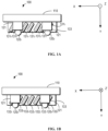
- FIG. 1A and 1B show a side view of a conveyor according to embodiments of the present disclosure.
- FIG. 1A may show the conveyor 100 from left side, i.e. in a direction Z while FIG. 1B show the conveyor 100 from the right side, i.e. in a direction Z' opposite to the direction Z.
- the direction Z and Z' are arranged to be normal to the direction X.
- the conveyor 100 may comprise a carrying member 110.
- An object to be conveyed may be carried by the carrying member 110 and transferred to a target destination.
- a plurality of rollers can be arranged under the carrying member 110.
- rollers 120 two pairs of rollers 120 1 , 120 2 and 120 3 and 120 4 , hereafter may be referred to rollers 120 collectively, can be mounted under the carrying member 110.
- the plurality of rollers 120 may be guided to be moved on the specific rails (not shown) along the driving direction X.
- a first magnetic engaging portion 130 may be arranged to extend from a lower surface of the carrying member 110 to a position near to the guide rails (not shown), on which the conveyor 100 can be guided to move, in a second direction Y.
- the first magnetic engaging portion 130 may comprises a first set of magnetic racks 131 0 -131 6 (as shown in FIG. 1A and hereafter may be also referred to as a first set of magnetic racks 131 collectively) and a second set of magnetic racks 132 0 -132 6 (as shown in FIG. 1B and hereafter may be also referred to as a second set of magnetic racks 132 collectively.)
- the second set of magnetic racks 132 may be arranged opposite to the first set of magnetic racks 131.
- first set of magnetic racks 131 0 -131 6 and the second set of magnetic racks 132 0 -132 6 may be covered by other elements, for example, a supporting element and therefore cannot be seen in the direction Z and Z'.
- the illustration of the magnetic racks as shown in FIGs. 1A and 1B is only for the sake of explanation.
- the first magnetic engaging portion 130 may comprise a pair of first supporting members 133, which may be arranged under the carrying member 110 and configured to support the first set of magnetic racks 131 and the second set of magnetic racks 132 respectively.
- the conveyor 100 may further comprises a pair of second supporting members 121 fixed on the lower surface of the carrying member 110.
- the plurality of rollers 120 may be mounted on the respective second supporting members 121.
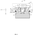
- FIG. 2 shows a front view of a conveying system 200 having a conveyor 100 according to embodiments of the present disclosure.
- the magnetic engagement arrangement according to the present disclosure may be further described in detail.
- a plurality of rollers 120 of the conveyor 100 can be guided to move along guide rails 220 in a driving direction X, for example, to transfer electronic components to be mounted in the clean room to the target destination.
- the first magnetic engaging portion 130 can extend from a lower surface of the carrying member 110 to a position near to the guide rails 220 in a direction Y, which may be normal to the driving direction X.
- the first magnetic engaging portion 130 may interact with a second magnetic engaging portion 210, to generate a driving force in the driving direction X, so that the conveyor 100 may be driven by the driving force.
- the first magnetic engaging portion 130 of the conveyor 100 may be disposed closer to the second magnetic engagement portion 210 and therefore may interact better with the second magnetic engagement portion 210 when a magnetic field is generated at the second magnetic engagement portion 210.
- a sufficient driving force can be generated to improve the carrying capacity of the conveyor 100.
- the first magnetic engaging portion of the first aspect makes it easier to separate the first magnetic engaging portion from the the second magnetic engagement portion at a tangible direction of the the second magnetic engagement portion. Without step change of magnetic force during separating, the lifting up motion can be smoother.
- the second set of magnetic racks 132 may be arranged opposite to the first set of magnetic racks 131 at a predetermined distance d from the first set of magnetic racks 131 such that the second magnetic engaging portion 210 is located between the first set of magnetic racks 131 and the second set of magnetic racks 132.
- a plurality of magnetic racks 131 and 132 can be arranged around the second magnetic engaging portion 210, which may protrude from the guide rails 220 such that the magnetic engagement between the first magnetic engaging portion 130 and the second magnetic engaging portion 210 becomes more strengthen. Therefore, the driving capacity of the magnetic conveyor 100, especially the speed and load capacity of the conveyor 100 can be significantly increased with the embraced magnetic field engagement around the second magnetic engaging portion 210.
- the first magnetic engaging portion 130 may further comprise a connecting element 134 fixed on the lower surface of the carrying member 110 and a pair of first supporting members 133 connected to the connecting element 134, by which the first set of magnetic racks 131 and the second set of magnetic racks 132 may be supported respectively.
- connection element By using the connecting element and the pair of first supporting members, a simple and stable connection of plurality of sets of magnetic racks to the carrying member may be achieved, which is an indispensable intermediate structure for implementing the magnetic rack arrangement of the present disclosure.
- a pair of second supporting members 121 may be fixed on the lower surface of the carrying member 110 and the plurality of rollers 120 may be mounted on the respective second supporting members 121.
- a height H2 from a lower end of the connecting element to a bottom of the magnetic engagement portion is greater than a height H1 of the second magnetic engagement portion.
- the conveyor 100 may further comprise a pair of third supporting members 122 fixed on the respective second supporting members 121 and limiting member 123 mounted in the respective third supporting members 122 and adapted to limit the movement of the conveyor on the guide rails 220.
- the limiting member 123 may be formed as a roller.
- the limiting member 123 may also be formed as a limiting block. In this way, the conveyor can be maintained on the guide rails to ensure a stable conveying process.
- the first set of magnetic racks 131 0 -131 6 and the second set of magnetic racks 132 0 -132 6 may be arranged to be inclined in opposite directions with respect to the second direction Y on the respective first supporting members 133.
- each of the first set of magnetic racks 131 0 -131 6 may be inclined to form a predetermined angle with the respective ones of the second set of magnetic racks 132 0 -132 6 .
- FIG. 3B shows the angle ⁇ formed between the magnetic rack 131 0 and the magnetic rack 132 0 when assuming that the magnetic rack 131 0 and the magnetic rack 132 0 are placed in a same plane.
- the predetermined angle ⁇ may corresponds to half of an inclination angle of a magnetic pole generated by the second magnetic engagement portion 210 with respect to the direction Y.
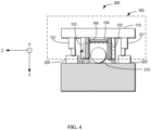
- FIG. 4 shows a front view of a conveying system 200 having a further conveyor 100 according to embodiments of the present disclosure.
- the most components and structures shown in FIG. 4 are same or similar with the conveyor shown in FIG. 2 , which may not be repetitively explained here.
- the conveyor 100 shown in FIG. 4 may further comprise a third magnetic engaging portion 140 arranged on the connecting element 134.
- the third magnetic engaging portion 140 may also be interact with the second magnetic engaging portion210 on the guide rails 220, which may further increase the driving capacity of the magnetic conveyor.
- FIG. 5A and 5B show a side view of a conveying system having the conveyor according to further embodiments of the present disclosure.
- FIG. 5A may show the conveying system 200 from left side (in a direction Z) while FIG. 5B show the conveying system 200 from the right side (in a direction Z').
- a conveying system will be explained as below.
- the conveying system 200 comprises a conveyor 100 which has been described above.
- the conveying system 200 may further comprise guide rails 220, which can guide the plurality of rollers 120 of the conveyor 100, to move the conveyor 100 in the driving direction X.
- the conveying system 200 may also comprise a driving shaft 230.
- the conveyor 100 may be arranged between the guide rails 220.
- the driving shaft 230 may be driven to rotate in a rotating direction R. It should be understood that only a schematic rotating direction R is shown in FIGs. 5A and 5B , which can be set to be clockwise or counterclockwise depending on the application.
- the conveying system 200 may also comprise a second magnetic engaging portion 210 comprising a plurality of magnetic gear arranged on the driving shaft 230.
- the plurality of magnetic gear may be configured to rotate with the rotation of the driving shaft 230, to generate a magnetic field.
- the conveying system 200 may also comprise a motor M, which may be configured to apply the power to the driving shaft 230, to drive the driving shaft to be rotated.
- a motor M which may be configured to apply the power to the driving shaft 230, to drive the driving shaft to be rotated.
- FIG. 6 shows a flowchart illustrating a manufacturing method of a conveyor according to embodiments of the present disclosure.
- the method 600 may be implemented for manufacturing the conveyor 100 described with reference to FIG. 1A to FIG. 4 .
- a carrying member is provided to carry an object to be conveyed.
- a plurality of rollers is arranged under the carrying member. The plurality of rollers is adapted to be guided to move along guide rails in a first direction.
- a first magnetic engaging portion is arranged to extend from a lower surface of the carrying member to a position near to the guide rails in a second direction normal to the first direction.
- the first magnetic engaging portion can interact with a second magnetic engaging portion on the guide rails, to generate a driving force for driving the conveyor in the first direction.
- the conveyor of the first aspect of can be manufactured with a simple structure and low cost.
- the conventional magnetic conveyor can be replaced by the conveyor according to the first aspect, without having to replace other components, such as guide rail, in the conveying system.
Landscapes
- Non-Mechanical Conveyors (AREA)
Claims (9)
- Förderer (100), umfassend:ein Tragelement (110), das dazu ausgelegt ist, einen zu befördernden Gegenstand zu tragen;eine Vielzahl von Rollen (120), die unter dem Tragelement (110) angeordnet sind und dazu ausgelegt sind, geführt zu werden, um sich entlang von Führungsschienen (220) in einer ersten Richtung (X) zu bewegen; undeinen ersten magnetischen Eingriffsabschnitt (130), der so angeordnet ist, dass er sich von einer unteren Fläche des Tragelements (110) zu einer Position in der Nähe der Führungsschienen (220) in einer zweiten Richtung (Y) senkrecht zur ersten Richtung (X) erstreckt, und der so ausgelegt ist, dass er mit einem zweiten magnetischen Eingriffsabschnitt (210) an den Führungsschienen (220) zusammenwirkt, um eine Antriebskraft zum Antreiben des Förderers (100) in der ersten Richtung (X) zu erzeugen;wobei der erste magnetische Eingriffsabschnitt (130) umfasst:einen ersten Satz magnetischer Zahnstangen (131); wobei der Förderer dadurch gekennzeichnet ist, dass der erste magnetische Eingriffsabschnitt (130) ferner umfassteinen zweiten Satz magnetischer Zahnstangen (132), die dem ersten Satz magnetischer Zahnstangen (131) gegenüberliegend in einem vorbestimmten Abstand (d) von dem ersten Satz magnetischer Zahnstangen (131) angeordnet sind, so dass der zweite magnetische Eingriffsabschnitt (210) zwischen dem ersten Satz magnetischer Zahnstangen (131) und dem zweiten Satz magnetischer Zahnstangen (132) anordbar ist;wobei der erste magnetische Eingriffsabschnitt (130) ferner umfasst:ein Verbindungselement (134), das an der unteren Fläche des Tragelements (110) befestigt ist; undein Paar erster Stützelemente (133), die mit dem Verbindungselement (134) verbunden sind und dazu ausgelegt sind, den ersten Satz magnetischer Zahnstangen (131) bzw. den zweiten Satz magnetischer Zahnstangen (132) zu stützen.
- Förderer (100) nach Anspruch 1, wobei der erste Satz magnetischer Zahnstangen (131) und der zweite Satz magnetischer Zahnstangen (132) so angeordnet sind, dass sie in entgegengesetzten Richtungen in Bezug auf die zweite Richtung (Y) auf den jeweiligen ersten Stützelementen (133) geneigt sind.
- Förderer (100) nach Anspruch 2, wobei der erste Satz von magnetischen Zahnstangen (131) geneigt ist, um einen vorbestimmten Winkel θ mit dem zweiten Satz von magnetischer Zahnstangen (132) zu bilden, und wobei der vorbestimmte Winkel θ mit der Hälfte eines Neigungswinkels eines Magnetpols korrespondiert, der durch den zweiten magnetischen Eingriffsabschnitt (210) in Bezug auf die zweite Richtung (Y) erzeugt wird.
- Förderer (100) nach Anspruch 1, wobei der Förderer (100) ferner einen dritten magnetischen Eingriffsabschnitt (140) umfasst, der an dem Verbindungselement (134) angeordnet ist und mit dem zweiten magnetischen Eingriffsabschnitt (210) an den Führungsschienen (220) zusammenwirken kann.
- Förderer (100) nach Anspruch 1, wobei der Förderer (100) ferner ein Paar zweiter Stützelemente (121) umfasst, die an der unteren Fläche des Tragelements (110) befestigt sind, und
wobei die Vielzahl von Rollen (120) an den jeweiligen zweiten Stützelementen (121) so angebracht sind, dass eine zweite Höhe (H2) von einem unteren Ende des Verbindungselements (134) zu einem Boden des magnetischen Eingriffsabschnitts (210) größer ist als eine erste Höhe (H1) des zweiten magnetischen Eingriffsabschnitts (210). - Förderer (100) nach Anspruch 1, wobei der Förderer (100) ferner umfasst:ein Paar dritter Stützelemente (122), die an den jeweiligen zweiten Stützelementen (121) befestigt sind; undein Begrenzungselement (123), das in den jeweiligen dritten Stützelementen (122) angebracht ist und dazu ausgelegt ist, die Bewegung des Förderers (100) auf den Führungsschienen (220) zu begrenzen.
- Fördersystem (200), umfassend:einen Förderer (100) gemäß einem der Ansprüche 1 bis 6; undFührungsschienen (210), die dazu ausgelegt sind, die Vielzahl von Rollen (120) zu führen, um den Förderer (100) in die erste Richtung (X) zu bewegen;eine Antriebswelle (230), die zwischen den Führungsschienen (210) angeordnet ist und angetrieben werden kann, um sich in einer dritten Richtung (R) zu drehen; undeinen zweiten magnetischen Eingriffsabschnitt (210), der eine Vielzahl von Magnetzahnrädern umfasst, die auf der Antriebswelle (230) angeordnet sind und sich mit der Drehung der Antriebswelle (230) drehen können, um ein Magnetfeld zu erzeugen.
- Fördersystem (200) nach Anspruch 7, das ferner einen Motor (M) umfasst, der zum Antrieb der Antriebswelle (230) ausgelegt ist.
- Herstellungsverfahren eines Förderers (100), umfassend:Bereitstellen eines Tragelements (110), das zum Tragen eines zu befördernden Objekts angepasst ist;Anordnen einer Vielzahl von Rollen (120) unter dem Tragelement (110), wobei die Vielzahl von Rollen (120) angepasst ist, um entlang von Führungsschienen (220) in einer ersten Richtung (X) geführt zu werden; undAnordnen eines ersten magnetischen Eingriffsabschnitts (130), der sich von einer unteren Fläche des Tragelements (110) zu einer Position in der Nähe der Führungsschienen (220) in einer zweiten Richtung (Y) senkrecht zur ersten Richtung (X) erstreckt und der so angepasst ist, dass er mit einem zweiten magnetischen Eingriffsabschnitt (210) an den Führungsschienen (220) zusammenwirkt, um eine Antriebskraft zum Antreiben des Förderers (100) in der ersten Richtung (X) zu erzeugen;wobei der erste magnetische Eingriffsabschnitt (130) umfasst:einen ersten Satz magnetischer Zahnstangen (131); wobei das Verfahren dadurch gekennzeichnet ist, dass der erste magnetische Eingriffsabschnitt ferner umfassteinen zweiten Satz magnetischer Zahnstangen (132), die dem ersten Satz magnetischer Zahnstangen (131) gegenüberliegend in einem vorbestimmten Abstand (d) von dem ersten Satz magnetischer Zahnstangen (131) angeordnet sind, so dass der zweite magnetische Eingriffsabschnitt (210) zwischen dem ersten Satz magnetischer Zahnstangen (131) und dem zweiten Satz magnetischer Zahnstangen (132) anordbar ist;wobei der erste magnetische Eingriffsabschnitt (130) ferner umfasst:ein Verbindungselement (134), das an der unteren Fläche des Tragelements (110) befestigt ist; undein Paar erster Stützelemente (133), die mit dem Verbindungselement (134) verbunden sind und so angepasst sind, dass sie den ersten Satz magnetischer Zahnstangen (131) bzw. den zweiten Satz magnetischer Zahnstangen (132) stützen.
Applications Claiming Priority (1)
| Application Number | Priority Date | Filing Date | Title |
|---|---|---|---|
| PCT/CN2019/120267 WO2021097806A1 (en) | 2019-11-22 | 2019-11-22 | Conveyor, conveying system and manufacturing method of conveyor |
Publications (3)
| Publication Number | Publication Date |
|---|---|
| EP4061752A1 EP4061752A1 (de) | 2022-09-28 |
| EP4061752A4 EP4061752A4 (de) | 2023-08-23 |
| EP4061752B1 true EP4061752B1 (de) | 2025-03-12 |
Family
ID=75980077
Family Applications (1)
| Application Number | Title | Priority Date | Filing Date |
|---|---|---|---|
| EP19953703.6A Active EP4061752B1 (de) | 2019-11-22 | 2019-11-22 | Förderer, fördersystem und verfahren zur herstellung eines förderers |
Country Status (4)
| Country | Link |
|---|---|
| US (1) | US11780688B2 (de) |
| EP (1) | EP4061752B1 (de) |
| CN (1) | CN114616198A (de) |
| WO (1) | WO2021097806A1 (de) |
Families Citing this family (2)
| Publication number | Priority date | Publication date | Assignee | Title |
|---|---|---|---|---|
| EP4299492B1 (de) * | 2022-07-01 | 2026-03-18 | Schneider Electric Industries SAS | Transportsystem |
| DE102024121798A1 (de) * | 2024-07-31 | 2026-02-05 | maG Holding GmbH | Fördertechnikmodul mit einem Antrieb für entlang des Fördertechnikmoduls verfahrbare Schlitten |
Family Cites Families (16)
| Publication number | Priority date | Publication date | Assignee | Title |
|---|---|---|---|---|
| US3049441A (en) * | 1959-10-09 | 1962-08-14 | United States Steel Corp | Method of and apparatus for preventing edge build-up of coating material on dip-coated strip |
| JPH10287233A (ja) * | 1997-04-15 | 1998-10-27 | Mitsubishi Heavy Ind Ltd | 搬送台車装置 |
| JP2000191140A (ja) * | 1998-12-26 | 2000-07-11 | Minebea Co Ltd | リニアモ―タを用いた搬送システム |
| KR100699271B1 (ko) | 2005-11-22 | 2007-03-28 | 삼성전자주식회사 | 이송장치 |
| DE102010027925A1 (de) * | 2010-04-19 | 2011-10-20 | Robert Bosch Gmbh | Transportvorrichtung mit gelenkigem Förderelement |
| US9123507B2 (en) * | 2012-03-20 | 2015-09-01 | Mapper Lithography Ip B.V. | Arrangement and method for transporting radicals |
| DE102014214107A1 (de) | 2013-08-26 | 2015-02-26 | Robert Bosch Gmbh | Transportvorrichtung |
| DE102013216958A1 (de) * | 2013-08-26 | 2015-02-26 | Robert Bosch Gmbh | Transfervorrichtung |
| JP6313642B2 (ja) * | 2014-04-18 | 2018-04-18 | キヤノン株式会社 | リニアモータ制御装置及びリニアモータ制御システム |
| DE102014117150A1 (de) * | 2014-11-24 | 2016-05-25 | Beckhoff Automation Gmbh | XY-Tisch für ein lineares Transportsystem |
| EP3034414B1 (de) * | 2014-12-19 | 2017-02-22 | UHLMANN PAC-SYSTEME GmbH & Co. KG | Verfahren zum Übertragen von Packgut in Behältnisse und zum Weitertransport der befüllten Behältnisse |
| CN105151803B (zh) | 2015-09-24 | 2018-03-27 | Abb瑞士股份有限公司 | 输送装置及其传输系统 |
| HUE069604T2 (hu) * | 2016-12-27 | 2025-03-28 | Abb Schweiz Ag | Szállítórendszer |
| WO2018145214A1 (en) * | 2017-02-13 | 2018-08-16 | Ats Automation Tooling Systems Inc. | Linear motor conveyor system and moving elements therefor providing a reduced tooling pitch |
| JP6724239B2 (ja) * | 2017-02-24 | 2020-07-15 | アーベーベー・シュバイツ・アーゲー | 補助搬送機及び対応する搬送システム |
| EP3597471A1 (de) * | 2018-07-18 | 2020-01-22 | B&R Industrial Automation GmbH | Langstatorlinearmotor |
-
2019
- 2019-11-22 EP EP19953703.6A patent/EP4061752B1/de active Active
- 2019-11-22 WO PCT/CN2019/120267 patent/WO2021097806A1/en not_active Ceased
- 2019-11-22 US US17/755,270 patent/US11780688B2/en active Active
- 2019-11-22 CN CN201980101532.5A patent/CN114616198A/zh active Pending
Also Published As
| Publication number | Publication date |
|---|---|
| CN114616198A (zh) | 2022-06-10 |
| EP4061752A1 (de) | 2022-09-28 |
| EP4061752A4 (de) | 2023-08-23 |
| WO2021097806A1 (en) | 2021-05-27 |
| US20220388789A1 (en) | 2022-12-08 |
| US11780688B2 (en) | 2023-10-10 |
Similar Documents
| Publication | Publication Date | Title |
|---|---|---|
| CN104175316B (zh) | 机械手臂 | |
| US20150225216A1 (en) | Stacker crane | |
| EP4061752B1 (de) | Förderer, fördersystem und verfahren zur herstellung eines förderers | |
| KR102636126B1 (ko) | 물품 반송차 | |
| KR101960679B1 (ko) | 가이드휠을 장착한 롤러 유닛 및 이를 이용한 팰릿 이송 시스템 | |
| US11904461B2 (en) | Payload transportation device | |
| KR101997053B1 (ko) | 리니어 모터를 이용하여 충돌방지 및 연속주행 기능을 갖는 팰릿 이송 제어시스템 및 그 제어방법 | |
| CN111099251A (zh) | 一种输送系统 | |
| KR102813787B1 (ko) | 컨베이어 장치용 디버터 | |
| CN102101572A (zh) | 多辊输送机 | |
| US20230101404A1 (en) | Payload lifting device | |
| KR101448474B1 (ko) | 이송 경로 전환 장치 | |
| CN111792261A (zh) | 一种道岔式立体库 | |
| CN109533085B (zh) | 一种重载agv | |
| KR102736428B1 (ko) | 반전 이송 시스템 | |
| WO2020119388A1 (zh) | 自动导引车辆的无弹性悬架结构 | |
| CN110481687A (zh) | 一种轮球式平衡车 | |
| WO2024001951A1 (zh) | 搬运机器人的提升装置及搬运机器人 | |
| KR101993823B1 (ko) | 리니어모터의 방열구조를 갖는 팰릿 이송 제어시스템 | |
| KR101207897B1 (ko) | 멀티 게이트 컨베이어 | |
| KR101157196B1 (ko) | 이송장치 | |
| CN221234601U (zh) | 动态误差补偿结构、输送线以及输送装置 | |
| KR101308988B1 (ko) | 반송 로봇 | |
| WO2025086305A1 (en) | Lifting apparatus and lifting system | |
| CN217024290U (zh) | 一种货件稳定转向装置及运输系统 |
Legal Events
| Date | Code | Title | Description |
|---|---|---|---|
| STAA | Information on the status of an ep patent application or granted ep patent |
Free format text: STATUS: THE INTERNATIONAL PUBLICATION HAS BEEN MADE |
|
| PUAI | Public reference made under article 153(3) epc to a published international application that has entered the european phase |
Free format text: ORIGINAL CODE: 0009012 |
|
| STAA | Information on the status of an ep patent application or granted ep patent |
Free format text: STATUS: REQUEST FOR EXAMINATION WAS MADE |
|
| 17P | Request for examination filed |
Effective date: 20220411 |
|
| AK | Designated contracting states |
Kind code of ref document: A1 Designated state(s): AL AT BE BG CH CY CZ DE DK EE ES FI FR GB GR HR HU IE IS IT LI LT LU LV MC MK MT NL NO PL PT RO RS SE SI SK SM TR |
|
| DAV | Request for validation of the european patent (deleted) | ||
| DAX | Request for extension of the european patent (deleted) | ||
| A4 | Supplementary search report drawn up and despatched |
Effective date: 20230720 |
|
| RIC1 | Information provided on ipc code assigned before grant |
Ipc: B65G 54/02 20060101AFI20230714BHEP |
|
| GRAP | Despatch of communication of intention to grant a patent |
Free format text: ORIGINAL CODE: EPIDOSNIGR1 |
|
| STAA | Information on the status of an ep patent application or granted ep patent |
Free format text: STATUS: GRANT OF PATENT IS INTENDED |
|
| INTG | Intention to grant announced |
Effective date: 20241217 |
|
| GRAS | Grant fee paid |
Free format text: ORIGINAL CODE: EPIDOSNIGR3 |
|
| GRAA | (expected) grant |
Free format text: ORIGINAL CODE: 0009210 |
|
| STAA | Information on the status of an ep patent application or granted ep patent |
Free format text: STATUS: THE PATENT HAS BEEN GRANTED |
|
| AK | Designated contracting states |
Kind code of ref document: B1 Designated state(s): AL AT BE BG CH CY CZ DE DK EE ES FI FR GB GR HR HU IE IS IT LI LT LU LV MC MK MT NL NO PL PT RO RS SE SI SK SM TR |
|
| REG | Reference to a national code |
Ref country code: GB Ref legal event code: FG4D |
|
| REG | Reference to a national code |
Ref country code: CH Ref legal event code: EP |
|
| REG | Reference to a national code |
Ref country code: DE Ref legal event code: R096 Ref document number: 602019067361 Country of ref document: DE |
|
| REG | Reference to a national code |
Ref country code: IE Ref legal event code: FG4D |
|
| PG25 | Lapsed in a contracting state [announced via postgrant information from national office to epo] |
Ref country code: RS Free format text: LAPSE BECAUSE OF FAILURE TO SUBMIT A TRANSLATION OF THE DESCRIPTION OR TO PAY THE FEE WITHIN THE PRESCRIBED TIME-LIMIT Effective date: 20250612 |
|
| PG25 | Lapsed in a contracting state [announced via postgrant information from national office to epo] |
Ref country code: FI Free format text: LAPSE BECAUSE OF FAILURE TO SUBMIT A TRANSLATION OF THE DESCRIPTION OR TO PAY THE FEE WITHIN THE PRESCRIBED TIME-LIMIT Effective date: 20250312 |
|
| PG25 | Lapsed in a contracting state [announced via postgrant information from national office to epo] |
Ref country code: ES Free format text: LAPSE BECAUSE OF FAILURE TO SUBMIT A TRANSLATION OF THE DESCRIPTION OR TO PAY THE FEE WITHIN THE PRESCRIBED TIME-LIMIT Effective date: 20250312 |
|
| REG | Reference to a national code |
Ref country code: LT Ref legal event code: MG9D |
|
| PG25 | Lapsed in a contracting state [announced via postgrant information from national office to epo] |
Ref country code: NO Free format text: LAPSE BECAUSE OF FAILURE TO SUBMIT A TRANSLATION OF THE DESCRIPTION OR TO PAY THE FEE WITHIN THE PRESCRIBED TIME-LIMIT Effective date: 20250612 |
|
| PG25 | Lapsed in a contracting state [announced via postgrant information from national office to epo] |
Ref country code: HR Free format text: LAPSE BECAUSE OF FAILURE TO SUBMIT A TRANSLATION OF THE DESCRIPTION OR TO PAY THE FEE WITHIN THE PRESCRIBED TIME-LIMIT Effective date: 20250312 |
|
| REG | Reference to a national code |
Ref country code: NL Ref legal event code: MP Effective date: 20250312 |
|
| PG25 | Lapsed in a contracting state [announced via postgrant information from national office to epo] |
Ref country code: LV Free format text: LAPSE BECAUSE OF FAILURE TO SUBMIT A TRANSLATION OF THE DESCRIPTION OR TO PAY THE FEE WITHIN THE PRESCRIBED TIME-LIMIT Effective date: 20250312 |
|
| PG25 | Lapsed in a contracting state [announced via postgrant information from national office to epo] |
Ref country code: BG Free format text: LAPSE BECAUSE OF FAILURE TO SUBMIT A TRANSLATION OF THE DESCRIPTION OR TO PAY THE FEE WITHIN THE PRESCRIBED TIME-LIMIT Effective date: 20250312 Ref country code: GR Free format text: LAPSE BECAUSE OF FAILURE TO SUBMIT A TRANSLATION OF THE DESCRIPTION OR TO PAY THE FEE WITHIN THE PRESCRIBED TIME-LIMIT Effective date: 20250613 |
|
| REG | Reference to a national code |
Ref country code: AT Ref legal event code: MK05 Ref document number: 1774887 Country of ref document: AT Kind code of ref document: T Effective date: 20250312 |
|
| PG25 | Lapsed in a contracting state [announced via postgrant information from national office to epo] |
Ref country code: NL Free format text: LAPSE BECAUSE OF FAILURE TO SUBMIT A TRANSLATION OF THE DESCRIPTION OR TO PAY THE FEE WITHIN THE PRESCRIBED TIME-LIMIT Effective date: 20250312 |
|
| PG25 | Lapsed in a contracting state [announced via postgrant information from national office to epo] |
Ref country code: SE Free format text: LAPSE BECAUSE OF FAILURE TO SUBMIT A TRANSLATION OF THE DESCRIPTION OR TO PAY THE FEE WITHIN THE PRESCRIBED TIME-LIMIT Effective date: 20250312 |
|
| PG25 | Lapsed in a contracting state [announced via postgrant information from national office to epo] |
Ref country code: SM Free format text: LAPSE BECAUSE OF FAILURE TO SUBMIT A TRANSLATION OF THE DESCRIPTION OR TO PAY THE FEE WITHIN THE PRESCRIBED TIME-LIMIT Effective date: 20250312 |
|
| PG25 | Lapsed in a contracting state [announced via postgrant information from national office to epo] |
Ref country code: PT Free format text: LAPSE BECAUSE OF FAILURE TO SUBMIT A TRANSLATION OF THE DESCRIPTION OR TO PAY THE FEE WITHIN THE PRESCRIBED TIME-LIMIT Effective date: 20250714 |
|
| PG25 | Lapsed in a contracting state [announced via postgrant information from national office to epo] |
Ref country code: PL Free format text: LAPSE BECAUSE OF FAILURE TO SUBMIT A TRANSLATION OF THE DESCRIPTION OR TO PAY THE FEE WITHIN THE PRESCRIBED TIME-LIMIT Effective date: 20250312 Ref country code: IT Free format text: LAPSE BECAUSE OF FAILURE TO SUBMIT A TRANSLATION OF THE DESCRIPTION OR TO PAY THE FEE WITHIN THE PRESCRIBED TIME-LIMIT Effective date: 20250312 |
|
| PG25 | Lapsed in a contracting state [announced via postgrant information from national office to epo] |
Ref country code: AT Free format text: LAPSE BECAUSE OF FAILURE TO SUBMIT A TRANSLATION OF THE DESCRIPTION OR TO PAY THE FEE WITHIN THE PRESCRIBED TIME-LIMIT Effective date: 20250312 |
|
| PG25 | Lapsed in a contracting state [announced via postgrant information from national office to epo] |
Ref country code: CZ Free format text: LAPSE BECAUSE OF FAILURE TO SUBMIT A TRANSLATION OF THE DESCRIPTION OR TO PAY THE FEE WITHIN THE PRESCRIBED TIME-LIMIT Effective date: 20250312 Ref country code: EE Free format text: LAPSE BECAUSE OF FAILURE TO SUBMIT A TRANSLATION OF THE DESCRIPTION OR TO PAY THE FEE WITHIN THE PRESCRIBED TIME-LIMIT Effective date: 20250312 |
|
| PG25 | Lapsed in a contracting state [announced via postgrant information from national office to epo] |
Ref country code: RO Free format text: LAPSE BECAUSE OF FAILURE TO SUBMIT A TRANSLATION OF THE DESCRIPTION OR TO PAY THE FEE WITHIN THE PRESCRIBED TIME-LIMIT Effective date: 20250312 |
|
| PG25 | Lapsed in a contracting state [announced via postgrant information from national office to epo] |
Ref country code: SK Free format text: LAPSE BECAUSE OF FAILURE TO SUBMIT A TRANSLATION OF THE DESCRIPTION OR TO PAY THE FEE WITHIN THE PRESCRIBED TIME-LIMIT Effective date: 20250312 |
|
| PG25 | Lapsed in a contracting state [announced via postgrant information from national office to epo] |
Ref country code: IS Free format text: LAPSE BECAUSE OF FAILURE TO SUBMIT A TRANSLATION OF THE DESCRIPTION OR TO PAY THE FEE WITHIN THE PRESCRIBED TIME-LIMIT Effective date: 20250712 |
|
| REG | Reference to a national code |
Ref country code: DE Ref legal event code: R097 Ref document number: 602019067361 Country of ref document: DE |
|
| PGFP | Annual fee paid to national office [announced via postgrant information from national office to epo] |
Ref country code: DE Payment date: 20251119 Year of fee payment: 7 |
|
| PG25 | Lapsed in a contracting state [announced via postgrant information from national office to epo] |
Ref country code: DK Free format text: LAPSE BECAUSE OF FAILURE TO SUBMIT A TRANSLATION OF THE DESCRIPTION OR TO PAY THE FEE WITHIN THE PRESCRIBED TIME-LIMIT Effective date: 20250312 |
|
| PLBE | No opposition filed within time limit |
Free format text: ORIGINAL CODE: 0009261 |
|
| STAA | Information on the status of an ep patent application or granted ep patent |
Free format text: STATUS: NO OPPOSITION FILED WITHIN TIME LIMIT |
|
| REG | Reference to a national code |
Ref country code: CH Ref legal event code: L10 Free format text: ST27 STATUS EVENT CODE: U-0-0-L10-L00 (AS PROVIDED BY THE NATIONAL OFFICE) Effective date: 20260121 |
|
| 26N | No opposition filed |
Effective date: 20251215 |