EP4062085B1 - Getriebeanordnung für einen antriebsstrang eines kraftfahrzeuges - Google Patents
Getriebeanordnung für einen antriebsstrang eines kraftfahrzeuges Download PDFInfo
- Publication number
- EP4062085B1 EP4062085B1 EP19808786.8A EP19808786A EP4062085B1 EP 4062085 B1 EP4062085 B1 EP 4062085B1 EP 19808786 A EP19808786 A EP 19808786A EP 4062085 B1 EP4062085 B1 EP 4062085B1
- Authority
- EP
- European Patent Office
- Prior art keywords
- transmission
- mounting surface
- control device
- guiding member
- outwardly extending
- Prior art date
- Legal status (The legal status is an assumption and is not a legal conclusion. Google has not performed a legal analysis and makes no representation as to the accuracy of the status listed.)
- Active
Links
Images


Classifications
-
- F—MECHANICAL ENGINEERING; LIGHTING; HEATING; WEAPONS; BLASTING
- F16—ENGINEERING ELEMENTS AND UNITS; GENERAL MEASURES FOR PRODUCING AND MAINTAINING EFFECTIVE FUNCTIONING OF MACHINES OR INSTALLATIONS; THERMAL INSULATION IN GENERAL
- F16H—GEARING
- F16H57/00—General details of gearing
- F16H57/02—Gearboxes; Mounting gearing therein
-
- F—MECHANICAL ENGINEERING; LIGHTING; HEATING; WEAPONS; BLASTING
- F16—ENGINEERING ELEMENTS AND UNITS; GENERAL MEASURES FOR PRODUCING AND MAINTAINING EFFECTIVE FUNCTIONING OF MACHINES OR INSTALLATIONS; THERMAL INSULATION IN GENERAL
- F16H—GEARING
- F16H61/00—Control functions within control units of change-speed- or reversing-gearings for conveying rotary motion ; Control of exclusively fluid gearing, friction gearing, gearings with endless flexible members or other particular types of gearing
- F16H61/0003—Arrangement or mounting of elements of the control apparatus, e.g. valve assemblies or snapfittings of valves; Arrangements of the control unit on or in the transmission gearbox
-
- B—PERFORMING OPERATIONS; TRANSPORTING
- B60—VEHICLES IN GENERAL
- B60K—ARRANGEMENT OR MOUNTING OF PROPULSION UNITS OR OF TRANSMISSIONS IN VEHICLES; ARRANGEMENT OR MOUNTING OF PLURAL DIVERSE PRIME-MOVERS IN VEHICLES; AUXILIARY DRIVES FOR VEHICLES; INSTRUMENTATION OR DASHBOARDS FOR VEHICLES; ARRANGEMENTS IN CONNECTION WITH COOLING, AIR INTAKE, GAS EXHAUST OR FUEL SUPPLY OF PROPULSION UNITS IN VEHICLES
- B60K1/00—Arrangement or mounting of electrical propulsion units
- B60K1/02—Arrangement or mounting of electrical propulsion units comprising more than one electric motor
-
- B—PERFORMING OPERATIONS; TRANSPORTING
- B60—VEHICLES IN GENERAL
- B60K—ARRANGEMENT OR MOUNTING OF PROPULSION UNITS OR OF TRANSMISSIONS IN VEHICLES; ARRANGEMENT OR MOUNTING OF PLURAL DIVERSE PRIME-MOVERS IN VEHICLES; AUXILIARY DRIVES FOR VEHICLES; INSTRUMENTATION OR DASHBOARDS FOR VEHICLES; ARRANGEMENTS IN CONNECTION WITH COOLING, AIR INTAKE, GAS EXHAUST OR FUEL SUPPLY OF PROPULSION UNITS IN VEHICLES
- B60K23/00—Arrangement or mounting of control devices for vehicle transmissions, or parts thereof, not otherwise provided for
-
- F—MECHANICAL ENGINEERING; LIGHTING; HEATING; WEAPONS; BLASTING
- F16—ENGINEERING ELEMENTS AND UNITS; GENERAL MEASURES FOR PRODUCING AND MAINTAINING EFFECTIVE FUNCTIONING OF MACHINES OR INSTALLATIONS; THERMAL INSULATION IN GENERAL
- F16H—GEARING
- F16H61/00—Control functions within control units of change-speed- or reversing-gearings for conveying rotary motion ; Control of exclusively fluid gearing, friction gearing, gearings with endless flexible members or other particular types of gearing
- F16H61/0003—Arrangement or mounting of elements of the control apparatus, e.g. valve assemblies or snapfittings of valves; Arrangements of the control unit on or in the transmission gearbox
- F16H61/0006—Electronic control units for transmission control, e.g. connectors, casings or circuit boards
-
- F—MECHANICAL ENGINEERING; LIGHTING; HEATING; WEAPONS; BLASTING
- F16—ENGINEERING ELEMENTS AND UNITS; GENERAL MEASURES FOR PRODUCING AND MAINTAINING EFFECTIVE FUNCTIONING OF MACHINES OR INSTALLATIONS; THERMAL INSULATION IN GENERAL
- F16H—GEARING
- F16H57/00—General details of gearing
- F16H2057/0056—Mounting parts arranged in special position or by special sequence, e.g. for keeping particular parts in his position during assembly
-
- F—MECHANICAL ENGINEERING; LIGHTING; HEATING; WEAPONS; BLASTING
- F16—ENGINEERING ELEMENTS AND UNITS; GENERAL MEASURES FOR PRODUCING AND MAINTAINING EFFECTIVE FUNCTIONING OF MACHINES OR INSTALLATIONS; THERMAL INSULATION IN GENERAL
- F16H—GEARING
- F16H57/00—General details of gearing
- F16H57/02—Gearboxes; Mounting gearing therein
- F16H2057/02026—Connection of auxiliaries with a gear case; Mounting of auxiliaries on the gearbox
-
- F—MECHANICAL ENGINEERING; LIGHTING; HEATING; WEAPONS; BLASTING
- F16—ENGINEERING ELEMENTS AND UNITS; GENERAL MEASURES FOR PRODUCING AND MAINTAINING EFFECTIVE FUNCTIONING OF MACHINES OR INSTALLATIONS; THERMAL INSULATION IN GENERAL
- F16H—GEARING
- F16H57/00—General details of gearing
- F16H57/02—Gearboxes; Mounting gearing therein
- F16H2057/02034—Gearboxes combined or connected with electric machines
-
- F—MECHANICAL ENGINEERING; LIGHTING; HEATING; WEAPONS; BLASTING
- F16—ENGINEERING ELEMENTS AND UNITS; GENERAL MEASURES FOR PRODUCING AND MAINTAINING EFFECTIVE FUNCTIONING OF MACHINES OR INSTALLATIONS; THERMAL INSULATION IN GENERAL
- F16H—GEARING
- F16H57/00—General details of gearing
- F16H57/02—Gearboxes; Mounting gearing therein
- F16H2057/02039—Gearboxes for particular applications
- F16H2057/02043—Gearboxes for particular applications for vehicle transmissions
-
- F—MECHANICAL ENGINEERING; LIGHTING; HEATING; WEAPONS; BLASTING
- F16—ENGINEERING ELEMENTS AND UNITS; GENERAL MEASURES FOR PRODUCING AND MAINTAINING EFFECTIVE FUNCTIONING OF MACHINES OR INSTALLATIONS; THERMAL INSULATION IN GENERAL
- F16H—GEARING
- F16H63/00—Control outputs from the control unit to change-speed- or reversing-gearings for conveying rotary motion or to other devices than the final output mechanism
- F16H63/02—Final output mechanisms therefor; Actuating means for the final output mechanisms
- F16H63/30—Constructional features of the final output mechanisms
- F16H2063/3076—Selector shaft assembly, e.g. supporting, assembly or manufacturing of selector or shift shafts; Special details thereof
-
- F—MECHANICAL ENGINEERING; LIGHTING; HEATING; WEAPONS; BLASTING
- F16—ENGINEERING ELEMENTS AND UNITS; GENERAL MEASURES FOR PRODUCING AND MAINTAINING EFFECTIVE FUNCTIONING OF MACHINES OR INSTALLATIONS; THERMAL INSULATION IN GENERAL
- F16H—GEARING
- F16H3/00—Toothed gearings for conveying rotary motion with variable gear ratio or for reversing rotary motion
- F16H3/006—Toothed gearings for conveying rotary motion with variable gear ratio or for reversing rotary motion power being selectively transmitted by parallel flow paths, e.g. dual clutch transmissions
-
- F—MECHANICAL ENGINEERING; LIGHTING; HEATING; WEAPONS; BLASTING
- F16—ENGINEERING ELEMENTS AND UNITS; GENERAL MEASURES FOR PRODUCING AND MAINTAINING EFFECTIVE FUNCTIONING OF MACHINES OR INSTALLATIONS; THERMAL INSULATION IN GENERAL
- F16H—GEARING
- F16H61/00—Control functions within control units of change-speed- or reversing-gearings for conveying rotary motion ; Control of exclusively fluid gearing, friction gearing, gearings with endless flexible members or other particular types of gearing
- F16H61/68—Control functions within control units of change-speed- or reversing-gearings for conveying rotary motion ; Control of exclusively fluid gearing, friction gearing, gearings with endless flexible members or other particular types of gearing specially adapted for stepped gearings
- F16H61/684—Control functions within control units of change-speed- or reversing-gearings for conveying rotary motion ; Control of exclusively fluid gearing, friction gearing, gearings with endless flexible members or other particular types of gearing specially adapted for stepped gearings without interruption of drive
- F16H61/688—Control functions within control units of change-speed- or reversing-gearings for conveying rotary motion ; Control of exclusively fluid gearing, friction gearing, gearings with endless flexible members or other particular types of gearing specially adapted for stepped gearings without interruption of drive with two inputs, e.g. selection of one of two torque-flow paths by clutches
-
- F—MECHANICAL ENGINEERING; LIGHTING; HEATING; WEAPONS; BLASTING
- F16—ENGINEERING ELEMENTS AND UNITS; GENERAL MEASURES FOR PRODUCING AND MAINTAINING EFFECTIVE FUNCTIONING OF MACHINES OR INSTALLATIONS; THERMAL INSULATION IN GENERAL
- F16H—GEARING
- F16H63/00—Control outputs from the control unit to change-speed- or reversing-gearings for conveying rotary motion or to other devices than the final output mechanism
- F16H63/02—Final output mechanisms therefor; Actuating means for the final output mechanisms
- F16H63/24—Final output mechanisms therefor; Actuating means for the final output mechanisms each of the final output mechanisms being moved by only one of the various final actuating mechanisms
-
- F—MECHANICAL ENGINEERING; LIGHTING; HEATING; WEAPONS; BLASTING
- F16—ENGINEERING ELEMENTS AND UNITS; GENERAL MEASURES FOR PRODUCING AND MAINTAINING EFFECTIVE FUNCTIONING OF MACHINES OR INSTALLATIONS; THERMAL INSULATION IN GENERAL
- F16H—GEARING
- F16H63/00—Control outputs from the control unit to change-speed- or reversing-gearings for conveying rotary motion or to other devices than the final output mechanism
- F16H63/02—Final output mechanisms therefor; Actuating means for the final output mechanisms
- F16H63/30—Constructional features of the final output mechanisms
- F16H63/304—Constructional features of the final output mechanisms the final output mechanisms comprising elements moved by electrical or magnetic force
-
- Y—GENERAL TAGGING OF NEW TECHNOLOGICAL DEVELOPMENTS; GENERAL TAGGING OF CROSS-SECTIONAL TECHNOLOGIES SPANNING OVER SEVERAL SECTIONS OF THE IPC; TECHNICAL SUBJECTS COVERED BY FORMER USPC CROSS-REFERENCE ART COLLECTIONS [XRACs] AND DIGESTS
- Y02—TECHNOLOGIES OR APPLICATIONS FOR MITIGATION OR ADAPTATION AGAINST CLIMATE CHANGE
- Y02T—CLIMATE CHANGE MITIGATION TECHNOLOGIES RELATED TO TRANSPORTATION
- Y02T10/00—Road transport of goods or passengers
- Y02T10/60—Other road transportation technologies with climate change mitigation effect
- Y02T10/62—Hybrid vehicles
Definitions
- the invention relates to a transmission assembly for a powertrain of a vehicle, a power train for a vehicle, a vehicle and to a method for mounting a control device of a transmission assembly to a transmission housing of the transmission assembly.
- the invention can be applied in heavy-duty vehicles, such as trucks, buses and construction equipment. Although the invention will be described with respect to a heavy-duty truck, the invention is not restricted to this particular vehicle, but may also be used in other vehicles such as light-weight trucks, articulated haulers, excavators, wheel loaders, backhoe loaders, and also passenger cars.
- Transmission assemblies for vehicles are configured for providing controlled application of power, by use of a number of drivingly connected gear wheels, from an input shaft to an output shaft.
- the transmission assembly hence comprises one or more gear wheels for providing speed and torque conversions from a rotating power source to e.g. one or more driven axles of a vehicle.
- the rotating power source may be any kind of power source, such as an internal combustion engine and one or more electrical machines.
- the transmission assembly may hence be part of a powertrain for a vehicle which comprises the one or more power sources. It is for example known to provide a vehicle with at least two separate power sources, which may be electrical machines, where the power therefrom is provided via respective input shafts of the transmission assembly. Therefore such a transmission assembly may comprise at least two input shafts and at least one common output shaft.
- an object of the invention is to provide an improved transmission assembly for a powertrain of a vehicle, a powertrain for a vehicle, a vehicle, andr an improved method for mounting a control device to a transmission housing of a transmission assembly, which at least in some aspect alleviates at least one of the drawbacks of the prior art, and/or to at least provide a useful alternative.
- the object is achieved by a transmission assembly for a powertrain of a vehicle according to claim 1.
- the object is achieved by a powertrain for a vehicle according to claim 13.
- the object is achieved by a vehicle according to claim 14.
- the object is achieved by a method according to claim 15.
- a transmission assembly for a powertrain of a vehicle which comprises a control device and a transmission housing for housing a transmission, wherein the control device is mounted to the transmission housing.
- the control device comprises a transmission mounting surface facing the transmission housing and the transmission housing comprises a corresponding control device mounting surface facing the control device.
- One of the transmission mounting surface and the control device mounting surface comprises at least one groove, which groove comprises at least a first and a second step, as seen in a direction being perpendicular to the one of the transmission mounting surface and the control device mounting surface, wherein the second step is deeper than the first step.
- the other one of the transmission mounting surface and the control device mounting surface comprises at least one outwardly extending guiding member, such as a pin, which is received in the groove, wherein the outwardly extending guiding member and the groove are configured so that, when mounting the control device to the transmission housing, the outwardly extending guiding member can slide in the first step until it reaches the second step, whereafter the transmission mounting surface can be moved towards the control device mounting surface or whereafter the control device mounting surface can be moved towards the transmission mounting surface.
- an improved transmission assembly can be achieved. More particularly, it has been realized that it may be difficult to mount the control device to the transmission housing in a safe and reliable manner without damaging parts of the transmission assembly.
- the configuration of the transmission assembly as disclosed herein where the outwardly extending guiding member can slide in the first step of the groove until it reaches the second step, it can be ensured that the control device mounting surface and the transmission mounting surface are not in contact when performing a blind assembly operation.
- the control device will move with respect to the transmission housing, and this movement may be part of the blind assembly operation, which will be further elaborated in the below.
- the outwardly extending guiding member and the groove may be configured so that the outwardly extending guiding member can slide in the first step in a direction which is parallel to, or substantially parallel to, the control device mounting surface and/or the transmission mounting surface.
- the first step and the outwardly extending guiding member may be configured so that a gap is present between the transmission mounting surface and the control device mounting surface when the outwardly extending guiding member is in contact with the first step. Thereby, possible contact between the two mounting surfaces may be avoided or prohibited.
- the second step and the outwardly extending guiding member may be configured so that the transmission mounting surface and the control device mounting surface can firmly contact each other when the outwardly extending guiding member is provided at the second step in the groove.
- the term "firmly contact each other" as used herein means that the two mounting surfaces are contacting each other so that there is no, or minimal, clearance therebetween.
- the outwardly extending guiding member does not contact the second step in the groove, or a bottom surface of the second step in the groove, when the control device mounting surface and the transmission mounting surface are firmly contacting each other.
- the transmission assembly may further comprise a sealing means to seal an interface between the transmission mounting surface and the control device mounting surface.
- the sealing means may for example be a seal gasket, which is separate and/or integrated with any one of the transmission housing and the control device, or the sealing means may be any other similar member for providing a static sealing function between the two mounting surfaces.
- the one of the transmission mounting surface and the control device mounting surface may comprise at least two, three or more of the at least one groove
- the other one of the transmission mounting surface and the control device mounting surface may comprise at least two, three or more of the at least one outwardly extending guiding member.
- Providing a plurality of the grooves/outwardly extending guiding members may imply a more robust and reliable blind assembly operation, minimizing the risk of contact between the transmission mounting surface and the control device mounting surface during assembly. For example, if having three pairs of the grooves/outwardly extending guiding members provided on the two mounting surfaces, the risk of contact therebetween when the outwardly extending guiding members are sliding in the first steps of the respective grooves can be significantly reduced or eliminated.
- At least one of the control device mounting surface and the transmission mounting surface may comprise at least one auxiliary guiding member for guiding the control device in respect of the transmission housing during assembly so that the outwardly extending guiding member can be guided to the first step in the groove.
- further facilitated blind assembly operation may be provided, whereby the risk of the outwardly extending guiding member not "finding" the first step can be minimized or eliminated.
- control device may comprise a set of actuators extending from a plane defined by the transmission mounting surface, wherein the control device is configured to actuate gear shifting members of the transmission assembly by moving the actuators in an actuation direction.
- the actuation direction may form an angle ⁇ with respect to a direction perpendicular to the plane defined by the transmission mounting surface, wherein -45° ⁇ ⁇ ⁇ 45°.
- the actuation direction may be perpendicular to, or essentially perpendicular to, the plane defined by the transmission mounting surface.
- the transmission assembly may further comprise a transmission comprising at least one input shaft configured to be drivingly connected to at least one propulsion unit of the powertrain, and at least one output shaft configured to be drivingly connected to at least one driving axle of the vehicle.
- the transmission assembly may further comprise a set of gears configured for transmission of torque from the at least one input shaft to the at least one output shaft, a set of gear shifting members for selectively engaging at least one gear of the set of gears, wherein each one of the actuators is arranged to actuate at least one of the gear shifting members.
- the set of actuators and the gear shifting members may be connected and configured so that a coupling direction for coupling the set of actuators to the gear shifting members is parallel to, or essentially parallel to, the control device mounting surface and/or the transmission mounting surface.
- control device mounting surface may extend in a direction that is perpendicular to or essentially perpendicular to an axial direction of the input shaft.
- a powertrain for a vehicle comprising at least one propulsion unit and a transmission assembly according to any one of the embodiments of the first aspect of the invention as defined by the claims.
- the at least one propulsion unit may comprise at least one electric machine.
- the object is achieved by a vehicle comprising a transmission assembly according to any one of the embodiments of the first aspect of the invention as defined by the claims and/or a powertrain according to any one of the embodiments of the second aspect of the invention.
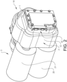
- Fig. 2 shows a perspective view of a powertrain 3 and a transmission assembly 10 for a powertrain 3 of a vehicle 100 according to embodiments of the first and second aspects of the present invention.
- the transmission assembly 10 comprises a control device 1 and a transmission housing 12 for housing a transmission 2.
- the transmission assembly 10 comprises the transmission 2, i.e. the transmission 2 is housed in the transmission housing 12.
- the control device 1 is mountable to the transmission housing 12, and in the embodiment shown in fig. 2 it is mounted to the transmission housing 12.
- the powertrain 3 comprises the transmission assembly 10 and two electric machines 20, 21.
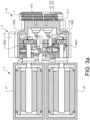
- Figs. 3a-3d show sectional views of the powertrain 3 and/or the transmission assembly 10 as shown in fig. 2 .
- figs. 4a-4b show perspective views of a control device 1 according to the present invention, where in fig. 4b certain details have been omitted to better illustrate the invention.
- control device 1 comprises a transmission mounting surface 4 adapted to face the transmission housing 12 when mounted thereto, and that the transmission housing 12 comprises a corresponding control device mounting surface 121 adapted to face the control device 1 when the control device 1 is mounted to the transmission housing 12.
- the transmission mounting surface 4 comprises at least one groove 41, which groove comprises at least a first and a second step 411, 412, as seen in a direction being perpendicular to the transmission mounting surface 4.
- the second step 412 is deeper than the first step 411.
- the control device mounting surface 121 comprises at least one outwardly extending guiding member 1211, which in the shown embodiments is in the form of a pin, and which is configured to be received in the groove 41.
- the outwardly extending guiding member 1211 and the groove 41 are configured so that the outwardly extending guiding member 1211 can slide in the first step 411 until it reaches the second step 412, whereafter the transmission mounting surface 4 can be moved towards the control device mounting surface 121 or vice versa.
- fig. 3b shows when the outwardly extending guiding member 1211 is provided in the first step 411 of the groove 41 and fig. 3c shows when the outwardly extending guiding member 1211 has reached the second step 412 so that the transmission mounting surface 4 can be moved towards the control device mounting surface 121, or vice versa. Further, fig. 3d shows when the transmission mounting surface 4 has been moved towards the control device mounting surface 121 so that they firmly contact each other.
- the outwardly extending guiding member 1211 and the groove 41 may be configured so that the outwardly extending guiding member 1211 can slide in the first step in a direction which is parallel to, or substantially parallel to, the transmission mounting surface 4.
- This sliding direction may further be perpendicular to, or substantially perpendicular to, an actuation direction A of gear shifting members 16, 17, which will be further described in the below.
- This configuration results in that the transmission mounting surface 4 and the control device mounting surface 121 will not come into contact with each other when actuators 5, 6, 7 of the control device 1 are being connected to corresponding gear shifting members 16, 17 of the transmission 2.
- the gear shifting members 16, 17 are connected to clutch members (not shown) for selectively engaging at least one gear of a set of gears 23 of the transmission 2.
- the clutch members may be configured in any suitable form known to the skilled person, e.g. it may be any one of a slip/friction clutch and/or a no-slip clutch, such as a dog clutch.
- the first step 411 and the outwardly extending guiding member 1211 are configured so that a gap d is present between the transmission mounting surface 4 and the control device mounting surface 121 when the outwardly extending guiding member 1211 is in contact with the first step 411.
- the second step 412 and the outwardly extending guiding member 1211 may be configured so that the transmission mounting surface 4 and the control device mounting surface 121 can firmly contact each other when the outwardly extending guiding member 1211 is provided at the second step 412 in the groove. More specifically, the second step 412 of the groove 41 is preferably deeper than the length of the axial extension of the corresponding outwardly extending guiding member 1211.
- a sealing means (not shown) for sealing between the transmission mounting surface 4 and the control device mounting surface 121 can be protected from being damaged when the control device 1 is being mounted to the transmission housing 12.
- the present invention facilitates connection of the actuators 5, 6, 7 to the gear shifting members 16, 17 when there are restricted possibilities of visually monitoring the assembly operation.
- the control device 1 can be reliably and more easily connected to the transmission housing 12 without the risk of damaging the optional sealing means.
- the present invention provides for an improved blind assembly operation, i.e. an operation where a user/operator is unable to visually follow the assembly operation of the control device 1 to the transmission housing 12.
- the transmission mounting surface 4 may as shown in figs. 4a-4b comprise at least two, three or more of the at least one groove 41, and the control device mounting surface 121 may thereby also comprise at least two, three or more of the at least one outwardly extending guiding member 1211.
- Three grooves/outwardly extending guiding members may be preferred to avoid or eliminate the risk of contact between the two mounting surfaces 41, 121 when the outwardly extending guiding members 1211 are provided at the respective first steps 411 of the grooves 41.
- two, or possibly only one, pair(s) of grooves/ outwardly extending guiding members may suffice.
- three grooves 41 are shown in fig. 4a .
- At least one of the control device mounting surface 121 and the transmission mounting surface 4 may comprise at least one auxiliary guiding member (not shown) for guiding the control device 1 in respect of the transmission housing 12 during assembly so that the outwardly extending guiding member 1211 can be guided to the first step 411 in the groove 41.
- auxiliary guiding member may for example be one or more additional pins.
- the control device 1 and the transmission housing 12 may as shown further comprise a plurality of apertures 413 in which screws 1212 or the like can be provided for attaching the control device 1 to the transmission housing 12.
- the apertures 413 which here extends through the control device 1 and into the transmission housing 12, and the screws 1212 are preferably threaded.
- the control device 1 further comprises the set of actuators 5, 6, 7 which extends from a plane defined by the transmission mounting surface 4, wherein the control device 1 is configured to actuate the gear shifting members 16, 17 by moving the actuators 5, 6, 7 in the actuation direction A.
- the transmission mounting surface 4 encloses an area which the set of actuators 5, 6, 7 are arranged to extend from and/or through.
- the control device mounting surface 121 also encloses an area which the set of actuators 5, 6, 7 are arranged to extend through when the control device 1 is mounted to the transmission housing 12.
- the actuation direction A is perpendicular to, or essentially perpendicular to, the plane defined by the transmission mounting surface 4. It shall here be noted that the actuation direction A may vary as disclosed herein.
- the transmission assembly 10 further comprises the transmission 2.
- the transmission 2 comprises at least one input shaft (not shown) configured to be drivingly connected to at least one propulsion unit 20, 21 of the powertrain 3, at least one output shaft (not shown) configured to be drivingly connected to the at least one driving axle 22 of the vehicle, a set of gears 23 configured for transmission of torque from the at least one input shaft to the at least one output shaft.
- the rotational axis of each input shaft is in the shown embodiments indicated by dash-dotted lines IS1, IS2.
- each electric machine 20, 21 is drivingly connected to one input shaft each, via respective intermediate shafts IMS1, IMS2.
- Each intermediate shaft IMS1, IMS2 is drivingly connected to the respective input shaft via respective meshing gear wheels GW1, GW2.
- the transmission 2 further comprises the set of gear shifting members 16, 17 for selectively engaging at least one gear of the set of gears 23, wherein each one of the actuators 5, 6, 7 is arranged to actuate at least one of the gear shifting members 16, 17 when the control device 1 is mounted to the transmission housing 12.
- the set of actuators 5, 6, 7 and the gear shifting members 16, 17 are connectable and configured so that a coupling direction for coupling the set of actuators 5, 6, 7 to the gear shifting members 16, 17 is parallel to, or essentially parallel to, the control device mounting surface 121 and the transmission mounting surface 4.
- the coupling direction is also perpendicular to, or essentially perpendicular to the actuation direction A.
- each actuator 5, 6, 7 may comprise a connection means 61, 71, which is adapted to be connected to and received in a corresponding receiving means 161, 171 of the gear shifting members 16, 17, whereby the connection means 61, 71 and the receiving means 161, 171 are configured to be coupled by insertion of the connection means 61, 71 into the receiving means 161, 171 in the above mentioned coupling direction.
- each actuator 5, 6, 7 may comprise a receiving means and each gear shifting member 16, 17 may comprise a connection means.
- connection means 61, 71 may be formed as a pin having a waist section 711 with a reduced diameter and an outer head portion 712 provided outside the waist section having a larger diameter, as shown in e.g. figs. 3b-3d .
- the receiving means 161, 171 may be configured so that it can receive the head portion therein and so that when the head portion is received therein, an axial relative movement therebetween is prohibited, or at least very small. Thereby the actuators 5, 6, 7 may efficiently and reliably shift gears during use without for example any risk of unwanted or too much play.
- Fig. 5 shows a flowchart of a method for mounting a control device 1 to a transmission housing 12 of a transmission assembly 10 as e.g. shown in figs. 2-3d .
- the method comprises the following steps:
- a blind assembly operation may be efficiently conducted without the risk of e.g. damaging sealing means which may be provided between the control device mounting surface 121 and the transmission mounting surface 4.
- a compact transmission assembly 10 can be provided, allowing for other components, such as power sources (e.g. batteries) for the electric machines, to be packed nearby the transmission assembly 10.
- the control device 1 may further preferably comprise an electronic control unit (not shown) for controlling the movement of the actuators 5, 6, 7.
- the transmission assembly 10 may be an automated manual transmission or an automatic mechanically engaged transmission (AMT) for a vehicle, such as a truck.
- the electronic control unit may be adapted to receive signals relating to initiation of a gear shifting operation, by moving the actuators 5, 6, 7.
- the signals may e.g. be received from another electronic control unit (ECU) of the vehicle, and/or the signals may be received when a user of the vehicle actuates a gear shifting control device, such as a gear shifting paddle or the like.
- the signals may for example be received via electrical connections EC, and/or the signals may be received by wireless transmission.
Landscapes
- Engineering & Computer Science (AREA)
- General Engineering & Computer Science (AREA)
- Mechanical Engineering (AREA)
- Chemical & Material Sciences (AREA)
- Combustion & Propulsion (AREA)
- Transportation (AREA)
- General Details Of Gearings (AREA)
- Arrangement Of Transmissions (AREA)
- Control Of Transmission Device (AREA)
- Arrangement Or Mounting Of Propulsion Units For Vehicles (AREA)
Claims (15)
- Getriebebaugruppe (10) für einen Antriebsstrang (3) eines Fahrzeugs (100), umfassend eine Steuervorrichtung (1) und ein Getriebegehäuse (12) zum Aufnehmen eines Getriebes (2), wobei die Steuervorrichtung am Getriebegehäuse montiert ist,wobei die Steuervorrichtung eine dem Getriebegehäuse zugewandte Getriebemontagefläche (4) umfasst,wobei das Getriebegehäuse eine entsprechende der Steuervorrichtung zugewandte Steuervorrichtungsmontagefläche (121) umfasst,dadurch gekennzeichnet, dasseine von der Getriebemontagefläche und der Steuervorrichtungsmontagefläche mindestens eine Nut (41) umfasst, wobei die Nut bei Betrachtung in einer Richtung senkrecht zu der einen von der Getriebemontagefläche und der Steuervorrichtungsmontagefläche mindestens eine erste und eine zweite Stufe (411, 412) umfasst, wobei die zweite Stufe tiefer als die erste Stufe ist, unddie andere von der Getriebemontagefläche und der Steuervorrichtungsmontagefläche mindestens ein sich nach außen erstreckendes Führungselement (1211) umfasst, wie etwa einen Stift, das in der Nut aufgenommen ist, und wobei das sich nach außen erstreckende Führungselement und die Nut so konfiguriert sind, dass beim Montieren der Steuervorrichtung (1) an dem Getriebegehäuse (12) das sich nach außen erstreckende Führungselement in der ersten Stufe gleiten kann, bis es die zweite Stufe erreicht, woraufhin die Getriebemontagefläche in Richtung der Steuervorrichtungsmontagefläche bewegt werden kann oder woraufhin die Steuervorrichtungsmontagefläche in Richtung der Getriebemontagefläche bewegt werden kann.
- Getriebebaugruppe nach Anspruch 1, wobei das sich nach außen erstreckende Führungselement und die Nut so konfiguriert sind, dass das sich nach außen erstreckende Führungselement in der ersten Stufe in eine Richtung gleiten kann, die parallel oder im Wesentlichen parallel zu der Steuervorrichtungsmontagefläche und/oder der Getriebemontagefläche verläuft.
- Getriebebaugruppe nach einem der vorhergehenden Ansprüche, wobei die erste Stufe und das sich nach außen erstreckende Führungselement so konfiguriert sind, dass zwischen der Getriebemontagefläche und der Steuervorrichtungsmontagefläche ein Spalt (d) vorhanden ist, wenn das sich nach außen erstreckende Führungselement mit der ersten Stufe in Kontakt steht.
- Getriebebaugruppe nach einem der vorhergehenden Ansprüche, wobei die zweite Stufe und das sich nach außen erstreckende Führungselement so konfiguriert sind, dass die Getriebemontagefläche und die Steuervorrichtungsmontagefläche fest miteinander in Kontakt stehen können, wenn das sich nach außen erstreckende Führungselement an der zweiten Stufe in der Nut bereitgestellt ist.
- Getriebebaugruppe nach einem der vorhergehenden Ansprüche, ferner umfassend eine Dichtungseinrichtung zum Abdichten einer Grenzfläche zwischen der Getriebemontagefläche und der Steuervorrichtungsmontagefläche.
- Getriebebaugruppe nach einem der vorhergehenden Ansprüche, wobei mindestens eine von der Steuervorrichtungsmontagefläche und der Getriebemontagefläche mindestens ein Hilfsführungselement zum Führen der Steuervorrichtung in Bezug auf das Getriebegehäuse während des Montierens umfasst, so dass das sich nach außen erstreckende Führungselement zu der ersten Stufe in der Nut geführt werden kann.
- Getriebebaugruppe nach einem der vorhergehenden Ansprüche, wobei die Steuervorrichtung einen Satz Stellglieder (5, 6, 7) umfasst, die sich von einer durch die Getriebemontagefläche definierten Ebene erstrecken, wobei die Steuervorrichtung dazu konfiguriert ist, Gangschaltelemente (16, 17) der Getriebebaugruppe durch Bewegen der Stellglieder in einer Betätigungsrichtung (A) zu betätigen.
- Getriebebaugruppe nach Anspruch 7, wobei die Betätigungsrichtung einen Winkel α in Bezug auf eine Richtung bildet, die senkrecht zu der durch die Getriebemontagefläche definierten Ebene verläuft, wobei -45° < α < 45°.
- Getriebebaugruppe nach Anspruch 7, wobei die Betätigungsrichtung senkrecht oder im Wesentlichen senkrecht zu der durch die Getriebemontagefläche definierten Ebene verläuft.
- Getriebebaugruppe nach einem der Ansprüche 7 bis 9, ferner umfassend ein Getriebe (2), das mindestens eine Eingangswelle, die dazu konfiguriert ist, mit mindestens einer Antriebseinheit (20, 21) des Antriebsstrangs antreibend verbunden zu sein, mindestens eine Ausgangswelle (50), die dazu konfiguriert ist, mit mindestens einer Antriebsachse (22) des Fahrzeugs antreibend verbunden zu sein, und einen Satz Zahnräder (23) umfasst, die zur Übertragung von Drehmoment von der mindestens einen Eingangswelle auf die mindestens eine Ausgangswelle konfiguriert sind,einen Satz Gangschaltelemente (16, 17) zum selektiven Ineingrifftreten mit mindestens einem Zahnrad des Satzes Zahnräder,wobei jedes der Stellglieder dazu ausgelegt ist, mindestens eines der Gangschaltelemente zu betätigen.
- Getriebebaugruppe nach Anspruch 10, wobei der Satz Stellglieder und die Gangschaltelemente so verbunden und konfiguriert sind, dass eine Kopplungsrichtung zum Koppeln des Satzes Stellglieder an die Gangschaltelemente parallel oder im Wesentlichen parallel zu der Steuervorrichtungsmontagefläche und/oder der Getriebemontagefläche verläuft.
- Getriebebaugruppe nach Anspruch 10 oder 11, wobei sich die Steuervorrichtungsmontagefläche in einer Richtung erstreckt, die senkrecht oder im Wesentlichen senkrecht zu einer axialen Richtung der Eingangswelle ist.
- Antriebsstrang (3) für ein Fahrzeug, umfassend mindestens eine Antriebseinheit (20, 21) und eine Getriebebaugruppe nach einem der Ansprüche 10 bis 12.
- Fahrzeug (100), umfassend eine Getriebebaugruppe nach einem der Ansprüche 10 bis 12 und/oder ein Getriebe nach Anspruch 13.
- Verfahren zum Montieren einer Steuervorrichtung einer Getriebebaugruppe an einem Getriebegehäuse der Getriebebaugruppe nach einem der Ansprüche 1-12, wobei das Verfahren umfasst:- Bewegen (S1) der Steuervorrichtung in Richtung des Getriebegehäuses, so dass sich das sich nach außen erstreckende Führungselement in die erste Stufe in der Nut bewegt,- Bewegen (S2) der Steuervorrichtung, so dass das sich nach außen erstreckende Führungselement in der ersten Stufe gleitet, bis es die zweite Stufe erreicht,- Bewegen (S3) der Steuervorrichtung in Richtung Getriebegehäuse, bis die Getriebemontagefläche die Steuervorrichtungsmontagefläche berührt.
Applications Claiming Priority (1)
| Application Number | Priority Date | Filing Date | Title |
|---|---|---|---|
| PCT/EP2019/082206 WO2021098969A1 (en) | 2019-11-22 | 2019-11-22 | Transmission assembly for a powertrain of a vehicle |
Publications (3)
| Publication Number | Publication Date |
|---|---|
| EP4062085A1 EP4062085A1 (de) | 2022-09-28 |
| EP4062085B1 true EP4062085B1 (de) | 2024-11-20 |
| EP4062085C0 EP4062085C0 (de) | 2024-11-20 |
Family
ID=68654501
Family Applications (1)
| Application Number | Title | Priority Date | Filing Date |
|---|---|---|---|
| EP19808786.8A Active EP4062085B1 (de) | 2019-11-22 | 2019-11-22 | Getriebeanordnung für einen antriebsstrang eines kraftfahrzeuges |
Country Status (4)
| Country | Link |
|---|---|
| US (1) | US11927258B2 (de) |
| EP (1) | EP4062085B1 (de) |
| CN (1) | CN114729689A (de) |
| WO (1) | WO2021098969A1 (de) |
Families Citing this family (1)
| Publication number | Priority date | Publication date | Assignee | Title |
|---|---|---|---|---|
| US11628713B2 (en) * | 2020-06-04 | 2023-04-18 | Rivian Ip Holdings, Llc | Electric vehicle powertrain assembly having nested shafts |
Family Cites Families (8)
| Publication number | Priority date | Publication date | Assignee | Title |
|---|---|---|---|---|
| AU2845901A (en) | 2000-01-10 | 2001-07-24 | Ise Industries Gmbh | Manual gearbox for a passenger motor vehicle |
| DE20015782U1 (de) | 2000-01-10 | 2001-06-07 | Lunke Ventra Automotive GmbH, 58455 Witten | Elektro-hydraulische Steuerung für ein Personenkraftfahrzeug-Getriebe |
| US7219571B2 (en) * | 2004-11-15 | 2007-05-22 | Borgwarner, Inc. | Transmission having an electro-mechanical gear actuation system |
| EP1719935A3 (de) * | 2005-05-07 | 2007-03-14 | LuK Lamellen und Kupplungsbau Beteiligungs KG | Getriebeaktor für eine Kraftfahrzeug-Getriebeeinrichtung, Kraftfahrzeug-Getriebeeinrichtung mit einem solchen Getriebeaktor sowie Kraftfahrzeug-Antriebsstrang mit einer solchen Getriebeeinrichtung |
| ITBO20090143A1 (it) | 2009-03-10 | 2010-09-11 | Cima | Metodo per la modifica della scatola del cambio di un veicolo e scatola del cambio ottenuta da tale modifica. |
| DE102013104552A1 (de) * | 2013-05-03 | 2014-11-06 | Getrag Getriebe- Und Zahnradfabrik Hermann Hagenmeyer Gmbh & Cie Kg | Schaltanordnung für ein Kraftfahrzeuggetriebe |
| EP2881622A1 (de) | 2013-12-05 | 2015-06-10 | Continental Automotive GmbH | Aktuator |
| EP3559516B1 (de) * | 2016-12-23 | 2022-03-02 | Volvo Truck Corporation | Schaltanordnung für das getriebe eines fahrzeugs |
-
2019
- 2019-11-22 CN CN201980102433.9A patent/CN114729689A/zh active Pending
- 2019-11-22 US US17/778,813 patent/US11927258B2/en active Active
- 2019-11-22 EP EP19808786.8A patent/EP4062085B1/de active Active
- 2019-11-22 WO PCT/EP2019/082206 patent/WO2021098969A1/en not_active Ceased
Also Published As
| Publication number | Publication date |
|---|---|
| WO2021098969A1 (en) | 2021-05-27 |
| CN114729689A (zh) | 2022-07-08 |
| EP4062085A1 (de) | 2022-09-28 |
| US11927258B2 (en) | 2024-03-12 |
| EP4062085C0 (de) | 2024-11-20 |
| US20220412446A1 (en) | 2022-12-29 |
Similar Documents
| Publication | Publication Date | Title |
|---|---|---|
| DE102012100865B4 (de) | Antriebsanordnung mit elektrischer Maschine und Kraftfahrzeug mit einer solchen Antriebsanordnung | |
| EP1293373B1 (de) | Antriebsstrang und dessen Zusammenbaumethode | |
| US20200096054A1 (en) | Shift isolation lever system for power-actuated coupling device | |
| US9845856B2 (en) | Powertrain for a road cleaning vehicle | |
| EP3374668B1 (de) | Heckantriebsmodul mit einem hohlrad-trenn- und synchronisationsverriegelungsmechanismus | |
| EP3442820B1 (de) | Fahrzeugantriebsstrangsystem | |
| WO2021198878A1 (en) | Drive unit for automotive vehicle | |
| KR101360381B1 (ko) | 구동 장치의 결합해제 | |
| US11927258B2 (en) | Transmission assembly for a powertrain of a vehicle | |
| EP4055301B1 (de) | Getriebeanordnung für ein fahrzeug | |
| EP3124357A1 (de) | Einheit für fahrzeuglenksystem | |
| EP4055302B1 (de) | Getriebeanordnung für ein fahrzeug | |
| EP4578683A1 (de) | Motorantriebsvorrichtung | |
| US6679348B2 (en) | Vehicular two-wheel/four-wheel drive switching device | |
| US9222570B2 (en) | Power transmission apparatus | |
| US10704611B2 (en) | Torque converter lockup clutch backing plate | |
| US12110928B2 (en) | Dog clutch assembly, powertrain, and motor vehicle | |
| EP0727332A1 (de) | Parallelhybridantrieb für ein Kraftfahrzeug | |
| WO2021098970A1 (en) | A control device, a transmission assembly and a powertrain | |
| US20260002587A1 (en) | A gear shifting device, a transmission and a method for assembling a transmission | |
| KR101562469B1 (ko) | 사륜구동 차량용 부변속기 | |
| JPH09269043A (ja) | ディファレンシャルギヤ装置 | |
| JPH0218850Y2 (de) |
Legal Events
| Date | Code | Title | Description |
|---|---|---|---|
| STAA | Information on the status of an ep patent application or granted ep patent |
Free format text: STATUS: UNKNOWN |
|
| STAA | Information on the status of an ep patent application or granted ep patent |
Free format text: STATUS: THE INTERNATIONAL PUBLICATION HAS BEEN MADE |
|
| PUAI | Public reference made under article 153(3) epc to a published international application that has entered the european phase |
Free format text: ORIGINAL CODE: 0009012 |
|
| STAA | Information on the status of an ep patent application or granted ep patent |
Free format text: STATUS: REQUEST FOR EXAMINATION WAS MADE |
|
| 17P | Request for examination filed |
Effective date: 20220531 |
|
| AK | Designated contracting states |
Kind code of ref document: A1 Designated state(s): AL AT BE BG CH CY CZ DE DK EE ES FI FR GB GR HR HU IE IS IT LI LT LU LV MC MK MT NL NO PL PT RO RS SE SI SK SM TR |
|
| DAV | Request for validation of the european patent (deleted) | ||
| DAX | Request for extension of the european patent (deleted) | ||
| STAA | Information on the status of an ep patent application or granted ep patent |
Free format text: STATUS: EXAMINATION IS IN PROGRESS |
|
| 17Q | First examination report despatched |
Effective date: 20231106 |
|
| GRAP | Despatch of communication of intention to grant a patent |
Free format text: ORIGINAL CODE: EPIDOSNIGR1 |
|
| STAA | Information on the status of an ep patent application or granted ep patent |
Free format text: STATUS: GRANT OF PATENT IS INTENDED |
|
| RIC1 | Information provided on ipc code assigned before grant |
Ipc: B60K 1/02 20060101ALN20240417BHEP Ipc: B60K 23/00 20060101ALI20240417BHEP Ipc: F16H 61/688 20060101ALI20240417BHEP Ipc: F16H 3/093 20060101ALI20240417BHEP Ipc: F16H 63/30 20060101ALI20240417BHEP Ipc: F16H 63/24 20060101ALI20240417BHEP Ipc: F16H 3/00 20060101ALI20240417BHEP Ipc: F16H 57/00 20120101ALI20240417BHEP Ipc: F16H 61/00 20060101AFI20240417BHEP |
|
| INTG | Intention to grant announced |
Effective date: 20240513 |
|
| GRAJ | Information related to disapproval of communication of intention to grant by the applicant or resumption of examination proceedings by the epo deleted |
Free format text: ORIGINAL CODE: EPIDOSDIGR1 |
|
| STAA | Information on the status of an ep patent application or granted ep patent |
Free format text: STATUS: EXAMINATION IS IN PROGRESS |
|
| GRAP | Despatch of communication of intention to grant a patent |
Free format text: ORIGINAL CODE: EPIDOSNIGR1 |
|
| STAA | Information on the status of an ep patent application or granted ep patent |
Free format text: STATUS: GRANT OF PATENT IS INTENDED |
|
| INTC | Intention to grant announced (deleted) | ||
| GRAS | Grant fee paid |
Free format text: ORIGINAL CODE: EPIDOSNIGR3 |
|
| RIC1 | Information provided on ipc code assigned before grant |
Ipc: B60K 1/02 20060101ALN20240911BHEP Ipc: B60K 23/00 20060101ALI20240911BHEP Ipc: F16H 61/688 20060101ALI20240911BHEP Ipc: F16H 3/093 20060101ALI20240911BHEP Ipc: F16H 63/30 20060101ALI20240911BHEP Ipc: F16H 63/24 20060101ALI20240911BHEP Ipc: F16H 3/00 20060101ALI20240911BHEP Ipc: F16H 57/00 20120101ALI20240911BHEP Ipc: F16H 61/00 20060101AFI20240911BHEP |
|
| GRAA | (expected) grant |
Free format text: ORIGINAL CODE: 0009210 |
|
| STAA | Information on the status of an ep patent application or granted ep patent |
Free format text: STATUS: THE PATENT HAS BEEN GRANTED |
|
| INTG | Intention to grant announced |
Effective date: 20241008 |
|
| AK | Designated contracting states |
Kind code of ref document: B1 Designated state(s): AL AT BE BG CH CY CZ DE DK EE ES FI FR GB GR HR HU IE IS IT LI LT LU LV MC MK MT NL NO PL PT RO RS SE SI SK SM TR |
|
| REG | Reference to a national code |
Ref country code: GB Ref legal event code: FG4D |
|
| REG | Reference to a national code |
Ref country code: CH Ref legal event code: EP |
|
| REG | Reference to a national code |
Ref country code: DE Ref legal event code: R096 Ref document number: 602019062304 Country of ref document: DE |
|
| REG | Reference to a national code |
Ref country code: IE Ref legal event code: FG4D |
|
| U01 | Request for unitary effect filed |
Effective date: 20241209 |
|
| U07 | Unitary effect registered |
Designated state(s): AT BE BG DE DK EE FI FR IT LT LU LV MT NL PT RO SE SI Effective date: 20241219 |
|
| U1N | Appointed representative for the unitary patent procedure changed after the registration of the unitary effect |
Representative=s name: KRANSELL & WENNBORG KB; SE |
|
| U20 | Renewal fee for the european patent with unitary effect paid |
Year of fee payment: 6 Effective date: 20250221 |
|
| PG25 | Lapsed in a contracting state [announced via postgrant information from national office to epo] |
Ref country code: HR Free format text: LAPSE BECAUSE OF FAILURE TO SUBMIT A TRANSLATION OF THE DESCRIPTION OR TO PAY THE FEE WITHIN THE PRESCRIBED TIME-LIMIT Effective date: 20241120 Ref country code: IS Free format text: LAPSE BECAUSE OF FAILURE TO SUBMIT A TRANSLATION OF THE DESCRIPTION OR TO PAY THE FEE WITHIN THE PRESCRIBED TIME-LIMIT Effective date: 20250320 |
|
| PG25 | Lapsed in a contracting state [announced via postgrant information from national office to epo] |
Ref country code: ES Free format text: LAPSE BECAUSE OF FAILURE TO SUBMIT A TRANSLATION OF THE DESCRIPTION OR TO PAY THE FEE WITHIN THE PRESCRIBED TIME-LIMIT Effective date: 20241120 |
|
| PG25 | Lapsed in a contracting state [announced via postgrant information from national office to epo] |
Ref country code: NO Free format text: LAPSE BECAUSE OF FAILURE TO SUBMIT A TRANSLATION OF THE DESCRIPTION OR TO PAY THE FEE WITHIN THE PRESCRIBED TIME-LIMIT Effective date: 20250220 |
|
| PG25 | Lapsed in a contracting state [announced via postgrant information from national office to epo] |
Ref country code: GR Free format text: LAPSE BECAUSE OF FAILURE TO SUBMIT A TRANSLATION OF THE DESCRIPTION OR TO PAY THE FEE WITHIN THE PRESCRIBED TIME-LIMIT Effective date: 20250221 |
|
| PG25 | Lapsed in a contracting state [announced via postgrant information from national office to epo] |
Ref country code: PL Free format text: LAPSE BECAUSE OF FAILURE TO SUBMIT A TRANSLATION OF THE DESCRIPTION OR TO PAY THE FEE WITHIN THE PRESCRIBED TIME-LIMIT Effective date: 20241120 |
|
| PG25 | Lapsed in a contracting state [announced via postgrant information from national office to epo] |
Ref country code: RS Free format text: LAPSE BECAUSE OF FAILURE TO SUBMIT A TRANSLATION OF THE DESCRIPTION OR TO PAY THE FEE WITHIN THE PRESCRIBED TIME-LIMIT Effective date: 20250220 |
|
| REG | Reference to a national code |
Ref country code: CH Ref legal event code: PL |
|
| PG25 | Lapsed in a contracting state [announced via postgrant information from national office to epo] |
Ref country code: SM Free format text: LAPSE BECAUSE OF FAILURE TO SUBMIT A TRANSLATION OF THE DESCRIPTION OR TO PAY THE FEE WITHIN THE PRESCRIBED TIME-LIMIT Effective date: 20241120 |
|
| REG | Reference to a national code |
Ref country code: CH Ref legal event code: PL |
|
| PG25 | Lapsed in a contracting state [announced via postgrant information from national office to epo] |
Ref country code: CH Free format text: LAPSE BECAUSE OF NON-PAYMENT OF DUE FEES Effective date: 20241130 |
|
| PG25 | Lapsed in a contracting state [announced via postgrant information from national office to epo] |
Ref country code: SK Free format text: LAPSE BECAUSE OF FAILURE TO SUBMIT A TRANSLATION OF THE DESCRIPTION OR TO PAY THE FEE WITHIN THE PRESCRIBED TIME-LIMIT Effective date: 20241120 |
|
| PG25 | Lapsed in a contracting state [announced via postgrant information from national office to epo] |
Ref country code: CZ Free format text: LAPSE BECAUSE OF FAILURE TO SUBMIT A TRANSLATION OF THE DESCRIPTION OR TO PAY THE FEE WITHIN THE PRESCRIBED TIME-LIMIT Effective date: 20241120 |
|
| PG25 | Lapsed in a contracting state [announced via postgrant information from national office to epo] |
Ref country code: MC Free format text: LAPSE BECAUSE OF FAILURE TO SUBMIT A TRANSLATION OF THE DESCRIPTION OR TO PAY THE FEE WITHIN THE PRESCRIBED TIME-LIMIT Effective date: 20241120 |
|
| PLBE | No opposition filed within time limit |
Free format text: ORIGINAL CODE: 0009261 |
|
| STAA | Information on the status of an ep patent application or granted ep patent |
Free format text: STATUS: NO OPPOSITION FILED WITHIN TIME LIMIT |
|
| 26N | No opposition filed |
Effective date: 20250821 |
|
| PG25 | Lapsed in a contracting state [announced via postgrant information from national office to epo] |
Ref country code: IE Free format text: LAPSE BECAUSE OF NON-PAYMENT OF DUE FEES Effective date: 20241122 |
|
| GBPC | Gb: european patent ceased through non-payment of renewal fee |
Effective date: 20250220 |
|
| U20 | Renewal fee for the european patent with unitary effect paid |
Year of fee payment: 7 Effective date: 20251126 |
|
| PG25 | Lapsed in a contracting state [announced via postgrant information from national office to epo] |
Ref country code: GB Free format text: LAPSE BECAUSE OF NON-PAYMENT OF DUE FEES Effective date: 20250220 |
|
| PG25 | Lapsed in a contracting state [announced via postgrant information from national office to epo] |
Ref country code: HU Free format text: LAPSE BECAUSE OF FAILURE TO SUBMIT A TRANSLATION OF THE DESCRIPTION OR TO PAY THE FEE WITHIN THE PRESCRIBED TIME-LIMIT; INVALID AB INITIO Effective date: 20191122 |
|
| PG25 | Lapsed in a contracting state [announced via postgrant information from national office to epo] |
Ref country code: CY Free format text: LAPSE BECAUSE OF FAILURE TO SUBMIT A TRANSLATION OF THE DESCRIPTION OR TO PAY THE FEE WITHIN THE PRESCRIBED TIME-LIMIT; INVALID AB INITIO Effective date: 20191122 |