EP4062087B1 - Soupape d'arrêt à double mouvement - Google Patents
Soupape d'arrêt à double mouvement Download PDFInfo
- Publication number
- EP4062087B1 EP4062087B1 EP19953061.9A EP19953061A EP4062087B1 EP 4062087 B1 EP4062087 B1 EP 4062087B1 EP 19953061 A EP19953061 A EP 19953061A EP 4062087 B1 EP4062087 B1 EP 4062087B1
- Authority
- EP
- European Patent Office
- Prior art keywords
- shaft
- valve
- valve disk
- driver ring
- closed position
- Prior art date
- Legal status (The legal status is an assumption and is not a legal conclusion. Google has not performed a legal analysis and makes no representation as to the accuracy of the status listed.)
- Active
Links
Images




Classifications
-
- F—MECHANICAL ENGINEERING; LIGHTING; HEATING; WEAPONS; BLASTING
- F16—ENGINEERING ELEMENTS AND UNITS; GENERAL MEASURES FOR PRODUCING AND MAINTAINING EFFECTIVE FUNCTIONING OF MACHINES OR INSTALLATIONS; THERMAL INSULATION IN GENERAL
- F16K—VALVES; TAPS; COCKS; ACTUATING-FLOATS; DEVICES FOR VENTING OR AERATING
- F16K1/00—Lift valves or globe valves, i.e. cut-off apparatus with closure members having at least a component of their opening and closing motion perpendicular to the closing faces
- F16K1/16—Lift valves or globe valves, i.e. cut-off apparatus with closure members having at least a component of their opening and closing motion perpendicular to the closing faces with pivoted closure-members
- F16K1/18—Lift valves or globe valves, i.e. cut-off apparatus with closure members having at least a component of their opening and closing motion perpendicular to the closing faces with pivoted closure-members with pivoted discs or flaps
- F16K1/20—Lift valves or globe valves, i.e. cut-off apparatus with closure members having at least a component of their opening and closing motion perpendicular to the closing faces with pivoted closure-members with pivoted discs or flaps with axis of rotation arranged externally of valve member
- F16K1/2007—Lift valves or globe valves, i.e. cut-off apparatus with closure members having at least a component of their opening and closing motion perpendicular to the closing faces with pivoted closure-members with pivoted discs or flaps with axis of rotation arranged externally of valve member specially adapted operating means therefor
-
- F—MECHANICAL ENGINEERING; LIGHTING; HEATING; WEAPONS; BLASTING
- F16—ENGINEERING ELEMENTS AND UNITS; GENERAL MEASURES FOR PRODUCING AND MAINTAINING EFFECTIVE FUNCTIONING OF MACHINES OR INSTALLATIONS; THERMAL INSULATION IN GENERAL
- F16K—VALVES; TAPS; COCKS; ACTUATING-FLOATS; DEVICES FOR VENTING OR AERATING
- F16K1/00—Lift valves or globe valves, i.e. cut-off apparatus with closure members having at least a component of their opening and closing motion perpendicular to the closing faces
- F16K1/16—Lift valves or globe valves, i.e. cut-off apparatus with closure members having at least a component of their opening and closing motion perpendicular to the closing faces with pivoted closure-members
- F16K1/18—Lift valves or globe valves, i.e. cut-off apparatus with closure members having at least a component of their opening and closing motion perpendicular to the closing faces with pivoted closure-members with pivoted discs or flaps
- F16K1/22—Lift valves or globe valves, i.e. cut-off apparatus with closure members having at least a component of their opening and closing motion perpendicular to the closing faces with pivoted closure-members with pivoted discs or flaps with axis of rotation crossing the valve member, e.g. butterfly valves
- F16K1/226—Shaping or arrangements of the sealing
-
- F—MECHANICAL ENGINEERING; LIGHTING; HEATING; WEAPONS; BLASTING
- F16—ENGINEERING ELEMENTS AND UNITS; GENERAL MEASURES FOR PRODUCING AND MAINTAINING EFFECTIVE FUNCTIONING OF MACHINES OR INSTALLATIONS; THERMAL INSULATION IN GENERAL
- F16K—VALVES; TAPS; COCKS; ACTUATING-FLOATS; DEVICES FOR VENTING OR AERATING
- F16K1/00—Lift valves or globe valves, i.e. cut-off apparatus with closure members having at least a component of their opening and closing motion perpendicular to the closing faces
- F16K1/24—Lift valves or globe valves, i.e. cut-off apparatus with closure members having at least a component of their opening and closing motion perpendicular to the closing faces with valve members that, on opening of the valve, are initially lifted from the seat and next are turned around an axis parallel to the seat
-
- F—MECHANICAL ENGINEERING; LIGHTING; HEATING; WEAPONS; BLASTING
- F16—ENGINEERING ELEMENTS AND UNITS; GENERAL MEASURES FOR PRODUCING AND MAINTAINING EFFECTIVE FUNCTIONING OF MACHINES OR INSTALLATIONS; THERMAL INSULATION IN GENERAL
- F16K—VALVES; TAPS; COCKS; ACTUATING-FLOATS; DEVICES FOR VENTING OR AERATING
- F16K31/00—Actuating devices; Operating means; Releasing devices
- F16K31/44—Mechanical actuating means
- F16K31/52—Mechanical actuating means with crank, eccentric, or cam
- F16K31/524—Mechanical actuating means with crank, eccentric, or cam with a cam
-
- F—MECHANICAL ENGINEERING; LIGHTING; HEATING; WEAPONS; BLASTING
- F16—ENGINEERING ELEMENTS AND UNITS; GENERAL MEASURES FOR PRODUCING AND MAINTAINING EFFECTIVE FUNCTIONING OF MACHINES OR INSTALLATIONS; THERMAL INSULATION IN GENERAL
- F16K—VALVES; TAPS; COCKS; ACTUATING-FLOATS; DEVICES FOR VENTING OR AERATING
- F16K35/00—Means to prevent accidental or unauthorised actuation
- F16K35/06—Means to prevent accidental or unauthorised actuation using a removable actuating or locking member, e.g. a key
Definitions
- Ball valves are quarter-turn valves that often use a hollow, perforated, and pivoting ball to control flow through the valve assembly. When the ball's hole is in line with a flow path, the valve is open and when the hole is pivoted 90-degrees, the valve is closed. Ball valves are often used in shutoff and control applications and may be preferred over gates and globe valves because of their durability, reliability, and ability to withstand high pressures and temperatures.
- Butterfly valves are similar to ball valves.
- a butterfly valve includes a disk (a "butterfly") positioned in the center of the flow path with a shaft passing through the disk to an actuator outside of the valve. Rotating the actuator causes the disk to turn between parallel and perpendicular positions in the flow path. Unlike a ball valve, the disk is always present within the flow path, which induces a decrease in pressure even when the valve is in the open position. In operation, the valve can be changed between fully open and fully closed by rotating the disk by a quarter turn. The butterfly valve may also be opened incrementally to throttle flow.
- Some ball or butterfly valve assemblies may include a solid seal covered with or made from a reduced-friction material that is urged against the metal ball or butterfly disk as installed.
- US 3498583 A describes a compound movement butterfly-type valve member which is rotated to move between an open position, wherein the disc-shaped valve member is disposed parallel to the flow and a flow-traversing position, and a flow-traversing position.
- JP H10238637 A describes a valve device in which a disk bush is integratedly connected to a boss part that is arranged between a slide key provided in a rod and a boss part of a valve element.
- US 3697042 A describes a rotatable valve structure, such as a butterfly valve, wherein the shaft is movable axially, with a camming surface on the shaft engaging a complementary camming surface on the disc.
- the present disclosure generally describes dual motion shutoff valve assemblies.
- the sequencing drive assembly may be configured to cause the valve disk to disengage the first gasket and retract linearly from the first gasket during a rotation of the shaft from the closed position to the retracted position; subsequently cause the valve disk to move rotationally from the retracted position to the open position; cause the valve disk to move rotationally from the open position to the retracted position; and subsequently cause the valve disk to extend linearly toward the first gasket and to engage the first gasket during another rotation of the shaft from the retracted position to the closed position.
- the sequencing drive assembly may also be configured to from the closed position, actuate an about 60-degree rotation of the shaft during which the valve disk is transitioned into the retracted position from the closed position and actuate a further about 90-degree rotation of the shaft during which the valve disk is transitioned into the open position from the retracted position.
- the sequencing drive assembly may also be configured to from the open position, actuate an about 90-degree rotation of the shaft during which the valve disk is transitioned into the retracted position from the open position and actuate a further about 60-degree rotation of the shaft during which the valve disk is transitioned into the closed position from the retracted position.
- the pair of interlocking rollers may be configured to engage the outer driver ring and the retaining housing together by sliding into the two depressions at opposite locations of the inside surface of the sidewall of the retaining housing during a rotation of the shaft from the closed position to the retracted position or from the retracted position to the closed position of the valve assembly effective to cause the valve disk to remain angularly stationary during the rotation of the shaft; and engage the inner driver ring and the outer driver ring together by sliding into the two depressions at opposite locations of the outside surface of the sidewall of the inner driver ring during another rotation of the shaft from the retracted position to the open position or from the open position to the retracted position of the valve assembly effective to cause the valve disk to rotate during the other rotation of the shaft.
- the sequencing drive assembly may further include three guide pins that extend from a bottom surface of the outer driver ring, the three guide pins configured to engage three corresponding apertures in a top bracket coupled to the valve disk.
- the three corresponding apertures in the top bracket may be shaped to allow the three guide pins to move freely during a rotation of the shaft from the closed position to the retracted position or from the retracted position to the closed position of the valve assembly effective to cause the valve disk to remain angularly stationary during the rotation of the shaft, or cause the top bracket to move during a rotation of the shaft from the retracted position to the open position or from the open position to the retracted position of the valve assembly effective to cause the valve disk to rotate during the rotation of the shaft.
- the valve disk may include a top bracket that extends from an upper portion of the spherical surface portion of the valve disk and includes a first aperture for the shaft to pass through, where an upper cammed portion of the shaft is configured to slidably engage into the first aperture of the top bracket; and a bottom bracket that extends from a lower portion of the spherical surface portion of the valve disk and includes a second aperture for the shaft to pass through, where a lower cammed portion of the shaft is configured to slidably engage into the second aperture of the bottom bracket.
- the valve assembly may further include a top valve link movably coupled to the top bracket; a bottom shaft movably coupled to the bottom bracket; and a bottom valve link movably coupled to the bottom bracket, where the top valve link includes a ball bearing to hold the shaft and a third aperture adapted to receive a locking pin that is inserted through the top bracket to secure the top valve link to the top bracket and the bottom valve link includes another ball bearing to hold the shaft and a fourth aperture adapted to receive another locking pin that is inserted through the bottom bracket to secure the bottom valve link to the bottom bracket.
- a dual motion shutoff valve (not claimed as such) assembly may include a valve body having an inner wall, a first port defined by a first portion of the inner wall, a second port defined by a second portion of the inner wall, and a controllable flow path defined by a third portion of the inner wall between the first port and the second port; a first gasket disposed about the first port; a valve disk disposed in the controllable flow path, where the valve disk comprises a spherical surface portion configured to selectively engage the first gasket in a closed position of the valve assembly effective to form a seal thereon; and a top shaft coupled to an upper portion of the valve disk, wherein the top shaft is configured to actuate a position of the valve disk between the closed position and an open position such that the valve disk is placed in a retracted position relative to the first gasket when the top shaft is moved to the open position from the closed position or to the closed position from the open position.
- valve assembly may further include a bottom shaft coupled to a lower portion of the valve disk, and the valve disk may further include a bottom bracket that extends from a lower portion of the spherical surface portion of the valve disk and includes a first aperture for the bottom shaft to slidably engage.
- the valve assembly may further include a sequencing drive assembly coupled to the top shaft and the valve disk, where the sequencing drive assembly is configured to actuate a position of the top shaft between the open position and the closed position.
- the sequencing drive assembly may be configured to cause the valve disk to disengage the first gasket and retract linearly from the first gasket during a rotation of the top shaft from the closed position to the retracted position; subsequently cause the valve disk to move rotationally from the retracted position to the open position; cause the valve disk to move rotationally from the open position to the retracted position; and subsequently cause the valve disk to extend linearly toward the first gasket and to engage the first gasket during another rotation of the top shaft from the retracted position to the closed position.
- the sequencing drive assembly may include an inner driver ring configured to surround the top shaft, the inner driver ring having a sidewall and two depressions about opposite locations on an outside surface of the sidewall of the inner driver ring; an outer driver ring configured to surround the inner driver ring, the outer driver ring having a sidewall and two apertures about opposite locations of the sidewall of the outer driver ring; a retaining housing configured to surround the inner driver ring and the outer driver ring, the retaining housing having a sidewall and two depressions about opposite locations of an inside surface of the sidewall of the retaining housing; and a pair of interlocking rollers configured to slidably engage in the two apertures about the opposite locations of the sidewall of the outer driver ring.
- the pair of interlocking rollers may be configured to engage the outer driver ring and the retaining housing together by sliding into the two depressions at opposite locations of the inside surface of the sidewall of the retaining housing during a rotation of the top shaft from the closed position to the retracted position or from the retracted position to the closed position of the valve assembly effective to cause the valve disk to remain angularly stationary during the rotation of the top shaft; and engage the inner driver ring and the outer driver ring together by sliding into the two depressions at opposite locations of the outside surface of the sidewall of the inner driver ring during another rotation of the top shaft from the retracted position to the open position or from the open position to the retracted position of the valve assembly effective to cause the valve disk to rotate during the other rotation of the top shaft.
- the sequencing drive assembly may further include three guide pins that extend from a bottom surface of the retaining housing, the three guide pins configured to engage three corresponding apertures in a top bracket coupled to the valve disk.
- the three corresponding apertures in the top bracket may be shaped to allow the three guide pins to move freely during a rotation of the top shaft from the closed position to the retracted position or from the retracted position to the closed position of the valve assembly effective to cause the valve disk to remain angularly stationary during the rotation of the top shaft, or cause the top bracket to move during a rotation of the top shaft from the retracted position to the open position or from the open position to the retracted position of the valve assembly effective to cause the valve disk to rotate during the rotation of the top shaft.
- the valve assembly may also include a bottom shaft coupled to a lower portion of the valve disk; a top valve link movably coupled to a top bracket that extends from an upper portion of the spherical surface portion of the valve disk; and a bottom bracket movably coupled to a bottom shaft that extends from a lower portion of the spherical surface portion of the valve disk.
- a dual motion shutoff valve assembly may include a valve body having an inner wall, a first port defined by a first portion of the inner wall, a second port defined by a second portion of the inner wall, and a controllable flow path that defined by a third portion of the inner wall between the first port and the second port; a first gasket disposed about the first port; a second gasket disposed about the second port; a valve disk disposed in the controllable flow path, where the valve disk includes a spherical surface portion configured to selectively engage the first gasket in a closed position of the valve assembly effective to form a seal thereon; an eccentric shaft coupled to the valve disk, where the shaft is configured to actuate a position of the valve disk between the closed position and an open position; and a sequencing drive assembly coupled to the shaft and the valve disk, where the sequencing drive assembly is configured to actuate a position of the shaft such that the valve disk is placed in a retracted position relative to the first gasket when the
- the sequencing drive assembly may be configured to cause the valve disk to disengage the first gasket and retract linearly from the first gasket during a rotation of the shaft from the closed position to the retracted position; subsequently cause the valve disk to move rotationally from the retracted position to the open position; cause the valve disk to move rotationally from the open position to the retracted position; and subsequently cause the valve disk to extend linearly toward the first gasket and to engage the first gasket during another rotation of the shaft from the retracted position to the closed position.
- the shaft may include a top shaft coupled to an upper portion of the valve disk, and a bottom shaft coupled to a lower portion of the valve disk.
- the valve disk may include a top bracket that extends from the upper portion of the valve disk and includes a first aperture for the top shaft to pass through, where an upper cammed portion of the top shaft is configured to slidably engage into the first aperture of the top bracket, and a bottom bracket that extends from the lower portion of the valve disk and includes a second aperture for the bottom shaft to pass through, where a lower cammed portion of the lower shaft is configured to slidably engage into the second aperture of the bottom bracket.
- the sequencing drive assembly may further include three guide pins that extend from a bottom surface of an outer driver ring, the three guide pins configured to engage three corresponding apertures in the top bracket coupled to the valve disk.
- the three corresponding apertures in the top bracket may be shaped to allow the three guide pins to move freely during a rotation of the top shaft from the closed position to the retracted position or from the retracted position to the closed position of the valve assembly effective to cause the valve disk to remain angularly stationary during the rotation of the top shaft, or cause the top bracket to move during another rotation of the top shaft from the retracted position to the open position or from the open position to the retracted position of the valve assembly effective to cause the valve disk to rotate during the other rotation of the top shaft.
- the valve assembly may also include a top valve link movably coupled to the top bracket; and a bottom shaft movably coupled to the bottom bracket.
- the method may further include forming the sequencing drive assembly to cause the valve disk to disengage the first gasket and retract linearly from the first gasket during a rotation of the shaft from the closed position to the retracted position, and subsequently to cause the valve disk to move rotationally from the retracted position to the open position; and cause the valve disk to move rotationally from the open position to the retracted position, and subsequently cause the valve disk to extend linearly toward the first gasket and to engage the first gasket during another rotation of the shaft from the retracted position to the closed position.
- forming the outer driver ring, the retaining housing, and the pair of interlocking rollers may include arranging the pair of interlocking rollers to engage the outer driver ring and the retaining housing together by sliding into the two depressions at opposite locations of the inside surface of the sidewall of the retaining housing during a rotation of the shaft from the closed position to the retracted position or from the retracted position to the closed position of the valve assembly effective to cause the valve disk to remain angularly stationary during the rotation of the shaft.
- Forming the inner driver ring, the outer driver ring, and the pair of interlocking rollers may include arranging the pair of interlocking rollers to engage the inner driver ring and the outer driver ring together by sliding into the two depressions at opposite locations of the outside surface of the sidewall of the inner driver ring during a rotation of the shaft from the retracted position to the open position or from the open position to the retracted position of the valve assembly effective to cause the valve disk to rotate during the rotation of the shaft.
- Forming the shaft to actuate the position of the valve disk between the closed position and the open position may include forming a top shaft to actuate the position of the valve disk between the closed position and the open position; coupling the top shaft to an upper portion of the valve disk in an offset manner such that the valve disk is placed in a retracted position relative to the first gasket when the top shaft is moved to the open position from the closed position or to the closed position from the open position; forming a bottom shaft coupled to a lower portion of the valve disk; and coupling the bottom shaft to the lower portion of the valve disk.
- This disclosure is generally drawn, inter alia, to methods, apparatus, systems and/or devices associated with dual motion shutoff valve assemblies.
- the valve assemblies include a sequencing drive mechanism and an eccentric shaft mechanism operable to linearly retract the valve disk from a gasket surface to effectively reduce scratching and friction of the gasket surface during valve opening and closing operations.
- the sequencing drive may include two interlocking concentric driver rings, a retaining housing, and roller lock pins. Three guided pins of the sequencing drive may be configured to prevent the valve from rotating, while also causing the valve to retract linearly from the gasket surface via the eccentric shaft.
- an inner driver of the sequencing drive may allow the roller lock pins to move and engage the outer driver, which in turn may engage the valve disk to the shaft and rotate along with the shaft, which may be a single or dual shaft.
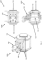
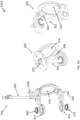
- FIG. 1 illustrates different cutaway views of a valve assembly with dual motion shutoff capability, arranged in accordance with at least some embodiments described herein.
- Diagram 100 includes three views, 100A, 100B, and 100C of an example dual motion shutoff valve.
- View 100A is an isometric view of the valve assembly with a valve body 102, valve ports 104, sequencing drive assembly 106, and sequencing drive interface 108.
- View 100B is a top view of the valve assembly with valve body 102 and valve ports 104.
- View 100C is a side cross-sectional view of the valve assembly with the valve ports 104, sequencing drive assembly 106, valve disk 110, and shaft 112.
- the valve body 102 may include an inner wall, a first portion of which may define a first one of the valve ports 104 and a second portion of the inner wall may define a second one of the valve ports 104.
- the valve ports 104 may be designated as ingress and egress ports.
- the inner wall of the valve body and the valve ports 104 may define a controllable flow path that extends along the inner wall between the first one of the valve ports 104 and the second one of the valve ports 104.
- Flow of liquids or gases through the controllable flow path may be controlled by the valve disk 110, which may be rotated by the shaft 112 between an open position (aligned with the controllable flow path) and closed position (in contact with one of the valve ports and perpendicular to the controllable flow path).
- a spherical surface portion of the valve disk 110 may be adapted to seal one of the valve ports 104 in a closed position of the valve assembly, for example, by engaging a corresponding gasket to affect a seal or block to the corresponding port.
- the spherical surface portion of the valve disk 110 may be considerably flat, meaning the surface portion may include small irregularities or may be angled without affecting its functionality.
- a valve assembly may employ an eccentric shaft and a sequencing drive mechanism to affect dual motion shutoff (and opening).
- a partial or hemispherical rotatable member may be used instead of the valve disk 110.
- the hemispherical shape of the rotatable member may be formed as a half of a sphere with a center portion substantially hollowed out on one side of the sphere.
- the shape of the rotatable member with the hemispherical shape may be coupled to the shaft 112 in an offset position to facilitate improved volume of flow for fluids or gases through the controllable flow path.
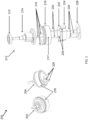
- FIG. 2 illustrates exploded assembly views of a sequencing drive mechanism for a dual motion shutoff valve assembly, arranged in accordance with at least some embodiments described herein.
- Diagram 200 includes three views, 202, 204, and 210, of an example sequencing drive mechanism.
- Views 202 and 204 are perspective views of the sequence driving mechanism from different angles showing retaining housing 218 and guide pins 226.
- View 210 shows an exploded assembly view of the sequencing drive assembly, which includes ball bearing 212, inner driver ring 214, first set of interlocking dowel pins 216, retaining housing 218, second set of interlocking dowel pins 220, outer driver ring 222, interlocking rollers 224, guide pins 226, and washer 228.
- the retaining housing 218 may have a disk-shaped form with a round sidewall 217.
- the disk-shaped form or the round form may deviate from a circle without affecting their configuration or functionality.
- the retaining housing 218 may contain the outer driver ring 222 that fits inside a cavity formed by the sidewall 217.
- the outer driver ring 222 may be fitted around the inner driver ring 214.
- the inner driver ring 214 may be engaged together with the eccentric shaft.
- the interlocking rollers 224 may be located about 180 degrees apart and fit in cavities 225 in the outer driver ring 222.
- the interlocking rollers 224 may be effective to engage combinations of the inner driver ring 214, the outer driver ring 222, and the retaining housing 218 in different phases of valve opening and closing operations (e.g., retraction, rotation).
- the outer driver ring 222 may include three pressed fit guide pins 226, which may fit onto the slots of valve disk (shown in FIG. 5A and 5B ).
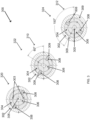
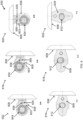
- FIG. 3 illustrates various cross-sectional top views of an example sequencing drive mechanism where the disk of the valve assembly is oriented in different positions during operation of the mechanism, arranged in accordance with at least some embodiments described herein.
- Diagram 300 illustrates three cross-sectional top views, 320, 322, and 324 of an example sequencing drive mechanism.
- View 320 illustrates a closed position with retaining housing 302, outer driver ring 304, inner driver ring 306, depressions 303 located about an outer surface of the inner driver ring 306, shaft 305, and interlocking rollers 308.
- View 322 illustrates a retracted position (e.g., about a 60-degree rotation) 310 with interlocking rollers 308 moved to a position out of the depressions 309 of the retaining housing 302 into the depressions 303 of the inner driver ring 306 to engage the inner driver ring 306 and the outer driver ring 304 together, in addition to the same parts as in view 320.
- View 324 illustrates an open position (e.g., about a 150-degree rotation) 312, where the inner driver ring 306 and the outer driver ring 304 are engaged together by the interlocking rollers 308 in the depressions 303 of the inner driver ring 306 and rotated by about 90 degrees from the position in view 322 (relative to retaining housing 302).
- valve disk While in the closed position (view 320), the valve disk is urged against a gasket via actuator and fluid pressure.
- the shaft 305 is rotated and the inner driver ring 306 rotates while the outer driver ring 304 is maintained in engagement with the retaining housing 302 by the interlocking rollers 308 in depressions 309 of the retaining housing 302 (i.e., the outer driver ring remains stationary).
- the shaft 305 engaged together with the inner driver ring 306, may rotate by about 60 degrees such that the eccentric shaft cam acts on the valve disk and links to linearly retract the valve disk from a sealing surface of the gasket (e.g., linearly retract the disk from the gasket surfaces by about 1.524 mm (0.060 inch).
- a top bracket of the valve disk may include three slots that allow for the linear retraction motion of the valve disk without being obstructed by the three guide pins on the outer driver ring 304.
- the inner driver ring 306 may reach a position, where depressions 303 on the outer surface of the inner driver ring 306 align with corresponding cavities (cavities 225 in FIG. 2 ) on the outer driver ring 304, and the inner driver ring 306 may stop and engage the outer driver ring 304.
- the interlocking rollers 308 may move to a position out of the depressions 309 of the retaining housing 302 and into the depressions 303 of the inner driver ring 306.
- the shaft 305 may further rotate the inner driver ring 306, which may in turn also rotate the outer driver ring 304, now engaged together with the inner driver ring 306.
- the shaft 305 may rotate both the inner and outer driver rings an additional amount before being stopped via the actuator assembly.
- the three guide pins on the outer driver ring 304 may be configured to engage the slots in the valve disk (shown in FIG.
- the second portion of the operation to open the valve assembly may involve an additional rotation by the shaft 305 (and, thereby the valve disk) by about 90 degrees, which may orientate the valve disk such that a spherical surface of the valve disk is aligned with the controllable flow path to place the valve assembly in open position.
- the process may be reversed for the closing operation.
- an about 60-degree rotation of the shaft is used for the first portion of the operation to open the valve assembly (retraction), embodiments are not limited to a 60-degree turn. Various implementations may utilize 45-degree, 50-degree, 55-degree, 65-degree, or similar rotations to affect a linear retraction of the valve disk from the gasket surfaces. Furthermore, an about 90-degree rotation used in the second portion of the operation to open the valve assembly is also not intended as a limitation on embodiments. Indeed, gas or liquid flow may begin as soon as the valve disk is retracted and the second rotation begins. Thus, depending on the amount of desired flow, any rotation angle may be used for various degrees of open position of the valve assembly.
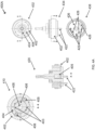
- FIG. 4A illustrates various cross-sectional and assembly views of a sequencing drive mechanism during a closed position of the disk of the valve assembly, arranged in accordance with at least some embodiments described herein.
- Diagram 400A includes cross-sectional top view 410 of the sequencing drive mechanism in the closed position with retaining housing 402, outer driver ring 404, inner driver ring 406, depressions 403 on an outside surface of the inner driver ring 406, and interlocking rollers 408.
- Diagram 400A further includes cross-sectional side view 420 of the sequencing drive mechanism with retaining housing 402, shaft 405, and guide pins 422.
- Diagram 400A also includes top view 432 of the sequencing drive mechanism with ball bearing 424, outer driver ring 404, and retaining housing 402; side view 434 of the sequencing drive mechanism with retaining housing 402 and guide pins 422; and bottom view 436 of the sequencing drive mechanism with guide pins 422, washer 426, and slotted guide holes 428 of the inner driver ring 406.
- the retaining housing 402 and the outer driver ring 404 are engaged together through the interlocking rollers 408.
- the inner driver ring 406 is free to rotate (with the shaft 405).
- the guide pins 422 may be at one extreme position within slotted guide holes 428 of the inner driver ring 406.
- FIG. 4B illustrates various cross-sectional and assembly views of a sequencing drive mechanism during a retracted position of the disk of the valve assembly, arranged in accordance with at least some embodiments described herein.
- Diagram 400B includes cross-sectional top view 410 of the sequencing drive mechanism in the retracted position with retaining housing 402, retaining housing depressions 409, outer driver ring 404, inner driver ring 406, and interlocking rollers 408.
- Diagram 400B further includes cross-sectional side view 420 of the sequencing drive mechanism with retaining housing 402, shaft 405, and guide pins 422.
- Diagram 400B also includes top view 442 of the sequencing drive mechanism with ball bearing 424, outer driver ring 404, and retaining housing 402; side view 444 of the sequencing drive mechanism with retaining housing 402 and guide pins 422; and bottom view 446 of the sequencing drive mechanism with guide pins 422, washer 426, and slotted guide holes 428 of the inner driver ring 406.
- Diagram 400B further includes a cross-sectional bottom view 450 of the valve disk 452 and link 454 with the shaft 405 in the link 454.
- the shaft 405 is rotated, for example, by about 60 degrees (401) relative to the retaining housing 402 (from the closed position of FIG. 4A ).
- the interlocking rollers 408 move from the retaining housing depressions 409 to corresponding depressions 403 on an outer surface of the inner driver ring 406.
- the inner driver ring 406 and the outer driver ring 404 are engaged together and adapted to rotate with the shaft 405 for any further turns.
- the guide pins 422 may be at another extreme position within the slotted guide holes 428 of the inner driver ring 406.
- the about 60-degree rotation of the eccentric shaft causes the link 454 to retract the valve disk 452 from a closed position with a valve gasket.
- the valve disk 452 may be disengaged from the valve gasket (retracted) by about 1.524 mm (0.060 inch).
- FIG. 4C illustrates various cross-sectional and assembly views of a sequencing drive mechanism during an open position of the disk of the valve assembly, arranged in accordance with at least some embodiments described herein.
- Diagram 400C includes cross-sectional top view 410 of the sequencing drive mechanism in the open position with retaining housing 402, retaining housing depressions 409, outer driver ring 404, inner driver ring 406, interlocking rollers 408, and shaft 405.
- Diagram 400C further includes cross-sectional side view 420 of the sequencing drive mechanism with retaining housing 402, shaft 405, and guide pins 422.
- Diagram 400C also includes top view 462 of the sequencing drive mechanism with ball bearing 424, outer driver ring 404, and retaining housing 402; side view 464 of the sequencing drive mechanism with retaining housing 402 and guide pins 422; and bottom view 466 of the sequencing drive mechanism with guide pins 422, washer 426, and slotted guide holes 428 of the inner driver ring 406.
- the shaft 405 is rotated by a total of about 150 degrees (407) relative to the retaining housing 402 (from the closed position of FIG. 4A ).
- the interlocking rollers 408 are in the depressions 403 on the outer surface of the inner driver ring 406.
- the inner driver ring 406 and the outer driver ring 404 are engaged together and rotate with the shaft 405 for the additional about 90 degrees of turn from the retracted position of FIG. 4B .
- the guide pins 422 may be at the other extreme position within the slotted guide holes 428 of the inner driver ring 406.
- the interlocking rollers 408 engaging the inner driver ring 406 and the outer driver ring 404 together for the additional about 90-degree rotation from the retracted position may cause the valve disk to rotate by about 90 degrees in the controllable flow path.
- a spherical surface of the rotated valve disk may align with the controllable flow path placing the valve assembly in the open position.
- the rotation (of the valve disk) from the retracted position may substantially reduce a friction between the valve disk surface and gasket surface, thereby a friction-caused wear and required torque to turn the valve disk may also be reduced.
- FIG. 5A illustrates an exploded assembly view and two perspective views of an eccentric shaft and attached disk of a dual motion shutoff valve assembly with a single shaft configuration, arranged in accordance with at least some embodiments described herein.
- Diagram 500A includes the exploded assembly view 510 that shows eccentric single shaft 502, top locking pin 504, top ball bearing 508, top valve link 512, valve disk 518, bottom valve link 514, bottom ball bearing 516 and bottom locking pin 506.
- First perspective view 520 of the shaft - valve disk assembly includes shaft 502, valve disk 518, bottom locking pin 506, and cammed portion 522 of the shaft 502.
- Second perspective view 530 includes same components of the shaft - valve disk assembly from a lower perspective with the top locking pin 504.
- the top and bottom valve links 512 and 514 may fit over the cammed portion 522 of the eccentric single shaft 502.
- the top and bottom valve links 512 and 514 may also be attached to the valve disk 518 via the top and bottom locking pins 504, 506.
- the top and bottom locking pins 504, 506 may be self-locking Clevis pins.
- the top and bottom ball bearings 508, 516 may provide for rotation of the shaft with less required torque.
- the ball bearings may be shielded ball bearings against environmental wear and tear (e.g., effects of the fluids or gases flowing through the valve assembly).
- FIG. 5B illustrates an exploded assembly view and two perspective views of an eccentric shaft and attached disk of a dual motion shutoff valve assembly with a dual shaft configuration, arranged in accordance with at least some embodiments described herein.
- Diagram 500B includes the exploded assembly view 540 that shows eccentric top shaft 542 and its cammed portion 548, top locking pin 504, top ball bearing 508, top valve link 512, valve disk 518, top bracket 532 of the valve disk, bottom bracket 534 of the valve disk, bottom shaft 544, and return spring 546.
- Bottom valve link 514, bottom ball bearing 516, bottom locking pin 506, may not be required and optional in some examples.
- First perspective view 550 of the shaft - valve disk assembly includes eccentric top shaft 542, cammed portion 548 of the eccentric top shaft, valve disk 518, and bottom shaft 544.
- Second perspective view 560 includes same components of the shaft - valve disk assembly from a lower perspective with self-locking extrusion 543 of the top locking pin 504.
- the top valve link 512 may fit over the cammed portion 548 of the eccentric top shaft 542.
- the top valve link 512 (with the ball bearing 508 inside) may be affixed to the top bracket 532 of the valve disk 518 through the top locking pin 504.
- the top locking pin 504 may be a self-locking (Clevis) pin with the self-locking extrusion 543.
- the cammed portion 548 of the eccentric top shaft 542 may be used to affect the retraction motion during an initial 60-degree rotation of the valve disk 518 such that the disk is disengaged from a gasket before the valve disk 518 makes its rotation within the controllable flow path of the valve assembly.
- the bottom shaft 544 may be in an oblong aperture within the bottom bracket 534 of the valve disk 518 to passively allow the retraction motion. Thus, the bottom shaft 544 may not actively cause the valve disk 518 to retract, but simply follow the motion of the eccentric top shaft 542. In other examples, a spring load within bottom shaft provided by the return spring 546 may promote linear retraction motion of valve disk 518 as the top eccentric shaft 542 begins to rotate.
- FIG. 6 illustrates cross-sectional top views of the eccentric shaft and the disk at different sections for closed, retracted, and open positions of the disk of the valve assembly, arranged in accordance with at least some embodiments described herein.
- Diagram 600 includes cross-sectional top view 602 of the assembly at a top valve link 603 when the valve disk 608 is in a closed position.
- Cross-sectional top view 602 also includes ball bearing 604, locking pin 606, locking pin aperture 605, and a partial view of the top valve bracket 609 of the valve disk 608.
- Diagram 600 also includes cross-sectional top view 616 of the assembly at the top valve link 603 when the valve disk 608 is in a retracted position and cross-sectional top view 620 of the assembly at the top valve link 603 when the valve disk 608 is in an open position.
- Diagram 600 further includes cross-sectional top views 610, 618, and 622 of the assembly at a top valve bracket 609 when the valve disk 608 is in a closed, retracted, and open position, respectively.
- the cross-sectional top views 610, 618, and 622 include a cross-section of the shaft 612 in addition to the top valve bracket 609 and the valve disk 608.
- the oblong locking pin aperture 605 may assist with side loading on the locking pin 606 during the about 60-degree rotation.
- the eccentric shaft's about 60-degree rotation may synchronize top and bottom valve links disengaging the valve disk 608 from a gasket (retraction). Following the retraction, the top valve link 603 and valve disk 608 may rotate together by about 90 degrees to the open position.
- the bottom valve link (shown in FIG. 5A ) may synchronize cam motion of the top valve link 603 for retraction and rotation.
- FIG. 7 illustrates an isometric view of a sequencing drive mechanism, shaft, disk, and gasket of a dual motion shutoff valve assembly, arranged in accordance with at least some embodiments described herein.
- Diagram 700 shows a sequencing drive assembly 702 and a single shaft 708 driven by the sequencing drive assembly 702.
- the sequencing drive assembly 702 is mechanically coupled to a top bracket 704 of the valve disk 710 through the guide pins 703.
- a further coupling is provided through the shaft 708, top valve link 706, and the top bracket 704 of the valve disk 710.
- the shaft 708 is further coupled to the valve disk 710 through the bottom valve link 712 and bottom bracket 714 of the valve disk 710.
- a gasket 720 of a valve assembly is also shown.
- the sequencing drive assembly 702 may include a mechanism comprising an inner driver ring, an outer driver ring, and interlocking rollers as shown and discussed in the figures above.
- the mechanism may cause the outer ring, and thereby the valve disk 710 to remain angularly stationary as the shaft 708 makes the initial about 60-degree turn from the closed position.
- the shaft's initial 60-degree rotation while engaged together with the inner driver ring may act on top and bottom valve links 706, 712 and cause the valve disk 710 to retract linearly from a sealing surface of the gasket 720.
- the gasket 720 may be spring energized.
- the inner driver ring may engage the outer driver ring through the interlocking rollers and allow the outer driver ring to be rotated when the shaft 708 further rotates.
- the shaft 708 may rotate both the inner and outer driver rings of the sequencing drive assembly 702, and thereby the valve disk 710 for about an additional 90 degrees before being stopped via an actuator coupled to the sequencing drive assembly 702.
- This additional about 90-degree rotation may align a spherical surface of the valve disk 710 with the controllable flow path of the valve assembly such that the valve assembly is in the open position.
- a reverse rotation of the shaft 708 may cause the valve disk 710 to rotate by about 90 degrees (with the inner driver ring and outer driver ring of the sequencing drive assembly 702 engaged together) such that a spherical surface of the valve disk 710 is aligned with the sealing surfaces of the gasket 720 (perpendicular to the controllable flow path).
- the valve disk 710 has not formed a seal with the gasket 720 yet because it is linearly disengaged (e.g., by about 1.524 mm (0.060 inch)) from the gasket 720.
- the inner driver ring may become disengaged from the outer driver ring of the sequencing drive assembly 702.
- the actuator may rotate the shaft through the sequencing drive assembly 702 for another about 60 degrees, during which the inner driver ring may rotate and the shaft and the inner driver ring may act on the top and bottom valve links 706, 712 causing the valve disk 710 to linearly move toward the gasket 720 and engage the sealing surfaces of the gasket 720 effective to place the valve assembly in the closed position again.
- Ball or butterfly valve assemblies include one or more seals formed between gaskets of inlet or outlet ports of a valve assembly and a surface of a metal ball or a butterfly disk.
- the metal ball or butterfly disk rubs against the sealing surfaces during opening and closing operations, which may result in increased friction and an increased operational torque requirement.
- the sealing surfaces (of the gaskets and/or metal ball / butterfly disk) may eventually wear out and exhibit valve internal leakage after being subjected to nominal service cycle life.
- valve assemblies disclosed herein may incorporate a sequencing drive mechanism in the valve body and utilize an eccentric shaft mechanism to linearly disengage the valve disk away from the gasket prior to rotation.
- the dual motion (retraction and rotation) may increase gasket life (thereby, valve life) by reducing friction during opening and closing operations of the valve assembly, may also reduce required operating torque for opening and closing operations, reduce pressure drop due to disk motion, and may also reduce valve leakage.
Landscapes
- Engineering & Computer Science (AREA)
- General Engineering & Computer Science (AREA)
- Mechanical Engineering (AREA)
- Lift Valve (AREA)
- Taps Or Cocks (AREA)
- Sliding Valves (AREA)
- Mechanically-Actuated Valves (AREA)
Claims (11)
- Ensemble soupape d'arrêt à double mouvement comprenant :un corps de soupape (102) comportant une paroi interne, un premier orifice (104) défini par une première partie de la paroi interne, un second orifice (104) défini par une deuxième partie de la paroi interne, et un trajet d'écoulement commandable défini par une troisième partie de la paroi interne entre le premier orifice et le second orifice ;un premier joint disposé autour du premier orifice ;un disque de soupape (110) disposé dans le trajet d'écoulement commandable, ledit disque de soupape comprenant une partie de surface sphérique conçue pour se mettre en prise sélectivement avec le premier joint dans une position fermée de l'ensemble soupape efficace pour former un joint d'étanchéité sur celui-ci ;un arbre (112) couplé au disque de soupape, l'arbre étant conçu pour actionner une position du disque de soupape entre la position fermée et une position ouverte de sorte que le disque de soupape soit placé dans une position rétractée par rapport au premier joint lorsque l'arbre est déplacé de la position fermée à la position ouverte ou de la position ouverte à la position fermée ; etun ensemble d'entraînement de séquençage (106) couplé à l'arbre et au disque de soupape, ledit ensemble d'entraînement de séquençage étant conçu pour actionner une position de l'arbre entre la position ouverte et la position fermée,caractérisé en ce que l'ensemble d'entraînement de séquençage comprend :une bague d'entraînement interne (306) conçue pour entourer l'arbre, la bague d'entraînement interne comportant une paroi latérale et deux dépressions au niveau d'emplacements opposés sur une surface extérieure de la paroi latérale de la bague d'entraînement interne ;une bague d'entraînement externe (304) conçue pour entourer la bague d'entraînement interne, la bague d'entraînement externe comportant une paroi latérale et deux ouvertures autour d'emplacements opposés de la paroi latérale de la bague d'entraînement externe ;un boîtier de retenue (302) conçu pour entourer la bague d'entraînement interne et la bague d'entraînement externe, le boîtier de retenue comportant une paroi latérale et deux dépressions autour d'emplacements opposés d'une surface intérieure de la paroi latérale du boîtier de retenue ; etune paire de rouleaux d'interverrouillage (308) conçus pour se mettre en prise de manière coulissante dans les deux ouvertures autour des emplacements opposés de la paroi latérale de la bague d'entraînement externe.
- Ensemble soupape de la revendication 1, ledit ensemble d'entraînement de séquençage étant conçu pour :amener le disque de soupape à se séparer du premier joint et à se rétracter linéairement du premier joint durant une rotation de l'arbre de la position fermée à la position rétractée ;ensuite amener le disque de soupape à se déplacer en rotation de la position rétractée à la position ouverte ;amener le disque de soupape à se déplacer en rotation de la position ouverte à la position rétractée ; etensuite amener le disque de soupape à s'étendre linéairement vers le premier joint et à se mettre en prise avec le premier joint durant une autre rotation de l'arbre de la position rétractée à la position fermée.
- Ensemble soupape de la revendication 1, ledit ensemble d'entraînement de séquençage étant conçu pour :à partir de la position fermée, actionner une rotation d'environ 60 degrés de l'arbre durant laquelle le disque de soupape passe de la position fermée à la position rétractée ; etactionner une rotation supplémentaire d'environ 90 degrés de l'arbre durant laquelle le disque de soupape passe de la position rétractée à la position ouverte ; età partir de la position ouverte, actionner une rotation d'environ 90 degrés de l'arbre durant laquelle le disque de soupape passe de la position ouverte à la position rétractée ; etactionner une rotation supplémentaire d'environ 60 degrés de l'arbre durant laquelle le disque de soupape passe de la position rétractée à la position fermée.
- Ensemble soupape de la revendication 1, ladite paire de rouleaux d'interverrouillage étant conçus pour :mettre en prise la bague d'entraînement externe et le boîtier de retenue ensemble par coulissement dans les deux dépressions au niveau d'emplacements opposés de la surface intérieure de la paroi latérale du boîtier de retenue durant une rotation de l'arbre de la position fermée à la position rétractée ou de la position rétractée à la position fermée de l'ensemble soupape efficace pour amener le disque de soupape à rester angulairement immobile durant la rotation de l'arbre ; etmettre en prise la bague d'entraînement interne et la bague d'entraînement externe par coulissement dans les deux dépressions au niveau d' emplacements opposés de la surface extérieure de la paroi latérale de la bague d'entraînement internedurant une autre rotation de l'arbre de la position rétractée à la position ouverte ou de la position ouverte à la position rétractée de l'ensemble de soupape efficace pour amener le disque de soupape à tourner durant l'autre rotation de l'arbre.
- Ensemble soupape de la revendication 4,ledit ensemble d'entraînement de séquençage comprenant en outre trois broches de guidage qui s'étendent à partir d'une surface inférieure de la bague d'entraînement externe, les trois broches de guidage étant conçues pour se mettre en prise dans trois ouvertures correspondantes dans un support supérieur couplé au disque de soupape, etlesdites trois ouvertures correspondantes dans le support supérieur étant formées pour permettre aux trois broches de guidage dese déplacer librement durant une rotation de l'arbre de la position fermée à la position rétractée ou de la position rétractée à la position fermée de l'ensemble soupape efficace pour amener le disque de soupape à rester angulairement immobile durant la rotation de l'arbre, ouamener le support supérieur à se déplacer durant une rotation de l'arbre de la position rétractée à la position ouverte ou de la position ouverte à la position rétractée de l'ensemble soupape efficace pour amener le disque de soupape à tourner durant la rotation de l'arbre.
- Ensemble soupape de la revendication 1, ledit disque de soupape comprenant :un support supérieur qui s'étend à partir d'une partie supérieure de la partie de surface sphérique du disque de soupape et comprend une première ouverture pour le passage de l'arbre, une partie supérieure à came de l'arbre étant conçue pour se mettre en prise de manière coulissante dans la première ouverture du support supérieur ; etun support inférieur qui s'étend à partir d'une partie inférieure de la partie de surface sphérique du disque de soupape et comprend une seconde ouverture pour le passage de l'arbre, une partie inférieure à came de l'arbre étant conçue pour se mettre en prise de manière coulissante dans la seconde ouverture du support inférieur.
- Ensemble soupape de la revendication 6, comprenant en outre :une liaison de soupape supérieure couplée de manière mobile au support supérieur ;un arbre inférieur couplé de manière mobile au support inférieur ; etune liaison de soupape inférieure couplée de manière mobile au support inférieur,ladite liaison de soupape supérieure comprenant un roulement à billes pour maintenir l'arbre et une troisième ouverture adaptée pour recevoir une broche de verrouillage qui est insérée à travers le support supérieur pour fixer la liaison de soupape supérieure au support supérieur ; etladite liaison de soupape inférieure comprenant un autre roulement à billes pour maintenir l'arbre et une quatrième ouverture adaptée pour recevoir une autre broche de verrouillage qui est insérée à travers le support inférieur pour fixer la liaison de soupape inférieure au support inférieur.
- Procédé pour fabriquer un ensemble soupape d'arrêt à double mouvement, le procédé comprenant :la formation d'un corps de soupape (102) comportant une paroi interne, une première partie de la paroi interne, une deuxième partie de la paroi interne et une troisième partie de la paroi interne, de sorte quela première partie de la paroi interne définisse un premier orifice (104) du corps de soupape,la deuxième partie de la paroi interne définisse un second orifice (104) du corps de soupape, etla troisième partie de la paroi interne, le premier orifice et le second orifice définissent un trajet d'écoulement commandable qui s'étend le long de la paroi interne entre le premier orifice et le second orifice du corps de soupape ;la disposition d'un premier joint autour du premier orifice du corps de soupape ;la formation d'un disque de soupape (110) pour comprendre au moins une partie de surface sphérique ;la disposition du disque de soupape dans le trajet d'écoulement commandable du corps de soupape de sorte que la partie de surface sphérique se mette en prise sélectivement avec le premier joint dans une position fermée de l'ensemble soupape efficace pour former un joint d'étanchéité sur celui-ci ;la formation d'un arbre (112) pour actionner une position du disque de soupape entre la position fermée et une position ouverte ;le couplage de l'arbre au disque de soupape de manière décalée de sorte que le disque de soupape soit placé dans une position rétractée par rapport au premier joint lorsque l'arbre est déplacé de la position fermée à la position ouverte ou de la position ouverte à la position fermée ;la formation d'un ensemble d'entraînement de séquençage (106) ; etle couplage de l'ensemble d'entraînement de séquençage à l'arbre et au disque de soupape pour actionner une position de l'arbre entre la position ouverte et la position fermée ;caractérisé en ce quela formation de l'ensemble d'entraînement de séquençage comprend :la formation d'une bague d'entraînement interne (306) pour entourer l'arbre, la bague d'entraînement interne comportant une paroi latérale et deux dépressions au niveau d'emplacements opposés sur une surface extérieure de la paroi latérale de la bague d'entraînement interne ;la formation d'une bague d'entraînement externe (304) pour entourer la bague d'entraînement interne, la bague d'entraînement externe comportant une paroi latérale et deux ouvertures autour d'emplacements opposés de la paroi latérale de la bague d'entraînement externe ;la formation d'un boîtier de retenue (302) pour entourer la bague d'entraînement interne et la bague d'entraînement externe, le boîtier de retenue comportant une paroi latérale et deux dépressions autour d'emplacements opposés d'une surface intérieure de la paroi latérale du boîtier de retenue ; etla formation d'une paire de rouleaux d'interverrouillage (308) pour se mettre en prise de manière coulissante dans les deux ouvertures autour des emplacements opposés de la paroi latérale de la bague d'entraînement externe.
- Procédé de la revendication 8, ladite formation de l'ensemble d'entraînement de séquençage comprenant : la formation de l'ensemble d'entraînement de séquençage pouramener le disque de soupape à se séparer du premier joint et à se rétracter linéairement du premier joint durant une rotation de l'arbre de la position fermée à la position rétractée, et ensuite à amener le disque de soupape à se déplacer en rotation de la position rétractée à la position ouverte ; etamener le disque de soupape à se déplacer en rotation de la position ouverte à la position rétractée, et ensuite amener le disque de soupape à s'étendre linéairement vers le premier joint et à se mettre en prise avec le premier joint durant une autre rotation de l'arbre de la position rétractée à la position fermée.
- Procédé de la revendication 8,
ladite formation de la bague d'entraînement externe, du boîtier de retenue et de la paire de rouleaux d'interverrouillage comprenant :l'agencement de la paire de rouleaux d'interverrouillage pour mettre en prise la bague d'entraînement externe et le boîtier de retenue ensemble par coulissement dans les deux dépressions au niveau d'emplacements opposés de la surface intérieure de la paroi latérale du boîtier de retenue durant une rotation de l'arbre de la position fermée à la position rétractée ou de la position rétractée à la position fermée de l'ensemble soupape efficace pour amener le disque de soupape à rester angulairement immobile durant la rotation de l'arbre ; etladite formation de la bague d'entraînement interne, de la bague d'entraînement externe et de la paire de rouleaux d'interverrouillage comprenant :l'agencement de la paire de rouleaux d'interverrouillage pour mettre en prise la bague d'entraînement interne et la bague d'entraînement externe par coulissement dans les deux dépressions au niveau d'emplacements opposés de la surface extérieure de la paroi latérale de la bague d'entraînement interne durant une rotation del'arbre de la position rétractée à la position ouverte ou de la position ouverte à la position rétractée de l'ensemble de soupape efficace pour amener le disque de soupape à tourner durant la rotation de l'arbre. - Procédé de la revendication 8, ladite formation de l'arbre pour actionner la position du disque de soupape entre la position fermée et la position ouverte comprenant :la formation d'un arbre supérieur pour actionner la position du disque de soupape entre la position fermée et la position ouverte ;le couplage de l'arbre supérieur à une partie supérieure du disque de soupape de manière décalée de sorte que le disque de soupape soit placé dans une position rétractée par rapport au premier joint lorsque l'arbre supérieur est déplacé de la position fermée à la position ouverte ou de la position ouverte à la position fermée ;la formation d'un arbre inférieur couplé à une partie inférieure du disque de soupape ; etle couplage de l'arbre inférieur à la partie inférieure du disque de soupape.
Applications Claiming Priority (1)
| Application Number | Priority Date | Filing Date | Title |
|---|---|---|---|
| PCT/US2019/062528 WO2021101544A1 (fr) | 2019-11-21 | 2019-11-21 | Soupape d'arrêt à double mouvement |
Publications (3)
| Publication Number | Publication Date |
|---|---|
| EP4062087A1 EP4062087A1 (fr) | 2022-09-28 |
| EP4062087A4 EP4062087A4 (fr) | 2023-08-16 |
| EP4062087B1 true EP4062087B1 (fr) | 2025-06-04 |
Family
ID=75981696
Family Applications (1)
| Application Number | Title | Priority Date | Filing Date |
|---|---|---|---|
| EP19953061.9A Active EP4062087B1 (fr) | 2019-11-21 | 2019-11-21 | Soupape d'arrêt à double mouvement |
Country Status (7)
| Country | Link |
|---|---|
| US (1) | US11796066B2 (fr) |
| EP (1) | EP4062087B1 (fr) |
| JP (1) | JP7379701B2 (fr) |
| KR (3) | KR20240058946A (fr) |
| CN (1) | CN114729700B (fr) |
| CA (1) | CA3159547A1 (fr) |
| WO (1) | WO2021101544A1 (fr) |
Families Citing this family (1)
| Publication number | Priority date | Publication date | Assignee | Title |
|---|---|---|---|---|
| US20250369518A1 (en) * | 2022-05-24 | 2025-12-04 | Pierburg Gmbh | Flap device for an internal combustion engine |
Family Cites Families (26)
| Publication number | Priority date | Publication date | Assignee | Title |
|---|---|---|---|---|
| US3498583A (en) * | 1966-10-07 | 1970-03-03 | Martin Marietta Corp | Compound movement butterfly valve |
| GB1282365A (en) * | 1970-07-06 | 1972-07-19 | Fwi Inc | Butterfly valve having improved positive closure means |
| US3697042A (en) * | 1971-01-21 | 1972-10-10 | Walworth Co | Dual action butterfly valve |
| JPS5036689B2 (fr) * | 1971-09-30 | 1975-11-27 | ||
| JPS49143831U (fr) * | 1974-01-11 | 1974-12-11 | ||
| US4288060A (en) | 1979-12-21 | 1981-09-08 | The United States Of America As Represented By The United States Department Of Energy | Sequenced drive for rotary valves |
| CA1228584A (fr) * | 1984-03-15 | 1987-10-27 | 596801 Ontario Limited | Robinet a boisseau spherique |
| JPS6138359U (ja) * | 1984-08-10 | 1986-03-10 | 大阪機器製造株式会社 | 弁の開閉駆動機構 |
| US4763877A (en) | 1987-09-29 | 1988-08-16 | Itt Corporation | Butterfly valve seal arrangement |
| LU87482A1 (fr) * | 1989-03-17 | 1990-10-02 | Wurth Paul Sa | Dispositif d'obturation de conduites de transport de produits en vrac |
| DE4201826A1 (de) | 1992-01-24 | 1993-07-29 | Teves Gmbh Alfred | Pumpe mit einem druckventil |
| US5567118A (en) | 1995-02-14 | 1996-10-22 | Itt Fluid Technology Corporation | Non-lubricated, air-actuated, pump-operating, shuttle valve arrangement, in a reciprocating pump |
| US5755427A (en) * | 1996-02-23 | 1998-05-26 | Naf Ab | Self adjusting ball valve assembly |
| US5666991A (en) | 1995-12-05 | 1997-09-16 | Itt Automotive Inc. | Shut-off valve for evacuation and fill without energizing valve |
| JP3242869B2 (ja) | 1996-12-26 | 2001-12-25 | 岡野バルブ製造株式会社 | 弁装置 |
| US6135416A (en) * | 1999-02-18 | 2000-10-24 | Varian, Inc. | Butterfly valve |
| US7080820B2 (en) * | 1999-11-16 | 2006-07-25 | Fisher Controls International Llc. | Elliptical sealing surface for butterfly valve |
| AUPR158100A0 (en) * | 2000-11-20 | 2000-12-14 | Chapman, John Edward | Valve system |
| US20090274566A1 (en) | 2008-04-30 | 2009-11-05 | Itt Manufacturing Enterprises, Inc. | Check valve with plastic lip seal |
| US20100200791A1 (en) * | 2009-02-07 | 2010-08-12 | Victaulic Company | Valve Having High Pressure and Low Pressure Seals |
| JP5490435B2 (ja) * | 2009-03-31 | 2014-05-14 | 東京エレクトロン株式会社 | ゲートバルブ装置 |
| US20110162730A1 (en) | 2010-01-04 | 2011-07-07 | Itt Manufacturing Enterprises, Inc. | Valve for a pressure regulator |
| CN103026109B (zh) * | 2010-05-14 | 2014-09-10 | 布雷国际有限公司 | 阀组件和阀组件的使用方法 |
| JP5490642B2 (ja) * | 2010-07-28 | 2014-05-14 | 株式会社パウレック | 円板状部材の反転機構 |
| JP6370705B2 (ja) * | 2014-12-26 | 2018-08-08 | 日立Geニュークリア・エナジー株式会社 | バタフライ弁 |
| JP3201573U (ja) * | 2015-10-05 | 2015-12-17 | イハラサイエンス株式会社 | バルブ |
-
2019
- 2019-11-21 EP EP19953061.9A patent/EP4062087B1/fr active Active
- 2019-11-21 KR KR1020247012882A patent/KR20240058946A/ko not_active Ceased
- 2019-11-21 WO PCT/US2019/062528 patent/WO2021101544A1/fr not_active Ceased
- 2019-11-21 US US17/777,061 patent/US11796066B2/en active Active
- 2019-11-21 CN CN201980102368.XA patent/CN114729700B/zh active Active
- 2019-11-21 CA CA3159547A patent/CA3159547A1/fr active Pending
- 2019-11-21 KR KR1020227016579A patent/KR102715391B1/ko active Active
- 2019-11-21 JP JP2022529352A patent/JP7379701B2/ja active Active
- 2019-11-21 KR KR1020247005103A patent/KR102747270B1/ko active Active
Also Published As
| Publication number | Publication date |
|---|---|
| KR20240058946A (ko) | 2024-05-07 |
| EP4062087A4 (fr) | 2023-08-16 |
| CA3159547A1 (fr) | 2021-05-27 |
| WO2021101544A1 (fr) | 2021-05-27 |
| US11796066B2 (en) | 2023-10-24 |
| KR20220101636A (ko) | 2022-07-19 |
| EP4062087A1 (fr) | 2022-09-28 |
| KR102747270B1 (ko) | 2024-12-26 |
| CN114729700A (zh) | 2022-07-08 |
| KR20240024368A (ko) | 2024-02-23 |
| JP2023503888A (ja) | 2023-02-01 |
| JP7379701B2 (ja) | 2023-11-14 |
| CN114729700B (zh) | 2024-03-01 |
| KR102715391B1 (ko) | 2024-10-11 |
| US20220397199A1 (en) | 2022-12-15 |
Similar Documents
| Publication | Publication Date | Title |
|---|---|---|
| CA2698630C (fr) | Joint de soupape a bille haute temperature | |
| EP2299152B1 (fr) | Soupape à bille dotée d'un plateau de pression anti-rotation | |
| US6158718A (en) | Gate valve | |
| US8070130B2 (en) | Apparatus to bias valve closure members | |
| US4029292A (en) | Globe valve construction | |
| JP7467359B2 (ja) | ボール弁及び弁動作方法 | |
| EP4062087B1 (fr) | Soupape d'arrêt à double mouvement | |
| HU225807B1 (en) | Double acting ball valve | |
| US20180163879A1 (en) | Subsea Valve With Non-Circular Sliding Metal Seals | |
| CN110425297A (zh) | 一种高可调比旋塞调节阀 | |
| US5899438A (en) | Gate valve having a swingable-slidable valve plate | |
| US4482128A (en) | High pressure cam seal valve | |
| KR200407191Y1 (ko) | 안전장치가 구비된 버터플라이밸브 | |
| JP2019094991A (ja) | 流量制御装置 | |
| RU2301367C2 (ru) | Задвижка | |
| RU164880U1 (ru) | Запорно-регулирующая задвижка | |
| KR200355269Y1 (ko) | 이중 안전위치핀 내장 솔리이드 메탈 시트 버터플라이밸브 | |
| NO20260093A1 (en) | Subsea valve with non-circular sliding metal seals | |
| CA2137171A1 (fr) | Robinet d'isolement a membrane a volume variable | |
| GB2166846A (en) | Improved high pressure cam seal valve | |
| JPS61116175A (ja) | 高圧カムシ−ル弁 |
Legal Events
| Date | Code | Title | Description |
|---|---|---|---|
| STAA | Information on the status of an ep patent application or granted ep patent |
Free format text: STATUS: THE INTERNATIONAL PUBLICATION HAS BEEN MADE |
|
| PUAI | Public reference made under article 153(3) epc to a published international application that has entered the european phase |
Free format text: ORIGINAL CODE: 0009012 |
|
| STAA | Information on the status of an ep patent application or granted ep patent |
Free format text: STATUS: REQUEST FOR EXAMINATION WAS MADE |
|
| 17P | Request for examination filed |
Effective date: 20220519 |
|
| AK | Designated contracting states |
Kind code of ref document: A1 Designated state(s): AL AT BE BG CH CY CZ DE DK EE ES FI FR GB GR HR HU IE IS IT LI LT LU LV MC MK MT NL NO PL PT RO RS SE SI SK SM TR |
|
| DAV | Request for validation of the european patent (deleted) | ||
| DAX | Request for extension of the european patent (deleted) | ||
| A4 | Supplementary search report drawn up and despatched |
Effective date: 20230717 |
|
| RIC1 | Information provided on ipc code assigned before grant |
Ipc: F16K 31/524 20060101ALI20230711BHEP Ipc: F16K 1/28 20060101ALI20230711BHEP Ipc: F16K 1/26 20060101ALI20230711BHEP Ipc: F16K 1/22 20060101ALI20230711BHEP Ipc: F16K 1/20 20060101ALI20230711BHEP Ipc: F16K 1/18 20060101ALI20230711BHEP Ipc: F16K 1/24 20060101AFI20230711BHEP |
|
| P01 | Opt-out of the competence of the unified patent court (upc) registered |
Free format text: CASE NUMBER: APP_48991/2024 Effective date: 20240828 |
|
| GRAP | Despatch of communication of intention to grant a patent |
Free format text: ORIGINAL CODE: EPIDOSNIGR1 |
|
| STAA | Information on the status of an ep patent application or granted ep patent |
Free format text: STATUS: GRANT OF PATENT IS INTENDED |
|
| INTG | Intention to grant announced |
Effective date: 20250116 |
|
| GRAS | Grant fee paid |
Free format text: ORIGINAL CODE: EPIDOSNIGR3 |
|
| GRAA | (expected) grant |
Free format text: ORIGINAL CODE: 0009210 |
|
| STAA | Information on the status of an ep patent application or granted ep patent |
Free format text: STATUS: THE PATENT HAS BEEN GRANTED |
|
| AK | Designated contracting states |
Kind code of ref document: B1 Designated state(s): AL AT BE BG CH CY CZ DE DK EE ES FI FR GB GR HR HU IE IS IT LI LT LU LV MC MK MT NL NO PL PT RO RS SE SI SK SM TR |
|
| REG | Reference to a national code |
Ref country code: GB Ref legal event code: FG4D |
|
| REG | Reference to a national code |
Ref country code: CH Ref legal event code: EP |
|
| REG | Reference to a national code |
Ref country code: DE Ref legal event code: R096 Ref document number: 602019070944 Country of ref document: DE |
|
| REG | Reference to a national code |
Ref country code: IE Ref legal event code: FG4D |
|
| REG | Reference to a national code |
Ref country code: NL Ref legal event code: MP Effective date: 20250604 |
|
| PG25 | Lapsed in a contracting state [announced via postgrant information from national office to epo] |
Ref country code: FI Free format text: LAPSE BECAUSE OF FAILURE TO SUBMIT A TRANSLATION OF THE DESCRIPTION OR TO PAY THE FEE WITHIN THE PRESCRIBED TIME-LIMIT Effective date: 20250604 Ref country code: ES Free format text: LAPSE BECAUSE OF FAILURE TO SUBMIT A TRANSLATION OF THE DESCRIPTION OR TO PAY THE FEE WITHIN THE PRESCRIBED TIME-LIMIT Effective date: 20250604 |
|
| REG | Reference to a national code |
Ref country code: LT Ref legal event code: MG9D |
|
| PG25 | Lapsed in a contracting state [announced via postgrant information from national office to epo] |
Ref country code: NO Free format text: LAPSE BECAUSE OF FAILURE TO SUBMIT A TRANSLATION OF THE DESCRIPTION OR TO PAY THE FEE WITHIN THE PRESCRIBED TIME-LIMIT Effective date: 20250904 Ref country code: GR Free format text: LAPSE BECAUSE OF FAILURE TO SUBMIT A TRANSLATION OF THE DESCRIPTION OR TO PAY THE FEE WITHIN THE PRESCRIBED TIME-LIMIT Effective date: 20250905 |
|
| PG25 | Lapsed in a contracting state [announced via postgrant information from national office to epo] |
Ref country code: PL Free format text: LAPSE BECAUSE OF FAILURE TO SUBMIT A TRANSLATION OF THE DESCRIPTION OR TO PAY THE FEE WITHIN THE PRESCRIBED TIME-LIMIT Effective date: 20250604 |
|
| PG25 | Lapsed in a contracting state [announced via postgrant information from national office to epo] |
Ref country code: BG Free format text: LAPSE BECAUSE OF FAILURE TO SUBMIT A TRANSLATION OF THE DESCRIPTION OR TO PAY THE FEE WITHIN THE PRESCRIBED TIME-LIMIT Effective date: 20250604 |
|
| PG25 | Lapsed in a contracting state [announced via postgrant information from national office to epo] |
Ref country code: HR Free format text: LAPSE BECAUSE OF FAILURE TO SUBMIT A TRANSLATION OF THE DESCRIPTION OR TO PAY THE FEE WITHIN THE PRESCRIBED TIME-LIMIT Effective date: 20250604 |
|
| PG25 | Lapsed in a contracting state [announced via postgrant information from national office to epo] |
Ref country code: RS Free format text: LAPSE BECAUSE OF FAILURE TO SUBMIT A TRANSLATION OF THE DESCRIPTION OR TO PAY THE FEE WITHIN THE PRESCRIBED TIME-LIMIT Effective date: 20250904 |
|
| PG25 | Lapsed in a contracting state [announced via postgrant information from national office to epo] |
Ref country code: LV Free format text: LAPSE BECAUSE OF FAILURE TO SUBMIT A TRANSLATION OF THE DESCRIPTION OR TO PAY THE FEE WITHIN THE PRESCRIBED TIME-LIMIT Effective date: 20250604 |
|
| PG25 | Lapsed in a contracting state [announced via postgrant information from national office to epo] |
Ref country code: NL Free format text: LAPSE BECAUSE OF FAILURE TO SUBMIT A TRANSLATION OF THE DESCRIPTION OR TO PAY THE FEE WITHIN THE PRESCRIBED TIME-LIMIT Effective date: 20250604 |
|
| PG25 | Lapsed in a contracting state [announced via postgrant information from national office to epo] |
Ref country code: PT Free format text: LAPSE BECAUSE OF FAILURE TO SUBMIT A TRANSLATION OF THE DESCRIPTION OR TO PAY THE FEE WITHIN THE PRESCRIBED TIME-LIMIT Effective date: 20251006 |
|
| REG | Reference to a national code |
Ref country code: AT Ref legal event code: MK05 Ref document number: 1800600 Country of ref document: AT Kind code of ref document: T Effective date: 20250604 |
|
| PG25 | Lapsed in a contracting state [announced via postgrant information from national office to epo] |
Ref country code: IS Free format text: LAPSE BECAUSE OF FAILURE TO SUBMIT A TRANSLATION OF THE DESCRIPTION OR TO PAY THE FEE WITHIN THE PRESCRIBED TIME-LIMIT Effective date: 20251004 |
|
| PGFP | Annual fee paid to national office [announced via postgrant information from national office to epo] |
Ref country code: GB Payment date: 20251023 Year of fee payment: 7 |
|
| PG25 | Lapsed in a contracting state [announced via postgrant information from national office to epo] |
Ref country code: SM Free format text: LAPSE BECAUSE OF FAILURE TO SUBMIT A TRANSLATION OF THE DESCRIPTION OR TO PAY THE FEE WITHIN THE PRESCRIBED TIME-LIMIT Effective date: 20250604 Ref country code: AT Free format text: LAPSE BECAUSE OF FAILURE TO SUBMIT A TRANSLATION OF THE DESCRIPTION OR TO PAY THE FEE WITHIN THE PRESCRIBED TIME-LIMIT Effective date: 20250604 |
|
| PGFP | Annual fee paid to national office [announced via postgrant information from national office to epo] |
Ref country code: FR Payment date: 20251022 Year of fee payment: 7 |
|
| PG25 | Lapsed in a contracting state [announced via postgrant information from national office to epo] |
Ref country code: CZ Free format text: LAPSE BECAUSE OF FAILURE TO SUBMIT A TRANSLATION OF THE DESCRIPTION OR TO PAY THE FEE WITHIN THE PRESCRIBED TIME-LIMIT Effective date: 20250604 |
|
| PG25 | Lapsed in a contracting state [announced via postgrant information from national office to epo] |
Ref country code: EE Free format text: LAPSE BECAUSE OF FAILURE TO SUBMIT A TRANSLATION OF THE DESCRIPTION OR TO PAY THE FEE WITHIN THE PRESCRIBED TIME-LIMIT Effective date: 20250604 |
|
| PG25 | Lapsed in a contracting state [announced via postgrant information from national office to epo] |
Ref country code: SK Free format text: LAPSE BECAUSE OF FAILURE TO SUBMIT A TRANSLATION OF THE DESCRIPTION OR TO PAY THE FEE WITHIN THE PRESCRIBED TIME-LIMIT Effective date: 20250604 |
|
| PG25 | Lapsed in a contracting state [announced via postgrant information from national office to epo] |
Ref country code: IT Free format text: LAPSE BECAUSE OF FAILURE TO SUBMIT A TRANSLATION OF THE DESCRIPTION OR TO PAY THE FEE WITHIN THE PRESCRIBED TIME-LIMIT Effective date: 20250604 |
|
| PG25 | Lapsed in a contracting state [announced via postgrant information from national office to epo] |
Ref country code: RO Free format text: LAPSE BECAUSE OF FAILURE TO SUBMIT A TRANSLATION OF THE DESCRIPTION OR TO PAY THE FEE WITHIN THE PRESCRIBED TIME-LIMIT Effective date: 20250604 |
|
| REG | Reference to a national code |
Ref country code: DE Ref legal event code: R097 Ref document number: 602019070944 Country of ref document: DE |
|
| PLBE | No opposition filed within time limit |
Free format text: ORIGINAL CODE: 0009261 |
|
| STAA | Information on the status of an ep patent application or granted ep patent |
Free format text: STATUS: NO OPPOSITION FILED WITHIN TIME LIMIT |
|
| PG25 | Lapsed in a contracting state [announced via postgrant information from national office to epo] |
Ref country code: DK Free format text: LAPSE BECAUSE OF FAILURE TO SUBMIT A TRANSLATION OF THE DESCRIPTION OR TO PAY THE FEE WITHIN THE PRESCRIBED TIME-LIMIT Effective date: 20250604 |
|
| REG | Reference to a national code |
Ref country code: CH Ref legal event code: L10 Free format text: ST27 STATUS EVENT CODE: U-0-0-L10-L00 (AS PROVIDED BY THE NATIONAL OFFICE) Effective date: 20260416 |