EP4062749B1 - Dispositif et procédé de culture pour plantes - Google Patents
Dispositif et procédé de culture pour plantes Download PDFInfo
- Publication number
- EP4062749B1 EP4062749B1 EP22162387.9A EP22162387A EP4062749B1 EP 4062749 B1 EP4062749 B1 EP 4062749B1 EP 22162387 A EP22162387 A EP 22162387A EP 4062749 B1 EP4062749 B1 EP 4062749B1
- Authority
- EP
- European Patent Office
- Prior art keywords
- planting
- plants
- container
- folds
- planting surface
- Prior art date
- Legal status (The legal status is an assumption and is not a legal conclusion. Google has not performed a legal analysis and makes no representation as to the accuracy of the status listed.)
- Active
Links
Images






Classifications
-
- A—HUMAN NECESSITIES
- A01—AGRICULTURE; FORESTRY; ANIMAL HUSBANDRY; HUNTING; TRAPPING; FISHING
- A01G—HORTICULTURE; CULTIVATION OF VEGETABLES, FLOWERS, RICE, FRUIT, VINES, HOPS OR SEAWEED; FORESTRY; WATERING
- A01G9/00—Cultivation in receptacles, forcing-frames or greenhouses; Edging for beds, lawn or the like
- A01G9/02—Receptacles, e.g. flower-pots or boxes; Glasses for cultivating flowers
- A01G9/029—Receptacles for seedlings
-
- A—HUMAN NECESSITIES
- A01—AGRICULTURE; FORESTRY; ANIMAL HUSBANDRY; HUNTING; TRAPPING; FISHING
- A01G—HORTICULTURE; CULTIVATION OF VEGETABLES, FLOWERS, RICE, FRUIT, VINES, HOPS OR SEAWEED; FORESTRY; WATERING
- A01G31/00—Soilless cultivation, e.g. hydroponics
- A01G31/02—Special apparatus therefor
- A01G31/06—Hydroponic culture on racks or in stacked containers
-
- A—HUMAN NECESSITIES
- A01—AGRICULTURE; FORESTRY; ANIMAL HUSBANDRY; HUNTING; TRAPPING; FISHING
- A01G—HORTICULTURE; CULTIVATION OF VEGETABLES, FLOWERS, RICE, FRUIT, VINES, HOPS OR SEAWEED; FORESTRY; WATERING
- A01G9/00—Cultivation in receptacles, forcing-frames or greenhouses; Edging for beds, lawn or the like
- A01G9/02—Receptacles, e.g. flower-pots or boxes; Glasses for cultivating flowers
- A01G9/026—Foldable pots
-
- A—HUMAN NECESSITIES
- A01—AGRICULTURE; FORESTRY; ANIMAL HUSBANDRY; HUNTING; TRAPPING; FISHING
- A01G—HORTICULTURE; CULTIVATION OF VEGETABLES, FLOWERS, RICE, FRUIT, VINES, HOPS OR SEAWEED; FORESTRY; WATERING
- A01G9/00—Cultivation in receptacles, forcing-frames or greenhouses; Edging for beds, lawn or the like
- A01G9/02—Receptacles, e.g. flower-pots or boxes; Glasses for cultivating flowers
- A01G9/028—Multi-compartmented pots
-
- A—HUMAN NECESSITIES
- A01—AGRICULTURE; FORESTRY; ANIMAL HUSBANDRY; HUNTING; TRAPPING; FISHING
- A01G—HORTICULTURE; CULTIVATION OF VEGETABLES, FLOWERS, RICE, FRUIT, VINES, HOPS OR SEAWEED; FORESTRY; WATERING
- A01G9/00—Cultivation in receptacles, forcing-frames or greenhouses; Edging for beds, lawn or the like
- A01G9/02—Receptacles, e.g. flower-pots or boxes; Glasses for cultivating flowers
- A01G9/029—Receptacles for seedlings
- A01G9/0295—Units comprising two or more connected receptacles
-
- Y—GENERAL TAGGING OF NEW TECHNOLOGICAL DEVELOPMENTS; GENERAL TAGGING OF CROSS-SECTIONAL TECHNOLOGIES SPANNING OVER SEVERAL SECTIONS OF THE IPC; TECHNICAL SUBJECTS COVERED BY FORMER USPC CROSS-REFERENCE ART COLLECTIONS [XRACs] AND DIGESTS
- Y02—TECHNOLOGIES OR APPLICATIONS FOR MITIGATION OR ADAPTATION AGAINST CLIMATE CHANGE
- Y02P—CLIMATE CHANGE MITIGATION TECHNOLOGIES IN THE PRODUCTION OR PROCESSING OF GOODS
- Y02P60/00—Technologies relating to agriculture, livestock or agroalimentary industries
- Y02P60/20—Reduction of greenhouse gas [GHG] emissions in agriculture, e.g. CO2
- Y02P60/21—Dinitrogen oxide [N2O], e.g. using aquaponics, hydroponics or efficiency measures
Definitions
- the invention relates to a device for growing plants according to the preamble of claim 1 and to methods for growing plants according to the preamble of claims 13, 14 and 15.
- Such a device for growing plants can be used, for example, in vertical farming.
- the term vertical farming refers to the cultivation of plants in closed rooms, on several floors above one another, under natural or artificial light.
- the plants are crops, such as fruit and vegetables, which are grown and harvested all year round. This is achieved in particular through artificial lighting, climate control and a controlled supply of nutrients.
- Hydroponics is a method of cultivation in which the plants do not have their roots in the soil, but in containers in which they are fixed with a substrate (e.g. coconut fiber or rock wool, etc.). Hydroponics is a form of hydroponics and is used for the systematic cultivation of crops and ornamental plants.
- a hydroponic system the roots of the plant hang in a mixture of water and dissolved nutrients.
- the plant is usually supported by a planting surface, such as a substrate or a growth medium in the Plant containers are fixed.
- the plants are supplied with water and nutrients via a computer-controlled circulation system.
- aeroponics refers to a hydroponic cultivation method in which plants are cultivated without a growth medium such as soil. The roots of the plant hang freely in the air below a planting area and are sprayed with a water-nutrient solution at regular intervals. This increases the oxygen content in the root system, which in turn has a positive effect on plant growth.
- the cuttings or young plants require little space in the plant containers in the early stages. This means that many small plants can be planted in one plant container. As the plants grow, however, the plant container becomes too small and the plants shade each other. By separating the plants, the plants are better exposed to light. Good lighting during the growth of the plants therefore plays an important role, because with good lighting, the vegetable and plant yield can be maximized and the plants stay healthier. Due to the high energy requirements of artificial lighting, a denser cultivation method also uses less energy per plant. It is important that each photon of artificial light hits a green area (leaves, etc.) of the plant if possible.
- Another important factor in vertical farming is automation, because the automated production facilities can not only compensate for the lack of field workers, but also fresh vegetables can be grown and harvested 24 hours a day, 7 days a week, cost-effectively and in a resource-saving manner on a small area.
- transport robots are used to move the individual plant containers or plants within the shelving system. Robots are also used to remove the individual plants from the plant containers and transplant them into larger containers. Robots that move the plant containers through the system and remove individual plants from the plant container are already known from the state of the art.
- a method for automatically redistributing plants in an agricultural facility is disclosed.
- a mobile robot system delivers a first planting module and determines the density of the plants within the planting module. Depending on the determined density, individual plants are then removed from the first planting module with the help of a robot and placed in a second planting module. The planting modules are then returned to the cultivation rack. The roots of the plants can be damaged by the transfer process.
- the US9,854,750 B2 discloses a method and a system for the automated commercial cultivation and production of plants in a controlled environment. The plants are artificially illuminated and supplied with nutrients and are located in plant trays which are arranged in a container. Depending on the growth stage and plant size, the individual plants are automatically transplanted.
- the very high power consumption is the biggest cost and environmental factor.
- the power consumption is mainly caused by lighting and air conditioning. Both factors depend on the light area.
- the automated separation of the plants or the automated relocation of the plants is very complex. Some of the plants are firmly rooted in the planting area and are roughly torn out by the robot during separation and thus damaged.
- the object of the invention is therefore to reduce the energy consumption of the plant and to improve the productivity of the plant.
- the invention is characterized by the technical teaching of claims 1, 13, 14 and 15.
- the device according to the invention is preferably designed as a transportable plant container which has a foldable planting surface which is adapted to the growth phase of the plants. This has the advantage that the average number of plants per m 2 of light is increased, thereby saving electricity costs.
- the foldable planting area can be arranged in the interior of the plant container. This means that the planting area is either fixed in the interior or can be inserted into the plant container or removed from the plant container again.
- the device is designed as a transportable plant container that is open on one side and delimited by surrounding, edge-side walls, in the bottom space of which a nutrient solution for growing the plants is arranged, wherein the bottom space is at least partially covered at the top by the planting surface.
- the foldable planting surface is designed as an elastic bellows.
- bellows refers to a planting surface which is designed as an elastic, extendable surface lying in folds.
- the bellows can be made of plastic, fabric or another foldable material, for example. A high degree of dimensional stability is achieved by arranging the folded surfaces next to one another and by having the fold tips connected throughout.
- the foldable planting area consists of individual panels which are connected to one another by a hinge connection.
- the foldable planting surface is preferably folded and placed in the plant container.
- the roots are therefore located below the planting area and the plant shoot is located above the planting area.
- the foldable planting surface has folds and a horizontal web. Between the two folds there is a web which is connected to the two adjacent folds via hinged connections.
- the folds and the web are preferably plate-shaped.
- the horizontal web is thus a plate-shaped planting web which preferably has the openings for the plants, with the plants lying flat on it.
- the two adjacent folds provide the young plants with additional lateral support.
- the planting surface is gradually pulled apart like an accordion, which means that the angle between the individual folds continues to open up. This gives the plants more space at the sides and allows them to be better lit.
- the plants are simultaneously raised vertically. This always ensures the optimal position for the plant's roots in relation to the bottom of the plant container, which contains the mixture of water, nutrients and oxygen.
- the planting area is designed as a module that can be inserted into the plant container and removed again.
- the module consists either of the bellows with several elastic folds or of several foldable panels that are connected to one another by hinged connections.
- the modules of the planting areas can be manipulated by a robot.
- a 6-axis robot with a gripper can remove the modules from the planting container and move them to another planting container. Or the module is lifted out of the planting container by a rope gripper and moved.
- a tray stacker can also be used, for example.
- the plants require relatively little space. This means that several modular planting areas are folded and placed in the plant container together with the plants. The space The space within the plant container can thus be used optimally. This means that more plants can be cultivated per plant container with the same light source and the same climate control.
- a substrate pad with the respective seed of the plant is inserted into the openings of the planting area.
- the planting area has an opening with a basket-like holder.
- the fold valleys extend deep into the plant container. This allows the substrate pad to come into contact with the mixture of water, air and nutrients.
- a plant container in the initial phase.
- the plants are still very small in the initial phase and require little space. This is especially true if the plant is initially only present as a seed, which is in a pad of substrate.
- two modules are removed from the plant container and transferred to another plant container.
- the remaining folded plant areas are pulled apart by a certain length, thereby increasing the angle between the folds.
- the folds open and the plants are lifted vertically.
- another plant area is taken out of the plant container and placed in another plant container.
- the remaining folded plant areas are pulled further apart. 10 days later, another plant area is taken out of the plant container and placed in another plant container.
- the folded plant areas are now pulled apart completely so that they form a flat, horizontal surface.
- the horizontal surface represents the maximum distance between the planting surface and the bottom of the plant container. Since the roots have been growing continuously, there is still contact with the mixture of water, nutrients and oxygen on the bottom of the plant container.
- the modular, foldable planting areas have a decisive advantage over the state of the art. During the growth phase, the plants always remain in the same opening in the planting area. The roots are therefore not damaged when the modular planting areas are moved. In contrast, with the state of the art, the individual plant is removed from the planting area with the help of a robot and moved to a new planting area.
- the planting area preferably consists of individual, foldable panels.
- the panels can either fold independently or are connected to one another via a hinge connection.
- the at least one hinge connection is arranged between the two adjacent panels either in the area of the fold valley or in the area of the fold tip.
- the hinge connection allows the two panels to be opened from a very small angle (e.g. 10°) to a very large angle (e.g. 180°).
- the openings or recesses for the individual plants are located either in the fold valley, fold tip or in the panel surface of the planting area.
- the planting surface is the growth medium for the plants, with which the plants are fixed within the plant container.
- the planting surface consists, for example, of a plastic, a fiber composite material, a metal material or a natural material.
- the planting area has a receptacle for automated pulling apart and pushing together.
- This can be, for example, a recess or eyelet that is easily recognizable and graspable by a robot. It is also possible for the planting area to have its own coupling, to which the robot docks in order to Of course, the planting area can also be pulled apart and together by hand.
- the plant container is made of a (food-safe) plastic or a metal or natural material, for example.
- the container should be UV-resistant and have corrosion protection.
- the container should also be washable so that it can be used several times.
- the plant container has a guide device that interacts with the foldable plant surface.
- the guide device is either stepless or step-like.
- the guide device can be designed as a rack. There is then either a rack on one side of the plant container and just a smooth guide rail on the opposite side. The foldable plant surface can then be locked on one side. It is also possible for there to be a rack on both sides of the plant container, in the recesses of which individual links or a rod of the foldable plant surface can be inserted.
- the guide device allows the foldable planting surface to be detachably arranged in the plant container.
- the guide device has two functions. Firstly, the planting surface is positioned vertically within the plant container. The height of the guide device within the plant container is selected so that the planting surface can be pulled apart, whereby the roots of the plants preferably have no contact with the plant container floor. Secondly, the guide device enables the foldable planting surface to be pulled apart and folded together in a continuous or step-like manner.
- the guide device extends in the direction of the longitudinal axis of the plant container on the two side walls.
- at least two guide devices may be arranged at 90° to the longitudinal axis of the plant container.
- the guide devices thus form a kind of grid within the plant container, which guides the foldable planting surface.
- the plant container has at least one holder with which it can be easily grasped, picked up and placed down by the robot.
- the holder can, for example, be a certain area or a recess in the floor area of the plant container, which can easily be driven under by the load-carrying device of the transport robot.
- the plant container according to the invention is preferably used in a shelving system (e.g. shelving system), with the plant containers being located in shelving storage locations arranged vertically one above the other.
- the plant containers are moved within the shelving system using a transport robot.
- the transport robot is, for example, like the rail-bound transport robot with lifting platform according to the EN 10 2017 121 638 A1 of the same applicant, to which reference is made in its entirety. Furthermore, a transport robot according to the EN 10 2018 109 495 A1 which are also fully referred to.
- the transport robot is made up of two parts.
- the first part of the transport robot is designed as a chassis for horizontal travel on rails and the second part has a lifting platform with an integrated load-carrying device.
- the transport robot is preferably arranged so that it can move on the ceiling of the hall. This means that the storage area underneath can be used for other purposes.
- the plant containers are loaded and unloaded using a load-carrying device, which has, for example, two extendable tines that move under the container and load it precisely onto the transport robot using a toothed belt.
- the folds of the foldable planting surface have a reflective surface.
- the reflective and conical plates or folds concentrate the entire light surface on the plants or also supply the plant with light from below.
- the reflective surfaces can have either a special coating or a special color, through which the light is reflected particularly well or redirected towards the plants.
- the plant container further comprises at least one media coupling via which energy and/or data/signals and/or nutrients, water or air are supplied.
- the data transmission can also be carried out via a radio technology (e.g. Bluetooth, ZigBee, WLAN, LTE, ISM, narrowband iot, lora etc.)
- a radio technology e.g. Bluetooth, ZigBee, WLAN, LTE, ISM, narrowband iot, lora etc.
- the plant container with the plants is preferably checked at least once every 24 hours.
- the check can be carried out in an analysis line, for example.
- the plant container is taken from the shelf and brought to an analysis line.
- the check is carried out visually with a camera and based on the weight with a scale.
- a wide variety of data on water quality can be recorded using a sensor probe. The data obtained is stored and used to optimize the system. After the check, a decision is made as to whether the plants still have enough space within the plant container, or whether at least one module must be removed from the plant container and the remaining modules pulled apart.
- the analysis can also be carried out on the transport robot.
- the transport robot has a camera and/or a weighing device and/or a measuring device with which the condition of the plants and the fill level of the plant container can be determined. This data could also be sent from the container itself to the robot.
- the transport robot decides whether the plant container should be driven to a refill station, for example, a module should be removed from the plant container or whether the foldable planting area should be pulled apart further.
- the transport robot can also have a camera that can detect pest infestation or disease on the plant.
- the analysis line preferably has a docking station to which the plant container is docked with its media coupling in order to refill energy and/or nutrients, water or air.
- the data can be read from the plant container.
- the energy transmission could also be wireless.
- the plant container can also have its own energy storage device, which stores and provides energy for irrigation or for the measuring devices, for example.
- the energy storage device is charged, for example, inductively in the analysis line or through the media coupling at the storage location.
- both active and passive irrigation systems can be used.
- wick system An example of a passive irrigation system is the wick system, in which the individual plants are arranged in a substrate and connected to the nutrient solution underneath via a wick. The capillary action of the wick guides the water and nutrients to the plant.
- NFT nutrient film technique
- the ultrasonic nebulizer has a piezoceramic element (membrane) that is set into vibration by applying an alternating electrical voltage. This vibration spreads to the surrounding water or nutrient solution and releases small drops from the surface.
- a hydro-aero system consisting of a water reservoir and an ultrasonic atomizer is located in the bottom area of the plant container. At the bottom of the container there is, for example, a 3cm high water-nutrient mixture and above that a mist-air mixture which is generated by the ultrasonic atomizer.
- the nutrient supply and irrigation are regulated separately for each individual plant container.
- the amount of nutrients or fluid to be refilled is determined either in the analysis line or by the measuring device arranged in the plant container.
- Protection is additionally claimed for a method for growing plants, wherein at least one planting surface has a plurality of folds parallel to one another and a plurality of openings arranged at a distance from one another are present in the planting surface, into which the plants can be inserted, wherein the device is designed as a plant container, in the interior of which a foldable planting surface is arranged, which can be folded together and/or extended in the horizontal direction.
- the plant container according to the invention is used for the cultivation of plants in vertical farming.
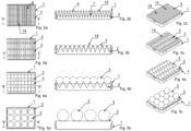
- the plant container 1 with a foldable planting surface 2 is shown schematically from the germination phase to the plant ready for harvest.
- Figure 1a shows the rectangular plant container 1, which is preferably made of plastic and is designed to be liquid-tight and light-tight.
- a foldable planting surface 2 which consists of individual folds 4.
- the foldability of the planting surface 2 makes it expandable, i.e. the planting surface can be made smaller and larger.
- the folds 4 are connected to one another and together form an elastic bellows.
- In the fold valley 5 there is an opening 9 for at least one plant 3.
- the opening 9 is designed to be large enough that the growing plant 3 is held and fixed by the planting surface 2.
- a receptacle 10 into which a substrate pad with a seed can be inserted.
- the receptacle 10 is designed, for example, in the shape of a basket or grid, so that the substrate in the receptacle 10 is in sufficient contact with the nutrient solution 15 beneath the planting surface 2 through the grid openings.
- Figure 1b shows the plant container 1 with the planting area 2, which has been pulled apart in the direction of the arrow 11. The distance between the folds 4 has thus been increased so that the grown plants 3 have more space and light. By pulling apart, the planting area is simultaneously raised in the direction of the arrow 12, which increases the distance 13 between the planting area 2 and the container base 16.
- Figure 1c shows the plant container 1 with a planting area 2 that is further apart. The distance 13 has increased further. The roots of the plants 3 are thus given more space beneath the planting area 2.
- Figure 1d shows the plant container 1 with the planting area 2 extended or expanded to the maximum.
- the plants 3 are no longer located between the folds 4, but lie on a flat planting area 2 and are therefore easy to harvest.
- the Figures 2a, 3a, 4a and 5a each show a top view of the plant container 1. From the top views it can be seen that the planting area 2 is designed as a module 14, whereby according to the Figure 2a a total of five modules 14 are arranged within the plant container 1. As the plants 3 grow, more and more modules 14 are removed from the plant container 1 and the remaining plant areas 2 in the plant container 1 are pulled further apart. This is done with the Figure 3a shown, in which only three modules 14 are in the plant container 1. According to the Figure 4a there are only two modules 14 in the plant container 1 and Figure 5a shows a plant container 1 with only one module 14 with a completely extended planting area 2.
- the Figures 2b, 3b, 4b and 5b correspond to the Figures 1a, 1b, 1c and 1d They show the plant containers 1 during the growth phase of the plants 3.
- the plant container 1 is shown in perspective during the growth phase of the plants 3.
- the perspective views show that the plants 3 are growing and therefore require more and more space.
- the necessary space is achieved by pulling apart the foldable planting area 2.
- individual, modular planting areas 3 can be removed from the plant container 1 and transferred to a new plant container 1.
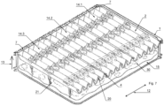
- FIG. 6 shows the plant container 1 in a sectional view.
- a total of five modules 14', 14", 14′′′, 14 ⁇ , 14′′′ ⁇ are arranged within the plant container 1.
- a module 14 consists of five webs 20, which are connected to the adjacent Folds 4 are connected.
- the webs 20 have the receptacles 10 for the plants 3.
- the receptacles 10 are designed like a basket, so that the individual roots 21 of the plants 3 extend through the basket-like receptacle 10 and are in contact with the nutrient solution 15, which is located in the area of the soil space 30.
- the plants 3 are thus located between two folds 4, which fix the plants 3.
- the folds 4 have a reflective surface with which the light is specifically reflected onto the plants 3.
- the plant container 1 has lateral guide devices 7 for the foldable planting surface 2.
- the guide device 7 is designed according to the Figure 6 designed as a rack, into which a rod 19 of the planting surface 2 engages.
- the guide device 7 allows the foldable planting surface 2 to be gradually pulled apart and pushed together, whereby the position of the planting surface 2 is fixed when the rod 19 engages between two teeth of the rack.
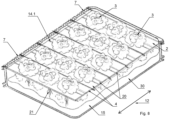
- FIG 7 shows the plant container 1 with a total of three modules 14', 14" and 14"'. Compared to the illustration of the Figure 6 A total of two modules 14 were removed from the plant container 1. This created additional space within the plant container 1 so that the remaining modules 14', 14" and 14′′′ can be pulled apart. The plants 3 thus have more space. By pulling the planting areas 3 apart in the direction of arrow 12, the distance 13 between the container bottom 16 and the openings 10 of the planting area 2 is simultaneously increased. This means that the floor space 30 is enlarged.
- FIG. 8 a plant container with only one module 14' is shown.
- the planting area 2 of the module 14' is completely pulled apart.
- the webs 20 and the adjacent folds 4 form a plane on which the plants 3 ready for harvest rest.
- the planting area 3 preferably has several rods 19 which engage in the rack-like guide device 7. The engagement or locking of the rods 19 in the guide device 7 prevents the planting area 3 from being accidentally contracted.
- the irrigation device 17 is designed as an ultrasonic atomizer and creates a mixture of air and the nutrient solution 15 below the planting area 2, which is absorbed by the roots 21 of the plants 3.
- the energy for the irrigation device 17 comes from an energy storage device 18.
- the energy storage device 18 is charged with energy via a media coupling 18.
- the energy storage device 18 makes the plant container 1 self-sufficient. This means that the plant container 1 only needs a light source while the plants 3 are being grown.
- the plant container 1 can also have several media couplings 18, via which, for example, the nutrient solution is refilled. It is also possible for the plant container 1 to have its own measuring device, with which, for example, the level of the nutrient solution, the temperature, the light intensity or the like is measured.
- the plant container 1 is shown with a foldable planting surface 2, which is designed as a module 14.
- the planting surface 2 consists of individual folds 4, which are connected to webs 19 via hinge connections. Two folds 4 and a web 19 together form a U-shaped planting row.
- the module 14 has a total of five rows of plants 24 arranged next to each other.
- the lateral guide devices 7 of the plant container 1 arrange the rows of plants 24 at a distance from the container bottom 16. This distance allows the roots 21 of the plants 3 to be optimally supplied with a mixture of air and the nutrient solution.
- the planting surface 3 has individual joints 23 which connect two folds 4 to one another.
- the joints 23 can have additional inserts through which the rods 19 for the guide device 7 are inserted.
- each fold tip 6 has an insert 2 so that the guidance of the planting surface 3 can be individually adjusted.
- Figure 11 shows the plant container 1 with several modules 14, as it is used, for example, in the germination phase of the plants 3.
- the Figure 11 are located many rows of plants 24 next to each other in the plant container 1. This means that many plants 3 can be illuminated with the same light source. This means that the space within the plant container 1 is used optimally and the electricity costs for lighting the plants can be saved.
- the plants 3 are located deep in the plant container 3 in this state of the rows of plants 24, so that the plants 3 are sufficiently in contact with the nutrient solution 15 located on the bottom 16 of the container.
- the folds 4 of the planting surface 3 are designed as plates 29 which are connected to one another by at least one hinge connection 23.
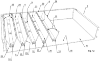
- Figure 12 shows the plant container 1 with a partially extended planting area 3. Two folds 4 and the web 20 between them together form a planting row 24. The first fold 4 and second fold 4 are partially opened at an angle 25. The planting rows 24 are connected to one another via hinge connections 23.
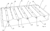
- Figure 13 shows the plant container 1 with a completely extended planting area 3.
- the folds 4 of the planting rows 23 are now opened by an angle 26.
- the angle 25 is larger than the angle 25 according to the Figure 12 .
- the transport robot 8 essentially consists of an approximately rectangular frame in which a central recess is arranged, which is bordered on both sides by two lifting devices lying opposite one another.
- a lifting platform can be raised and lowered from the central recess.
- Load-carrying devices are arranged on the lifting platform, which are designed as two telescopic arms spaced apart from one another, which can be moved in and out. With the help of the load-carrying devices, the plant containers 3 are gripped from below and pulled onto the surface of the lifting platform.
- the lifting platform can be pulled up by the lifting devices, so that the plant container 1 is then located in the interior of the transport robot 8 and the transport robot 8 moves to other places on the rail track 28 with the lifting platform raised.
- the module 14 of the foldable planting area 3 is inserted into or removed from the planting container 1 using the transport robot 8.
- the transport robot has a special gripping device.
- the plant container 1 according to the invention With the plant container 1 according to the invention with the foldable planting surface 3, it is now possible to illuminate more plants 3 on the same surface with one light source. This is achieved by the extendable planting surface 3, whereby the number of plant rows 24 can be adapted to the respective growth state and space requirements of the plants 3. Since the plants 3 are always in the same opening of the planting surface 3 during the entire growth phase, the roots 21 are not damaged. In addition, several plants 3 can be automatically removed from the plant container 3 at once and transferred to a new plant container 3.
- phase #1 the seeds for the plants 3 are in a substrate in the respective receptacles 10 of the planting area 2.
- the plant container 2 does not yet have a nutrient solution 16 or the like. In this state, the plant containers 2 can be stored for a longer period of time.
- the seeds of the plants 3 are activated as required by adding water or nutrient solution 15.
- Phase #2 shows the germination phase of the plants 3.
- a nutrient solution 15 which is at least partially in contact with the substrate or the plant 3 in the receptacle 10 of the planting area 2.
- an irrigation device 17 which creates a mixture of air and the nutrient solution 15.
- the plant containers 1 can now be brought into a shelf storage during the growth phase.
- Phase #3 shows the growth phases of the plants 3, whereby in the first, left plant container 1 there are still a total of five modules 14 of the planting area 2 due to the small size of the plants.
- the space required in the plant container 1 becomes ever larger, so that individual modules 14 are removed from the plant container 1 and the remaining modules 14 are pulled apart.
- the plants 3 in the planting area 2 are analyzed and, if necessary, nutrient solution 16 is refilled or individual Planting areas 2 are removed from the planting container 1. There are therefore only two modules 14 in the middle planting container 1.
- the right planting container 1 only has one module 14.
- the planting area 2 of the right planting container 1 is completely pulled apart.
- the plants 3 that are ready for harvest are now lying on the planting area 1.
- Phase #4 is the preparation phase, during which the plants 3 are harvested. After the plants 3 have been harvested, the plant containers 1 are washed and filled with new planting areas 2. The plant containers 1 are then stored again (see phase #1).
Landscapes
- Life Sciences & Earth Sciences (AREA)
- Environmental Sciences (AREA)
- Cultivation Receptacles Or Flower-Pots, Or Pots For Seedlings (AREA)
Claims (15)
- Dispositif de culture de plantes (3), constitué d'au moins une surface de plantation pliable (2), laquelle peut être disposée dans l'espace intérieur d'un contenant à plantes (1), dans lequel la surface de plantation (2) présente plusieurs plis (4) parallèles les uns aux autres, et dans la surface de plantation (2) sont présentes une pluralité d'ouvertures (9) disposées à distance les unes des autres dans lesquelles les plantes (3) peuvent être insérées, caractérisé en ce qu'à chaque fois, deux plis (4) parallèles réalisent une rangée de plantation (24) et les ouvertures (9) pour les plantes (3) sont entre les deux plis (4), et que la surface de plantation (2) pliable est étirable dans la direction horizontale (11), dans lequel la surface de plantation (2) est relevée par l'étirement et une distance (13) entre la surface de plantation (2) et un fond de contenant (16) du contenant à plantes (1) est augmentée.
- Dispositif selon la revendication 1, caractérisé en ce qu'il existe un angle (25, 26) entre les deux plis (4) adjacents, dans lequel l'angle (25, 26) entre les plis (4) adjacents est augmenté par l'étirement de la surface de plantation (2) et, dans le même temps, la distance verticale (13) entre le fond de contenant (16) du contenant à plantes (1) et la surface de plantation (2) est augmentée.
- Dispositif selon la revendication 1 ou 2, caractérisé en ce que le contenant à plantes (1) est réalisé en tant que contenant à plantes (1) transportable, ouvert d'un côté, délimité par des parois périphériques côté bord, dans l'espace de fond (30) duquel une solution nutritive (15) est disposée pour cultiver les plantes (3), dans lequel l'espace de fond (30) est recouvert au moins en partie vers le haut par la surface de plantation (2).
- Dispositif selon l'une des revendications 1 à 3, caractérisé en ce que plusieurs surfaces de plantation modulaires (2) à l'état plié peuvent être insérées avec les plantes (3) dans un contenant à plantes (1).
- Dispositif selon l'une des revendications 1 à 4, caractérisé en ce que la surface de plantation (2) est réalisée en tant que soufflet élastique.
- Dispositif selon l'une des revendications 1 à 4, caractérisé en ce que les plis (4) de la surface de plantation (2) sont réalisés en tant que plaques (29), lesquelles sont reliées les unes aux autres par au moins une liaison articulée (23).
- Dispositif selon l'une des revendications 1 à 4, caractérisé en ce que les plis (4) de la surface de plantation (2) sont réalisés en tant que plaques (29) et qu'une entretoise (20) comprenant les ouvertures (9) pour les plantes (3) est disposée entre deux plaques (29), dans lequel les plaques (29) et l'entretoise (29) sont mutuellement reliées par au moins une liaison articulée (23).
- Dispositif selon l'une des revendications 1 à 7, caractérisé en ce que la surface de plantation (2) est réalisée en tant que module (14), lequel peut être inséré dans le contenant à plantes (1) ou peut être enlevé du contenant à plantes (1).
- Dispositif selon l'une des revendications 1 à 8, caractérisé en ce que la surface de plantation (2) pliable est repliable et étirable dans la direction horizontale (11).
- Dispositif selon l'une des revendications 1 à 9, caractérisé en ce que la surface de plantation (2) pliable est installable par un robot de transport (8) dans le contenant à plantes (1), ou retirable de ce dernier, et/ou est repliable et/ou étirable par un robot de transport (8) dans la direction horizontale (11).
- Dispositif selon l'une des revendications 1 à 10, caractérisé en ce qu'au moins les plis (4) de la surface de plantation (2) présentent une surface réfléchissante.
- Dispositif selon l'une des revendications 1 à 11, caractérisé en ce que le contenant à plantes (1) présente au moins un dispositif de guidage (7) pour la surface de plantation (2).
- Procédé de culture de plantes (3), dans lequel au moins une surface de plantation (2) pliable présente plusieurs plis (4) parallèles les uns aux autres et dans la surface de plantation (2) sont présentes une pluralité d'ouvertures (9) disposées à distance les unes des autres dans lesquelles les plantes (3) peuvent être insérées, dans lequel la surface de plantation (2) peut être disposée dans l'espace intérieur d'un contenant à plantes (1) et est repliable et/ou étirable dans la direction horizontale (11), caractérisé en ce qu'à chaque fois, deux plis (4) parallèles réalisent une rangée de plantation (24) et les ouvertures (9) pour les plantes (3) sont entre les deux plis (4), et que la surface de plantation (2) pliable est étirable dans la direction horizontale (11), dans lequel la surface de plantation (2) est relevée par l'étirement et une distance (13) entre la surface de plantation (2) et un fond de contenant (16) du contenant à plantes (1) est augmentée.
- Procédé de culture de plantes (3), caractérisé en ce qu'un dispositif selon l'une des revendications 1 à 12 pour la culture de plantes (3) est utilisé dans le cas d'une agriculture verticale.
- Procédé de culture de plantes (3), dans lequel au moins une surface de plantation (2) pliable comprenant plusieurs plis (4) parallèles les uns aux autres est disposée dans un contenant à plantes (1) et une pluralité d'ouvertures (9) disposées à la distance les unes des autres dans lesquelles les plantes (3) sont
insérées se trouvent dans la surface de plantation (2), dans lequel dans la phase de croissance des plantes (3), des étapes de procédé suivantes sont effectuées :- agencer au moins deux surfaces de plantation (2) pliées en partie dans l'espace intérieur d'un premier contenant à plantes (1) ;- au fur et à mesure de la croissance des plantes (3), enlever le premier contenant à plantes (1) et transférer dans un deuxième contenant à plantes (1) au moins une surface de plantation (2) avec les plantes (3) insérées ;- étirer au moins partiellement l'au moins une surface de plantation (2) restante dans le premier contenant à plantes (1) dans la direction horizontale (11), dans lequel un angle (25, 26) entre les deux plis (4) adjacents est augmenté par l'étirement de la surface de plantation (2) et, dans le même temps, une distance verticale (13) entre le fond de contenant (16) du contenant à plantes (1) et la surface de plantation (2) est augmentée.
Applications Claiming Priority (1)
| Application Number | Priority Date | Filing Date | Title |
|---|---|---|---|
| DE102021107313.8A DE102021107313A1 (de) | 2021-03-24 | 2021-03-24 | Vorrichtung und Verfahren zur Aufzucht von Pflanzen |
Publications (3)
| Publication Number | Publication Date |
|---|---|
| EP4062749A1 EP4062749A1 (fr) | 2022-09-28 |
| EP4062749C0 EP4062749C0 (fr) | 2024-08-14 |
| EP4062749B1 true EP4062749B1 (fr) | 2024-08-14 |
Family
ID=80785019
Family Applications (1)
| Application Number | Title | Priority Date | Filing Date |
|---|---|---|---|
| EP22162387.9A Active EP4062749B1 (fr) | 2021-03-24 | 2022-03-16 | Dispositif et procédé de culture pour plantes |
Country Status (2)
| Country | Link |
|---|---|
| EP (1) | EP4062749B1 (fr) |
| DE (1) | DE102021107313A1 (fr) |
Cited By (2)
| Publication number | Priority date | Publication date | Assignee | Title |
|---|---|---|---|---|
| EP4725295A1 (fr) * | 2024-10-14 | 2026-04-15 | Heron Innovations Factory GmbH | Robot de transport pour la culture de plantes |
| EP4725296A1 (fr) * | 2024-10-14 | 2026-04-15 | Heron Innovations Factory GmbH | Stockage sur étagères pour la culture de plantes |
Families Citing this family (1)
| Publication number | Priority date | Publication date | Assignee | Title |
|---|---|---|---|---|
| EP4620295B1 (fr) | 2024-03-21 | 2026-02-11 | Heron Innovations Factory GmbH | Dispositif et procédé de croissance de plantes |
Family Cites Families (12)
| Publication number | Priority date | Publication date | Assignee | Title |
|---|---|---|---|---|
| IL69976A (en) * | 1983-10-16 | 1987-08-31 | Mekler Dan | Automatic planting apparatus and method |
| US5664370A (en) * | 1996-03-08 | 1997-09-09 | Jiffy Products Of America, Inc. | Plant growing tray |
| US20060053691A1 (en) | 2004-09-10 | 2006-03-16 | Harwood Edward D | Method and apparatus for aeroponic farming |
| US7872948B2 (en) | 2008-04-14 | 2011-01-18 | The Boeing Company | Acoustic wide area air surveillance system |
| CA2861881C (fr) | 2012-01-30 | 2019-12-03 | Affinor Growers Inc. | Procede et appareil d'horticulture et d'agriculture automatisees |
| CA2893563C (fr) | 2015-01-14 | 2020-04-07 | The Vista Institute LLC | Croissances de cryo-germinations |
| JP2017169493A (ja) | 2016-03-24 | 2017-09-28 | 昭和電工株式会社 | 植物栽培方法および植物栽培装置 |
| US10716265B2 (en) | 2017-01-16 | 2020-07-21 | Iron Ox, Inc. | Method for automatically redistributing plants throughout an agricultural facility |
| KR101898590B1 (ko) * | 2017-01-17 | 2018-09-13 | 엘지전자 주식회사 | 수경재배용 배드 조립체 |
| JP2018121550A (ja) | 2017-01-30 | 2018-08-09 | 博次 焼山 | 人工培地マット及びその製造方法 |
| DE102017121638A1 (de) | 2017-09-19 | 2019-03-21 | Heron Sondermaschinen Und Steuerungen Gmbh | Schienengebundener Transportroboter mit Hubplattform |
| DE102018109495B4 (de) | 2018-04-20 | 2022-10-13 | Heron Innovations Factory Gmbh | Transportroboter mit aufgeladenem Mehrachsroboter |
-
2021
- 2021-03-24 DE DE102021107313.8A patent/DE102021107313A1/de active Pending
-
2022
- 2022-03-16 EP EP22162387.9A patent/EP4062749B1/fr active Active
Cited By (2)
| Publication number | Priority date | Publication date | Assignee | Title |
|---|---|---|---|---|
| EP4725295A1 (fr) * | 2024-10-14 | 2026-04-15 | Heron Innovations Factory GmbH | Robot de transport pour la culture de plantes |
| EP4725296A1 (fr) * | 2024-10-14 | 2026-04-15 | Heron Innovations Factory GmbH | Stockage sur étagères pour la culture de plantes |
Also Published As
| Publication number | Publication date |
|---|---|
| EP4062749C0 (fr) | 2024-08-14 |
| DE102021107313A1 (de) | 2022-09-29 |
| EP4062749A1 (fr) | 2022-09-28 |
Similar Documents
| Publication | Publication Date | Title |
|---|---|---|
| EP3750398B1 (fr) | Dispositif et procédé pour stimuler la croissance de plantes | |
| EP3777519B1 (fr) | Procédé de fonctionnement automatisé d'une serre, dispositif d'alimentation et serre automatique | |
| DE68923877T2 (de) | Verfahren und vorrichtung für die hydroponkultur. | |
| EP4062749A1 (fr) | Dispositif et procédé de culture pour plantes | |
| DE2558574A1 (de) | Verfahren und vorrichtung zum aufziehen von pflanzen | |
| CH621234A5 (fr) | ||
| DE2351508A1 (de) | Verfahren und vorrichtung zum zuechten von pflanzen | |
| DE202010012739U1 (de) | Vorrichtung zur Aufzucht einer oder mehrerer Pflanzen | |
| EP4252528A1 (fr) | Support de plantes destiné à la culture de plantes et procédé de culture de plantes | |
| WO2012059155A1 (fr) | Procédé pour cultiver une ou plusieurs plantes | |
| EP4304331B1 (fr) | Système et procédé de culture de plantes dans un espace intérieur fermé | |
| DE2851201A1 (de) | Saatkasten zum ziehen und versetzen von pflanzen | |
| DE4302273C1 (de) | Vorrichtung zum Züchten von Pilzen, insbesondere Champignons | |
| DE3434486A1 (de) | Verfahren und anlage zum kultivieren von saprophytisch lebenden pilzen | |
| DE102014014244B4 (de) | Verfahren und Einrichtung zur Beerntung von aquatischen Pflanzenkulturen in gestapelten Kulturwannen | |
| WO2022018236A1 (fr) | Dispositif de culture pour plantes et cellule climatique à régulation climatique pour la culture de plantes à l'aide d'un dispositif de culture | |
| EP3883362B1 (fr) | Agencement pour serre | |
| EP4620295B1 (fr) | Dispositif et procédé de croissance de plantes | |
| DE102020125904A1 (de) | Trägersystem für eine automatisierte Aufzucht von Pflanzen | |
| EP4725296A1 (fr) | Stockage sur étagères pour la culture de plantes | |
| DE102018128968B3 (de) | Gewächshausanlage | |
| DE3707476A1 (de) | Verfahren und vorrichtung zum zuechten von pflanzen | |
| DE102022115528A1 (de) | Trägersystem zur Aufzucht von Pflanzen | |
| EP4537653A1 (fr) | Procédés et dispositifs de culture de plantes | |
| DE102023136690A1 (de) | System und Verfahren zur Bewirtschaftung einer landwirtschaftlichen Nutzfläche |
Legal Events
| Date | Code | Title | Description |
|---|---|---|---|
| PUAI | Public reference made under article 153(3) epc to a published international application that has entered the european phase |
Free format text: ORIGINAL CODE: 0009012 |
|
| STAA | Information on the status of an ep patent application or granted ep patent |
Free format text: STATUS: THE APPLICATION HAS BEEN PUBLISHED |
|
| AK | Designated contracting states |
Kind code of ref document: A1 Designated state(s): AL AT BE BG CH CY CZ DE DK EE ES FI FR GB GR HR HU IE IS IT LI LT LU LV MC MK MT NL NO PL PT RO RS SE SI SK SM TR |
|
| STAA | Information on the status of an ep patent application or granted ep patent |
Free format text: STATUS: REQUEST FOR EXAMINATION WAS MADE |
|
| 17P | Request for examination filed |
Effective date: 20221121 |
|
| RBV | Designated contracting states (corrected) |
Designated state(s): AL AT BE BG CH CY CZ DE DK EE ES FI FR GB GR HR HU IE IS IT LI LT LU LV MC MK MT NL NO PL PT RO RS SE SI SK SM TR |
|
| GRAP | Despatch of communication of intention to grant a patent |
Free format text: ORIGINAL CODE: EPIDOSNIGR1 |
|
| STAA | Information on the status of an ep patent application or granted ep patent |
Free format text: STATUS: GRANT OF PATENT IS INTENDED |
|
| INTG | Intention to grant announced |
Effective date: 20240405 |
|
| GRAS | Grant fee paid |
Free format text: ORIGINAL CODE: EPIDOSNIGR3 |
|
| GRAA | (expected) grant |
Free format text: ORIGINAL CODE: 0009210 |
|
| STAA | Information on the status of an ep patent application or granted ep patent |
Free format text: STATUS: THE PATENT HAS BEEN GRANTED |
|
| AK | Designated contracting states |
Kind code of ref document: B1 Designated state(s): AL AT BE BG CH CY CZ DE DK EE ES FI FR GB GR HR HU IE IS IT LI LT LU LV MC MK MT NL NO PL PT RO RS SE SI SK SM TR |
|
| REG | Reference to a national code |
Ref country code: GB Ref legal event code: FG4D Free format text: NOT ENGLISH |
|
| REG | Reference to a national code |
Ref country code: CH Ref legal event code: EP |
|
| REG | Reference to a national code |
Ref country code: DE Ref legal event code: R096 Ref document number: 502022001431 Country of ref document: DE |
|
| REG | Reference to a national code |
Ref country code: IE Ref legal event code: FG4D Free format text: LANGUAGE OF EP DOCUMENT: GERMAN |
|
| U01 | Request for unitary effect filed |
Effective date: 20240913 |
|
| U07 | Unitary effect registered |
Designated state(s): AT BE BG DE DK EE FI FR IT LT LU LV MT NL PT RO SE SI Effective date: 20241001 |
|
| PG25 | Lapsed in a contracting state [announced via postgrant information from national office to epo] |
Ref country code: NO Free format text: LAPSE BECAUSE OF FAILURE TO SUBMIT A TRANSLATION OF THE DESCRIPTION OR TO PAY THE FEE WITHIN THE PRESCRIBED TIME-LIMIT Effective date: 20241114 |
|
| PG25 | Lapsed in a contracting state [announced via postgrant information from national office to epo] |
Ref country code: PL Free format text: LAPSE BECAUSE OF FAILURE TO SUBMIT A TRANSLATION OF THE DESCRIPTION OR TO PAY THE FEE WITHIN THE PRESCRIBED TIME-LIMIT Effective date: 20240814 Ref country code: GR Free format text: LAPSE BECAUSE OF FAILURE TO SUBMIT A TRANSLATION OF THE DESCRIPTION OR TO PAY THE FEE WITHIN THE PRESCRIBED TIME-LIMIT Effective date: 20241115 |
|
| PG25 | Lapsed in a contracting state [announced via postgrant information from national office to epo] |
Ref country code: IS Free format text: LAPSE BECAUSE OF FAILURE TO SUBMIT A TRANSLATION OF THE DESCRIPTION OR TO PAY THE FEE WITHIN THE PRESCRIBED TIME-LIMIT Effective date: 20241214 |
|
| PG25 | Lapsed in a contracting state [announced via postgrant information from national office to epo] |
Ref country code: HR Free format text: LAPSE BECAUSE OF FAILURE TO SUBMIT A TRANSLATION OF THE DESCRIPTION OR TO PAY THE FEE WITHIN THE PRESCRIBED TIME-LIMIT Effective date: 20240814 |
|
| PG25 | Lapsed in a contracting state [announced via postgrant information from national office to epo] |
Ref country code: RS Free format text: LAPSE BECAUSE OF FAILURE TO SUBMIT A TRANSLATION OF THE DESCRIPTION OR TO PAY THE FEE WITHIN THE PRESCRIBED TIME-LIMIT Effective date: 20241114 Ref country code: ES Free format text: LAPSE BECAUSE OF FAILURE TO SUBMIT A TRANSLATION OF THE DESCRIPTION OR TO PAY THE FEE WITHIN THE PRESCRIBED TIME-LIMIT Effective date: 20240814 |
|
| PG25 | Lapsed in a contracting state [announced via postgrant information from national office to epo] |
Ref country code: RS Free format text: LAPSE BECAUSE OF FAILURE TO SUBMIT A TRANSLATION OF THE DESCRIPTION OR TO PAY THE FEE WITHIN THE PRESCRIBED TIME-LIMIT Effective date: 20241114 Ref country code: PL Free format text: LAPSE BECAUSE OF FAILURE TO SUBMIT A TRANSLATION OF THE DESCRIPTION OR TO PAY THE FEE WITHIN THE PRESCRIBED TIME-LIMIT Effective date: 20240814 Ref country code: NO Free format text: LAPSE BECAUSE OF FAILURE TO SUBMIT A TRANSLATION OF THE DESCRIPTION OR TO PAY THE FEE WITHIN THE PRESCRIBED TIME-LIMIT Effective date: 20241114 Ref country code: IS Free format text: LAPSE BECAUSE OF FAILURE TO SUBMIT A TRANSLATION OF THE DESCRIPTION OR TO PAY THE FEE WITHIN THE PRESCRIBED TIME-LIMIT Effective date: 20241214 Ref country code: HR Free format text: LAPSE BECAUSE OF FAILURE TO SUBMIT A TRANSLATION OF THE DESCRIPTION OR TO PAY THE FEE WITHIN THE PRESCRIBED TIME-LIMIT Effective date: 20240814 Ref country code: GR Free format text: LAPSE BECAUSE OF FAILURE TO SUBMIT A TRANSLATION OF THE DESCRIPTION OR TO PAY THE FEE WITHIN THE PRESCRIBED TIME-LIMIT Effective date: 20241115 Ref country code: ES Free format text: LAPSE BECAUSE OF FAILURE TO SUBMIT A TRANSLATION OF THE DESCRIPTION OR TO PAY THE FEE WITHIN THE PRESCRIBED TIME-LIMIT Effective date: 20240814 |
|
| PG25 | Lapsed in a contracting state [announced via postgrant information from national office to epo] |
Ref country code: SM Free format text: LAPSE BECAUSE OF FAILURE TO SUBMIT A TRANSLATION OF THE DESCRIPTION OR TO PAY THE FEE WITHIN THE PRESCRIBED TIME-LIMIT Effective date: 20240814 |
|
| PG25 | Lapsed in a contracting state [announced via postgrant information from national office to epo] |
Ref country code: CZ Free format text: LAPSE BECAUSE OF FAILURE TO SUBMIT A TRANSLATION OF THE DESCRIPTION OR TO PAY THE FEE WITHIN THE PRESCRIBED TIME-LIMIT Effective date: 20240814 |
|
| PG25 | Lapsed in a contracting state [announced via postgrant information from national office to epo] |
Ref country code: SK Free format text: LAPSE BECAUSE OF FAILURE TO SUBMIT A TRANSLATION OF THE DESCRIPTION OR TO PAY THE FEE WITHIN THE PRESCRIBED TIME-LIMIT Effective date: 20240814 |
|
| U20 | Renewal fee for the european patent with unitary effect paid |
Year of fee payment: 4 Effective date: 20250325 |
|
| PLBE | No opposition filed within time limit |
Free format text: ORIGINAL CODE: 0009261 |
|
| STAA | Information on the status of an ep patent application or granted ep patent |
Free format text: STATUS: NO OPPOSITION FILED WITHIN TIME LIMIT |
|
| 26N | No opposition filed |
Effective date: 20250515 |
|
| PGFP | Annual fee paid to national office [announced via postgrant information from national office to epo] |
Ref country code: CH Payment date: 20250401 Year of fee payment: 4 |
|
| PG25 | Lapsed in a contracting state [announced via postgrant information from national office to epo] |
Ref country code: MC Free format text: LAPSE BECAUSE OF FAILURE TO SUBMIT A TRANSLATION OF THE DESCRIPTION OR TO PAY THE FEE WITHIN THE PRESCRIBED TIME-LIMIT Effective date: 20240814 |
|
| PG25 | Lapsed in a contracting state [announced via postgrant information from national office to epo] |
Ref country code: IE Free format text: LAPSE BECAUSE OF NON-PAYMENT OF DUE FEES Effective date: 20250316 |
|
| REG | Reference to a national code |
Ref country code: CH Ref legal event code: U11 Free format text: ST27 STATUS EVENT CODE: U-0-0-U10-U11 (AS PROVIDED BY THE NATIONAL OFFICE) Effective date: 20260401 |
|
| U20 | Renewal fee for the european patent with unitary effect paid |
Year of fee payment: 5 Effective date: 20260327 |