EP4062954A1 - Enceinte amovible pour un dispositif de traitement de plaies par pression négative - Google Patents
Enceinte amovible pour un dispositif de traitement de plaies par pression négative Download PDFInfo
- Publication number
- EP4062954A1 EP4062954A1 EP21164071.9A EP21164071A EP4062954A1 EP 4062954 A1 EP4062954 A1 EP 4062954A1 EP 21164071 A EP21164071 A EP 21164071A EP 4062954 A1 EP4062954 A1 EP 4062954A1
- Authority
- EP
- European Patent Office
- Prior art keywords
- removable enclosure
- housing section
- sound
- enclosure according
- npwt
- Prior art date
- Legal status (The legal status is an assumption and is not a legal conclusion. Google has not performed a legal analysis and makes no representation as to the accuracy of the status listed.)
- Granted
Links
Images

Classifications
-
- A—HUMAN NECESSITIES
- A61—MEDICAL OR VETERINARY SCIENCE; HYGIENE
- A61M—DEVICES FOR INTRODUCING MEDIA INTO, OR ONTO, THE BODY; DEVICES FOR TRANSDUCING BODY MEDIA OR FOR TAKING MEDIA FROM THE BODY; DEVICES FOR PRODUCING OR ENDING SLEEP OR STUPOR
- A61M1/00—Suction or pumping devices for medical purposes; Devices for carrying-off, for treatment of, or for carrying-over, body-liquids; Drainage systems
- A61M1/80—Suction pumps
-
- A—HUMAN NECESSITIES
- A61—MEDICAL OR VETERINARY SCIENCE; HYGIENE
- A61M—DEVICES FOR INTRODUCING MEDIA INTO, OR ONTO, THE BODY; DEVICES FOR TRANSDUCING BODY MEDIA OR FOR TAKING MEDIA FROM THE BODY; DEVICES FOR PRODUCING OR ENDING SLEEP OR STUPOR
- A61M1/00—Suction or pumping devices for medical purposes; Devices for carrying-off, for treatment of, or for carrying-over, body-liquids; Drainage systems
- A61M1/90—Negative pressure wound therapy devices, i.e. devices for applying suction to a wound to promote healing, e.g. including a vacuum dressing
- A61M1/96—Suction control thereof
-
- A—HUMAN NECESSITIES
- A61—MEDICAL OR VETERINARY SCIENCE; HYGIENE
- A61M—DEVICES FOR INTRODUCING MEDIA INTO, OR ONTO, THE BODY; DEVICES FOR TRANSDUCING BODY MEDIA OR FOR TAKING MEDIA FROM THE BODY; DEVICES FOR PRODUCING OR ENDING SLEEP OR STUPOR
- A61M1/00—Suction or pumping devices for medical purposes; Devices for carrying-off, for treatment of, or for carrying-over, body-liquids; Drainage systems
- A61M1/90—Negative pressure wound therapy devices, i.e. devices for applying suction to a wound to promote healing, e.g. including a vacuum dressing
- A61M1/98—Containers specifically adapted for negative pressure wound therapy
- A61M1/984—Containers specifically adapted for negative pressure wound therapy portable on the body
-
- F—MECHANICAL ENGINEERING; LIGHTING; HEATING; WEAPONS; BLASTING
- F04—POSITIVE - DISPLACEMENT MACHINES FOR LIQUIDS; PUMPS FOR LIQUIDS OR ELASTIC FLUIDS
- F04B—POSITIVE-DISPLACEMENT MACHINES FOR LIQUIDS; PUMPS
- F04B43/00—Machines, pumps, or pumping installations having flexible working members
- F04B43/02—Machines, pumps, or pumping installations having flexible working members having plate-like flexible members, e.g. diaphragms
-
- F—MECHANICAL ENGINEERING; LIGHTING; HEATING; WEAPONS; BLASTING
- F04—POSITIVE - DISPLACEMENT MACHINES FOR LIQUIDS; PUMPS FOR LIQUIDS OR ELASTIC FLUIDS
- F04B—POSITIVE-DISPLACEMENT MACHINES FOR LIQUIDS; PUMPS
- F04B43/00—Machines, pumps, or pumping installations having flexible working members
- F04B43/12—Machines, pumps, or pumping installations having flexible working members having peristaltic action
-
- F—MECHANICAL ENGINEERING; LIGHTING; HEATING; WEAPONS; BLASTING
- F04—POSITIVE - DISPLACEMENT MACHINES FOR LIQUIDS; PUMPS FOR LIQUIDS OR ELASTIC FLUIDS
- F04B—POSITIVE-DISPLACEMENT MACHINES FOR LIQUIDS; PUMPS
- F04B53/00—Component parts, details or accessories not provided for in, or of interest apart from, groups F04B1/00 - F04B23/00 or F04B39/00 - F04B47/00
- F04B53/16—Casings; Cylinders; Cylinder liners or heads; Fluid connections
-
- A—HUMAN NECESSITIES
- A61—MEDICAL OR VETERINARY SCIENCE; HYGIENE
- A61M—DEVICES FOR INTRODUCING MEDIA INTO, OR ONTO, THE BODY; DEVICES FOR TRANSDUCING BODY MEDIA OR FOR TAKING MEDIA FROM THE BODY; DEVICES FOR PRODUCING OR ENDING SLEEP OR STUPOR
- A61M2205/00—General characteristics of the apparatus
- A61M2205/42—Reducing noise
-
- A—HUMAN NECESSITIES
- A61—MEDICAL OR VETERINARY SCIENCE; HYGIENE
- A61M—DEVICES FOR INTRODUCING MEDIA INTO, OR ONTO, THE BODY; DEVICES FOR TRANSDUCING BODY MEDIA OR FOR TAKING MEDIA FROM THE BODY; DEVICES FOR PRODUCING OR ENDING SLEEP OR STUPOR
- A61M2205/00—General characteristics of the apparatus
- A61M2205/58—Means for facilitating use, e.g. by people with impaired vision
- A61M2205/581—Means for facilitating use, e.g. by people with impaired vision by audible feedback
Definitions
- the present disclosure generally relates to a removable enclosure for a mobile negative pressure wound therapy (NPWT) device, where the enclosure is arranged to reduce unwanted noise from a pump comprised with the negative pressure pump.
- the enclosure is specifically useful when operating the NPWT device during nighttime.
- Negative pressure wound therapy is a technique that promotes healing of e.g. surgical, acute, and chronic wounds by the application of a sub-atmospheric pressure to the wound, using a negative pressure pump.
- the NPWT technique also permits less outside disturbance of the wound as well as for transportation of excess fluids away from the wound site.
- the NPWT technique has until now mainly been applied to a patient while in a hospital environment.
- recent product development now allows the technique to be used by a patient in a home environment.
- NPWT device When an NPWT device is used in such a home environment, it may be possible that the NPWT device is not operated and monitored by professional users, as compared to when the NPWT device is used in the mentioned hospital environment. Thus, it is desirable to further simplify the operational use of the NPWT device, for minimizing any errors in use and handling.
- Introducing the NPWT device in the home environment may in some situations have further implications on the patient and/or e.g. a partner of the patient. Specifically, when the negative pressure pump is operating, the pump may generate a noise that may be perceived as disturbing for the patient and/or the partner of the patient.
- a direct current (DC) motor-driven pump comprised within a housing of the NPWT device is operated to achieve the negative pressure.
- a vibration damping tape e.g., visco-elastic damping tape
- the pump may also be contained within a sub-housing arranged within the housing of the NPWT device, where the sub-housing may be hollow or formed entirely of open cell molded foam, e.g., used as a silencer to provide sound mitigation by reducing the sound energy of during operation of the pump.
- a removable enclosure for a mobile negative pressure wound therapy (NPWT) device comprising a negative pressure pump arranged within a housing of the NPWT device and connected to wound cover using a conduit
- the removable enclosure comprises a first housing section, and a second housing section, wherein the second housing section is arranged to join the first housing section to enclose the NPWT device
- the first and the second housing section each comprises an outer shell material and an inner insulation material
- at least one of the first or the second housing section is provided with an opening for passage of the conduit through a wall of the first housing section
- the second housing section is provided with a sound duct extending through the outer shell material and the inner insulation material
- the sound duct is positioned to propagate a sound emitted by a sound generating device comprised with the NPWT device to an outside of the removable enclosure, wherein the sound emitted by the sound generating device is indicative of a state of the NPW
- the present disclosure is based upon the realization that further measures are needed to ensure that the operation of the NPWT device does not disturb the patient and/or e.g. a partner of the patient. This is of specific importance during nighttime, when even in comparison low-level noise can be disturbing for the patient, and possibly the patient's partner if sharing the same bedroom.
- This is line with the present disclosure solved by providing the patient with a removable enclosure for the NPWT device, where the intention is to use the removable enclosure when the extra sound mitigation is needed. Nighttime usage of the removable enclosure is thus just an example of when such extra sound mitigation is advantageously applied.
- the combination of the forming the two housing sections from a combination of an outer shell material and an inner insulation material has surprisingly shown to greatly reduce the noise level of the NPWT device to such an extent that the patient and/or the partner of the patient do not perceived to be disturbed, even in a normal situation where the negative pressure pump is operation in an irregular manner (meaning that the noise level will be fluctuating over time).
- the inner insulation material it is generally desirable, but in some embodiments not absolutely necessary, to form the inner insulation material to match a shape of the NPWT device.
- the NPWT device will in such an embodiment have a "snug fit" to the inner insulation material, similar to how a camera may be positioned in a specifically adapted camera case.
- the combined insulation material for the first and the second housing section may in such an embodiment be formed to have a hollow portion towards the center of the removable enclosure, where the hollow portion matches the shape of the NPWT device.
- the operation of the NPWT device is in the mentioned home environment and not supervised by a skilled operator (such as e.g. a nighttime nurse), it is necessary to ensure that a sound indicative of a state of the NPWT device is still allowed to propagate to an outside of the removable enclosure.
- This is line with the present disclosure solved by introducing a sound duct extending through the outer shell material and the inner insulation material.
- the sound duct will thus at one end be positioned towards the NPWT device, and at the other end facing out of the removable enclosure.
- the end positioned towards the NPWT device is preferably arranged in relation to an area at the NPWT device where a volume of the sound generated by the sound generating device is as large as possible.
- Such an area may for example be defined by a sound outlet provided in a surface of the NPWT device, where the sound outlet possibly could be arranged to coincide with a position of the sound generating device at a printed circuit board (PCB) of the NPWT device.
- PCB printed circuit board
- the sound generating device may use a housing of the NPWT device to form part of the sound generating device. In such an embodiment it may thus be desirable to arrange the sound duct to engage and/or contact with the housing of the NPWT device.
- the first housing section and the second housing section are adapted to at least partly overlap and to completely encloses the NPWT device. It is of course necessary to ensure that the conduit is allowed to pass through e.g. a wall of the first and/or the second housing section of the removable enclosure. Thus, the conduit should not be interpreted as forming part of the NPWT device. Rather, the conduit forms together with the NPWT device and a wound cover part of a wound treatment system as will be discussed below in relation to the detailed description.
- each of the first and the second housing section may be an open box having five sides (an open top with a bottom and four walls).
- the second housing section may be made slightly larger as compared to the first housing section, where the openings are arranged towards each other when joined and where the first housing section is arranged partly within the second housing section.
- the first and the second housing section will thus together form a closed box, where one section can be seen as a lid and the other section as a bottom. It is as such desirable to arrange the lid to tightly fit to the bottom such that a minimal amount of noise is released at an interface between the bottom and the lid.
- the opening for passage conduit may be arranged as a slot within the wall of the first and/or second housing section of the removable enclosure.
- the opening within the wall may alternatively be formed as a slit or a notch.
- the slot/slit/notch is desirably selected to ensure that the conduit is not "squeezed".
- a squeezed conduit could potentially reduce a suction power of the NPWT device.
- a slot may be implemented with a desire to ensure that the NPWT device is "correctly" positioned within the removable enclosure, ensuring that the NPWT device is tightly fitted within the removable enclosure and align with possible hollow portions of the respective first and second housing sections.
- the outer shell material may generally be desirable to select the outer shell material to be of paper or plastic. From a cost perspective it may be suitable to select a paper material, such as for example of cardboard.
- An outer shell material formed as a sandwich structure comprising a paper interior has shown specifically suitable to provide the noise mitigating effects as desired in accordance to the present disclosure.
- a thickness of the outer shell material is at least 2 mm.
- the inner insulation material As mentioned above, it is generally desirable to form the inner insulation material to match the shape of the NPWT device, thereby maximizing a volume of the inner insulation material provided within the removable enclosure when the removable enclosure is closed around the NPWT device.
- One type of suitable inner insulation material is a polymer material, such as for example having a cell structure.
- a possible suitable inner insulation material may as such be a foam material.
- a thickness of the inner insulation material is at least 5 mm, preferably at least 10 mm.
- the thickness of the inner insulation material may also as an alternative be selected depending on desired amount of attenuation of the noise from the negative pressure pump during its operation.
- the attenuation of the noise from the negative pressure pump is at least 4 dBa, preferably at least 6 dBa.
- the sound duct extending through the outer shell material and the inner insulation material of the second housing section. It may in some embodiments be desirable to reduce any sound damping effect of the inner insulation material by arranging the sound duct to comprise a duct material that is selected to be different from the inner insulation material. That is, if for example the inner insulation material is a foam material, the foam material may dampen sound waves propagating through the sound duct. Arranging a wall of the sound duct to have more dense material properties may greatly reduce such a dampening effect.
- the duct material that is selected to be different from the inner insulation material should be interpreted in the broadest sense, also including an embodiment where a material property of the inner insulation material has been altered. As an example of such an alteration, it could for example be possible to heat treat the inner insulation material at a surface towards the sound duct.
- the sound duct material may also or instead comprise a paper or plastic tube section.
- a diameter of the sound duct is at least 2 mm, preferably at least 5 mm.
- the sound duct may have a circular cross section, but the cross section may of course be of any other shape (rectangular, triangular, etc.).
- the wound treatment system 100 further comprises a wound cover 104, the wound cover 104 being adapted to create a sealed space 106 defined in part by a wound surface 108, such as at the skin of a user/person, at or around a wound of the user/person.
- the NPWT device 102 is fluidly connected to the wound cover 104 using e.g. a conduit 110.
- the conduit 110 may be of any suitable flexible conduit fabricated from elastomeric and/or polymeric materials.
- the NPWT device 102 in turn comprises a negative pressure pump 112 adapted for establishing a negative pressure when the negative pressure pump 112 is operable, i.e. in an active state.
- the negative pressure pump 112 may be any type of pump that is biocompatible and maintains or draws adequate and therapeutic vacuum levels.
- the negative pressure level to be achieved is in a range between about -20 mmHg and about -300 mmHg.
- a negative pressure range between about -80 mmHg and about -140 mmHg is used.
- the negative pressure pump 112 is either a diaphragm pump or a peristaltic pump, or the like, in which the moving parts draw the mentioned fluid from the wound cover 104.
- the negative pressure pump 112 is fluidly connected to a canister 114, the canister 114 also forming part of the NPWT device 102.
- the canister 114 may be formed from e.g. molded plastic or the like, and possibly being a detachable component of the NPWT device 102.
- the canister 114 is preferably at least partly transparent/translucent to permit viewing into the interior of the canister 114 to assist the user in determining the remaining capacity of the canister 114.
- negative pressure generally refer to a pressure less than a local ambient pressure, such as the ambient pressure in a local environment external to a sealed therapeutic environment provided by a wound cover or dressing.
- the local ambient pressure may also be the atmospheric pressure at which a patient is located.
- values of pressure stated herein are gauge pressures.
- references to increases in negative pressure typically refer to a decrease in absolute pressure, while decreases in negative pressure typically refer to an increase in absolute pressure.
- An inlet port 116 is formed at the canister 114, for allowing connection to the conduit 110.
- the inlet port 116 may also be formed elsewhere at the NPWT device 102, however still fluidly connected to the canister 114.
- the connection between the inlet port 116 and the conduit 110 is a sealed connection, thus ensuring that no leakage is formed at the inlet port 116 during normal operation of the NPWT device 102.
- the conduit 110 is preferably releasably connected to the inlet port 116 through conventional means including a friction fit, bayonet coupling, snap fit, barbed connector, or the like.
- the inlet port 116 may be molded/formed from the same material and/or at the same time as forming the canister 114.
- the NPWT device 102 further comprises a battery 118 for powering the NPWT device 102.
- the battery 118 may preferably be of the rechargeable type but may alternatively be arranged to be disposable and thus to be changed once discharged.
- a specifically adapted battery pack may be used in relation to some embodiment of the present disclosure.
- the NPWT device 102 also comprises a control unit 120, electrically connected to the battery 118 and adapted to control an operation of the negative pressure pump 112.
- the control unit 120 may include a microprocessor, microcontroller, programmable digital signal processor or another programmable device.
- the control unit 120 may also, or instead, each include an application specific integrated circuit, a programmable gate array or programmable array logic, a programmable logic device, or a digital signal processor.
- the processor may further include computer executable code that controls operation of the programmable device.
- the NPWT device 102 further comprises a control circuitry 122 provided externally from the control unit 120 and arranged to generally control the operation of the negative pressure pump 112, specifically for ensuring that the operation of the negative pressure pump 112 may be swiftly terminated in case the NPWT device 102 starts to operate outside of what is considered to be a normal behavior, as has been discussed above.
- a control circuitry 122 provided externally from the control unit 120 and arranged to generally control the operation of the negative pressure pump 112, specifically for ensuring that the operation of the negative pressure pump 112 may be swiftly terminated in case the NPWT device 102 starts to operate outside of what is considered to be a normal behavior, as has been discussed above.
- the NPWT device 102 comprises at least one pressure sensor 126 arranged in fluid connection with the negative pressure pump 112.
- the wound cover 104 is arranged at a wound site of the user/patient, forming the sealed space 106.
- the conduit 110 is provided to fluidly connect the wound cover 104 to the inlet port 116 of the NPWT device 102.
- the NPWT device 102 is then activated, e.g. by the user/patient, for example by pressing a start button.
- the negative pressure pump 112 When activated, the negative pressure pump 112 will start to evacuate air through the canister 114, the inlet port 116, the conduit 110 and the sealed space 106 formed by the wound cover 104. Accordingly, the negative pressure will be created within the sealed space 106.
- this liquid from the wound site may at least partly be "drawn" from the wound site, through the conduit 110, the inlet port 116 and into the canister 114.
- the amount of liquid (possibly defined as exudate) that is drawn from the wound and collected in the canister will depend on the type of wound that is being treated as well as the type of wound dressing used. For example, in case an absorbent dressing is used, the liquid may be absorbed and collected both in the canister and the wound dressing, whereas if a dressing with no or little absorption capacity is used most or all of the liquid from the wound site may be collected in the canister.
- a suitable filter member (not shown in Fig. 1 ) is arranged between the canister 114 and the negative pressure pump 112 to ensure that no fluid is allowed to pass to the negative pressure pump 112 from the canister 114.
- the NPWT device may be void of a canister, wherein the negative pressure pump is fluidly connected to an absorbent dressing which function to absorb all liquid drawn from the wound.
- the NPWT device 102 may also, as indicated above comprise a speaker element 130 and thereto connected circuitry for driving the speaker element 130, where the speaker element 130 is connected to the control unit 120.
- the speaker element 130 is generally used for informing the patient of a specific state of the NPWT device 102, such as in case there is some form of problem relating to the operation of the NPWT device 102. Such an example may for example be an unwanted leakage in relation to the conduit 110 and/or the wound cover 104 or unwanted blockage of the conduit 110, where the unwanted leakage or blockage is identified by the control unit 120.
- the speaker element 130 will then be activated and adapted to play a specific and thereto related sound to inform the patient. Further possible dedicated informative sounds may relate to the canister 114 being full, the NPWT device 102 operating in an irregular manner, the battery 118 getting close to completely discharged, etc.
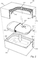
- the wound treatment system 100 comprises the removable enclosure 150 according to the present disclosure, for reducing a level of noise generated during operation of the NPWT device 102, such as when the negative pressure pump 112 is activated.
- the removable enclosure 150 comprises a first housing section 202 and a second housing section 204.
- the first housing section 202 is shown as a bottom portion of the removable enclosure 150 and the second housing section as a lid portion of the removable enclosure 150.
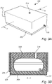
- the removable enclosure 150 is in Figs. 3A and 3B shown to have a rectangular shape with flat sides. It is of course possible to select any shape or form to achieve the desired effect according to the present disclosure.
- the first housing section 202 is formed from and comprises an outer shell material 206 made from paper and an inner insulation material 208 made from a polymer material that has a cell structure, such as a foam material.
- an outer shell material 206 made from paper
- an inner insulation material 208 made from a polymer material that has a cell structure, such as a foam material.
- Other materials may of course be used with the context and scope of the present disclosure.
- the inner insulation material 208 is in turn pre-cut or otherwise shaped (such as by molding) to correspond to a shape of the (bottom of the) NPWT device 102. As can be seen, the inner insulation material 208 is also pre-cut in relation to the conduit 110, and further provided with a slot 210 to allow the conduit 110 to pass through a wall of the first housing section 202.
- the second housing section 204, the lid portion of the removable enclosure 150, is also formed from and comprises a corresponding outer shell material 206 made from paper and a corresponding inner insulation material 208 made from a polymer material that has a cell structure, such as a foam material. It is of course possible to use different materials for the lid portion as compared to the bottom portion.
- the insulation material 208 of the second housing section 204 is also pre-cut or otherwise shaped to correspond to the shape of the (top of the) NPWT device 102. It may however, depending on the amount of inner insulation material 208 provided in relation to the first housing section 202 to allow the inner insulation material 208 to be essentially flat and to be slightly compressed when the first 202 and the second 204 housing sections are joined together.
- the second housing section 204 is provided with a slot 212, that matches the slot 210 of the first housing section 202 when the first 202 and the second 204 housing sections are joined together.
- the second housing section 204 is completely separate from the first housing section 202 and allowed to extend at an outer surface of the outer shell material 206 of the first housing section 202 when the housing sections are joined together, similar to a shoe box. It may however be possible to allow the housing sections to be partly joined at all time, e.g. arranging the second housing section 204 in a hinged manner as compared to the first housing section 202.
- the second housing section 204 is further provided with an elongated sound duct 214 that extends from an inside of the second housing section 204, through the inner insulation material 208 and out through the outer shell material 206.
- One end of the elongated sound duct 214 is specifically positioned in such a manner that it with a sound outlet position 220 at the NPWT device 102 where sound from the speaker element 130 is "outputted", as is specifically illustrated in Fig. 3 .
- Outputting the sound from the speaker element 130 may be dependent on the implementation selected for the NPWT device 102.
- the NPWT device 102 is provided with an opening 216 in a housing of the NPWT device 102.
- the speaker element 130 in the form of an actuator
- the housing of the NPWT device 102 will "vibrate” when the speaker element 130.
- the first end of the sound duct 214 it could be possible to arrange the first end of the sound duct 214 to be arranged to coincide with a suitable position of the housing of the NPWT device 102.
- the sound duct 214 is presented in a preferred embodiment where the sound duct 214 is kept as "short as possible” and perpendicular to a flat outer surface of the second housing section 204, thereby maximining the output of sound generated by the speaker element 130 to an outside of the removable enclosure 150. It is however possible to arrange the sound duct 214 in any other way to achieve the general desired effect of the present disclosure.
Landscapes
- Health & Medical Sciences (AREA)
- Engineering & Computer Science (AREA)
- Heart & Thoracic Surgery (AREA)
- Animal Behavior & Ethology (AREA)
- Anesthesiology (AREA)
- Biomedical Technology (AREA)
- Hematology (AREA)
- Life Sciences & Earth Sciences (AREA)
- Vascular Medicine (AREA)
- General Health & Medical Sciences (AREA)
- Public Health (AREA)
- Veterinary Medicine (AREA)
- Mechanical Engineering (AREA)
- General Engineering & Computer Science (AREA)
- External Artificial Organs (AREA)
- Percussion Or Vibration Massage (AREA)
Priority Applications (4)
| Application Number | Priority Date | Filing Date | Title |
|---|---|---|---|
| EP21164071.9A EP4062954B1 (fr) | 2021-03-22 | 2021-03-22 | Enceinte amovible pour un dispositif de traitement de plaies par pression négative |
| US18/550,149 US12016995B2 (en) | 2021-03-22 | 2022-03-14 | Removable enclosure for a negative pressure wound therapy device |
| PCT/EP2022/056547 WO2022200103A1 (fr) | 2021-03-22 | 2022-03-14 | Enceinte amovible pour dispositif de traitement de plaies par pression négative |
| CN202280021237.0A CN116981490B (zh) | 2021-03-22 | 2022-03-14 | 用于负压伤口治疗装置的可移除封壳 |
Applications Claiming Priority (1)
| Application Number | Priority Date | Filing Date | Title |
|---|---|---|---|
| EP21164071.9A EP4062954B1 (fr) | 2021-03-22 | 2021-03-22 | Enceinte amovible pour un dispositif de traitement de plaies par pression négative |
Publications (2)
| Publication Number | Publication Date |
|---|---|
| EP4062954A1 true EP4062954A1 (fr) | 2022-09-28 |
| EP4062954B1 EP4062954B1 (fr) | 2024-12-11 |
Family
ID=75143579
Family Applications (1)
| Application Number | Title | Priority Date | Filing Date |
|---|---|---|---|
| EP21164071.9A Active EP4062954B1 (fr) | 2021-03-22 | 2021-03-22 | Enceinte amovible pour un dispositif de traitement de plaies par pression négative |
Country Status (4)
| Country | Link |
|---|---|
| US (1) | US12016995B2 (fr) |
| EP (1) | EP4062954B1 (fr) |
| CN (1) | CN116981490B (fr) |
| WO (1) | WO2022200103A1 (fr) |
Citations (6)
| Publication number | Priority date | Publication date | Assignee | Title |
|---|---|---|---|---|
| US8257328B2 (en) | 2008-07-08 | 2012-09-04 | Tyco Healthcare Group Lp | Portable negative pressure wound therapy device |
| US20130110058A1 (en) * | 2011-11-02 | 2013-05-02 | Smith & Nephew Plc | Reduced pressure therapy apparatuses and methods of using same |
| WO2013171585A2 (fr) * | 2012-05-15 | 2013-11-21 | Smith & Nephew Plc | Appareil de thérapie pour plaies à pression négative |
| US20140343518A1 (en) * | 2011-11-28 | 2014-11-20 | Birgit Riesinger | Wound care device for treating wounds by means of subatmospheric pressure |
| US20190365966A1 (en) * | 2016-03-17 | 2019-12-05 | Medela Holding Ag | Medical suction pump |
| WO2020005532A1 (fr) * | 2018-06-25 | 2020-01-02 | Kci Licensing, Inc. | Procédé et système de réduction du bruit d'un dispositif médical portable |
Family Cites Families (13)
| Publication number | Priority date | Publication date | Assignee | Title |
|---|---|---|---|---|
| US20020134378A1 (en) * | 2001-03-26 | 2002-09-26 | Finnegan Linda A. | Sound dampening housing for respiratory assist devices |
| SK287803B6 (sk) * | 2001-06-08 | 2011-10-04 | Empresa Brasileira De Compressores S. A. - Embraco | Nasávací tlmič piestového hermetického kompresora |
| US6935459B2 (en) * | 2003-02-25 | 2005-08-30 | Stryker Instruments | Resonating device for a pneumatic surgical instrument |
| US7063134B2 (en) * | 2004-06-24 | 2006-06-20 | Tenneco Automotive Operating Company Inc. | Combined muffler/heat exchanger |
| DE102004040421A1 (de) * | 2004-08-19 | 2006-03-09 | J. Eberspächer GmbH & Co. KG | Aktiver Abgasschalldämpfer |
| JP2009519757A (ja) * | 2005-12-14 | 2009-05-21 | ストライカー・コーポレイション | 医療用/外科用廃棄物収集・処理システム |
| US8356733B2 (en) * | 2006-09-08 | 2013-01-22 | Medical Instill Technologies, Inc. | Method for dispensing fluids |
| US8127888B1 (en) * | 2011-02-02 | 2012-03-06 | Mann + Hummel, GmbH | Engine sound distribution apparatus for a motor vehicle |
| CN105492035B (zh) * | 2013-03-14 | 2019-06-14 | 史密夫和内修有限公司 | 用于应用减压治疗的系统和方法 |
| SG11201704255WA (en) * | 2014-12-22 | 2017-07-28 | Smith & Nephew | Negative pressure wound therapy apparatus and methods |
| EP3124059B1 (fr) * | 2015-07-28 | 2018-12-05 | Paul Hartmann AG | Amortisseur de bruit pour une unite de therapie a pression negative |
| CN211222322U (zh) * | 2019-09-24 | 2020-08-11 | 天津瑞祥纸制品有限公司 | 一种隔音纸板 |
| CN214387497U (zh) * | 2020-12-14 | 2021-10-15 | 河南省肿瘤医院 | 一种两用听诊器 |
-
2021
- 2021-03-22 EP EP21164071.9A patent/EP4062954B1/fr active Active
-
2022
- 2022-03-14 US US18/550,149 patent/US12016995B2/en active Active
- 2022-03-14 CN CN202280021237.0A patent/CN116981490B/zh active Active
- 2022-03-14 WO PCT/EP2022/056547 patent/WO2022200103A1/fr not_active Ceased
Patent Citations (6)
| Publication number | Priority date | Publication date | Assignee | Title |
|---|---|---|---|---|
| US8257328B2 (en) | 2008-07-08 | 2012-09-04 | Tyco Healthcare Group Lp | Portable negative pressure wound therapy device |
| US20130110058A1 (en) * | 2011-11-02 | 2013-05-02 | Smith & Nephew Plc | Reduced pressure therapy apparatuses and methods of using same |
| US20140343518A1 (en) * | 2011-11-28 | 2014-11-20 | Birgit Riesinger | Wound care device for treating wounds by means of subatmospheric pressure |
| WO2013171585A2 (fr) * | 2012-05-15 | 2013-11-21 | Smith & Nephew Plc | Appareil de thérapie pour plaies à pression négative |
| US20190365966A1 (en) * | 2016-03-17 | 2019-12-05 | Medela Holding Ag | Medical suction pump |
| WO2020005532A1 (fr) * | 2018-06-25 | 2020-01-02 | Kci Licensing, Inc. | Procédé et système de réduction du bruit d'un dispositif médical portable |
Also Published As
| Publication number | Publication date |
|---|---|
| CN116981490B (zh) | 2025-12-23 |
| US20240042121A1 (en) | 2024-02-08 |
| EP4062954B1 (fr) | 2024-12-11 |
| US12016995B2 (en) | 2024-06-25 |
| CN116981490A (zh) | 2023-10-31 |
| WO2022200103A1 (fr) | 2022-09-29 |
Similar Documents
| Publication | Publication Date | Title |
|---|---|---|
| US8845603B2 (en) | Silencer for vacuum system of a wound drainage apparatus | |
| US20030163101A1 (en) | Portable battery operated aspirator | |
| US12016995B2 (en) | Removable enclosure for a negative pressure wound therapy device | |
| WO2021059192A1 (fr) | Pompe à fluide médical à alarmes sonores | |
| WO2021053465A1 (fr) | Réduction de bruit pour des pompes dans des dispositifs de thérapie | |
| EP4342502B1 (fr) | Enceinte portable pour dispositif de traitement de plaies par pression négative | |
| JP2024510407A (ja) | 陰圧創傷療法装置 | |
| US20240091431A1 (en) | Negative pressure wound therapy systems and methods with multiple negative pressure sources | |
| US11931503B2 (en) | Mobile negative pressure wound therapy device with reduced pump noise | |
| US20050197640A1 (en) | Portable battery operated aspirator | |
| US20240407954A1 (en) | Negative pressure wound therapy system | |
| CN116981489A (zh) | 负压伤口治疗装置 |
Legal Events
| Date | Code | Title | Description |
|---|---|---|---|
| PUAI | Public reference made under article 153(3) epc to a published international application that has entered the european phase |
Free format text: ORIGINAL CODE: 0009012 |
|
| STAA | Information on the status of an ep patent application or granted ep patent |
Free format text: STATUS: THE APPLICATION HAS BEEN PUBLISHED |
|
| AK | Designated contracting states |
Kind code of ref document: A1 Designated state(s): AL AT BE BG CH CY CZ DE DK EE ES FI FR GB GR HR HU IE IS IT LI LT LU LV MC MK MT NL NO PL PT RO RS SE SI SK SM TR |
|
| STAA | Information on the status of an ep patent application or granted ep patent |
Free format text: STATUS: REQUEST FOR EXAMINATION WAS MADE |
|
| 17P | Request for examination filed |
Effective date: 20230327 |
|
| RBV | Designated contracting states (corrected) |
Designated state(s): AL AT BE BG CH CY CZ DE DK EE ES FI FR GB GR HR HU IE IS IT LI LT LU LV MC MK MT NL NO PL PT RO RS SE SI SK SM TR |
|
| GRAP | Despatch of communication of intention to grant a patent |
Free format text: ORIGINAL CODE: EPIDOSNIGR1 |
|
| STAA | Information on the status of an ep patent application or granted ep patent |
Free format text: STATUS: GRANT OF PATENT IS INTENDED |
|
| RIC1 | Information provided on ipc code assigned before grant |
Ipc: F04B 39/00 20060101ALI20240708BHEP Ipc: F04B 53/16 20060101ALI20240708BHEP Ipc: F04B 43/12 20060101ALI20240708BHEP Ipc: F04B 43/02 20060101ALI20240708BHEP Ipc: A61M 1/00 20060101AFI20240708BHEP |
|
| INTG | Intention to grant announced |
Effective date: 20240725 |
|
| GRAS | Grant fee paid |
Free format text: ORIGINAL CODE: EPIDOSNIGR3 |
|
| GRAA | (expected) grant |
Free format text: ORIGINAL CODE: 0009210 |
|
| STAA | Information on the status of an ep patent application or granted ep patent |
Free format text: STATUS: THE PATENT HAS BEEN GRANTED |
|
| AK | Designated contracting states |
Kind code of ref document: B1 Designated state(s): AL AT BE BG CH CY CZ DE DK EE ES FI FR GB GR HR HU IE IS IT LI LT LU LV MC MK MT NL NO PL PT RO RS SE SI SK SM TR |
|
| REG | Reference to a national code |
Ref country code: GB Ref legal event code: FG4D |
|
| REG | Reference to a national code |
Ref country code: CH Ref legal event code: EP |
|
| REG | Reference to a national code |
Ref country code: IE Ref legal event code: FG4D |
|
| REG | Reference to a national code |
Ref country code: DE Ref legal event code: R096 Ref document number: 602021023111 Country of ref document: DE |
|
| REG | Reference to a national code |
Ref country code: LT Ref legal event code: MG9D |
|
| PG25 | Lapsed in a contracting state [announced via postgrant information from national office to epo] |
Ref country code: HR Free format text: LAPSE BECAUSE OF FAILURE TO SUBMIT A TRANSLATION OF THE DESCRIPTION OR TO PAY THE FEE WITHIN THE PRESCRIBED TIME-LIMIT Effective date: 20241211 |
|
| PG25 | Lapsed in a contracting state [announced via postgrant information from national office to epo] |
Ref country code: FI Free format text: LAPSE BECAUSE OF FAILURE TO SUBMIT A TRANSLATION OF THE DESCRIPTION OR TO PAY THE FEE WITHIN THE PRESCRIBED TIME-LIMIT Effective date: 20241211 |
|
| PG25 | Lapsed in a contracting state [announced via postgrant information from national office to epo] |
Ref country code: BG Free format text: LAPSE BECAUSE OF FAILURE TO SUBMIT A TRANSLATION OF THE DESCRIPTION OR TO PAY THE FEE WITHIN THE PRESCRIBED TIME-LIMIT Effective date: 20241211 |
|
| REG | Reference to a national code |
Ref country code: NL Ref legal event code: MP Effective date: 20241211 |
|
| PG25 | Lapsed in a contracting state [announced via postgrant information from national office to epo] |
Ref country code: ES Free format text: LAPSE BECAUSE OF FAILURE TO SUBMIT A TRANSLATION OF THE DESCRIPTION OR TO PAY THE FEE WITHIN THE PRESCRIBED TIME-LIMIT Effective date: 20241211 |
|
| PG25 | Lapsed in a contracting state [announced via postgrant information from national office to epo] |
Ref country code: NO Free format text: LAPSE BECAUSE OF FAILURE TO SUBMIT A TRANSLATION OF THE DESCRIPTION OR TO PAY THE FEE WITHIN THE PRESCRIBED TIME-LIMIT Effective date: 20250311 |
|
| PG25 | Lapsed in a contracting state [announced via postgrant information from national office to epo] |
Ref country code: GR Free format text: LAPSE BECAUSE OF FAILURE TO SUBMIT A TRANSLATION OF THE DESCRIPTION OR TO PAY THE FEE WITHIN THE PRESCRIBED TIME-LIMIT Effective date: 20250312 Ref country code: LV Free format text: LAPSE BECAUSE OF FAILURE TO SUBMIT A TRANSLATION OF THE DESCRIPTION OR TO PAY THE FEE WITHIN THE PRESCRIBED TIME-LIMIT Effective date: 20241211 |
|
| PG25 | Lapsed in a contracting state [announced via postgrant information from national office to epo] |
Ref country code: RS Free format text: LAPSE BECAUSE OF FAILURE TO SUBMIT A TRANSLATION OF THE DESCRIPTION OR TO PAY THE FEE WITHIN THE PRESCRIBED TIME-LIMIT Effective date: 20250311 |
|
| PG25 | Lapsed in a contracting state [announced via postgrant information from national office to epo] |
Ref country code: NL Free format text: LAPSE BECAUSE OF FAILURE TO SUBMIT A TRANSLATION OF THE DESCRIPTION OR TO PAY THE FEE WITHIN THE PRESCRIBED TIME-LIMIT Effective date: 20241211 |
|
| REG | Reference to a national code |
Ref country code: AT Ref legal event code: MK05 Ref document number: 1749883 Country of ref document: AT Kind code of ref document: T Effective date: 20241211 |
|
| PG25 | Lapsed in a contracting state [announced via postgrant information from national office to epo] |
Ref country code: SM Free format text: LAPSE BECAUSE OF FAILURE TO SUBMIT A TRANSLATION OF THE DESCRIPTION OR TO PAY THE FEE WITHIN THE PRESCRIBED TIME-LIMIT Effective date: 20241211 |
|
| PG25 | Lapsed in a contracting state [announced via postgrant information from national office to epo] |
Ref country code: PL Free format text: LAPSE BECAUSE OF FAILURE TO SUBMIT A TRANSLATION OF THE DESCRIPTION OR TO PAY THE FEE WITHIN THE PRESCRIBED TIME-LIMIT Effective date: 20241211 |
|
| PG25 | Lapsed in a contracting state [announced via postgrant information from national office to epo] |
Ref country code: IS Free format text: LAPSE BECAUSE OF FAILURE TO SUBMIT A TRANSLATION OF THE DESCRIPTION OR TO PAY THE FEE WITHIN THE PRESCRIBED TIME-LIMIT Effective date: 20250411 |
|
| PG25 | Lapsed in a contracting state [announced via postgrant information from national office to epo] |
Ref country code: PT Free format text: LAPSE BECAUSE OF FAILURE TO SUBMIT A TRANSLATION OF THE DESCRIPTION OR TO PAY THE FEE WITHIN THE PRESCRIBED TIME-LIMIT Effective date: 20250411 |
|
| PG25 | Lapsed in a contracting state [announced via postgrant information from national office to epo] |
Ref country code: EE Free format text: LAPSE BECAUSE OF FAILURE TO SUBMIT A TRANSLATION OF THE DESCRIPTION OR TO PAY THE FEE WITHIN THE PRESCRIBED TIME-LIMIT Effective date: 20241211 |
|
| PG25 | Lapsed in a contracting state [announced via postgrant information from national office to epo] |
Ref country code: RO Free format text: LAPSE BECAUSE OF FAILURE TO SUBMIT A TRANSLATION OF THE DESCRIPTION OR TO PAY THE FEE WITHIN THE PRESCRIBED TIME-LIMIT Effective date: 20241211 Ref country code: AT Free format text: LAPSE BECAUSE OF FAILURE TO SUBMIT A TRANSLATION OF THE DESCRIPTION OR TO PAY THE FEE WITHIN THE PRESCRIBED TIME-LIMIT Effective date: 20241211 |
|
| PG25 | Lapsed in a contracting state [announced via postgrant information from national office to epo] |
Ref country code: SK Free format text: LAPSE BECAUSE OF FAILURE TO SUBMIT A TRANSLATION OF THE DESCRIPTION OR TO PAY THE FEE WITHIN THE PRESCRIBED TIME-LIMIT Effective date: 20241211 |
|
| PG25 | Lapsed in a contracting state [announced via postgrant information from national office to epo] |
Ref country code: CZ Free format text: LAPSE BECAUSE OF FAILURE TO SUBMIT A TRANSLATION OF THE DESCRIPTION OR TO PAY THE FEE WITHIN THE PRESCRIBED TIME-LIMIT Effective date: 20241211 |
|
| PG25 | Lapsed in a contracting state [announced via postgrant information from national office to epo] |
Ref country code: IT Free format text: LAPSE BECAUSE OF FAILURE TO SUBMIT A TRANSLATION OF THE DESCRIPTION OR TO PAY THE FEE WITHIN THE PRESCRIBED TIME-LIMIT Effective date: 20241211 |
|
| PG25 | Lapsed in a contracting state [announced via postgrant information from national office to epo] |
Ref country code: SE Free format text: LAPSE BECAUSE OF FAILURE TO SUBMIT A TRANSLATION OF THE DESCRIPTION OR TO PAY THE FEE WITHIN THE PRESCRIBED TIME-LIMIT Effective date: 20241211 |
|
| REG | Reference to a national code |
Ref country code: DE Ref legal event code: R097 Ref document number: 602021023111 Country of ref document: DE |
|
| PG25 | Lapsed in a contracting state [announced via postgrant information from national office to epo] |
Ref country code: DK Free format text: LAPSE BECAUSE OF FAILURE TO SUBMIT A TRANSLATION OF THE DESCRIPTION OR TO PAY THE FEE WITHIN THE PRESCRIBED TIME-LIMIT Effective date: 20241211 |
|
| PG25 | Lapsed in a contracting state [announced via postgrant information from national office to epo] |
Ref country code: MC Free format text: LAPSE BECAUSE OF FAILURE TO SUBMIT A TRANSLATION OF THE DESCRIPTION OR TO PAY THE FEE WITHIN THE PRESCRIBED TIME-LIMIT Effective date: 20241211 |
|
| PLBE | No opposition filed within time limit |
Free format text: ORIGINAL CODE: 0009261 |
|
| STAA | Information on the status of an ep patent application or granted ep patent |
Free format text: STATUS: NO OPPOSITION FILED WITHIN TIME LIMIT |
|
| REG | Reference to a national code |
Ref country code: CH Ref legal event code: L10 Free format text: ST27 STATUS EVENT CODE: U-0-0-L10-L00 (AS PROVIDED BY THE NATIONAL OFFICE) Effective date: 20251022 |
|
| REG | Reference to a national code |
Ref country code: CH Ref legal event code: H13 Free format text: ST27 STATUS EVENT CODE: U-0-0-H10-H13 (AS PROVIDED BY THE NATIONAL OFFICE) Effective date: 20251023 |
|
| PG25 | Lapsed in a contracting state [announced via postgrant information from national office to epo] |
Ref country code: LU Free format text: LAPSE BECAUSE OF NON-PAYMENT OF DUE FEES Effective date: 20250322 |
|
| 26N | No opposition filed |
Effective date: 20250912 |
|
| REG | Reference to a national code |
Ref country code: BE Ref legal event code: MM Effective date: 20250331 |
|
| PG25 | Lapsed in a contracting state [announced via postgrant information from national office to epo] |
Ref country code: BE Free format text: LAPSE BECAUSE OF NON-PAYMENT OF DUE FEES Effective date: 20250331 |
|
| PG25 | Lapsed in a contracting state [announced via postgrant information from national office to epo] |
Ref country code: CH Free format text: LAPSE BECAUSE OF NON-PAYMENT OF DUE FEES Effective date: 20250331 |
|
| PG25 | Lapsed in a contracting state [announced via postgrant information from national office to epo] |
Ref country code: IE Free format text: LAPSE BECAUSE OF NON-PAYMENT OF DUE FEES Effective date: 20250322 |
|
| PGFP | Annual fee paid to national office [announced via postgrant information from national office to epo] |
Ref country code: GB Payment date: 20260319 Year of fee payment: 6 |
|
| PGFP | Annual fee paid to national office [announced via postgrant information from national office to epo] |
Ref country code: DE Payment date: 20260320 Year of fee payment: 6 |
|
| PGFP | Annual fee paid to national office [announced via postgrant information from national office to epo] |
Ref country code: FR Payment date: 20260323 Year of fee payment: 6 |