EP4062964A1 - Quetschklemmenvorrichtung - Google Patents
Quetschklemmenvorrichtung Download PDFInfo
- Publication number
- EP4062964A1 EP4062964A1 EP22173613.5A EP22173613A EP4062964A1 EP 4062964 A1 EP4062964 A1 EP 4062964A1 EP 22173613 A EP22173613 A EP 22173613A EP 4062964 A1 EP4062964 A1 EP 4062964A1
- Authority
- EP
- European Patent Office
- Prior art keywords
- pinch clamp
- arm
- pinch
- clamp
- clamping
- Prior art date
- Legal status (The legal status is an assumption and is not a legal conclusion. Google has not performed a legal analysis and makes no representation as to the accuracy of the status listed.)
- Pending
Links
- 239000002861 polymer material Substances 0.000 abstract description 34
- 239000004033 plastic Substances 0.000 abstract description 14
- 229920003023 plastic Polymers 0.000 abstract description 14
- 238000001990 intravenous administration Methods 0.000 abstract description 5
- 230000002028 premature Effects 0.000 abstract description 4
- 238000005299 abrasion Methods 0.000 abstract description 3
- 230000007794 irritation Effects 0.000 abstract description 3
- 239000000463 material Substances 0.000 description 25
- 230000002265 prevention Effects 0.000 description 18
- 239000012530 fluid Substances 0.000 description 17
- 238000006073 displacement reaction Methods 0.000 description 15
- 238000000034 method Methods 0.000 description 8
- 230000008569 process Effects 0.000 description 7
- 238000007906 compression Methods 0.000 description 6
- 230000006835 compression Effects 0.000 description 5
- 230000008901 benefit Effects 0.000 description 4
- 230000003993 interaction Effects 0.000 description 3
- 238000002955 isolation Methods 0.000 description 3
- 229920000642 polymer Polymers 0.000 description 3
- 239000000853 adhesive Substances 0.000 description 2
- 230000001070 adhesive effect Effects 0.000 description 2
- 238000001125 extrusion Methods 0.000 description 2
- 210000003811 finger Anatomy 0.000 description 2
- 238000002347 injection Methods 0.000 description 2
- 239000007924 injection Substances 0.000 description 2
- 238000004519 manufacturing process Methods 0.000 description 2
- 238000000465 moulding Methods 0.000 description 2
- 239000007779 soft material Substances 0.000 description 2
- 229920002725 thermoplastic elastomer Polymers 0.000 description 2
- 210000003813 thumb Anatomy 0.000 description 2
- 239000004433 Thermoplastic polyurethane Substances 0.000 description 1
- 239000011248 coating agent Substances 0.000 description 1
- 238000000576 coating method Methods 0.000 description 1
- 229920001577 copolymer Polymers 0.000 description 1
- 229920006037 cross link polymer Polymers 0.000 description 1
- 239000003814 drug Substances 0.000 description 1
- 229940079593 drug Drugs 0.000 description 1
- 229920001971 elastomer Polymers 0.000 description 1
- 229920006341 elastomeric alloy Polymers 0.000 description 1
- 238000001746 injection moulding Methods 0.000 description 1
- 239000000203 mixture Substances 0.000 description 1
- 229920000098 polyolefin Polymers 0.000 description 1
- 238000011084 recovery Methods 0.000 description 1
- 239000005060 rubber Substances 0.000 description 1
- 229920006132 styrene block copolymer Polymers 0.000 description 1
- 238000004381 surface treatment Methods 0.000 description 1
- 229920006344 thermoplastic copolyester Polymers 0.000 description 1
- 229920006345 thermoplastic polyamide Polymers 0.000 description 1
- 229920002803 thermoplastic polyurethane Polymers 0.000 description 1
- 230000007704 transition Effects 0.000 description 1
- 230000000007 visual effect Effects 0.000 description 1
Images


Classifications
-
- A—HUMAN NECESSITIES
- A61—MEDICAL OR VETERINARY SCIENCE; HYGIENE
- A61M—DEVICES FOR INTRODUCING MEDIA INTO, OR ONTO, THE BODY; DEVICES FOR TRANSDUCING BODY MEDIA OR FOR TAKING MEDIA FROM THE BODY; DEVICES FOR PRODUCING OR ENDING SLEEP OR STUPOR
- A61M25/00—Catheters; Hollow probes
-
- A—HUMAN NECESSITIES
- A61—MEDICAL OR VETERINARY SCIENCE; HYGIENE
- A61M—DEVICES FOR INTRODUCING MEDIA INTO, OR ONTO, THE BODY; DEVICES FOR TRANSDUCING BODY MEDIA OR FOR TAKING MEDIA FROM THE BODY; DEVICES FOR PRODUCING OR ENDING SLEEP OR STUPOR
- A61M39/00—Tubes, tube connectors, tube couplings, valves, access sites or the like, specially adapted for medical use
- A61M39/22—Valves or arrangement of valves
- A61M39/28—Clamping means for squeezing flexible tubes, e.g. roller clamps
- A61M39/288—Clamping means for squeezing flexible tubes, e.g. roller clamps by bending or twisting the tube
-
- A—HUMAN NECESSITIES
- A61—MEDICAL OR VETERINARY SCIENCE; HYGIENE
- A61M—DEVICES FOR INTRODUCING MEDIA INTO, OR ONTO, THE BODY; DEVICES FOR TRANSDUCING BODY MEDIA OR FOR TAKING MEDIA FROM THE BODY; DEVICES FOR PRODUCING OR ENDING SLEEP OR STUPOR
- A61M39/00—Tubes, tube connectors, tube couplings, valves, access sites or the like, specially adapted for medical use
- A61M39/22—Valves or arrangement of valves
- A61M39/28—Clamping means for squeezing flexible tubes, e.g. roller clamps
- A61M39/284—Lever clamps
-
- A—HUMAN NECESSITIES
- A61—MEDICAL OR VETERINARY SCIENCE; HYGIENE
- A61M—DEVICES FOR INTRODUCING MEDIA INTO, OR ONTO, THE BODY; DEVICES FOR TRANSDUCING BODY MEDIA OR FOR TAKING MEDIA FROM THE BODY; DEVICES FOR PRODUCING OR ENDING SLEEP OR STUPOR
- A61M5/00—Devices for bringing media into the body in a subcutaneous, intra-vascular or intramuscular way; Accessories therefor, e.g. filling or cleaning devices, arm-rests
- A61M5/14—Infusion devices, e.g. infusing by gravity; Blood infusion; Accessories therefor
Definitions
- the pinch clamp is a well-known type of one-piece plastic clamp which is used to close off plastic tubing, such as intravenous tubing.
- the pinch clamp generally comprises a smooth, hard plastic material that is resilient and capable of controlled flexion to enable engagement and disengagement of the clamping surfaces.
- the molding or extrusion process of manufacturing a pinch clamp generally results in the clamp having sharp edges which may scratch or otherwise irritate the patient with which the clamp is used. Further, the hard, smooth properties of the clamp's plastic create difficulty in grasping and manipulating the clamp during use, especially when the clamp becomes wet.
- a PRIOR ART pinch clamp 1 is shown in a closed or clamped configuration under a shear force.
- PRIOR ART pinch clamp 1 generally comprises a first arm 2 having a lip 3 configured to selectively engage a terminal end 5 of second arm 4.
- Clamp 1 is engaged in a clamping configuration when terminal end 5 is received by lip 3.
- lip 3 and terminal end 5 may prematurely disengage and release clamping pressure.
- the present invention relates to pinch-style clamps that are designed for use in clamping or occluding plastic tubing, such as intravenous tubing.
- the pinch clamp of the present invention addresses and overcomes various difficulties known to exist in prior art pinch clamps.
- some embodiments of the present invention comprise a soft material applied to various surfaces of the pinch clamp to 1) prevent abrasion or irritation to the patient, 2) increase friction between the pinch clamp and the user operating said pinch clamp, 3) increase friction between engaged surfaces of the pinch clamp to prevent premature or unintended disengagement of the clamp, and 4) increase friction between the outer surfaces of the tubing and the clamping surfaces of the clamp.
- Some embodiments of the present invention further comprise a dynamic clamping surface or interface that results in positive displacement of fluid in the tubing during the process of engaging the pinch clamp.
- some embodiments of the present invention comprise a first clamping surface that is planar and elongated, wherein the first clamping surface is configured to contact and support a first side of the tubing.
- the pinch clamp further comprises a second clamping surface that is angled and elongated, whereby the second clamping surface comprises a first being spaced from the first clamping surface at a first distance, and further comprises a second end spaced from the first clamping surface at a second distance, wherein the second distance is greater than the first distance.
- the first end of the second clamping surface contact a second side of the tubing to occlude a portion of the tubing interposed between the first clamping surface and the first end of the second clamping surface.
- the angled surface of the second clamping surface progressively occludes or clamps the tubing along the length of the first clamping surface, thereby positively displacing fluid within the tubing from the interface between the first and second clamping surfaces.
- the second end of the second clamping surface is also in contact with the second side of the tubing such that the tubing is occluded or clamped along the entire length of the first and second clamping surfaces.
- a pinch clamp device comprising a first arm having a first end comprising a lip and a second end comprising a first clamping surface; a second arm having a first end comprising a terminal end and a second end comprising a second clamping surface positioned opposite the first clamping surface; a hinge interconnecting the second end of the first arm and the second end of the second arm; and a material applied to at least one surface of the pinch clamp, the material having a Shore A durometer hardness of from approximately 15 to approximately 100.
- the at least one surface of the pinch clamp is an edge surface.
- the at least one surface of the pinch clamp is a right-angle surface. In some instances, the at least one surface of the pinch clamp is selected from the group consisting of the lip and the terminal end. Further, in some instances the at least one surface of the pinch clamp is selected from the group consisting of the first clamping surface and the second clamping surface.
- the pinch clamp device further comprises a plurality of ridges provided on a contact surface of the second arm in proximity to the terminal end.
- the at least one surface of the pinch clamp comprises the plurality of ridges.
- the at least one surface of the pinch clamp comprises an interface surface between the terminal end and the lip.
- the at least one surface of the pinch clamp comprises a contact surface of the pinch clamp.
- the at least one surface of the pinch clamp comprises an interface surface between the first and second clamping surfaces.
- the lip of the pinch clamp comprises a plurality of parallel ridges, each ridge being capable of retaining the terminal end.
- a pinch clamp device comprising a first arm having a first clamping surface comprising a planar, elongated surface for supporting a first side of a section of tubing; a second arm having a second clamping surface positioned opposite the first clamping surface and comprising an angled, elongated surface, the second clamping surface having a first end and a second end, the first end being spaced from the first clamping surface at a first distance and the second end being spaced from the first clamping surface at a second distance, the second distance being greater than the first distance; and a hinge interconnecting the first and second arms.
- first end of the second clamping surface is configured to contact a second side of the tubing prior to the second end of the second clamping surface contacting the second side of the tubing during a process of closing the pinch clamp to clamp the tubing.
- the second end of the second clamping surface is configured to contact the second side of the tubing when the first and second arms of the pinch clamp are fully engaged.
- the device further comprises a material applied to at least one surface of the pinch clamp, the material having a Shore A durometer hardness of from approximately 15 to approximately 100.
- the at least one surface is an interface between the pinch clamp and the tubing.
- the at least one surface is selected from the group consisting of the first clamping surface and the second clamping surface.
- the at least one surface is a contact surface of the pinch clamp.
- a pinch clamp device comprising a first arm having a first end comprising a lip and a second end comprising a first clamping surface, the first clamping surface comprising a planar, elongated surface for supporting a first side of a section of tubing; a second arm having a first end comprising a terminal end and a second end comprising a second clamping surface positioned opposite the first clamping surface, the second clamping surface comprising an angled, elongated surface; a hinge interconnecting the second end of the first arm and the second end of the second arm; and a material applied to at least one surface of the pinch clamp, the material having a Shore A durometer hardness of from approximately 15 to approximately 100.
- the second clamping surface comprises a first end and a second end, the first end being spaced from the first clamping surface at a first distance and the second end being spaced from the first clamping surface at a second distance, wherein the second distance is greater than the first distance.
- a pinch clamp device comprising a first arm having a first end comprising a lip and a second end comprising a first clamping surface; a second arm having a first end comprising a terminal end and a second end comprising a second clamping surface positioned opposite the first clamping surface; and a hinge interconnecting the second end of the first arm and the second end of the second arm.
- the pinch clamp device further comprises a nesting component comprising opposing sidewalls coupled together via an interconnect, the interconnect being sized to fit inside of the hinge and to position the opposing sidewalls outside and adjacent to the first and second arms.
- the nesting component further includes a raised feature on an interior surface of one or more of the opposing sidewalls, the raised feature contacting one or both of the first and second arms to limit rotation of the nesting component.
- one of the first or second clamping surfaces is formed as a recessed surface between raised surfaces.
- the pinch clamp device further comprises extensions that extend from opposing sides of one of the first or second arms.
- the extensions are coupled together via a rounded interconnect, the rounded interconnect forming an opening through which tubing passes between the extensions.
- the first end of the second arm includes a second hinge. In some instances, the second hinge allows the terminal end of the second arm to pivot towards the hinge that interconnects the first and second arm.
- the first or second arms includes extensions positioned on opposing sides of the arm and the other of the first or second arms includes an inner extension that inserts between the opposing extensions when the pinch clap device is engaged.
- the first arm includes raised surfaces positioned on each side of the first clamping surface, the second clamping surface inserting between the raised surfaces when the pinch clamp device is engages.
- the hinge forms an elliptical-shaped opening between the hinge and the first and second clamping surfaces.
- the outer edges of the first and second arms are rounded.
- the terminal end of the second arm forms an interface surface having ends that protrude outwardly beyond the rounded outer edges of the second arm.
- one of the first or second clamping surfaces includes lateral posts and the other of the first or second clamping surfaces includes recessed surfaces that are positioned between the lateral posts when the first and second clamping surfaces are engaged.
- the terminal end of the second arm forms an interface surface that includes outwardly facing recessed surfaces and the first arm includes inwardly facing lateral protrusions between which the recessed surfaces are positioned when the interface surface is secured under a ledge formed by the lip.
- the first arm includes a recessed section positioned below the first clamping surface, the device further comprising a lateral disengagement prevention component having a bottom section and two opposing arms that extend upwardly from opposite ends of the bottom section; wherein the recessed section is configured to accommodate the lateral disengagement prevention component such that the opposing arms are positioned overtop the second arm.
- each opposing arm includes an inward protrusion that extends from an inner surface of the arm, each inward protrusion being positioned such that a bottom surface of the inward protrusion contacts a top surface of the first arm when the bottom surface of the lateral disengagement prevention component is position within the recessed section.
- the present invention relates to pinch-style clamps that are designed for use in clamping or occluding plastic tubing, such as intravenous tubing.
- the pinch clamp of the present invention addresses and overcomes various difficulties known to exist in prior art pinch clamps.
- some embodiments of the present invention comprise a soft material applied to various surfaces of the pinch clamp to 1) prevent abrasion or irritation to the patient, 2) increase friction between the pinch clamp and the user operating said pinch clamp, 3) increase friction between engaged surfaces of the pinch clamp to prevent premature or unintended disengagement of the clamp, and 4) increase friction between the outer surfaces of the tubing and the clamping surfaces of the clamp.
- Some embodiments of the present invention further comprise a dynamic clamping surface or interface that results in positive displacement of fluid in the tubing during the process of engaging the pinch clamp.
- some embodiments of the present invention comprise a first clamping surface that is planar and elongated, wherein the first clamping surface is configured to contact and support a first side of the tubing.
- the pinch clamp further comprises a second clamping surface that is angled and elongated, whereby the second clamping surface comprises a first being spaced from the first clamping surface at a first distance, and further comprises a second end spaced from the first clamping surface at a second distance, wherein the second distance is greater than the first distance.
- the first end of the second clamping surface contact a second side of the tubing to occlude a portion of the tubing interposed between the first clamping surface and the first end of the second clamping surface.
- the angled surface of the second clamping surface progressively occludes or clamps the tubing along the length of the first clamping surface, thereby positively displacing fluid within the tubing from the interface between the first and second clamping surfaces.
- the second end of the second clamping surface is also in contact with the second side of the tubing such that the tubing is occluded or clamped along the entire length of the first and second clamping surfaces.
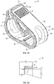
- FIG. 2A illustrates a perspective top and side view of a pinch clamp 10.
- Pinch clamp 10 generally comprises a first arm 12 having a first end comprising a lip 14 forming a ledge 15.
- lip 14 comprises a plurality of parallel ledges or ridges.
- First arm 12 further comprises a second end comprising a first clamping surface 16.
- first clamping surface 16 comprises a raised surface having a width that is approximately equal to a width of clamp 10.
- first clamping surface 16 is planar or generally flat.
- first clamping surface 16 is angled, rounded, pointed, ridged, grooved, or any combination thereof.
- Pinch clamp 10 further comprises a second arm 20 having a first end comprising a terminal end 24.
- Terminal end 24 is generally configured to engage with lip 14 to secure clamp 10 in an engaged configuration.
- terminal end 24 comprises a blunt, square end.
- terminal end 24 comprises a wedged or tapered shape, such that terminal end 24 tapers outwardly to a tip or pointed edge.
- Terminal end 24 further comprises an interface surface 22 that is configured to compatibly engage with ledge 15 of lip 14 so as to hold clamp 10 in an engaged configuration.
- second arm 20 comprises a second end having a second clamping surface 26.
- Second clamping surface 26 is generally positioned opposite of first clamping surface 16, as is common for pinch clamps.
- second clamping surface 26 is tapered such that in a disengaged configuration a first end of clamping surface 26 is spaced from clamping surface 16 at a first distance, and a second end of clamping surface 26 is spaced from clamping surface 16 at a second distance, the second distance being greater than the first distance.
- the second end of clamping surface 26 is closest to the first end 24 of second arm 20, and the first end of clamping surface 26 is in proximity to a closed end 32 of clamp 10.
- hinge 30 comprises a rounded extension of the second ends of first and second arms 12 and 20. Hinge 30 is configured to position first arm 12 opposite second arm 20.
- hinge 30 comprises a relaxed position (as shown in Figure 2 ) and a tensioned position (not shown). In the relaxed position, hinge 30 positions first and second arms 12 and 20 to provide a gap or space between first and second clamping surfaces 16 and 26. The relaxed position of hinge 30 further maintains a gap or space between terminal end 24 and lip 14.
- hinge 30 further comprises a window or opening 34 through which tubing is passed. First arm 12 further comprises a window or opening 36 that is generally aligned with window 34 and configured to accommodate tubing.
- a contact or exterior surface 26 of second arm 20 further comprises a grip feature 28.
- Grip feature 28 is generally provided to increase friction between a user's thumb or finger and pinch clamp 10 during use.
- grip feature 28 comprises a plurality of parallel ridges or raised features.
- grip feature 28 comprises a texture or other surface treatment intended to increase friction.
- grip feature 28 further provides a visual and/or tactile reference indicating how and where the user should grip the clamp 10.
- Some embodiments of the present invention further comprise a soft, polymer material 40 applied to various surfaces of pinch clamp 10.
- the term "soft, polymer material” is understood to include any material that may be applied or added to a plastic material suitable for use in manufacturing pinch clamp 10, wherein the soft, polymer material comprises a Shore A durometer hardness that is less than the plastic material of which the pinch clamp is constructed.
- a soft, polymer material comprises a Shore A durometer hardness of from approximately 15 to 100, from approximately 20 to 80, from approximately 30 to 70, from approximately 40 to 60, from approximately 45 to 55, or approximately 50.
- a soft, polymer material comprises a Shore A durometer hardness of less than 15.
- a soft, polymer material comprises a Shore A durometer hardness of greater than 100.
- Non-limiting examples of soft, polymer materials include thermoplastic elastomers such as thermoplastic rubbers, copolymers or physical mixes of polymers such as a plastic and a rubber, crosslinked polymers, styrenic block copolymers, polyolefin blends, elastomeric alloys, thermoplastic polyurethanes, thermoplastic copolyester, thermoplastic polyamides, or combinations thereof.
- thermoplastic elastomers such as thermoplastic rubbers, copolymers or physical mixes of polymers such as a plastic and a rubber, crosslinked polymers, styrenic block copolymers, polyolefin blends, elastomeric alloys, thermoplastic polyurethanes, thermoplastic copolyester, thermoplastic polyamides, or combinations thereof.
- a soft, polymer material is applied as a thin coating to the rigid or semi-rigid material of the pinch clamp.
- soft, polymer material pieces are first produced by a known process, such as extrusion or injection molding. The polymer pieces are then applied to one or more surfaces of the pinch clamp, such as by an adhesive, mechanical interference, or interlocking features or surfaces. In some instances, one or more surfaces of the rigid or semi-rigid material of the pinch clamp is removed and replaced by the polymer pieces to provide a final profile and shape for the pinch clamp.
- the pinch clamp is provided in a two-shot molding process, wherein a first injection unit is provided to mold the rigid or semi-rigid material of the clamp, and a second injection unit is provided to apply the soft, polymer material in strategic locations.
- a first injection unit is provided to mold the rigid or semi-rigid material of the clamp
- a second injection unit is provided to apply the soft, polymer material in strategic locations.
- one or more surfaces of the rigid or semi-rigid material of the pinch clamp is removed and replaced by the polymer material or pieces to soften one or more contact surfaces.
- one or more surfaces of the rigid or semi-rigid material of the pinch clamp is removed and replaced by the polymer material or pieces to increase friction between two or more surfaces of the clamp, or between one or more surfaces of the clamp and a section of tubing inserted within the clamp.
- a soft, polymer material 40 is applied to various surfaces of pinch clamp 10 to soften various surfaces of pinch clamp 10 that may otherwise scratch or irritate a patient's skin.
- a soft, polymer material 40 is applied to an edge or side surface 50 of pinch clamp 10.
- a soft, polymer material 40 is applied to a right-angled surface 52 of pinch clamp 10.
- a soft, polymer material 40 is applied to a contact surface, wherein a "contact surface" is understood to include any exposed surface that may contact a patient during use.
- a soft, polymer material 40 is applied to all exterior surfaces of pinch clamp 10.
- a soft, polymer material 40 is applied to various surfaces to increase friction.
- a soft, polymer material 40 is applied to a grip feature 28 of pinch clamp 10, whereby to increase friction between the user's thumb or finger and pinch clamp 10.
- a soft, polymer material 40 is applied to at least one of the first and second clamping surfaces 16 and 26, whereby to increase friction between the clamping surfaces and tubing secured therebetween.
- a soft, polymer material 40 is applied to at least one of lip 14 and terminal end 24 to increase friction therebetween.
- the hard plastic interface between lip 3 and terminal end 5 enables skewing of first and second arms 2 and 4 when a shear force 6 is applied to the clamp 1. This may result in premature or unintended disengagement of clamp 1.
- the soft, polymer material 40 interface between lip 15 and terminal end 24 increases friction between these surfaces, thereby preventing unintended disengagement. A detailed view of these surfaces is shown in Figure 2B .
- At least one surface of lip 15 and terminal end 24 further comprise a mechanical feature or surface 25 configured to further increase lateral or axial friction at interface surface 22, as shown in Figures 3A-3C .
- interface surface 22 has a mechanical feature 25 comprising a plurality of interlocking grooves.
- mechanical feature 25 provides alignment between first and second arms 14 and 20.
- mechanical feature 25 comprises micro-features, such as a texture.
- mechanical feature 25 comprises a micro-feature that is perpendicular, parallel, or perpendicular and parallel to the direction of tubing threaded through clamp 10.
- mechanical feature 25 is formed in the rigid polymer material of clamp 10, and subsequently coated or covered with a soft, polymer material 40. In other instances, mechanical feature 25 is provided directly in soft, polymer material 40.
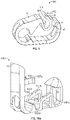
- some embodiments of the present invention comprise a dynamic clamping surface or interface 55 that results in positive displacement of fluid 60 within the tubing 70 being clamped.
- Positive displacement of fluid 60 may be desirable where fluid 60 comprises a medication that would remain in tubing 70 except for being advanced into the patient via positive displacement.
- pinch clamp 10 is shown in a disengaged configuration, whereby a first side 72 of tubing 70 is supported on the entire, elongated first clamping surface 16 of first arm 12. Further, a first end 27 of second clamping surface 26 is positioned in proximity to, or lightly in contact with a second side 74 of tubing 70.
- first clamping surface 16 is generally planar and elongated such that surface 16 supports a length of tubing 70.
- second clamping surface 26 is angled such that a first end 27 is positioned lower than, or closer to first clamping surface 16 that is the position of second end 29.
- second clamping surface tapers outwardly or upwardly from first end 27 to second end 29, or from the proximal end to the distal end of second clamping surface 26.
- Tubing 70 is not compressed or occluded when pinch clamp 10 is in a disengaged configuration. Rather, tubing 70 is freely moveable between first and second clamping surfaces 16 and 26.
- first and second clamping surfaces 16 and 26 further comprise a soft, polymer material (not shown) that increases friction between tubing 70 and the clamping surfaces such that pinch clamp 10 is prevented from freely sliding along the length of tubing 70. Rather, pinch clamp 10 must be manually adjusted by a user to a desired position on tubing 70, after which clamp 10 maintains its position by friction between the soft, polymer material and the outer surface of tubing 70.
- the soft, polymer material (not shown) further provides a cushioning function between the rigid plastic material of pinch clamp 10 and the pliable plastic material of tubing 70.
- this cushioning function enables full occlusion of tubing 70 while preventing hard kinking that may weaken the tubing structure. In some instances, this cushioning function improves tubing recovery upon release of pinch clamp 10.
- pinch clamp 10 is moved from a disengaged configuration to a partially engaged configuration as second arm 20 is moved in a downward direction 80 and tubing 70 is pinched between first end 27 of second clamping surface 26 and a proximal end of first clamping surface 16.
- tubing 70 is pinched between first end 27 of second clamping surface 26 and a proximal end of first clamping surface 16.
- first arm 20 is further advanced in downward direction 80, the distance between the remaining surfaces of second clamping surface 26 and first clamping surface 16 is gradually reduced as the second end 29 descends towards first clamping surface 16, as shown in Figure 4C .
- This gradual occlusion forces or positively displaces fluid 60 out from between the clamped surfaces thereby advancing fluid 60 through the distal section of tubing 70.
- the displaced fluid 60 is infused into a patient via an intravenous catheter coupled to tubing 70.
- First arm 20 is further advanced in downward direction 80 until distal end 24 is received by lip 14, thereby fully engaging pinch clamp 10, as discussed previously.
- tubing 70 is fully clamped between second end 29 of second clamping surface 26 and first clamping surface 16, as shown in Figure 4D .
- first end 27 and second end 29 are approximately equally distanced from first clamping surface 16 when pinch clamp 10 is fully engaged.
- the positive displacement of fluid 60 is complete.
- second arm 20 flexes or pivots about the contact point between first end 27 and first clamping surface 16, such that clamping pressure or contact between second clamping surface 26 and tubing 70 is applied in a linear fashion.
- hinge 30 is configured to bend and adjust laterally to facilitate linear application of compression force between first and second clamping surfaces 16 and 26.
- first and second clamping surfaces 16 and 26 further comprise a proximal end comprising or consisting of a rigid or semi-rigid material, and further comprising a distal end comprising or consisting of a soft, polymer material 40, as shown in Figure 5 .
- This embodiment has the benefit of providing a robust primary or proximal clamping interface, while having a softer distal clamping interface to compress the internal volume of the tubing, while preventing over-compression of the tubing over the full length of the clamping surface.
- the rigid or semi-rigid proximal end material further reduces friction between pinch clamp and tubing 70 when in the disengaged configuration, thereby permitting easy movement of clamp 10 along the length of tubing 70.
- tube 70 may exit pinch clamp 10 laterally between first and second arms 12 and 20. Accordingly, some embodiments of the present invention further provide one or more extensions 100 to retain a tube within pinch clamp 10, as shown in Figures 6A-6C . In some instances, a portion of the outer edge surface of first arm 12 is extended upwardly towards second arm 20 to provide a wall or extension 100, as shown in Figure 6A . In some instances, a portion of the outer edge surface of second arm 20 is extended downwardly towards first arm 12 to provide a wall or extension 100, as shown in Figure 6B . In some embodiments, pinch clamp 10 comprises two or more extensions 100.
- pinch clamp 10 comprises a first extension 100 on a first side of second arm 20, and a second extension 100 on a second side of second arm 20, wherein the second side is opposite the first side.
- pinch clamp 10 comprises a first and second extension 100 on opposite sides of first arm 12.
- pinch clamp 10 comprises first and second extensions on opposite sides of first arm 12, and further comprises first and second extensions 100 on opposite sides of second arm 20, wherein the extensions overlap, abut, or close a distance between one another when clamp 10 is in an engaged configuration.
- Extension 100 is configured to at least partially close the gap between first and second arms 12 and 20 when in the engaged or disengaged configurations.
- extension 100 is a thin fin or plate or rigid or semi-rigid material.
- extension 100 is a thin fin or plate of soft, polymer material 40.
- extension 100 is a thin fin or plate of rigid or semi-rigid material onto which is applied a soft, polymer material 40.
- the outward edges of first clamping surface 16 further comprises one or more extensions 100 that extend upwardly towards second clamping surface 26.
- the outer edges of second clamping surface 26 comprise one or more recesses or notches 110 configured to receive the one or more extensions 100 when pinch clamp 10 is engaged.
- extensions 100 and recesses 110 retains tube 70 within the clamping surfaces when clamp 10 is engaged.
- portions of the rigid or semi-rigid material of clamp 10 is removed and replaced by soft, polymer material 40 to provide one or more of first and second clamping surfaces 16 and 26, extensions 100, and recesses 110.
- FIGS 7A-12 illustrate a number of different variations of a pinch clamp in accordance with one or more embodiments of the present invention.
- Each of these pinch clamps includes the same general structure as pinch clamp 10. Therefore, many of the components of each pinch clamp will not be redundantly described. However, similar references will be employed to refer to these similar structures. Also, although the figures depict various specific embodiments that include one or more variations, these variations could be employed in addition to or in placed of features of any of the other described embodiments of pinch clamps.
- Figures 7A-7D illustrate an embodiment of a pinch clamp 700 that is similar to pinch clamp 10 but employs a nesting component 701 to prevent the lateral disengagement of second arm 20 from first arm 12.
- nesting component 701 can prevent relative movement between first arm 12 and second arm 20 in a direction that is substantially perpendicular to the longitudinal axis of the tubing to which pinch clamp 700 may be coupled.
- nesting component 701 pinch clamp 700 (or other similar embodiments of pinch clamps that include a nesting component) will likely only become disengaged when the clinician intentionally applies a downward/outward force on the terminal end of first arm 12.
- nesting component 701 comprises opposing sidewalls 701a that are coupled together via interconnect 701b.
- the width/diameter of interconnect 701b can be configured to allow the interconnect to sit within opening 712 formed between the hinge and clamping surfaces, while the length of interconnect 701b can be configured such that sidewalls 701a are positioned immediately outside the outer surfaces of first arm 12 and second arm 20.
- the size of sidewalls 701a i.e., the amount by which sidewalls 701a extend away from interconnect 701b in any direction
- Interconnect 701b can include an opening 701c that generally aligns with opening 34 to accommodate tubing that may extend through pinch clamp 700.
- one or both of the inner surfaces of sidewalls 701a can include a raised feature 701d that functions to limit rotation of nesting component 701 with respect to pinch clamp 700.
- sidewall 701a can have a size sufficient to cause raised feature 701d to be positioned on an opposite side of the clamping surfaces from interconnect 701b.
- Figure 7D illustrates how raised feature 701d would be positioned to cause the feature to contact an inside surface of first arm 12 or second arm 20 when nesting component 701 is rotated. In this way, raised feature 701d minimizes the likelihood that opening 701c may kink or otherwise occlude the tubing.
- Figure 7C which shows pinch clamp 700 without nesting component 701
- Figure 7D which illustrates a cross-sectional side view of pinch clamp 700 containing nesting component 701
- first clamping surface 16 and second clamping surface 26 include protrusions 710 and 711 respectively.
- protrusions 710 and 711 are shown at the left or proximal end of the clamping surfaces. Protrusions 710 and 711 function in a similar manner as the dynamic clamping surfaces depicted in Figures 4A-4D .
- pinch clamp 700 As pinch clamp 700 is engaged, protrusions 710 and 711 will contact the tubing prior to the remaining portions of first and second clamping surfaces 16 and 26. Accordingly, as pinch clamp 700 becomes fully engaged, fluid within the tubing will be forced in a distal direction (or in a rightward direction in Figure 7D ).
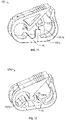
- Figures 8A and 8B illustrate another embodiment of a pinch clamp 800 that is similar to pinch clamp 10.
- first clamping surface 16 is formed as a recessed surface positioned between raised surfaces 801a and 801b. Accordingly, when pinch clamp 800 is engaged, second clamping surface 26 inserts between raised surfaces 801a and 801b to contact first clamping surface 16.
- pinch clamp 800 provides multiple points of compression on the tubing. More specifically, raised surfaces 801a and 801b can provide compression on tubing in a distal and proximal direction respectively. This "arc" of compression can enhance the occlusion of the tubing to minimize the likelihood that the tubing will not be fully occluded when pinch clamp 800 is engaged. Also, due to the respective angles between second clamping surface 26 and raised surface 801b, a degree of positive displacement may occur as the tubing is occluded.
- FIGs 8A and 8B also show that pinch clamp 800 can include extensions 802a and 802b.
- extensions 802a and 802b are shown as extending downwardly from the second arm.
- extensions 802a and 802b could equally extend upwardly from the first arm.
- extensions 802a and 802b can include a rounded interconnect 802c.
- Rounded interconnect 802c can generally conform to the shape of tubing so that the tubing is securely contained between extensions 802a and 802b when pinch clamp 800 is engaged. This secure containment can function to inhibit the lateral movement between the first and second arms of pinch clamp 800. More particularly, contact between extension 802a or 802b and the tubing will resist lateral movement of the second arm with respect to the first arm so that second arm cannot easily be moved laterally to the point of disengaging from the first arm.
- Figure 9 illustrates an embodiment of a pinch clamp 900 that employs a different configuration for the terminal end of second arm 20.
- pinch clamp 900 is configured such that the second arm is disengaged from the first arm by applying a force against the second arm that is in a generally proximal direction 910.
- second arm 20 includes a hinge 901 towards its distal end.
- a terminal end 902 of second arm 20 extends upwardly and proximally away from interface surface 22.
- interface surface 22 inserts under ledge 15 to engage the pinch clamp.
- a force in the proximal direction 910 can be applied to terminal end 902 rather than applying a force in a downward/distal direction on lip 14.
- pinch clamp 900 can be configured to include any of the positive displacement features and/or a nesting component as described above.
- FIGS 10A-10C illustrate another embodiment of a pinch clamp 1000.
- Pinch clamp 1000 includes protrusions 1003a and 1003b that extend upwardly from the first arm and protrusion 1004 that extends downwardly from the second arm.
- Protrusion 1004 can be configured to insert between protrusions 1003a and 1003b and therefore function to occlude the tubing in a similar manner as with pinch clamp 800.
- protrusion 1004 may have a length that is insufficient to cause protrusion 1004 to contact the first arm.
- protrusions 1003a and 1003b may alternatively extend downwardly from the second arm while protrusion 1004 could extend upwardly from the first arm.
- pinch clamp 1000 may equally be configured to include any of the other types of clamping surfaces described herein.
- Pinch clamp 1000 may also include interlocking components that function both to limit the range of motion of the hinge between the first and second arm as well as to limit lateral movement between the first and second arm.
- interlocking components include retaining components 1001a and 1001b and corresponding pivoting tabs 1002a and 1002b.
- retaining components 1001a and 1001b are positioned on opposite sides of pinch clamp 1000.
- Pivoting tabs 1002a and 1002b are also positioned on opposite sides of pinch clamp 1000 but are slightly inwardly offset with respect to retaining components 1001a and 1001b to allow each of pivoting tabs 1002a and 1002b to insert into an opening formed within the corresponding retaining component.
- Pivoting tabs 1002a and 1002b can each include an outwardly extending tip that interlocks with the retaining component once the pivoting tab has been inserted into the opening as is shown in Figure 10B .
- Pivoting tabs 1002a and 1002b can be configured to pivot inwardly to allow them to bypass retaining components 1001a and 1001b as they move from the position shown in Figure 10A to the position shown in Figure 10B .
- the outwardly extending tips of pivoting tabs 1002a and 1002b will retain the pivoting tabs in the interlocked position absent an inward force on the pivoting tabs.
- the interaction between the pivoting tabs and the retaining components limits the amount to which pinch clamp 1000 will open.
- Figure 10B represents the position of pinch clamp 1000 when in the disengaged state.
- a downward force can be applied to the second arm to cause interface surface 22 to interlock with ledge 15 in a similar manner as described above with reference to pinch clamp 10.
- Figure 10C represents the position of pinch clamp 1000 when in this engaged state.
- pinch clamp 1000 can return to the disengaged state as shown in Figure 10B .
- the interface between pivoting tabs 1002a and 1002b and retaining components 1001a and 1001b will then prevent pinch clamp 1000 from opening beyond this position.
- pivoting tabs 1002a and 1002b and retaining components 1001a and 1001b will also inhibit lateral movement between the first and second arms. In this way, pinch clamp 1000 can be prevented from disengaging due to the second arm moving laterally to free interface 22 from ledge 15.
- Figure 11 illustrates another embodiment of a pinch clamp 1100 that includes features for preventing the lateral disengagement of the pinch clamp.
- Pinch clamp 1100 includes extensions 1101a and 1101b which are similar to extensions 100 described above. In some embodiments, extensions 1101a and 1101b can be offset from one another as is shown in Figure 11 . Additionally, pinch clamp 1100 can include an inner extension 1102 that extends from an opposite arm from extensions 1101a and 1101b (which in the depicted example is from the second arm).
- Inner extension 1102 can be positioned between extensions 1101a and 1101b such that inner extension 1102 would contact one or both of extensions 1101a and 1101b if the second arm were moved laterally with respect to the first arm. This interaction between extensions 1101a/1101b and inner extension 1102 can prevent the lateral disengagement of pinch clamp 1100.
- Inner extension 1102 can be configured with a length that forms a gap between inner extension 1102 and the first arm when pinch clamp 1100 is engaged. In some embodiments, this gap may be small enough to cause the tubing to be compressed. In such embodiments and due to the prior occlusion that would be caused by first and second clamping surfaces 16 and 26, inner extension 1102 can cause positive fluid displacement.
- inner extension 1102 can be configured to receive the tubing in a similar manner as rounded interconnect 802c.
- Pinch clamp 1100 may also include any of the other configurations of first and second clamping surfaces described herein.
- Figure 12 illustrates another embodiment of a pinch clamp 1200.
- Pinch clamp 1200 is configured in a similar manner as pinch clamp 800 in that first clamping surface 16 is formed as a recessed surface positioned between raised surfaces 1201a and 1201b.
- Second clamping surface 26 can insert between raised surfaces 1201a and 1201b to provide an arc of compression along the tubing. Also, because second clamping surface 26 is positioned between raised surfaces 1201a and 1201b when pinch clamp 1200 is engaged, lateral disengagement can be prevented. More specifically, if the second arm is moved laterally with respect to the first arm, second clamping surface 26 will contact one or both of raised surfaces 1201a and 1201b to inhibit further lateral movement.
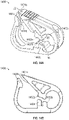
- FIGS 13A and 13B illustrate another embodiment of a pinch clamp 1300.
- Pinch clamp 1300 can include clamping surfaces 16 and 26 which can be configured in any of the various ways described above as well as a hinge 30.
- Hinge 30 can be structured to form an elliptical-shaped opening 1301 between hinge 30 and clamping surfaces 16 and 26.
- pinch clamp 1300 can include rounded outer edges which can enhance patient comfort.
- FIGS 14A and 14B illustrate another embodiment of a pinch clamp 1400 that includes various lateral disengagement prevention features.
- pinch clamp 1400 can include clamping surfaces 16 and 26. Additionally, to prevent lateral disengagement, clamping surface 26 can include recessed surfaces 1402a while clamping surface 16 can include lateral posts 1402b. As shown, lateral posts 1402b can be formed on opposing sides of clamping surface 16. Recessed surfaces 1402a can be sufficiently recessed to allow clamping surface 26 to insert between lateral posts 1402b. With clamping surface 26 inserted between lateral posts 1402b, lateral movement of clamping surface 26 with respect to clamping surface 16 will be prevented as recessed surfaces 1402a contact lateral posts 1402b. In some embodiments, including the depicted embodiment, lateral posts 1402b are offset.
- Pinch clamp 1400 may also include lateral disengagement prevention features formed at interface surface 22.
- interface surface 22 may be formed with outwardly facing recessed surfaces 1401a which can be positioned between inwardly facing lateral protrusions 1401b that are positioned on opposing sides of ledge 15. Accordingly, when interface surface 22 is secured under ledge 15, lateral protrusions 1401b will contact recessed surfaces 1401a to prevent lateral movement.
- pinch clamp 1400 is shown as including two types of lateral disengagement prevention features, in other embodiments, a pinch clamp may only include one of these features.
- a pinch clamp may include rounded outer edges. However, by rounding the outer edges, the width of interface surface 22 and ledge 15 may be reduced thereby increasing the likelihood that the pinch clamp may be laterally disengaged.
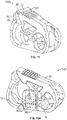
- interface surface 22 can be molded or otherwise formed to include ends 1501 that protrude beyond the outer surface of the remaining portions of second arm 20, as shown in Figure 15 . These protruding ends 1501 increase the width of interface surface 22 to thereby maximize the amount of lateral displacement that would be required to disengage the pinch clamp.
- the clamping surfaces may also be configured to include lateral disengagement prevention features similar to those described above with reference to Figures 14A and 14B .
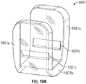
- FIG 16A illustrates another embodiment of a pinch clamp 1600 that employs a separate component 1601 to prevent lateral disengagement while Figure 16B shows component 1601 in isolation.
- pinch clamp 1600 can include a recessed section 1600a that is formed in first arm 12 and positioned generally below and to the side of clamping surface 16.
- Recessed section 1600a can be shaped and sized to accommodate lateral disengagement prevention component 1601 in a manner that causes the outer surfaces of lateral disengagement prevention component 1601 to substantially align with the outer surfaces of first arm 12. Therefore, even though a separate component is used, there will not be sharp edges or transitions between pinch clamp 1600 and component 1601.
- Component 1601 can have a U-shape that is formed by a bottom section 1601b and opposing arms 1601a that extend upwardly from opposite ends of bottom section 1601b.
- Each of arms 1601a can include an inward protrusion 1601c that is positioned such that the bottom ledge of each protrusion 1601c is located on top of first arm 12 when bottom section 1601b is secured within recessed section 1600a.
- Protrusions 1601c therefore function to prevent component 1601 from being separated from pinch clamp 1600.
- component 1601 may also be secured to arm 12 using an adhesive.
- Arms 1601a can have a sufficient length to ensure that they overlap second arm 20 or to at least overlap a portion of clamping surface 26 to thereby limit how far arm 20 can be laterally displaced relative to arm 12.
- the various lateral disengagement prevention features/components described herein also function to center the tubing within the pinch clamp to ensure proper clamping. Accordingly, embodiments of the present invention ensure that the tubing is properly clamped and will not unintentionally become disengaged.
- FIG 17 illustrates another embodiment of a pinch clamp 1700 in which clamping surfaces 16 and 26 are configured to provide positive fluid displacement.
- clamping surface 16 includes raised surfaces 1701a and 1701b which are spaced apart to form a recessed surface 1701c.
- Clamping surface 26 is similarly configured with raised surfaces 1702a and 1702b which are spaced apart to form a recessed surface 1702c.
- Raised surfaces 1702a and 1702b can be distally offset relative to raised surfaces 1701a and 1701b such that, when pinch clamp 1700 is engaged, raised surface 1702b will insert into recessed surface 1701c and raised surface 1701a will insert into recessed surface 1702c.
- raised surface 1702b can be vertically offset relative to recessed surface 1702c such that raised surface 1702b will insert into recessed surface 1701c prior to raised surface 1701a inserting into recessed surface 1702c.
- This vertical offset will cause tubing to first be clamped within recessed surface 1701c and then clamped within recessed surface 1702c.
- fluid contained within the portion of the tubing that is distal to raised surface 1702b (or with respect to the orientation shown in Figure 17 , to the left of raised surface 1702b) after raised surface 1702b is clamped will be forced distally (or towards the patient) when raised surface 1701a is subsequently clamped.
- Raised surfaces 1702a and 1701b increase the length of tubing that will be clamped. For example, as raised surface 1701a inserts into recessed surface 1702c, the tubing will be clamped along recessed surface 1702c and raised surface 1702a.
- Raised surface 1702a can also be vertically offset with respect to recessed surface 1702c so that raised surface 1702a clamps the tubing after raised surface 1701a thereby increasing the amount of positive fluid displacement. In Figure 17 , this vertical offset is accomplished by angling clamping surface 26 relative to clamping surface 16 so that the distance between the two surfaces increases from the proximal to the distal ends of the surfaces. However, the vertical offset could also be accomplished in other ways such as by angling clamping surface 16. This configuration of clamping surfaces 16 and 26 can be employed in conjunction with any of the above described lateral displacement features.
Landscapes
- Health & Medical Sciences (AREA)
- Heart & Thoracic Surgery (AREA)
- Life Sciences & Earth Sciences (AREA)
- Animal Behavior & Ethology (AREA)
- Public Health (AREA)
- Biomedical Technology (AREA)
- Hematology (AREA)
- Engineering & Computer Science (AREA)
- Veterinary Medicine (AREA)
- General Health & Medical Sciences (AREA)
- Anesthesiology (AREA)
- Pulmonology (AREA)
- Biophysics (AREA)
- Vascular Medicine (AREA)
- Infusion, Injection, And Reservoir Apparatuses (AREA)
- Clamps And Clips (AREA)
- Electrical Discharge Machining, Electrochemical Machining, And Combined Machining (AREA)
- Load-Engaging Elements For Cranes (AREA)
Applications Claiming Priority (5)
| Application Number | Priority Date | Filing Date | Title |
|---|---|---|---|
| US201562247615P | 2015-10-28 | 2015-10-28 | |
| US201662296372P | 2016-02-17 | 2016-02-17 | |
| US15/286,248 US11040186B2 (en) | 2015-10-28 | 2016-10-05 | Pinch clamp device |
| EP16785059.3A EP3368144B1 (de) | 2015-10-28 | 2016-10-06 | Quetschklemmenvorrichtung |
| PCT/US2016/055856 WO2017074681A1 (en) | 2015-10-28 | 2016-10-06 | Pinch clamp device |
Related Parent Applications (2)
| Application Number | Title | Priority Date | Filing Date |
|---|---|---|---|
| EP16785059.3A Division-Into EP3368144B1 (de) | 2015-10-28 | 2016-10-06 | Quetschklemmenvorrichtung |
| EP16785059.3A Division EP3368144B1 (de) | 2015-10-28 | 2016-10-06 | Quetschklemmenvorrichtung |
Publications (1)
| Publication Number | Publication Date |
|---|---|
| EP4062964A1 true EP4062964A1 (de) | 2022-09-28 |
Family
ID=57184847
Family Applications (2)
| Application Number | Title | Priority Date | Filing Date |
|---|---|---|---|
| EP16785059.3A Active EP3368144B1 (de) | 2015-10-28 | 2016-10-06 | Quetschklemmenvorrichtung |
| EP22173613.5A Pending EP4062964A1 (de) | 2015-10-28 | 2016-10-06 | Quetschklemmenvorrichtung |
Family Applications Before (1)
| Application Number | Title | Priority Date | Filing Date |
|---|---|---|---|
| EP16785059.3A Active EP3368144B1 (de) | 2015-10-28 | 2016-10-06 | Quetschklemmenvorrichtung |
Country Status (11)
| Country | Link |
|---|---|
| US (3) | US11040186B2 (de) |
| EP (2) | EP3368144B1 (de) |
| JP (3) | JP7058597B2 (de) |
| CN (4) | CN108348743A (de) |
| AU (3) | AU2016346886B2 (de) |
| CA (2) | CA3096795C (de) |
| ES (1) | ES2924404T3 (de) |
| MX (1) | MX2018004680A (de) |
| MY (1) | MY197214A (de) |
| SG (1) | SG11201803069PA (de) |
| WO (1) | WO2017074681A1 (de) |
Cited By (1)
| Publication number | Priority date | Publication date | Assignee | Title |
|---|---|---|---|---|
| US11724088B2 (en) | 2015-10-28 | 2023-08-15 | Becton, Dickinson And Company | Pinch clamp device |
Families Citing this family (22)
| Publication number | Priority date | Publication date | Assignee | Title |
|---|---|---|---|---|
| US10589082B2 (en) | 2016-02-17 | 2020-03-17 | Becton, Dickinson And Company | Pinch clamp |
| DE102017212883A1 (de) * | 2017-07-26 | 2019-01-31 | B. Braun Melsungen Ag | Schlauchklemme zum Abklemmen eines medizinischen Schlauches |
| DE102017122647A1 (de) * | 2017-09-28 | 2019-03-28 | B. Braun Melsungen Ag | Schlauchklemme und volumetrische Pumpe mit Schlauchklemme |
| CN111886044B (zh) * | 2018-03-21 | 2023-07-25 | 康尔福盛303公司 | 用于静脉注射流体施用的线性致动式流量控制器 |
| US11020581B2 (en) * | 2018-10-04 | 2021-06-01 | Becton, Dickinson And Company | Pinch clamp |
| JP7530159B2 (ja) * | 2018-11-05 | 2024-08-07 | ニプロ株式会社 | 医療用チューブクランプ |
| CN109529188A (zh) * | 2018-12-17 | 2019-03-29 | 陈琪 | 一种多功能止水夹 |
| US11571543B2 (en) | 2019-04-08 | 2023-02-07 | Becton, Dickinson And Company | Catheter system clamp, systems, and methods |
| US12083290B2 (en) * | 2019-04-08 | 2024-09-10 | Becton, Dickinson And Company | Catheter assembly clamp having an acoustic sensor |
| JP7480784B2 (ja) * | 2019-10-25 | 2024-05-10 | ニプロ株式会社 | 医療用チューブクランプ |
| CN115485012B (zh) * | 2020-05-11 | 2026-03-31 | 泰尔茂株式会社 | 夹紧件 |
| BR102020010672B1 (pt) * | 2020-05-27 | 2022-04-12 | Pfd - Comércio Varejista De Equipamentos Médicos Ltda | Kit de barreira para tubo endotraqueal com tampa vedante acoplado à clamp com diversos estágios para ajuste do grau de oclusão para uso em procedimentos de manejo avançado das vias aéreas |
| US11819661B2 (en) * | 2020-09-29 | 2023-11-21 | Carefusion 303, Inc. | Sliding flow controller |
| US11975169B2 (en) * | 2021-05-24 | 2024-05-07 | Fresenius Medical Care Holdings, Inc. | Symmetric tubing clamps |
| EP4366247A4 (de) * | 2021-07-01 | 2024-10-23 | LG Electronics Inc. | Signalverarbeitungsvorrichtung und kommunikationsvorrichtung für ein fahrzeug damit |
| US20230020041A1 (en) * | 2021-07-19 | 2023-01-19 | Carefusion 303, Inc. | Levered iv flow regulation clamp assembly |
| CN113599670B (zh) * | 2021-10-08 | 2021-12-03 | 江苏康亦徳医疗器械有限公司 | 一种便捷式医用管夹 |
| JP2025511828A (ja) * | 2022-04-05 | 2025-04-16 | アヴェント インコーポレイテッド | チューブ固定装置 |
| DE112023002217T5 (de) * | 2022-05-12 | 2025-03-13 | Abiomed, Inc. | Vorrichtung zur Kathetersicherung |
| USD987821S1 (en) * | 2022-11-29 | 2023-05-30 | McKay S. Crowder | Cannula release device |
| USD1069569S1 (en) * | 2023-03-04 | 2025-04-08 | Carolina Components Group, Inc. | Pinch clamp |
| USD1083088S1 (en) * | 2023-03-04 | 2025-07-08 | Carolina Components Group, Inc. | Pinch clamp |
Citations (6)
| Publication number | Priority date | Publication date | Assignee | Title |
|---|---|---|---|---|
| WO2004036102A2 (en) * | 2002-10-18 | 2004-04-29 | Twin Bay Medical, Inc. | Conduit clamp |
| US20060169934A1 (en) * | 2005-01-28 | 2006-08-03 | Twin Bay Medical, Inc. | Conduit clamp |
| EP2332611A1 (de) * | 2009-12-10 | 2011-06-15 | Fenwal, Inc. | Irreversibel schliessbare Durchflussregelungsklemme für flexible Schläuche |
| EP2711039A1 (de) * | 2011-05-16 | 2014-03-26 | Terumo Kabushiki Kaisha | Klemme und blutbeutelsystem |
| JP2016054810A (ja) * | 2014-09-05 | 2016-04-21 | フォルテ グロウ メディカル株式会社 | 医療用クランプ具 |
| WO2017142598A1 (en) * | 2016-02-17 | 2017-08-24 | Becton, Dickinson And Company | Pinch clamp |
Family Cites Families (119)
| Publication number | Priority date | Publication date | Assignee | Title |
|---|---|---|---|---|
| US3344966A (en) * | 1965-05-17 | 1967-10-03 | Central Specialties Co | Display hanger |
| US3419245A (en) * | 1965-11-29 | 1968-12-31 | Vargas Mfg Co | Tube clamp |
| US3350754A (en) * | 1966-03-25 | 1967-11-07 | Central Specialties Company | Flexible clothing clamp structure |
| US3698681A (en) | 1970-12-15 | 1972-10-17 | Illinois Tool Works | On-off clamp for i. v. systems |
| US3847370A (en) * | 1972-02-16 | 1974-11-12 | Horizon Ind Ltd | Tube servicing device |
| US3822052A (en) * | 1973-04-02 | 1974-07-02 | Illinois Tool Works | Shut off clamp |
| US3924307A (en) * | 1974-04-29 | 1975-12-09 | Raymond F Tate | Picture framing clip |
| JPS5252394A (en) | 1975-10-24 | 1977-04-27 | Hochiki Corp | Transmission type smoke detector |
| US4053135A (en) | 1976-09-20 | 1977-10-11 | Sigma Scientific Development, Inc. | Hose clamp |
| US4112944A (en) * | 1976-12-13 | 1978-09-12 | Williams Gayland M | Tube clamp and piercing device |
| US4097020A (en) * | 1977-05-05 | 1978-06-27 | Howard Sussman | Plant-watering device |
| US4115182A (en) * | 1977-06-29 | 1978-09-19 | Arenco Machine Company | Sealing means |
| US4235412A (en) * | 1978-10-30 | 1980-11-25 | Plastronics, Inc. | Tube clamping device |
| DE3039591A1 (de) * | 1980-10-21 | 1982-05-19 | Günter van Dr.med. 4000 Düsseldorf Endert | Adapter |
| US4346869A (en) | 1981-03-12 | 1982-08-31 | Macneill Robert L | Tube clamp |
| US4487205A (en) * | 1982-04-26 | 1984-12-11 | Ethicon, Inc. | Non-metallic, bio-compatible hemostatic clips |
| US4589626A (en) * | 1985-03-13 | 1986-05-20 | Bioresearch Inc. | Hose clamp |
| CH669117A5 (de) | 1985-06-24 | 1989-02-28 | Contempo Products | Geraet zum verschliessen und trennen eines schlauches, insbesondere eines bei einer dialyse oder einer infusion verwendeten schlauches. |
| FR2590645A1 (fr) | 1985-11-25 | 1987-05-29 | Diffusion Tech Fse | Appareil pince-tube manuel pour circuits d'aspiration ou de compression de fluides |
| US4726372A (en) * | 1986-09-19 | 1988-02-23 | Metatech Corporation | Hemostatic clip |
| IT1197832B (it) * | 1986-10-10 | 1988-12-06 | Walter Alessio | Collare per fissare tubi,cavi,tondini e simili |
| US4854766A (en) * | 1988-05-12 | 1989-08-08 | Gencorp Inc. | Slip bearing for a sway bar clamp |
| JPH024384A (ja) | 1988-06-14 | 1990-01-09 | Terumo Corp | クランプ |
| DE8812121U1 (de) | 1988-09-26 | 1989-01-05 | Süddeutsche Feinmechanik GmbH, 63607 Wächtersbach | Klemme |
| US4988355A (en) * | 1990-01-16 | 1991-01-29 | Leveen Eric G | Arterial clamp |
| US5035399A (en) * | 1990-05-25 | 1991-07-30 | C.R. Bard, Inc. | Protective tubing clamp apparatus |
| US5147336A (en) * | 1990-06-05 | 1992-09-15 | The Kendall Company | Adapter kit for a catheter introducer |
| US5395344A (en) * | 1990-06-08 | 1995-03-07 | Genetic Laboratories Wound Care, Inc. | Catheter anchoring device |
| JP3081235B2 (ja) | 1990-11-26 | 2000-08-28 | 株式会社ニッショー | クランプ |
| DE4118732A1 (de) | 1991-06-07 | 1992-12-10 | Joka Kathetertechnik Gmbh | Schlauchklemme fuer medizinische zwecke |
| US5336159A (en) * | 1992-08-25 | 1994-08-09 | Cheng Tzu Keng | Infrared massager |
| US5318546A (en) | 1992-08-28 | 1994-06-07 | Bierman Steven F | Method of catheter irrigation and aspiration |
| US5282832A (en) * | 1992-10-09 | 1994-02-01 | United States Surgical Corporation | Suture clip |
| WO1994015535A1 (en) * | 1993-01-07 | 1994-07-21 | Hayhurst, John, O. | Clip for suture |
| US5292312A (en) * | 1993-01-08 | 1994-03-08 | Struckmeyer Corporation | Universal tube lumen catheter holder |
| US5398679A (en) * | 1993-09-13 | 1995-03-21 | Freed; M. Simon | Hinged endotracheal tube holder having both a safety clamp and a securing clamp |
| US5429616A (en) * | 1994-05-31 | 1995-07-04 | Schaffer; David I. | Occludable catheter |
| IT235145Y1 (it) * | 1994-07-07 | 2000-03-31 | Cgm Spa | Pinzetta elastica per chiudere piccoli tubi flessibili |
| US5865813A (en) | 1995-07-14 | 1999-02-02 | Alaris Medical Systems, Inc. | Intravenous tube occluder |
| US6162201A (en) * | 1995-12-01 | 2000-12-19 | Cohen; Kenneth L. | Internal urinary catheter |
| WO1998016385A1 (de) * | 1996-10-11 | 1998-04-23 | Koenig & Bauer Ag | Festhaltevorrichtung für einen druckträger |
| US6095479A (en) * | 1997-03-19 | 2000-08-01 | Hangglider Partners | Adjustable mounting device |
| US5842932A (en) * | 1997-07-14 | 1998-12-01 | Goddard; Frederic W. | Sight for putter type golf club |
| US6089527A (en) | 1997-10-03 | 2000-07-18 | Medisystems Technology Corporation | Squeeze clamp for flexible tubing |
| US6279256B1 (en) * | 1997-12-02 | 2001-08-28 | Jonas Norolof | Label holder |
| US5989174A (en) * | 1998-04-02 | 1999-11-23 | Neolt S.P.A. | Automatic machine for folding long sheets, particularly technical drawings |
| JP4335983B2 (ja) | 1998-09-17 | 2009-09-30 | 小林製薬株式会社 | チューブクリップ |
| DE69826475T2 (de) * | 1998-10-22 | 2005-02-24 | Industrie Borla S.P.A., Moncalieri | Klemmschelle für Schläuche für Infusionszwecke , Transfusionszwecke und dergleichen medizinische Vorrichtungen |
| USD431650S (en) * | 1998-10-22 | 2000-10-03 | Industrie Borla S.P.A. | Clamp for closing flexible hoses of infusion, transfusion medical equipment |
| IL127029A (en) * | 1998-11-12 | 2002-03-10 | Medivice Systems Ltd | Pinched grip |
| USD427307S (en) * | 1999-01-08 | 2000-06-27 | Industrie Borla S.P.A. | Clamp for flexible medical hoses |
| US6572588B1 (en) * | 2000-03-10 | 2003-06-03 | Venetec International, Inc. | Medical anchoring system |
| JP2001259030A (ja) | 2000-03-23 | 2001-09-25 | Kawasumi Lab Inc | クランプ及び医療用具 |
| US6349727B1 (en) * | 2000-05-25 | 2002-02-26 | Pos-T-Vac, Inc. | Penile clamp for inhibiting incontinence |
| AU2002225925A1 (en) * | 2000-10-26 | 2002-05-06 | Alpha Security Products, Inc. | Eas tag holder |
| USD465843S1 (en) | 2001-02-02 | 2002-11-19 | Industrie Borla S.P.A. | Clamp for flexible medical lines |
| US20020161333A1 (en) * | 2001-04-27 | 2002-10-31 | Luther Ronald B. | Catheter shut-off valve |
| US6638282B2 (en) * | 2001-10-16 | 2003-10-28 | Cetus, Lc | Umbilical cord cutting and clamping device |
| DE60334067D1 (de) * | 2002-01-31 | 2010-10-21 | Fenwal Inc | Irreversibel schliessbare stromregelklemme |
| US8262639B2 (en) | 2002-01-31 | 2012-09-11 | Fenwal, Inc. | Irreversible flow control clamp |
| JP2003245349A (ja) | 2002-02-26 | 2003-09-02 | Kawasumi Lab Inc | クランプ及び医療用具 |
| US7428771B2 (en) | 2002-10-23 | 2008-09-30 | Jms Co., Ltd. | Clip for dividing two liquids |
| WO2004041343A1 (en) * | 2002-11-04 | 2004-05-21 | Lynn Lawrence A D O | Catheter flushing fluid lock system and method |
| US6942647B2 (en) * | 2002-11-12 | 2005-09-13 | William M. Nickels | Pinch clamp cover |
| WO2005048854A2 (en) * | 2003-11-14 | 2005-06-02 | Alan Kessler | Safety surgical forceps |
| US7137611B2 (en) * | 2004-10-05 | 2006-11-21 | Ames Rubber Corporation | Pinch clamp for flexible tubing |
| US7234677B2 (en) | 2004-10-18 | 2007-06-26 | Z-Man Corporation | Pinch clamp |
| JP4754917B2 (ja) | 2004-10-19 | 2011-08-24 | テルモ株式会社 | 輸液装置 |
| DE102005004863A1 (de) | 2005-02-02 | 2006-08-03 | Fresenius Medical Care Deutschland Gmbh | Schlauchklemme |
| US7258695B2 (en) * | 2005-02-08 | 2007-08-21 | Sonetics International | Hair restoration device and methods of using and manufacturing the same |
| US7350761B1 (en) | 2005-07-13 | 2008-04-01 | Stuart John J | Soft hose pedal valve |
| US7300172B1 (en) * | 2005-09-06 | 2007-11-27 | Jo Ann Lefler | Illuminable attachment for vacuum wand |
| US7879013B2 (en) * | 2005-12-21 | 2011-02-01 | Venetec International, Inc. | Intravenous catheter anchoring device |
| CA2643595C (en) * | 2006-04-05 | 2015-03-24 | Noble House Group Pty. Ltd. | Non-reopening locking pinch clamp for tubing |
| GB0609079D0 (en) * | 2006-05-08 | 2006-06-21 | Bhp Billiton Petroleum Pty Ltd | Improvements relating to hose |
| US7686279B2 (en) | 2006-05-12 | 2010-03-30 | Caridianbct, Inc. | Non-reopenable clamp for tubing sets |
| US7856745B2 (en) * | 2006-08-24 | 2010-12-28 | Medical Components Inc. | Information clip for flexible tubing |
| US8025645B2 (en) * | 2007-05-25 | 2011-09-27 | Medical Components, Inc. | Guard for flexible tubing clamp and method of using same |
| FR2920513B1 (fr) * | 2007-09-04 | 2021-05-28 | Fresenius Vial | Pince de serrage pour tubulure souple, pompe munie de moyens pour ouvrir une telle pince et set de perfusion muni d'une telle pince. |
| US20090224131A1 (en) * | 2008-03-07 | 2009-09-10 | Product Harmonics, Llc | Broom stabilizer damper |
| US9017296B2 (en) * | 2008-04-01 | 2015-04-28 | Zevex, Inc. | Safety occluder and method of use |
| US7508316B1 (en) * | 2008-05-28 | 2009-03-24 | Raed Basheer Jamil Arrar | Portable interactive islamic prayer counter |
| WO2010062637A1 (en) | 2008-10-28 | 2010-06-03 | Medical Components, Inc. | Clamp for flexible tubing |
| US9774875B2 (en) | 2009-03-10 | 2017-09-26 | Avago Technologies General Ip (Singapore) Pte. Ltd. | Lossless and near-lossless image compression |
| ES2442876T3 (es) * | 2009-03-23 | 2014-02-14 | Gambro Lundia Ab | Pinza para cerrar tubos flexibles pertenecientes a equipos médicos |
| US8167259B2 (en) | 2009-04-06 | 2012-05-01 | Baxter International Inc. | Rapid attach and release clamps |
| CN101569768A (zh) * | 2009-05-22 | 2009-11-04 | 张亚平 | 一种蜗杆式输液调节器 |
| WO2011035367A1 (en) | 2009-09-23 | 2011-03-31 | Sukhvinder Singh | A pinch clamp |
| US9808572B2 (en) * | 2010-01-22 | 2017-11-07 | Deka Products Limited Partnership | System, method and apparatus for clamping |
| US9488200B2 (en) * | 2010-01-22 | 2016-11-08 | Deka Products Limited Partnership | System, method, and apparatus for clamping |
| US20120004624A1 (en) * | 2010-06-30 | 2012-01-05 | Carefusion 303, Inc. | Enhanced anti-flow protection for an intravenous set |
| CN102971021B (zh) | 2010-06-30 | 2016-10-12 | 泰尔茂株式会社 | 夹子及血液袋系统 |
| USD660198S1 (en) * | 2010-07-08 | 2012-05-22 | Seiko Epson Corporation | Clip for a wristband |
| US10335157B2 (en) * | 2010-10-02 | 2019-07-02 | Covidien Lp | Asymmetrical surgical clip with penetrating lock, non-slip clamping surface, severable hinge, hinge boss and pivoting applicator tip |
| US9079008B2 (en) | 2011-02-17 | 2015-07-14 | Nipro Corporation | Medical tube clamp |
| US20120316539A1 (en) * | 2011-06-13 | 2012-12-13 | Cuauhtemoc Villasana | Catheter Clamp |
| US8801677B2 (en) | 2011-09-14 | 2014-08-12 | Brandon Wallin | Medical clamp for flexible tubing |
| US9393008B2 (en) * | 2011-09-22 | 2016-07-19 | Cook Medical Technologies Llc | Suture clamp |
| US9050447B2 (en) | 2011-11-23 | 2015-06-09 | Carefusion 303, Inc. | Positive bolus clamp |
| US10082241B2 (en) * | 2011-12-21 | 2018-09-25 | Deka Products Limited Partnership | System, method, and apparatus for clamping |
| EP2813741B1 (de) * | 2012-02-07 | 2017-11-08 | Togo Seisakusyo Corporation | Schlauchklemme und verfahren zu deren herstellung |
| JP5989554B2 (ja) | 2012-02-07 | 2016-09-07 | 川澄化学工業株式会社 | クランプ及び医療用具 |
| US8702681B2 (en) * | 2012-05-31 | 2014-04-22 | Progeny Concepts, Llc | Catheter valve and methods of using same |
| US20140039675A1 (en) * | 2012-08-03 | 2014-02-06 | Nimer Mohammed Ead | Instructional humanoid robot apparatus and a method thereof |
| US9518667B2 (en) * | 2012-08-30 | 2016-12-13 | C. R. Bard, Inc. | Tubing clamp |
| US9833606B2 (en) | 2012-09-07 | 2017-12-05 | Fenwal, Inc. | Non-reopenable flow control clamp |
| US8905978B2 (en) | 2013-03-14 | 2014-12-09 | Haemonetics Corporation | Non-reopening tubing clamp and method of use thereof |
| US20140171986A1 (en) * | 2013-09-13 | 2014-06-19 | Ethicon Endo-Surgery, Inc. | Surgical Clip Having Comliant Portion |
| US9664213B2 (en) * | 2014-08-21 | 2017-05-30 | Cook Medical Technologies Llc | System for containment and organization of medical wire |
| US10173018B1 (en) | 2014-09-02 | 2019-01-08 | Hal Rucker | Tamper resistant clamp |
| WO2016081323A1 (en) * | 2014-11-21 | 2016-05-26 | Otimo Medical, Llc | Devices and methods for drainage, infusion, or instillation of fluids |
| US20170007257A1 (en) * | 2015-07-09 | 2017-01-12 | Uwm Research Foundation, Inc. | Umbilical cord clamp |
| US20160355205A1 (en) * | 2015-07-20 | 2016-12-08 | Cheryl Glynn Upton | Device Holding Clip for Shopping Cart |
| GB2541221B (en) * | 2015-08-12 | 2021-04-14 | Royal United Hospitals Bath Nhs Found Trust | Pinch valve for a urinary drainage system |
| US20170082207A1 (en) | 2015-09-22 | 2017-03-23 | Daniel M. Tran | Adjustable Reusable Flow Regulator |
| US11040186B2 (en) | 2015-10-28 | 2021-06-22 | Becton, Dickinson And Company | Pinch clamp device |
| DE102017103079A1 (de) * | 2017-02-15 | 2018-08-16 | Norma Germany Gmbh | Schelle |
| US10932788B2 (en) * | 2018-04-11 | 2021-03-02 | Covidien Lp | Ligation clip with latching and retention features |
| US12376864B2 (en) * | 2020-03-24 | 2025-08-05 | Jichi Medical University | Medical instrument suitable for ligature or similar |
-
2016
- 2016-10-05 US US15/286,248 patent/US11040186B2/en active Active
- 2016-10-06 MY MYPI2018000577A patent/MY197214A/en unknown
- 2016-10-06 EP EP16785059.3A patent/EP3368144B1/de active Active
- 2016-10-06 CA CA3096795A patent/CA3096795C/en active Active
- 2016-10-06 EP EP22173613.5A patent/EP4062964A1/de active Pending
- 2016-10-06 ES ES16785059T patent/ES2924404T3/es active Active
- 2016-10-06 WO PCT/US2016/055856 patent/WO2017074681A1/en not_active Ceased
- 2016-10-06 CN CN201680063492.6A patent/CN108348743A/zh active Pending
- 2016-10-06 JP JP2018522530A patent/JP7058597B2/ja active Active
- 2016-10-06 CA CA3002659A patent/CA3002659C/en active Active
- 2016-10-06 MX MX2018004680A patent/MX2018004680A/es unknown
- 2016-10-06 SG SG11201803069PA patent/SG11201803069PA/en unknown
- 2016-10-06 AU AU2016346886A patent/AU2016346886B2/en active Active
- 2016-10-28 CN CN202110210765.8A patent/CN112999493B/zh active Active
- 2016-10-28 CN CN201621182975.1U patent/CN206852893U/zh active Active
- 2016-10-28 CN CN201610958219.1A patent/CN106620993B/zh active Active
-
2020
- 2020-01-29 AU AU2020200598A patent/AU2020200598B2/en active Active
-
2021
- 2021-05-12 US US17/318,799 patent/US11724088B2/en active Active
- 2021-11-02 JP JP2021179523A patent/JP7216173B2/ja active Active
-
2022
- 2022-02-24 AU AU2022201267A patent/AU2022201267B2/en active Active
-
2023
- 2023-01-19 JP JP2023006565A patent/JP7649806B2/ja active Active
- 2023-06-28 US US18/215,602 patent/US20230338725A1/en active Pending
Patent Citations (6)
| Publication number | Priority date | Publication date | Assignee | Title |
|---|---|---|---|---|
| WO2004036102A2 (en) * | 2002-10-18 | 2004-04-29 | Twin Bay Medical, Inc. | Conduit clamp |
| US20060169934A1 (en) * | 2005-01-28 | 2006-08-03 | Twin Bay Medical, Inc. | Conduit clamp |
| EP2332611A1 (de) * | 2009-12-10 | 2011-06-15 | Fenwal, Inc. | Irreversibel schliessbare Durchflussregelungsklemme für flexible Schläuche |
| EP2711039A1 (de) * | 2011-05-16 | 2014-03-26 | Terumo Kabushiki Kaisha | Klemme und blutbeutelsystem |
| JP2016054810A (ja) * | 2014-09-05 | 2016-04-21 | フォルテ グロウ メディカル株式会社 | 医療用クランプ具 |
| WO2017142598A1 (en) * | 2016-02-17 | 2017-08-24 | Becton, Dickinson And Company | Pinch clamp |
Cited By (1)
| Publication number | Priority date | Publication date | Assignee | Title |
|---|---|---|---|---|
| US11724088B2 (en) | 2015-10-28 | 2023-08-15 | Becton, Dickinson And Company | Pinch clamp device |
Also Published As
Similar Documents
| Publication | Publication Date | Title |
|---|---|---|
| AU2022201267B2 (en) | Pinch clamp device | |
| US11628290B2 (en) | Pinch clamp | |
| US20100274268A1 (en) | Squeeze-to-set medical clamp | |
| EP3308823A1 (de) | Kathetereinführhilfe | |
| CN106618667B (zh) | 弹簧夹 |
Legal Events
| Date | Code | Title | Description |
|---|---|---|---|
| PUAI | Public reference made under article 153(3) epc to a published international application that has entered the european phase |
Free format text: ORIGINAL CODE: 0009012 |
|
| STAA | Information on the status of an ep patent application or granted ep patent |
Free format text: STATUS: THE APPLICATION HAS BEEN PUBLISHED |
|
| AC | Divisional application: reference to earlier application |
Ref document number: 3368144 Country of ref document: EP Kind code of ref document: P |
|
| AK | Designated contracting states |
Kind code of ref document: A1 Designated state(s): AL AT BE BG CH CY CZ DE DK EE ES FI FR GB GR HR HU IE IS IT LI LT LU LV MC MK MT NL NO PL PT RO RS SE SI SK SM TR |
|
| STAA | Information on the status of an ep patent application or granted ep patent |
Free format text: STATUS: REQUEST FOR EXAMINATION WAS MADE |
|
| 17P | Request for examination filed |
Effective date: 20230322 |
|
| RBV | Designated contracting states (corrected) |
Designated state(s): AL AT BE BG CH CY CZ DE DK EE ES FI FR GB GR HR HU IE IS IT LI LT LU LV MC MK MT NL NO PL PT RO RS SE SI SK SM TR |
|
| STAA | Information on the status of an ep patent application or granted ep patent |
Free format text: STATUS: EXAMINATION IS IN PROGRESS |
|
| 17Q | First examination report despatched |
Effective date: 20240821 |