EP4062994B9 - Verfahren zur montage einer filterzelle für eine raumlufttechnische anlage - Google Patents
Verfahren zur montage einer filterzelle für eine raumlufttechnische anlage Download PDFInfo
- Publication number
- EP4062994B9 EP4062994B9 EP21164518.9A EP21164518A EP4062994B9 EP 4062994 B9 EP4062994 B9 EP 4062994B9 EP 21164518 A EP21164518 A EP 21164518A EP 4062994 B9 EP4062994 B9 EP 4062994B9
- Authority
- EP
- European Patent Office
- Prior art keywords
- housing
- passage surface
- filter plate
- contact
- edges
- Prior art date
- Legal status (The legal status is an assumption and is not a legal conclusion. Google has not performed a legal analysis and makes no representation as to the accuracy of the status listed.)
- Active
Links
Images





Classifications
-
- B—PERFORMING OPERATIONS; TRANSPORTING
- B01—PHYSICAL OR CHEMICAL PROCESSES OR APPARATUS IN GENERAL
- B01D—SEPARATION
- B01D46/00—Filters or filtering processes specially modified for separating dispersed particles from gases or vapours
- B01D46/0001—Making filtering elements
-
- B—PERFORMING OPERATIONS; TRANSPORTING
- B01—PHYSICAL OR CHEMICAL PROCESSES OR APPARATUS IN GENERAL
- B01D—SEPARATION
- B01D46/00—Filters or filtering processes specially modified for separating dispersed particles from gases or vapours
- B01D46/0002—Casings; Housings; Frame constructions
- B01D46/0016—Folded frame or housing constructions
-
- B—PERFORMING OPERATIONS; TRANSPORTING
- B01—PHYSICAL OR CHEMICAL PROCESSES OR APPARATUS IN GENERAL
- B01D—SEPARATION
- B01D46/00—Filters or filtering processes specially modified for separating dispersed particles from gases or vapours
- B01D46/10—Particle separators, e.g. dust precipitators, using filter plates, sheets or pads having plane surfaces
- B01D46/12—Particle separators, e.g. dust precipitators, using filter plates, sheets or pads having plane surfaces in multiple arrangements
- B01D46/121—V-type arrangements
-
- F—MECHANICAL ENGINEERING; LIGHTING; HEATING; WEAPONS; BLASTING
- F24—HEATING; RANGES; VENTILATING
- F24F—AIR-CONDITIONING; AIR-HUMIDIFICATION; VENTILATION; USE OF AIR CURRENTS FOR SCREENING
- F24F13/00—Details common to, or for air-conditioning, air-humidification, ventilation or use of air currents for screening
- F24F13/28—Arrangement or mounting of filters
-
- F—MECHANICAL ENGINEERING; LIGHTING; HEATING; WEAPONS; BLASTING
- F24—HEATING; RANGES; VENTILATING
- F24F—AIR-CONDITIONING; AIR-HUMIDIFICATION; VENTILATION; USE OF AIR CURRENTS FOR SCREENING
- F24F8/00—Treatment, e.g. purification, of air supplied to human living or working spaces otherwise than by heating, cooling, humidifying or drying
- F24F8/10—Treatment, e.g. purification, of air supplied to human living or working spaces otherwise than by heating, cooling, humidifying or drying by separation, e.g. by filtering
- F24F8/108—Treatment, e.g. purification, of air supplied to human living or working spaces otherwise than by heating, cooling, humidifying or drying by separation, e.g. by filtering using dry filter elements
-
- B—PERFORMING OPERATIONS; TRANSPORTING
- B01—PHYSICAL OR CHEMICAL PROCESSES OR APPARATUS IN GENERAL
- B01D—SEPARATION
- B01D2265/00—Casings, housings or mounting for filters specially adapted for separating dispersed particles from gases or vapours
- B01D2265/04—Permanent measures for connecting different parts of the filter, e.g. welding, glueing or moulding
-
- B—PERFORMING OPERATIONS; TRANSPORTING
- B01—PHYSICAL OR CHEMICAL PROCESSES OR APPARATUS IN GENERAL
- B01D—SEPARATION
- B01D2277/00—Filters specially adapted for separating dispersed particles from gases or vapours characterised by the position of the filter in relation to the gas stream
- B01D2277/20—Inclined, i.e. forming an angle of between 0° and 90°
-
- B—PERFORMING OPERATIONS; TRANSPORTING
- B01—PHYSICAL OR CHEMICAL PROCESSES OR APPARATUS IN GENERAL
- B01D—SEPARATION
- B01D2279/00—Filters adapted for separating dispersed particles from gases or vapours specially modified for specific uses
- B01D2279/65—Filters adapted for separating dispersed particles from gases or vapours specially modified for specific uses for the sterilisation of air
Definitions
- the invention relates to a method for assembling a filter cell for a ventilation system for the separation of fine dust and/or suspended matter, such as aerosols, toxic dust, viruses and/or bacteria, from the supply and exhaust air, wherein the filter cell a box-shaped housing and at least one rectangular filter plate arranged in the housing, the housing having six housing surfaces, with two housing surfaces as passage surfaces, namely as an inlet surface with at least one, preferably rectangular, inlet opening and as an outlet surface with at least one, preferably rectangular, outlet opening, are designed and the four remaining housing surfaces are designed as closed side surfaces connecting the two passage surfaces and form a flow channel with a rectangular cross section running from the inlet surface to the outlet surface, this filter plate having two parallel aligned longitudinal edges and two parallel to the inlet opening and to the corresponding outlet opening has parallel side edges, one longitudinal edge of this filter plate resting sealingly on the inside of one passage surface, the other longitudinal edge of this filter plate resting sealingly on the inside of the other passage surface and the two side edges of this filter plate resting sealingly
- Such filter cells are suitable for large volume flows and are characterized by long filter service lives.
- Known filter cells have a housing that is constructed from six separately formed housing surfaces that form the six side surfaces of the housing. Two of these six housing surfaces are designed as passage surfaces, which either have at least one inlet opening or at least one outlet opening. If a passage area has more than one inlet opening or more than one outlet opening, the respective area between two adjacent inlet or outlet openings is designed as a separate web. The six side surfaces and any webs are riveted together and then sealed with the filter plates using a liquid PU adhesive. This manufacturing process is very complex due to the high number of individual components that have to be assembled. The production times are also long because of the long drying times.
- the object of the invention is to avoid the aforementioned disadvantages and to provide a method by means of which a filter cell can be produced more easily and quickly.
- a passage surface is formed in one piece with the two side surfaces adjacent to opposite edges, which in the assembled state are in contact with a side edge of each filter plate, and that in relation to the remaining three housing surfaces, the other passage surface as well as the two other side surfaces are each formed separately or in one piece with at least one of the remaining housing surfaces and that all open housing edges are glued and thus sealed.
- the six housing surfaces are each aligned at a right angle to one another.
- the filter cell is sealed from the environment in the area of all edges by gluing.
- each of the two passage surfaces is fixed in the contact area with an adjacent, separately formed side surface and, on the other hand, each side surface formed in one piece with a passage surface is fixed in the contact area with an adjacent, separately formed side surface.
- all open edge areas are closed by gluing.
- the method according to the invention allows the assembly time and the throughput time to be significantly reduced.
- the method according to the invention allows a filter cell to be manufactured much more quickly.
- the housing can, for example, be made from only four parts, for example four sheet metal parts, and the corresponding number of desired filter plates.
- the construction of the filter cell itself can also be simplified. No rivets or screws are required. Welding is also not necessary.
- the overall weight can be reduced while at the same time using less adhesive. This leads to a reduction in manufacturing costs.
- the adhesive used serves both to seal the housing and to fix the housing surfaces, i.e. H. The adhesive ensures the tightness and stabilization of the housing.
- the filter cell produced using the method according to the invention can, for example, be used as a mini pleat filter cell for the separation of fine dust and suspended matter such as. B. aerosols, toxic dusts, viruses, bacteria from the supply and exhaust air in ventilation systems with large volume flows and long filter life.
- the filter cell can also be used for fine dust filtering as a pre- or final filter in air conditioning systems to separate fine dust.
- the filter cells are also suitable as a suspended matter filter in the form of a main filter or a final filter if high requirements for air purity and freedom from germs are to be achieved, for example in industry, research, medicine, pharmacy or nuclear technology.
- the housing consists of four parts, namely the passage surface with the two side surfaces formed in one piece with this passage surface and the other passage surface and the two separately formed side surfaces.
- the assembled housing can be clamped into a frame, preferably until the adhesive has hardened.
- the frame ensures optimal alignment of the housing surfaces glued together and prevents the housing surfaces glued together and, as a result, the filter plates inside the housing from changing in position as long as the glue has not yet dried sufficiently.
- the two side surfaces adjacent to opposite edges which in the assembled state are in contact with a side edge of each filter plate, can be formed in one piece by the relevant Inlet or outlet opening(s) a contact element with at least one contact surface is guided, the number of contact surfaces corresponding to the number of filter plates to be placed.
- the contact surfaces belonging to an inlet or outlet opening can be aligned obliquely towards one another and thus have a roof-like design.
- Both the two opposite edges of the passage surface and the opposite edges of the two side surfaces, which are formed in one piece with this passage surface, can each have a fold, the folds facing in the assembled state of the housing in the direction of the housing surface enclosing these folds on three sides are.
- the folds preferably have a maximum height of around 20 mm. These folds are sufficient to ensure a sufficient contact surface, which can be provided with adhesive, for example, to the adjacent housing surface and thus sufficient fixation after application of adhesive. On the other hand, a fold of this size also allows it to be inserted into a CNC adhesive application machine.
- the distance between the opposite folds of the passage surface can be larger, preferably four times the material thickness of the fold, than the distance between the opposite folds of each side surface.
- the two opposite edges which are in contact with another side surface in the assembled state, each have a fold, with each of the two folds in the assembled state of the housing resting on the outside of the respectively adjacent side surface.
- the distance between the folds of two opposite edges is slightly larger than the width of the housing.
- the folds preferably have a maximum height of around 20 mm.
- At least two opposite edges, preferably all four edges, of the other passage surface each have a fold, the other passage surface being attached in such a way that each of the two, preferably four, Folds in the assembled state of the housing rest on the outside of the adjacent side surface.
- the distance between the folds in the area of two opposite edges is slightly larger than the width of the housing.
- the folds preferably have a maximum height of around 20 mm.
- the passage surface and the two side surfaces formed in one piece with this passage surface and/or the other passage surface and/or the other two side surfaces can be made of sheet metal.
- the adhesive may include polyurethane.
- the adhesive is designed as a PU adhesive.
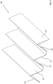
- filter plates can be arranged in a zigzag shape in the housing in such a way that two adjacent filter plates each touch each other on a longitudinal edge and the touching longitudinal edges are in contact in the area of the inside of the adjacent passage surface, which is arranged between two adjacent inlet openings or between two adjacent outlet openings is.
- the angle of attack is the same for all filter plates.
- the arrangement of the filter plates in the housing is also entirely possible for the arrangement of the filter plates in the housing to be designed in the manner of saw teeth of a saw blade, with two adjacent filter plates touching each other on one of their two longitudinal edges and the two touching longitudinal edges in the area with the inside of the adjacent passage surface are in contact, which is arranged between two adjacent inlet openings or between two adjacent outlet openings.
- the angle of attack of the first, third, fifth, etc. filter plates is unequal to the angle of attack of the second, fourth, etc. filter plates.
- a plurality of inlet openings arranged parallel to one another can be provided in one passage surface, and/or a plurality of outlet openings arranged parallel to one another can be provided in the other passage surface.
- the entrance openings and the outlet openings can be arranged offset from one another as viewed in the general direction of flow. In such a configuration, the number of inlet openings is usually one opening larger than the number of outlet openings.
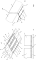
- Fig. 1a shows a flat circuit board that was produced, for example, by punching.
- the board includes a passage surface 1, which is formed in one piece with two side surfaces 2. When assembled, these two side surfaces 2 are in contact with a side edge 3 of each filter plate 4.
- a notch 5 can, for example, have been made in the area of the respective bending line.
- three openings which can be, for example, inlet openings 6, are provided, which are rectangular.
- the two opposite edges of the passage surface 1 and also the opposite edges of the two side surfaces 2, which are formed in one piece with this passage surface 1, each have a fold 7, the height of which is preferably not greater than 20 mm.
- the folds 7 face towards the housing surface which is surrounded by these folds 7 on three sides.
- the distance between the two opposite folds 7 of the passage surface 1 is greater than the distance between the two opposite folds 7 of each side surface 2.
- the distance is preferably four times the material thickness of a fold 7 larger.
- Fig. 1a shows, is on the inside of the passage surface 1 in the areas which, in the assembled state, are in contact with one of the two longitudinal edges 8 of the filter plate 4, and on the inside of each of the two side surfaces 2 in the areas which, in the assembled state, are in contact with one of the Both side edges 3 of each filter plate 4 are in contact, adhesive 9 is applied.
- the filter plates 4 are placed on the areas of the passage surface 1 provided with adhesive 9. This is in Fig. 2 recognizable.
- the filter plates 4 are placed in such a way that a zigzag shape results. This means that two filter plates 4, which are located on opposite sides of an inlet opening 6, touch one another on a longitudinal edge 8.
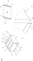
- the folds 7 of the passage surface 1 protrude on the outside after being bent compared to the folds 7 of the side surface 2. This leaves a gap 10 in the bent state between the fold 7 of the passage surface 1 and the fold 7 of the side surface 2.
- the width of the gap 10 corresponds at least to the material thickness of a separately formed side surface 11 that is now to be attached.
- the side surfaces 2 can be slightly out of position before the filter plates 4 are put on Fig. 1a have been bent up in the orientation shown. After the filter plates 4 have been placed, the remaining displacement takes place until the side surfaces 2 are in contact with the adjacent side edge 3 of each filter plate 4.
- the two open side housing surfaces are each closed with a side surface 11.
- Each of the two side surfaces 11 is attached so that each side surface 11 is inserted into the gap 10 on both sides.
- This condition is in Fig. 4a and b shown.
- the height of a fold 12 is preferably not greater than 20 mm.
- the folds 12 of the separately formed side surfaces 11 rest on the outside of the adjacent side surface 2 after the respective side surface 11 has been inserted.
- the housing surface that is still open at the top is closed with another passage surface 13, the four sides of which each have a fold 14. Rectangular outlet openings 18 are provided in the passage area 13.
- adhesive 9 is applied in the areas of the inside of the passage surface 13, which are in contact with the longitudinal edges 8 of the filter plates 4 in the assembled state. Adhesive 9 is also applied at least there in the edge region of the inside of the passage surface 13, which is in contact with the side surfaces 2, 11 after the passage surface 13 has been placed.
- each of the four folds 14 of the other passage surface 13 rests on the outside of the respective adjacent side surfaces 2, 11.
- the longitudinal edges of the inlet openings 6 and the longitudinal edges of the outlet openings 18 have the same orientation as the longitudinal edges 8 of each filter plate 4.
- the filter cell can be clamped into a frame 15.
- the frame 15 consists of four parts that are connected to one another in an articulated manner.
- the applied state is shown, ie the two ends have been screwed together so that the frame 15 is now closed.
- the filter cell is clamped in the frame 15 and can no longer move.
- the frame 15 can be opened and the finished filter cell can be removed.
- a contact element 16 which serves to hold the attached filter plates 4 during assembly.
- the contact element 16 has three roof-like areas, each area having two contact surfaces 17.
- the contact element 16 is inserted with its three roof-like areas into the three inlet openings 6 from below. The insertion preferably takes place before the adhesive 9 is applied to the circuit board Fig. 1 .
- the three protrude like a roof trained areas at the top out of the inlet openings 6 and the filter plates 4 can be placed on the areas of the passage surface 1 provided with the adhesive 9.
- the inclination of the two contact surfaces 17 of a roof-like area corresponds to the desired inclination of a filter plate 4.
- the three roof-like areas of the contact element 16 are later pulled out of the assembled filter cell.
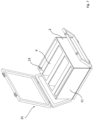
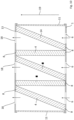
- Fig. 10 shows a filter cell according to the invention.
- the filter cell has a box-shaped housing and five rectangular filter plates 4 arranged in the housing.
- the housing has six housing surfaces, with two housing surfaces being designed as passage surfaces 1, 13, namely as an inlet surface with three rectangular inlet openings 6 and as an outlet surface with three rectangular outlet openings 18.
- the four remaining housing surfaces are designed as closed side surfaces connecting the two passage surfaces 1, 13 and form a flow channel with a rectangular cross section running from the inlet surface to the outlet surface.
- Each filter plate 4 has two longitudinal edges 8 and two parallel side edges 3 which are aligned parallel and parallel to the inlet openings 6 and to the outlet openings 18, one longitudinal edge 8 of each filter plate 4 resting sealingly on the inside of one passage surface 1, the other longitudinal edge 8 each filter plate 4 rests sealingly on the inside of the other passage surface 13 and the two side edges 3 of each filter plate 4 rest sealingly on the inside of one side surface.
- each filter plate 4 is selected in relation to the inlet openings 6 and the outlet openings 18 so that the air flowing into the housing through the inlet openings 6 and flowing out of the housing through the outlet openings 18 flows through a filter plate 4.
- Both passage surfaces 1, 13 have the same number of openings, namely three inlet openings 3 and three outlet openings 18, respectively.
- Each inlet opening 6 in one passage surface 1 is arranged congruently with the respective outlet opening 18 in the other passage surface 13.
- the inlet openings 6 and the corresponding outlet openings 18 are thus arranged in alignment when viewed in the general flow direction 19.
- the filter plates 4 have a course in the manner of saw teeth of a saw blade. Seen from left to right, in the exemplary embodiment shown, the first, third and fifth filter plates 4 are aligned obliquely, while the second and fourth filter plates 4 are aligned vertically. The angle of attack of the first, third and fifth filter plates 4 is therefore different from the angle of attack of the second and fourth filter plates 4.
Landscapes
- Chemical & Material Sciences (AREA)
- Engineering & Computer Science (AREA)
- Chemical Kinetics & Catalysis (AREA)
- Combustion & Propulsion (AREA)
- Mechanical Engineering (AREA)
- General Engineering & Computer Science (AREA)
- Filtering Of Dispersed Particles In Gases (AREA)
Priority Applications (6)
| Application Number | Priority Date | Filing Date | Title |
|---|---|---|---|
| PL21164518.9T PL4062994T3 (pl) | 2021-03-24 | 2021-03-24 | Sposób montażu komórki filtracyjnej dla instalacji wentylacyjnej do pomieszczenia |
| ES21164518T ES2970514T3 (es) | 2021-03-24 | 2021-03-24 | Procedimiento para el montaje de una célula filtrante para un sistema de aire acondicionado |
| HRP20240113TT HRP20240113T1 (hr) | 2021-03-24 | 2021-03-24 | Metoda postavljanja filtarske ćelije za sobni uređaj zraka |
| EP21164518.9A EP4062994B9 (de) | 2021-03-24 | 2021-03-24 | Verfahren zur montage einer filterzelle für eine raumlufttechnische anlage |
| RS20240157A RS65249B1 (sr) | 2021-03-24 | 2021-03-24 | Postupak za sklapanje filterske ćelije za sistem ventilacije u zatvorenom prostoru |
| HUE21164518A HUE066206T2 (hu) | 2021-03-24 | 2021-03-24 | Eljárás beltéri légtechnikai berendezéshez való szûrõcella szerelésére, valamint szûrõcella beltéri légtechnikai berendezéshez |
Applications Claiming Priority (1)
| Application Number | Priority Date | Filing Date | Title |
|---|---|---|---|
| EP21164518.9A EP4062994B9 (de) | 2021-03-24 | 2021-03-24 | Verfahren zur montage einer filterzelle für eine raumlufttechnische anlage |
Publications (4)
| Publication Number | Publication Date |
|---|---|
| EP4062994A1 EP4062994A1 (de) | 2022-09-28 |
| EP4062994B1 EP4062994B1 (de) | 2023-11-08 |
| EP4062994C0 EP4062994C0 (de) | 2023-11-08 |
| EP4062994B9 true EP4062994B9 (de) | 2024-01-17 |
Family
ID=75203151
Family Applications (1)
| Application Number | Title | Priority Date | Filing Date |
|---|---|---|---|
| EP21164518.9A Active EP4062994B9 (de) | 2021-03-24 | 2021-03-24 | Verfahren zur montage einer filterzelle für eine raumlufttechnische anlage |
Country Status (6)
| Country | Link |
|---|---|
| EP (1) | EP4062994B9 (sr) |
| ES (1) | ES2970514T3 (sr) |
| HR (1) | HRP20240113T1 (sr) |
| HU (1) | HUE066206T2 (sr) |
| PL (1) | PL4062994T3 (sr) |
| RS (1) | RS65249B1 (sr) |
Family Cites Families (2)
| Publication number | Priority date | Publication date | Assignee | Title |
|---|---|---|---|---|
| US3246457A (en) * | 1962-04-19 | 1966-04-19 | Farr Co | Pleated air filter cartridge |
| US5693108A (en) * | 1995-09-15 | 1997-12-02 | Consler Corporation | One-piece filter housing |
-
2021
- 2021-03-24 HU HUE21164518A patent/HUE066206T2/hu unknown
- 2021-03-24 EP EP21164518.9A patent/EP4062994B9/de active Active
- 2021-03-24 ES ES21164518T patent/ES2970514T3/es active Active
- 2021-03-24 RS RS20240157A patent/RS65249B1/sr unknown
- 2021-03-24 PL PL21164518.9T patent/PL4062994T3/pl unknown
- 2021-03-24 HR HRP20240113TT patent/HRP20240113T1/hr unknown
Also Published As
| Publication number | Publication date |
|---|---|
| PL4062994T3 (pl) | 2024-03-25 |
| EP4062994B1 (de) | 2023-11-08 |
| HRP20240113T1 (hr) | 2024-04-12 |
| EP4062994A1 (de) | 2022-09-28 |
| RS65249B1 (sr) | 2024-03-29 |
| EP4062994C0 (de) | 2023-11-08 |
| ES2970514T3 (es) | 2024-05-29 |
| HUE066206T2 (hu) | 2024-07-28 |
Similar Documents
| Publication | Publication Date | Title |
|---|---|---|
| DE19545046C2 (de) | In nur einer Richtung biegsamer Faltenfilterpack | |
| DE102012019541A1 (de) | Befeuchtungseinrichtung für eine Brennstoffzelle | |
| EP4306197B1 (de) | Filter mit v-förmig angeordneten filtermedienpaketen und einem rahmen aus vier elementen | |
| DE3924581C2 (sr) | ||
| DE3341361C2 (de) | Radiator, insbesondere für Klimaanlagen von Kraftfahrzeugen | |
| EP4062994B1 (de) | Verfahren zur montage einer filterzelle für eine raumlufttechnische anlage | |
| EP0844454A1 (de) | Gegenstromwärmetauscher | |
| DE102014008704B3 (de) | Filter mit einem schräg durchströmten Filterelement | |
| DE3712737C2 (sr) | ||
| DE2205338A1 (de) | Filterelement | |
| DE2514713A1 (de) | Waermeaustauscher | |
| DE102009031325B4 (de) | Filterwand für raumlufttechnische Anlagen in Gebäuden | |
| EP1492991A1 (de) | Gelöteter wärmeübertrager | |
| DE3137795A1 (de) | Tropfenabscheider fuer luft- oder gasstroeme und halterung fuer die profillamellen des tropfenabscheiders | |
| EP0601526B1 (de) | Sonnenkollektor | |
| DE1951184A1 (de) | Schwebstoff-Luftfilterzelle oder -Luftfilterpack zur Reinigung heisser Luft oder Gas | |
| DE4020754C2 (de) | Wärmetauscher für zwei flüssige Medien | |
| DE3329849C2 (sr) | ||
| DE202008011099U1 (de) | Filter für lufttechnische Anlagen mit mehreren jeweils eckig, insbesondere rechteckig, ausgebildeten Zellenrahmen | |
| EP1051232A1 (de) | Filterelement zur einspannung in ein filtergehäuse | |
| DE102007058616B4 (de) | Filterelement mit einer zickzackförmigen Filterbahn und Filtereinrichtung | |
| EP1400273B1 (de) | Filtereinsatz | |
| DE2952467A1 (de) | Waermetauscher, insbesondere zum kuehlen des schmieroels von verbrennungsmotoren | |
| DE102024004502A1 (de) | Optimierter Befeuchter | |
| DE102017221592A1 (de) | Plattenfilterelement für eine Luftfiltereinrichtung |
Legal Events
| Date | Code | Title | Description |
|---|---|---|---|
| REG | Reference to a national code |
Ref country code: HR Ref legal event code: TUEP Ref document number: P20240113T Country of ref document: HR |
|
| PUAI | Public reference made under article 153(3) epc to a published international application that has entered the european phase |
Free format text: ORIGINAL CODE: 0009012 |
|
| STAA | Information on the status of an ep patent application or granted ep patent |
Free format text: STATUS: REQUEST FOR EXAMINATION WAS MADE |
|
| 17P | Request for examination filed |
Effective date: 20220328 |
|
| AK | Designated contracting states |
Kind code of ref document: A1 Designated state(s): AL AT BE BG CH CY CZ DE DK EE ES FI FR GB GR HR HU IE IS IT LI LT LU LV MC MK MT NL NO PL PT RO RS SE SI SK SM TR |
|
| STAA | Information on the status of an ep patent application or granted ep patent |
Free format text: STATUS: EXAMINATION IS IN PROGRESS |
|
| 17Q | First examination report despatched |
Effective date: 20221130 |
|
| GRAP | Despatch of communication of intention to grant a patent |
Free format text: ORIGINAL CODE: EPIDOSNIGR1 |
|
| STAA | Information on the status of an ep patent application or granted ep patent |
Free format text: STATUS: GRANT OF PATENT IS INTENDED |
|
| P01 | Opt-out of the competence of the unified patent court (upc) registered |
Effective date: 20230512 |
|
| INTG | Intention to grant announced |
Effective date: 20230530 |
|
| GRAS | Grant fee paid |
Free format text: ORIGINAL CODE: EPIDOSNIGR3 |
|
| GRAA | (expected) grant |
Free format text: ORIGINAL CODE: 0009210 |
|
| STAA | Information on the status of an ep patent application or granted ep patent |
Free format text: STATUS: THE PATENT HAS BEEN GRANTED |
|
| AK | Designated contracting states |
Kind code of ref document: B1 Designated state(s): AL AT BE BG CH CY CZ DE DK EE ES FI FR GB GR HR HU IE IS IT LI LT LU LV MC MK MT NL NO PL PT RO RS SE SI SK SM TR |
|
| REG | Reference to a national code |
Ref country code: GB Ref legal event code: FG4D Free format text: NOT ENGLISH |
|
| REG | Reference to a national code |
Ref country code: CH Ref legal event code: EP |
|
| REG | Reference to a national code |
Ref country code: DE Ref legal event code: R096 Ref document number: 502021001892 Country of ref document: DE |
|
| REG | Reference to a national code |
Ref country code: IE Ref legal event code: FG4D Free format text: LANGUAGE OF EP DOCUMENT: GERMAN |
|
| REG | Reference to a national code |
Ref country code: CH Ref legal event code: PK Free format text: BERICHTIGUNG B9 |
|
| U01 | Request for unitary effect filed |
Effective date: 20231205 |
|
| U07 | Unitary effect registered |
Designated state(s): AT BE BG DE DK EE FI FR IT LT LU LV MT NL PT SE SI Effective date: 20231211 |
|
| P04 | Withdrawal of opt-out of the competence of the unified patent court (upc) registered |
Effective date: 20231206 |
|
| REG | Reference to a national code |
Ref country code: NO Ref legal event code: T2 Effective date: 20231108 |
|
| U20 | Renewal fee for the european patent with unitary effect paid |
Year of fee payment: 4 Effective date: 20240119 |
|
| REG | Reference to a national code |
Ref country code: HR Ref legal event code: ODRP Ref document number: P20240113T Country of ref document: HR Payment date: 20240313 Year of fee payment: 4 |
|
| PG25 | Lapsed in a contracting state [announced via postgrant information from national office to epo] |
Ref country code: GR Free format text: LAPSE BECAUSE OF FAILURE TO SUBMIT A TRANSLATION OF THE DESCRIPTION OR TO PAY THE FEE WITHIN THE PRESCRIBED TIME-LIMIT Effective date: 20240209 |
|
| PG25 | Lapsed in a contracting state [announced via postgrant information from national office to epo] |
Ref country code: IS Free format text: LAPSE BECAUSE OF FAILURE TO SUBMIT A TRANSLATION OF THE DESCRIPTION OR TO PAY THE FEE WITHIN THE PRESCRIBED TIME-LIMIT Effective date: 20240308 |
|
| REG | Reference to a national code |
Ref country code: SK Ref legal event code: T3 Ref document number: E 43454 Country of ref document: SK |
|
| REG | Reference to a national code |
Ref country code: HR Ref legal event code: T1PR Ref document number: P20240113 Country of ref document: HR |
|
| PG25 | Lapsed in a contracting state [announced via postgrant information from national office to epo] |
Ref country code: IS Free format text: LAPSE BECAUSE OF FAILURE TO SUBMIT A TRANSLATION OF THE DESCRIPTION OR TO PAY THE FEE WITHIN THE PRESCRIBED TIME-LIMIT Effective date: 20240308 Ref country code: GR Free format text: LAPSE BECAUSE OF FAILURE TO SUBMIT A TRANSLATION OF THE DESCRIPTION OR TO PAY THE FEE WITHIN THE PRESCRIBED TIME-LIMIT Effective date: 20240209 |
|
| REG | Reference to a national code |
Ref country code: ES Ref legal event code: FG2A Ref document number: 2970514 Country of ref document: ES Kind code of ref document: T3 Effective date: 20240529 |
|
| REG | Reference to a national code |
Ref country code: HU Ref legal event code: AG4A Ref document number: E066206 Country of ref document: HU |
|
| PG25 | Lapsed in a contracting state [announced via postgrant information from national office to epo] |
Ref country code: SM Free format text: LAPSE BECAUSE OF FAILURE TO SUBMIT A TRANSLATION OF THE DESCRIPTION OR TO PAY THE FEE WITHIN THE PRESCRIBED TIME-LIMIT Effective date: 20231108 |
|
| REG | Reference to a national code |
Ref country code: DE Ref legal event code: R097 Ref document number: 502021001892 Country of ref document: DE |
|
| PLBE | No opposition filed within time limit |
Free format text: ORIGINAL CODE: 0009261 |
|
| STAA | Information on the status of an ep patent application or granted ep patent |
Free format text: STATUS: NO OPPOSITION FILED WITHIN TIME LIMIT |
|
| 26N | No opposition filed |
Effective date: 20240809 |
|
| PG25 | Lapsed in a contracting state [announced via postgrant information from national office to epo] |
Ref country code: MC Free format text: LAPSE BECAUSE OF FAILURE TO SUBMIT A TRANSLATION OF THE DESCRIPTION OR TO PAY THE FEE WITHIN THE PRESCRIBED TIME-LIMIT Effective date: 20231108 |
|
| PG25 | Lapsed in a contracting state [announced via postgrant information from national office to epo] |
Ref country code: MC Free format text: LAPSE BECAUSE OF FAILURE TO SUBMIT A TRANSLATION OF THE DESCRIPTION OR TO PAY THE FEE WITHIN THE PRESCRIBED TIME-LIMIT Effective date: 20231108 |
|
| P05 | Withdrawal of opt-out of the competence of the unified patent court (upc) changed |
Free format text: CASE NUMBER: APP_591473/2023 Effective date: 20231211 |
|
| REG | Reference to a national code |
Ref country code: HR Ref legal event code: ODRP Ref document number: P20240113 Country of ref document: HR Payment date: 20250312 Year of fee payment: 5 |
|
| U20 | Renewal fee for the european patent with unitary effect paid |
Year of fee payment: 5 Effective date: 20250225 |
|
| PGFP | Annual fee paid to national office [announced via postgrant information from national office to epo] |
Ref country code: ES Payment date: 20250416 Year of fee payment: 5 |
|
| PGFP | Annual fee paid to national office [announced via postgrant information from national office to epo] |
Ref country code: CH Payment date: 20250401 Year of fee payment: 5 |
|
| PG25 | Lapsed in a contracting state [announced via postgrant information from national office to epo] |
Ref country code: CY Free format text: LAPSE BECAUSE OF FAILURE TO SUBMIT A TRANSLATION OF THE DESCRIPTION OR TO PAY THE FEE WITHIN THE PRESCRIBED TIME-LIMIT; INVALID AB INITIO Effective date: 20210324 |
|
| U20 | Renewal fee for the european patent with unitary effect paid |
Year of fee payment: 6 Effective date: 20260219 |
|
| REG | Reference to a national code |
Ref country code: CH Ref legal event code: U11 Free format text: ST27 STATUS EVENT CODE: U-0-0-U10-U11 (AS PROVIDED BY THE NATIONAL OFFICE) Effective date: 20260401 |
|
| PGFP | Annual fee paid to national office [announced via postgrant information from national office to epo] |
Ref country code: GB Payment date: 20260324 Year of fee payment: 6 |
|
| PGFP | Annual fee paid to national office [announced via postgrant information from national office to epo] |
Ref country code: NO Payment date: 20260320 Year of fee payment: 6 Ref country code: IE Payment date: 20260323 Year of fee payment: 6 |
|
| PGFP | Annual fee paid to national office [announced via postgrant information from national office to epo] |
Ref country code: HR Payment date: 20260317 Year of fee payment: 6 |
|
| PGFP | Annual fee paid to national office [announced via postgrant information from national office to epo] |
Ref country code: RO Payment date: 20260316 Year of fee payment: 6 |
|
| PGFP | Annual fee paid to national office [announced via postgrant information from national office to epo] |
Ref country code: HU Payment date: 20260317 Year of fee payment: 6 |
|
| PGFP | Annual fee paid to national office [announced via postgrant information from national office to epo] |
Ref country code: RS Payment date: 20260311 Year of fee payment: 6 |
|
| PGFP | Annual fee paid to national office [announced via postgrant information from national office to epo] |
Ref country code: TR Payment date: 20260317 Year of fee payment: 6 |
|
| PGFP | Annual fee paid to national office [announced via postgrant information from national office to epo] |
Ref country code: CZ Payment date: 20260311 Year of fee payment: 6 |
|
| PGFP | Annual fee paid to national office [announced via postgrant information from national office to epo] |
Ref country code: PL Payment date: 20260210 Year of fee payment: 6 |
|
| REG | Reference to a national code |
Ref country code: HR Ref legal event code: ODRP Ref document number: P20240113 Country of ref document: HR Payment date: 20260317 Year of fee payment: 6 |
|
| PGFP | Annual fee paid to national office [announced via postgrant information from national office to epo] |
Ref country code: SK Payment date: 20260313 Year of fee payment: 6 |