EP4063058A1 - Module de source d'alimentation pour procédé d'assemblage - Google Patents
Module de source d'alimentation pour procédé d'assemblage Download PDFInfo
- Publication number
- EP4063058A1 EP4063058A1 EP22161754.1A EP22161754A EP4063058A1 EP 4063058 A1 EP4063058 A1 EP 4063058A1 EP 22161754 A EP22161754 A EP 22161754A EP 4063058 A1 EP4063058 A1 EP 4063058A1
- Authority
- EP
- European Patent Office
- Prior art keywords
- source module
- power source
- base body
- electrode arm
- receiving space
- Prior art date
- Legal status (The legal status is an assumption and is not a legal conclusion. Google has not performed a legal analysis and makes no representation as to the accuracy of the status listed.)
- Granted
Links
Images


Classifications
-
- B—PERFORMING OPERATIONS; TRANSPORTING
- B23—MACHINE TOOLS; METAL-WORKING NOT OTHERWISE PROVIDED FOR
- B23K—SOLDERING OR UNSOLDERING; WELDING; CLADDING OR PLATING BY SOLDERING OR WELDING; CUTTING BY APPLYING HEAT LOCALLY, e.g. FLAME CUTTING; WORKING BY LASER BEAM
- B23K11/00—Resistance welding; Severing by resistance heating
- B23K11/30—Features relating to electrodes
- B23K11/31—Electrode holders and actuating devices therefor
- B23K11/314—Spot welding guns, e.g. mounted on robots
-
- B—PERFORMING OPERATIONS; TRANSPORTING
- B23—MACHINE TOOLS; METAL-WORKING NOT OTHERWISE PROVIDED FOR
- B23K—SOLDERING OR UNSOLDERING; WELDING; CLADDING OR PLATING BY SOLDERING OR WELDING; CUTTING BY APPLYING HEAT LOCALLY, e.g. FLAME CUTTING; WORKING BY LASER BEAM
- B23K11/00—Resistance welding; Severing by resistance heating
- B23K11/24—Electric supply or control circuits therefor
- B23K11/241—Electric supplies
-
- B—PERFORMING OPERATIONS; TRANSPORTING
- B23—MACHINE TOOLS; METAL-WORKING NOT OTHERWISE PROVIDED FOR
- B23K—SOLDERING OR UNSOLDERING; WELDING; CLADDING OR PLATING BY SOLDERING OR WELDING; CUTTING BY APPLYING HEAT LOCALLY, e.g. FLAME CUTTING; WORKING BY LASER BEAM
- B23K11/00—Resistance welding; Severing by resistance heating
- B23K11/30—Features relating to electrodes
- B23K11/3054—Cooled electrodes
-
- B—PERFORMING OPERATIONS; TRANSPORTING
- B23—MACHINE TOOLS; METAL-WORKING NOT OTHERWISE PROVIDED FOR
- B23K—SOLDERING OR UNSOLDERING; WELDING; CLADDING OR PLATING BY SOLDERING OR WELDING; CUTTING BY APPLYING HEAT LOCALLY, e.g. FLAME CUTTING; WORKING BY LASER BEAM
- B23K11/00—Resistance welding; Severing by resistance heating
- B23K11/30—Features relating to electrodes
- B23K11/31—Electrode holders and actuating devices therefor
-
- B—PERFORMING OPERATIONS; TRANSPORTING
- B23—MACHINE TOOLS; METAL-WORKING NOT OTHERWISE PROVIDED FOR
- B23K—SOLDERING OR UNSOLDERING; WELDING; CLADDING OR PLATING BY SOLDERING OR WELDING; CUTTING BY APPLYING HEAT LOCALLY, e.g. FLAME CUTTING; WORKING BY LASER BEAM
- B23K11/00—Resistance welding; Severing by resistance heating
- B23K11/36—Auxiliary equipment
Definitions
- the invention relates to a power source module for joining methods with power-generated heat support, in particular for welding tongs for electric spot welding.
- the power source module has a monolithic, one-piece base body, which has a first immovable fastening means for connecting a first joining tool and at least one first receiving space.
- An actuator with a linearly movable second fastening means for connection to a second joining tool is arranged in the first receiving space.
- a transformer unit for the electrical supply of the joining tool is arranged in the first or a further receiving space.
- the invention relates to a welding tongs which has such a power source module.
- a body for a robot welding tongs for electric spot welding is known.
- This has a carrier for holding a fixed electrode holder and a movable electrode holder with an associated drive.
- a welding transformer is arranged on the carrier.
- the DE 20 2011 052 206 U1 provides that the carrier consists of two identical side plates, which form a receiving space for the brackets and the welding current transformer between them in an arrangement spaced parallel to one another. This receiving space is kept as open as possible in order to ensure accessibility to the holders and the welding current transformer, etc.
- the side plates of this base body have a large number of hole openings, so that the holders and the welding transformer can be installed in as many installation positions as possible in the base body.
- the body is characterized configurable for use in a C-weld gun and for use in an X-weld gun by rearranging the individual components.
- a construction or conversion of a welding tongs, which has such a base body, is therefore complex and expensive, which increases the potential for errors.
- Known from the prior art power source modules have support elements such.
- B. two support plates as in the DE 202011 052 206 U1 known, or a carrier, as from the DE 20 2008 013 881 U1 known, on, being made of the DE 20 2008 013 881 U1 known carrier has no receiving space, so that the individual components are arranged around the carrier attached to the carrier.
- the components in the current source modules known from the prior art are arranged openly on the carrier, so depending on the area of application, each component must have its own housing or its own protective cover for shielding against the environment.
- a base unit for welding tongs for electric spot welding is known.
- this basic unit certain functional components are arranged together in one housing.
- This housing encloses the functional components, with the functional components themselves being arranged inside the housing on a carrier element. This also results in a complex structure with a large number of components.
- welding tongs are known from the prior art, in which the actuator is driven linearly by means of a pneumatic/hydraulic drive system.
- this method of propulsion has a high energy requirement.
- the invention is based on the object of making available a new type of power source module which is easier to handle, in particular simple to set up/convert and simple to use.
- the object is achieved according to the invention by a power source module having the features of the characterizing part of claim 1.
- the complexity of the power source module is reduced because the power source module has a monolithic one-piece base body which has a first immovable fastening means for connecting a first joining tool and at least one first receiving space.
- the first immovable fastening means is an element of the base body itself and not a functional component that is arranged on the base body in a modular manner so that it can be repositioned.
- at least the first joining tool is advantageously connected directly to the base body.
- at least one receiving space is provided without the need for several components, e.g. B. support plates or separate housing must be connected to each other. Therefore, both the number of components and the complexity of handling are reduced or simplified.
- an actuator with a linearly movable second fastening means for connection to a second joining tool is arranged in the first receiving space, so that the power source module can move the second joining tool relative to the first joining tool, which is particularly advantageous for the use of the power source module in welding tongs.
- a transformer unit for the electrical supply of the joining tool is arranged in the first or a further receiving space.
- the transformer unit consists in particular of a primary coil, a secondary coil and a transformer core.
- the base body can be configured particularly advantageously in such a way that individual accommodation spaces are provided for different components. Separation of the components is advantageous in particular with regard to clarity and easier assembly, e.g. B. the risk of damaging the components to be installed or built-in during construction/conversion or maintenance is reduced.
- different cooling zones adapted to the respective components can thereby be made available in a simple manner.
- the monolithic base body can be designed in such a way that heat can be conducted via the base body itself, so that in particular, e.g. B. from the transformer unit, heat generated can be dissipated faster from the receiving space.
- transformer units are cast in a housing. It is known from the prior art to arrange these coils, which have already been encapsulated as a unit, as a modular component on a carrier element.
- the transformer unit is integrally connected to the base body. Due to the integral connection of the transformer unit in or with the receiving space, the base body forms a unit with the transformer unit, so that incorrect assembly is prevented.
- the transformer unit is cast in a receiving space of the base body.
- the transformer unit is expediently arranged over a large area in contact with several walls of the receiving space.
- this embodiment results in particularly good heat transfer from the transformer unit to the base body.
- a rectifying device is arranged in the first or a further receiving space and is electrically connected to the transformer unit.
- the rectifying device expediently has diodes which are accessible and exchangeable from outside the base body.
- the base body can advantageously have an opening in a wall of the receiving space in which the rectifying device is arranged, so that a user has easy access to the diodes to be replaced.
- the opening can be designed in such a way that the user has no or only limited access to the rest of the receiving space or to other components Has. This prevents incorrect replacement of the diodes and the replacement process itself can take place almost intuitively.
- a drive unit is preferably arranged in operative connection with the actuator on the base body, so that the actuator can move the second fastening means linearly.
- the actuator can also be connected to a drive unit that is separate from the base body.
- the movement/power transmission from an external drive unit can be disadvantageous.
- an electric motor or a magnetic linear drive as the drive unit it has proven to be particularly advantageous if these are arranged or mounted directly on the base body itself, since this has a favorable effect on the weight distribution in particular.
- the actuator is expediently designed as a spindle and the drive unit as an electric motor.
- the spindle advantageously converts a rotational movement of the electric motor into a linear movement of the second fastening means.
- the electric motor as a drive unit, as described above, is particularly advantageously connected in particular directly to the base body.
- the drive unit is designed as a magnetic linear drive, which can move the actuator and the second fastening means linearly.
- This embodiment can also be improved in that the magnetic linear drive is directly connected to the base body.
- the magnetic linear drive is preferably connected directly to the second fastening means and contains the actuator as part of the drive.
- the magnetic linear drive replaces the spindle, a gear and a drive gear that can occur when the drive unit is designed as an electric motor.
- a gear is operatively connected to the drive unit and transfers the movement of the drive unit to the actuator.
- the transmission and/or the drive unit is/are arranged in the first and/or a further receiving space of the base body. This is to be preferred in particular for heat dissipation from the receiving space(s), since the transmission and the drive unit regularly generate heat during operation, which is more difficult to dissipate in an air-insulated housing.
- the base body has two, in particular three, accommodation spaces, with at least the transformer unit being arranged in the second accommodation space, and at least the linearly movable actuator being arranged in a first accommodation space.
- the drive unit and the transmission are preferably arranged in the second or a third accommodation space or in a third and a fourth accommodation space.
- the function of the power source module or a tool assembly containing the power source module can be improved in that the base body has at least one cooling channel, which can carry a fluidic coolant.
- the cooling channel enables heat to be removed from at least one receiving space, in particular thermal energy generated by the transformer unit or by busbars that are formed and transferred to the base body. This provides effective cooling synergistically with the aforementioned features.
- cooling channels in the base body also has the advantage that no cooling lines can be kinked or damaged.
- the integration of cooling channels in the base body was not possible from the prior art due to the lack of a base body according to the invention.
- At least one cooling channel is formed in at least one wall, preferably in several walls, preferably in all walls of the base body, which surrounds the first receiving space and/or further receiving spaces.
- At least one cooling channel is formed in at least one partition wall of the base body, which separates two receiving spaces from one another.
- this design enables the partial cooling of two receiving spaces.
- At least one cooling channel is formed in the base body in such a way that at least two receiving spaces are surrounded at least on one side by the same cooling channel and the receiving spaces are thermally coupled to one another by means of the cooling channel.
- Each receiving space can expediently be cooled with a single cooling channel.
- the base body can also have a plurality of cooling channels which are fluidically separate from one another and are connected in parallel or completely independently of one another.
- the cooling channels can be designed in such a way that they meander through the base body, in particular at least through a wall of at least one receiving space.
- a tool assembly for which the power source module according to the invention is particularly suitable in accordance with one of the aforementioned embodiments is welding tongs.
- a welding tongs according to the invention has in particular a power source module of the aforementioned type according to the invention. Furthermore, the welding tongs have a first joining tool designed as a stationary electrode arm and a second joining tool designed as a movable electrode arm the fixed electrode arm is connected to the first fastening means, and the movable electrode arm is connected to the second linearly movable fastening means.
- the electrode arms have electrodes, the electrodes being electrically connected to the transformer unit via the rectifying device.
- a welding gun is hereby made available which is characterized by simpler handling and less susceptibility to errors compared to the prior art.
- the welding tongs are designed as C-type tongs.
- the immobile electrode arm forms a C-shape together with the base body.
- C tongs are known from the prior art.
- the actuator has the second fastening means, which can be moved linearly along an adjustment axis, the movable electrode arm being formed on the fastening means.
- the movable electrode arm can be moved parallel to the adjustment axis into a joining position and a rest position by means of the actuator.
- the joining position at least two components to be welded, in particular metal sheets, can expediently be acted upon by the welding electrodes with a contact force and with electrical energy provided by the transformer unit via the rectifying unit for welding.
- the welding tongs are designed as X-type tongs, the immovable electrode arm having a pivot bearing, and the movable electrode arm being rotatably mounted on the immovable electrode arm via the pivot bearing.
- the rotary bearing is not arranged on the base body but on the immovable electrode arm.
- the movable electrode arm is also preferably pivotably connected to the second fastening means of the actuator with a rocker, so that the movable electrode arm is rotated about the pivot bearing on the stationary electrode arm by means of the linear movement of the second fastening means, and a height displacement of the connection of the rocker to the movable electrode arm is relative to the second attachment means is compensated by the rocker.
- the movable electrode arm or the movable Electrode arm arranged electrode is advantageously transferable along a circular path into a joining position and a rest position, wherein in the joining position, as described above, the components can be pressed against each other and welded together with electrical energy.
- the electrodes of the welding tongs can expediently be fluidically cooled individually or together in a cooling circuit.
- the power source module has at least one cooling channel. This is preferably fluidically connected to at least one cooling channel of the movable electrode arm and/or a cooling channel of the immovable electrode arm.
- the cooling ducts or the at least one cooling duct for cooling the respective electrode are designed to run along the respective electrode arm up to the electrode.
- the cooling channel can preferably form a feed and a return for each electrode arm.
- one electrode arm is connected to a cooling channel designed as a feed and the other electrode arm is connected to a cooling channel designed as a return, the cooling channels of the electrode arms being connected to one another externally of the power source module via a cooling bridge.
- the respective electrode arm can also have guide means, e.g. B. have a groove or arms to run a hose line along the electrode arm.
- the hose line can replace or supplement a cooling channel in the electrode arm.
- the supply and return can be divided between the cooling channel in the electrode arm and a hose line along the electrode arm.
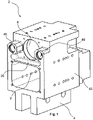
- FIG. 1 shows a monolithic base body 2 according to the invention of a power source module 1 according to the invention.
- the Figures 2 to 6 each show a schematic representation of a power source module 1 according to the invention for joining methods with power generated thermal support.
- a power source module 1 for joining methods with power generated thermal support.
- the power source module 1 in welding tongs, shown in particular for electric spot welding.
- the power source module 1 has the monolithic one-piece base body 2, which in 1 is shown on.
- the base body 2 also has, as in figure 1 shown, a first immovable fastener 4 is formed for connecting a first joining tool.
- a first immovable fastener 4 is formed for connecting a first joining tool.
- An example is in the 7 and 8th an immovable electrode arm 6 is attached directly to the base body 2 as the first joining tool.
- the monolithic base body 2 consists in particular of a metallic material, preferably steel or aluminum or a steel or aluminum alloy. In order to save weight, it has proven advantageous to form the base body 2 from plastic.
- the base body 2 also has, as in 1 shown, at least one first receiving space 8 is formed, with an actuator having a linearly movable second fastening means 10 for connection to a second joining tool being arranged in the first receiving space 8 .
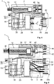
- the schematic representations of Figures 2 to 6 show the actuator in particular in a variant designed as a spindle 12.
- a transformer unit 14 for the electrical supply of the joining tool as shown in FIGS Figures 2 to 5 shown schematically arranged.
- the transformer unit 14 consists in particular of a primary coil, a secondary coil and a transformer core.
- the transformer unit 14 is preferably supplied with AC voltage at frequencies of 500-20,000 Hz from an upstream converter 16.
- the power source module 1 or the base body 2 preferably has outside of the power source module 1 accessible power connections 18.
- the power connections 18 are expediently connected to electrical conductors via the rectifying device on the secondary side of the transformer unit 14 .
- the power source module 1 has two power connections 18, a positive pole connection and a negative pole connection, which are designed in particular as screw, clamp or plug-in connections.
- a current measuring coil 20 is expediently connected to the conductor connecting the power connections 18 to the secondary side of the transformer unit 14, with the signals from the current measuring coil 20 being able to be called up in particular via a control line plug 22, which is preferably accessible from outside the power source module 1.
- the converter 16 can correspond to the Figures 2, 3 and 5 be arranged separately from the power source module 1, usually a control cabinet, not shown.
- the power source module 1 has an electrical primary circuit 24 which connects the transformer unit 14 to a supply connection.
- the supply connection is preferably designed as a primary plug 26a at a point that is accessible from outside the power source module 1 .
- the converter 16 is integrated in the power source module 1 or in the monolithic base body 2 .
- an electrical primary connection 26 between a supply connection and the transformer unit 14 can be omitted, and the converter 16 can be connected directly to the transformer unit 14 with electrical lines.
- the supply connection is preferably also designed as a primary plug 26b at a point that is accessible from outside the power source module 1, similarly to the aforementioned example.
- a three-phase AC power supply with an additional ground connection is preferably present at the primary plug 26b.
- the electrical components for generating a welding current in particular the transformer unit 14, the converter 16 and a rectifier device, respectively embedded separately in individual components in the monolithic base body 2 independently of one another. It is known from the prior art to combine the electrical components at least partially as an assembly with a common housing and to fasten them to a carrier. In the light of the invention, such a grouping is disadvantageous, since a large installation space has to be made available and the development of heat is increasingly centered.
- the advantageous arrangement in the monolithic base body 2 enables the electrical components to be equalized and separated, so that no housing is required for the respective components, the installation space of the receiving space 8, 9 is ideally used and the heat generation is better distributed over a more scattered space and on the base body 2 can be transferred.
- the transformer unit 14 is preferably bonded to the base body 2 .
- the integral connection of the transformer unit 14 to the base body 2 prevents loosening and incorrect reinsertion.
- the connection is designed in such a way that non-destructive separation of the transformer unit 14 from the base body 2 is not possible or is only possible with great difficulty. Defects and defects with regard to the arrangement and storage can advantageously be recognized more easily as a result.
- the transformer unit 14 is particularly preferably cast in the receiving space 8, 9, so that the hardening casting compound is connected to the base body 2 or the receiving space 8, 9 in a materially bonded manner. It is known from conventional transformer units that they are cast in a housing. These ready-made transformer units are used to be used and installed in power source modules of the known type. By means of the direct encapsulation of the transformer unit 14 in the receiving space of the base body 2, a separate housing for the transformer unit 14 is not necessary. Furthermore, the facility and cooling of the transformer unit 14 and the weight of the power source module 1 are improved.
- the casting compound can be a suitable casting resin.
- a rectifying device is arranged in the first or a further receiving space 8 , 9 and is electrically connected to the transformer unit 14 .
- the rectifying device 30 preferably has diodes which are accessible from outside the base body 2 and are designed to be exchangeable individually or together.
- the transformer unit 14 and the rectifier device are each arranged separately from one another in a second receiving space 9 and are electrically connected by means of power connection connections.
- the second receiving space 9 is accessible from the front and the rear, so that the second receiving space 9 is designed as an opening leading through the base body 2 .
- the diodes in the embodiment of the base body 2 according to 1 can be assembled and disassembled on the front side of the base body 2, in particular by means of electrical plug-in contacts.
- the base body 2 has an opening in a side wall of the second accommodation space, so that the diodes are accessible perpendicularly to the second accommodation space 9 . This facilitates access to the diodes, particularly when the joining tools are assembled.
- the diodes are arranged in a separate additional receiving space, which has a separate access for a user in the base body 2 .
- rectifier circuit in the form of 2, 4, 6 or 8 rectifier diodes is used.
- the power source module 1 preferably has a drive unit which is arranged in operative connection with the actuator on the base body 2 so that the actuator can move the second fastening means 10 linearly.
- a drive unit which is arranged in operative connection with the actuator on the base body 2 so that the actuator can move the second fastening means 10 linearly.
- FIGs 2 to 5 different options for implementing the drive with an electric motor 32 are shown.
- figure 5 shows one in particular preferred embodiment, according to which the drive unit is arranged together with the actuator in a receiving space 8 of the base body 2.
- the invention is not limited to an electric motor 32 as a drive unit.
- the drive unit such as the electric motor 32, outside of the base body 2, as in the 7 and 8th to recognize, are mounted directly on the base body 2.
- the actuator is expediently in the form of a spindle 12 and the drive unit in the form of an electric motor 32, as in FIGS Figures 2 to 5 shown, trained.
- the spindle 12 preferably converts a rotational movement of the electric motor 32 into a linear movement of the second fastening means 10 .
- the spindle 12 as in the Figures 2 to 4 shown, have a drive gear 34, in which a corresponding gear on the drive unit can engage.
- the spindle 12 can be connected to the drive unit via a toothed belt which interacts with the drive gear wheel 34 .
- the connections via the drive gear 34 provide simplified movement/power transmission of the drive unit.
- FIG 5 an advantageous variant of a drive unit designed as an electric motor 32 with a spindle 12 as an actuator is shown.
- the electric motor 32 is embedded together with the spindle 12 in a receiving space 8 of the base body 2 .
- the electric motor 32 expediently has a stator 36 and an armature 38 which each enclose a section of the spindle 12 .
- An axis connected to the spindle 12 is connected to a position sensor 40 so that the movement of the spindle 12 can be measured or, in particular, the linear movement of the second fastening means 10 can be determined.
- the power source module 1, as shown in figure 5 shown, an externally accessible first connector 42, which is electrically connected to the position sensor 40, so that a receiving device, z. B. a Control computer, can be connected to the position sensor 40 via a mating connector.
- the power source module 1, as shown in figure 5 shown, an externally accessible second connector 44 which is electrically connected to the electric motor 32.
- the electric motor 32 can be supplied with power via the plug connector, and the motor power can be adjusted by means of a corresponding motor controller.
- the position sensor 40 and the power supply for the electric motor 32 are in the versions of Figures 2 to 4 not shown. It is within the scope of the invention that the Figures 2 to 4 illustrated embodiments also have a corresponding power supply and / or a corresponding position encoder 40. In particular, the position sensor 40 is also not limited to use with an electric motor 32, but can also be implemented in alternative drive concepts, in particular the following drive concepts.
- the drive unit is an electromagnetic linear drive, which can move the actuator and the second fastening means 10 linearly.
- This drive unit is particularly suitable for being mounted directly on the base body 2 , preferably in a receiving space 8 of the base body 2 .
- the magnetic linear drive is preferably connected directly to the second fastening means 10 and contains the actuator as part of the drive.
- the magnetic linear drive replaces the spindle 12, a gear 46 and a drive gear wheel 34, which can arise when the drive unit is designed as an electric motor 49.
- a transmission 46 is preferably operatively connected to the drive unit, which translates a movement of the drive unit to the actuator and, in particular, can adapt the movement to the actuator.
- a gear 46 interposed between a drive gear 34 and the spindle 12, so that the Drive gear 34 transmitted by the drive unit drive sizes are converted into output sizes adapted to the spindle 12.
- the transmission 46 and/or the drive unit is/are advantageously arranged in the first and/or a further receiving space 8 , 9 of the base body 2 .
- the inside 1 shown base body 2 has two receiving spaces 8, 9 on.
- Schematic is in the 2 and 4 shown that in the first receiving space 8, the spindle 12 and a gear 46 are arranged together.
- the spindle 12 is arranged in the first receiving space 8 .
- the spindle 12 and the electric motor 32 are arranged in the first receiving space 8 .
- the Figures 1 to 5 show a base body 2 which has only two receiving spaces 8, 9. A further separation or a different division of the individual components mentioned above, although not shown, is within the scope of the invention.
- the base body 2 has three accommodation spaces.
- the Figures 2 to 5 show an expedient division, with at least the transformer unit 14 being arranged in the second receiving space 9 and at least the linearly movable actuator being arranged in a first receiving space 8 .
- the first receiving space 8 is cylindrical.
- the cylindrical shape is particularly advantageous for the arrangement of a cylindrical actuator.
- the second receiving space 9 is advantageously of cuboid design, providing a very clear installation space which is particularly suitable for the exact positioning and connection of the electrical components and can then advantageously be fully or partially cast with a casting compound.
- the base body 2 preferably has at least one inlet channel for the transport of the casting compound in its wall 55, which opens into at least one receiving space 8, 9.
- the base body 2 preferably has two guide spaces 49 for the arrangement of support means 50.
- These support means 50 serve in particular to carry or support a joining tool and to relieve the load on the second fastening means 10 and the actuator connected to the fastening means 10 .
- 7 shows such a relief, the actuator being relieved as described by the support means 50 absorbing a large part of the load and transferring it to the base body 2.
- a particularly advantageous variant of the power source module 1 is in 6 shown.
- the embodiment shown is characterized by a very effective cooling device. 6 is intended to illustrate the cooling device and can in particular be combined with all of the aforementioned design variants. This in 6
- the power source module 1 shown is connected to the power source module 1, which is figure 5 is shown, ajar.
- the base body 2 assigns accordingly 6 at least one cooling channel 48.
- the example in 6 has at least two cooling channels 48 .
- the cooling channel 48 can carry a fluidic coolant, the cooling channel 48 enabling heat to be transported away from at least one receiving space, in particular from the thermal energy generated by the transformer unit 14, the rectifying device 30 or the drive unit and transferred to the base body 2.
- the cooling duct(s) 48 therefore preferably encloses the components to be cooled.
- the cooling channels 48 can be produced in the base body 2 by appropriate bores. Appropriately, as in 6 indicated, transitions 51 are provided between the cooling channels of the base body 2 to the respective components. In particular, the cooling of the secondary conductors of the transformer unit 14 is advantageous.
- the cooling channels 48 preferably have a galvanic coating as protection against corrosion.
- the cooling channels 48 formed in the base body 2 make hose connections that are as long as possible, as in the prior art are known, unnecessary.
- the component is cooled at least via the base body 2 and, if necessary, additionally by means of a transition 50 on the corresponding component itself, which is kept very short by the cooling channel 48 in the base body 2.
- the advantageous cooling device enables optimized cooling without the known open hose connections as well as Advantages in the reduced number of required components, the weight and the minimized installation space.
- a temperature sensor 52 can be arranged in the base body 2 or directly on the respective components at particularly vulnerable points.
- a temperature sensor 52 is arranged in the vicinity of the transformer unit 14, in particular in contact with the transformer unit 14 or the potting compound surrounding the transformer unit 14.
- a temperature sensor 52 is particularly preferably arranged on the rectifier device 30 or its diodes.
- the temperature sensor 52 is in particular connected to a control line plug 22, expediently together with the current measuring coil 20, so that the output signals of the temperature sensor 52 are preferably accessible from outside the current source module 1.
- the cooling device is preferably controlled as a function of temperature by means of the output signal, but the use of the temperature sensor 52 is not limited to coupling to the cooling device;
- the base body 2 has inlet and outlet connections 54 .
- a cooling liquid flows from the inlet connection 54 through the cooling ducts 48 of the base body 2 and through the transformer unit 14. From there the cooling liquid is routed via a transition 51 that is as short as possible back into a cooling duct 48 and from there via a transition 51 that is also short, through the rectifier device 30.
- a further transition 51 leads the cooling liquid into a cooling channel 48, from which it is guided, in particular through the power connection 18, to a joining tool. That or that Joining tool(s) form/form an external cooling circuit.
- the cooling liquid from the external power circuit is fed back into a cooling channel 48 in the base body 2 via a further connection, in particular the power connection 18 .
- cooling channels 48 still lead the cooling liquid through the drive unit by means of transitions 51 and finally a cooling channel 48 opens at an outlet connection.
- the coolant can be coolant or water with or without additives.
- the at least one cooling channel 48 is expediently formed in at least one wall 55, preferably in a plurality of walls 55, preferably in all walls 55 of the base body 2, which surrounds the first receiving space 8 and/or further receiving spaces 9. Furthermore, the at least one cooling channel 48 is formed in at least one partition 56 of the base body 2, which separates two receiving spaces from one another. In particular, the partition wall 56 is in 6 not shown, with the partition wall 56 in 1 is shown.
- the at least one cooling channel 48 is particularly preferably configured in the base body 2 in such a way that at least two receiving spaces 8, 9 are surrounded at least on one side by the same cooling channel 48, and the receiving spaces 8, 9 are thermally coupled to one another by means of the cooling channel 48.
- the 7 and 8th show welding tongs 58 according to the invention, in particular for electric spot welding.
- These have a power source module 1 according to one of the aforementioned versions.
- These welding tongs 58 have a first joining tool designed as a stationary electrode arm 6 and a second joining tool designed as a movable electrode arm 60, with the stationary electrode arm 6 being connected to the first fastening means 4 and the movable electrode arm being connected to the second linearly movable fastening means 10 60 is connected.
- the electrode arms 6 , 60 have electrodes 62 which are electrically connected to the transformer unit 14 . Especially one electrode 62 is connected to the positive pole connection and one electrode 62 to the negative pole connection.
- the actuator has the second fastening means 10, which can be moved linearly along an adjustment axis X, the movable electrode arm 60 being formed on the fastening means.
- the movable electrode arm 60 is supported by means of support means 50, so that in particular no load acting perpendicularly to the adjustment axis X acts on the second fastening means 10 or the actuator.
- the moveable electrode arm 60 can thereby move parallel to the adjustment axis X by means of the actuator into a joining position and a rest position.
- the welding tongs 58 is shown, with 9 the first and second joining tool, or the electrode arms 6, 60 are shown separately in connection with one another.
- the welding tongs 58 according to the embodiment in 8 is designed as an X-pincer.
- the immovable electrode arm 6 advantageously has a pivot bearing 66 .
- the movable electrode arm 60 in turn is rotatably mounted on the immovable electrode arm 6 via the pivot bearing 66 .
- this version is from 9 out.
- the moveable electrode arm 60 is expediently pivotably connected to the second fastening means 10 of the actuator by means of a rocker, so that the moveable electrode arm 60 is rotated about the pivot bearing 66 on the immovable electrode arm 6 by means of the linear movement of the second fastening means 10 .
- the pivot bearing 66 has the particular advantage that it also has a supporting function for the movable electrode arm. As a result, only a small force acts perpendicularly or at an angle to the actuating axis X on the second fastening means 10 or the actuator.
- this has at least one cooling channel 48 .
- the cooling channel 48 is preferably, as described, in particular via the power connections 18 with at least one cooling channel 48 of the respective Electrode arm 6, 60 fluidly connected.
- the cooling channels or the at least one cooling channel for cooling the respective electrode 62 of the respective electrode arm 6 , 60 are preferably designed to run as far as the electrode 62 .
- the cooling channel 48 can preferably form a feed and a return for each electrode arm 6, 60.
- one electrode arm 6, 60 is connected to a cooling duct 48 designed as a flow and the other electrode arm 6, 60 is connected to a cooling duct 48 designed as a return, the cooling ducts 48 of the electrode arms being connected to one another externally of the power source module 1 via a cooling bridge are.
- the cooling channel 48 can be integrated in the respective electrode arm 6, 60; alternatively, the respective electrode arm 6, 60 has guide means, e.g. B. a groove 64 or arms to lead along the electrode arm 6, 60 a hose line for conducting the cooling liquid.
- the hose line can replace or supplement a cooling channel in the electrode arm 6 , 60 .
- the supply and return can be divided between the cooling channel in the electrode arm 6, 60 and a hose line along the electrode arm.
- the invention is not limited to the exemplary embodiments shown and described, but also includes all embodiments that have the same effect within the meaning of the invention. It is expressly emphasized that the exemplary embodiments are not limited to all features in combination; rather, each individual partial feature can also have an inventive significance independently of all other partial features. Furthermore, the invention has not yet been limited to the combination of features defined in claim 1, but can also be defined by any other combination of specific features of all the individual features disclosed overall. This means that in principle practically every individual feature of claim 1 can be omitted or replaced by at least one individual feature disclosed elsewhere in the application.
Landscapes
- Engineering & Computer Science (AREA)
- Mechanical Engineering (AREA)
- Robotics (AREA)
- Resistance Welding (AREA)
Applications Claiming Priority (1)
| Application Number | Priority Date | Filing Date | Title |
|---|---|---|---|
| DE102021107020.1A DE102021107020A1 (de) | 2021-03-22 | 2021-03-22 | "Stromquellenmodul für Fügeverfahren" |
Publications (2)
| Publication Number | Publication Date |
|---|---|
| EP4063058A1 true EP4063058A1 (fr) | 2022-09-28 |
| EP4063058B1 EP4063058B1 (fr) | 2024-06-12 |
Family
ID=80738823
Family Applications (1)
| Application Number | Title | Priority Date | Filing Date |
|---|---|---|---|
| EP22161754.1A Active EP4063058B1 (fr) | 2021-03-22 | 2022-03-14 | Module de source d'alimentation pour procédé d'assemblage |
Country Status (4)
| Country | Link |
|---|---|
| US (1) | US20220297225A1 (fr) |
| EP (1) | EP4063058B1 (fr) |
| CN (1) | CN115106634A (fr) |
| DE (1) | DE102021107020A1 (fr) |
Families Citing this family (1)
| Publication number | Priority date | Publication date | Assignee | Title |
|---|---|---|---|---|
| CN115958348A (zh) * | 2022-12-30 | 2023-04-14 | 烟台东方威思顿电气有限公司 | 一种三相电能表互感器的自动化焊接设备 |
Citations (6)
| Publication number | Priority date | Publication date | Assignee | Title |
|---|---|---|---|---|
| GB544494A (en) * | 1939-10-18 | 1942-04-15 | Budd Wheel Co | Improvements in or relating to welding apparatus |
| US2349835A (en) * | 1941-09-25 | 1944-05-30 | Budd Wheel Co | Welding tool |
| US5138129A (en) * | 1990-05-09 | 1992-08-11 | Obara Corporation | Welding transformer in a welding gun for robot |
| DE202006016466U1 (de) | 2006-10-24 | 2006-12-21 | Nimak Gmbh | Basiseinheit für eine Schweißzange zum Elektro-Punktschweißen sowie Schweißzange mit einer solchen Basiseinheit |
| DE202008013881U1 (de) | 2008-10-20 | 2008-12-24 | Nimak Gmbh | Schweißzange zum Elektro-Punktschweißen |
| DE202011052206U1 (de) | 2011-12-06 | 2012-01-19 | Nimak Gmbh | Grundkörper für eine Roboter-Schweißzange |
-
2021
- 2021-03-22 DE DE102021107020.1A patent/DE102021107020A1/de not_active Withdrawn
-
2022
- 2022-03-14 EP EP22161754.1A patent/EP4063058B1/fr active Active
- 2022-03-21 CN CN202210279703.7A patent/CN115106634A/zh active Pending
- 2022-03-21 US US17/699,760 patent/US20220297225A1/en not_active Abandoned
Patent Citations (6)
| Publication number | Priority date | Publication date | Assignee | Title |
|---|---|---|---|---|
| GB544494A (en) * | 1939-10-18 | 1942-04-15 | Budd Wheel Co | Improvements in or relating to welding apparatus |
| US2349835A (en) * | 1941-09-25 | 1944-05-30 | Budd Wheel Co | Welding tool |
| US5138129A (en) * | 1990-05-09 | 1992-08-11 | Obara Corporation | Welding transformer in a welding gun for robot |
| DE202006016466U1 (de) | 2006-10-24 | 2006-12-21 | Nimak Gmbh | Basiseinheit für eine Schweißzange zum Elektro-Punktschweißen sowie Schweißzange mit einer solchen Basiseinheit |
| DE202008013881U1 (de) | 2008-10-20 | 2008-12-24 | Nimak Gmbh | Schweißzange zum Elektro-Punktschweißen |
| DE202011052206U1 (de) | 2011-12-06 | 2012-01-19 | Nimak Gmbh | Grundkörper für eine Roboter-Schweißzange |
Also Published As
| Publication number | Publication date |
|---|---|
| CN115106634A (zh) | 2022-09-27 |
| DE102021107020A1 (de) | 2022-09-22 |
| EP4063058B1 (fr) | 2024-06-12 |
| US20220297225A1 (en) | 2022-09-22 |
Similar Documents
| Publication | Publication Date | Title |
|---|---|---|
| EP3187032B1 (fr) | Onduleur avec un boîtier en plusieurs parties et canal d'air de refroidissement interne | |
| DE69937847T2 (de) | Verteilerkasten für fahrzeuge mit zwei netzwerken mit zwei verschiedenen versorgunsspannungen und fahrzeug mit einem derartigen verteilerkasten | |
| DE112017001202T5 (de) | Elektrische Antriebsvorrichtung und elektrische Servolenkvorrichtung | |
| DE202005022102U1 (de) | Schweissbrenner mit einem Brennergehäuse | |
| DE102015214053A1 (de) | Elektroantriebseinheit, insbesondere für ein Elektrofahrzeug | |
| WO2017060152A1 (fr) | Ensemble batterie de traction | |
| DE102010040399A1 (de) | Gehäuse zur Aufnahme eines elektrischen Antriebs | |
| DE102019133363A1 (de) | Kühlsystem, elektrische Antriebseinheit, Elektrofahrzeug und Verfahren zum Kühlen einer elektrischen Antriebseinheit | |
| DE112012004015T5 (de) | Steuervorrichtung für einen Kraftfahrzeug-Wechselrichter | |
| DE102010055484C5 (de) | Elektrisches Antriebssystem mit gezielter Führung der dominanten Common-Mode-Ströme | |
| DE19703655C2 (de) | Elektrischer Antrieb | |
| DE202018002830U1 (de) | Röntgengenerator | |
| DE102016204460A1 (de) | Leistungselektronikmodul und Fahrzeugantriebsystem | |
| WO2015078464A1 (fr) | Module hybride à électronique de puissance intégrée | |
| EP4063058B1 (fr) | Module de source d'alimentation pour procédé d'assemblage | |
| DE102019208685A1 (de) | Starkstromkabel | |
| DE10309147A1 (de) | Elektrische Antriebseinrichtung mit integriertem Umrichter | |
| EP3824698B1 (fr) | Module de puissance doté d'un dissipateur thermique | |
| WO2022194784A1 (fr) | Système de refroidissement, unité d'entraînement électrique, véhicule électrique et procédé de refroidissement d'une unité d'entraînement électrique | |
| WO2024165104A1 (fr) | Dispositif onduleur pour un essieu électrique d'un véhicule automobile et essieu électrique | |
| DE3012743C2 (de) | Gerät der Schutzart Eigensicherheit | |
| DE102021209864A1 (de) | Antriebsgehäuse und Steckersockel-Baueinheit | |
| DE102019208679A1 (de) | Starkstromkabel | |
| DE102024114285B4 (de) | Kraftfahrzeug mit beweglichem, ferromagnetischem Bauteil | |
| EP3606304A1 (fr) | Convertisseur de courant modulaire |
Legal Events
| Date | Code | Title | Description |
|---|---|---|---|
| PUAI | Public reference made under article 153(3) epc to a published international application that has entered the european phase |
Free format text: ORIGINAL CODE: 0009012 |
|
| STAA | Information on the status of an ep patent application or granted ep patent |
Free format text: STATUS: THE APPLICATION HAS BEEN PUBLISHED |
|
| AK | Designated contracting states |
Kind code of ref document: A1 Designated state(s): AL AT BE BG CH CY CZ DE DK EE ES FI FR GB GR HR HU IE IS IT LI LT LU LV MC MK MT NL NO PL PT RO RS SE SI SK SM TR |
|
| STAA | Information on the status of an ep patent application or granted ep patent |
Free format text: STATUS: REQUEST FOR EXAMINATION WAS MADE |
|
| 17P | Request for examination filed |
Effective date: 20230310 |
|
| RBV | Designated contracting states (corrected) |
Designated state(s): AL AT BE BG CH CY CZ DE DK EE ES FI FR GB GR HR HU IE IS IT LI LT LU LV MC MK MT NL NO PL PT RO RS SE SI SK SM TR |
|
| GRAP | Despatch of communication of intention to grant a patent |
Free format text: ORIGINAL CODE: EPIDOSNIGR1 |
|
| STAA | Information on the status of an ep patent application or granted ep patent |
Free format text: STATUS: GRANT OF PATENT IS INTENDED |
|
| RIC1 | Information provided on ipc code assigned before grant |
Ipc: B23K 11/31 20060101AFI20231201BHEP |
|
| INTG | Intention to grant announced |
Effective date: 20240104 |
|
| GRAS | Grant fee paid |
Free format text: ORIGINAL CODE: EPIDOSNIGR3 |
|
| GRAA | (expected) grant |
Free format text: ORIGINAL CODE: 0009210 |
|
| STAA | Information on the status of an ep patent application or granted ep patent |
Free format text: STATUS: THE PATENT HAS BEEN GRANTED |
|
| AK | Designated contracting states |
Kind code of ref document: B1 Designated state(s): AL AT BE BG CH CY CZ DE DK EE ES FI FR GB GR HR HU IE IS IT LI LT LU LV MC MK MT NL NO PL PT RO RS SE SI SK SM TR |
|
| REG | Reference to a national code |
Ref country code: GB Ref legal event code: FG4D Free format text: NOT ENGLISH |
|
| REG | Reference to a national code |
Ref country code: CH Ref legal event code: EP |
|
| REG | Reference to a national code |
Ref country code: DE Ref legal event code: R096 Ref document number: 502022001008 Country of ref document: DE |
|
| REG | Reference to a national code |
Ref country code: IE Ref legal event code: FG4D Free format text: LANGUAGE OF EP DOCUMENT: GERMAN |
|
| PG25 | Lapsed in a contracting state [announced via postgrant information from national office to epo] |
Ref country code: BG Free format text: LAPSE BECAUSE OF FAILURE TO SUBMIT A TRANSLATION OF THE DESCRIPTION OR TO PAY THE FEE WITHIN THE PRESCRIBED TIME-LIMIT Effective date: 20240612 |
|
| PG25 | Lapsed in a contracting state [announced via postgrant information from national office to epo] |
Ref country code: FI Free format text: LAPSE BECAUSE OF FAILURE TO SUBMIT A TRANSLATION OF THE DESCRIPTION OR TO PAY THE FEE WITHIN THE PRESCRIBED TIME-LIMIT Effective date: 20240612 Ref country code: HR Free format text: LAPSE BECAUSE OF FAILURE TO SUBMIT A TRANSLATION OF THE DESCRIPTION OR TO PAY THE FEE WITHIN THE PRESCRIBED TIME-LIMIT Effective date: 20240612 |
|
| REG | Reference to a national code |
Ref country code: LT Ref legal event code: MG9D |
|
| PG25 | Lapsed in a contracting state [announced via postgrant information from national office to epo] |
Ref country code: GR Free format text: LAPSE BECAUSE OF FAILURE TO SUBMIT A TRANSLATION OF THE DESCRIPTION OR TO PAY THE FEE WITHIN THE PRESCRIBED TIME-LIMIT Effective date: 20240913 |
|
| REG | Reference to a national code |
Ref country code: NL Ref legal event code: MP Effective date: 20240612 |
|
| PG25 | Lapsed in a contracting state [announced via postgrant information from national office to epo] |
Ref country code: ES Free format text: LAPSE BECAUSE OF FAILURE TO SUBMIT A TRANSLATION OF THE DESCRIPTION OR TO PAY THE FEE WITHIN THE PRESCRIBED TIME-LIMIT Effective date: 20240612 |
|
| PG25 | Lapsed in a contracting state [announced via postgrant information from national office to epo] |
Ref country code: LV Free format text: LAPSE BECAUSE OF FAILURE TO SUBMIT A TRANSLATION OF THE DESCRIPTION OR TO PAY THE FEE WITHIN THE PRESCRIBED TIME-LIMIT Effective date: 20240612 |
|
| PG25 | Lapsed in a contracting state [announced via postgrant information from national office to epo] |
Ref country code: NO Free format text: LAPSE BECAUSE OF FAILURE TO SUBMIT A TRANSLATION OF THE DESCRIPTION OR TO PAY THE FEE WITHIN THE PRESCRIBED TIME-LIMIT Effective date: 20240912 Ref country code: LV Free format text: LAPSE BECAUSE OF FAILURE TO SUBMIT A TRANSLATION OF THE DESCRIPTION OR TO PAY THE FEE WITHIN THE PRESCRIBED TIME-LIMIT Effective date: 20240612 Ref country code: HR Free format text: LAPSE BECAUSE OF FAILURE TO SUBMIT A TRANSLATION OF THE DESCRIPTION OR TO PAY THE FEE WITHIN THE PRESCRIBED TIME-LIMIT Effective date: 20240612 Ref country code: GR Free format text: LAPSE BECAUSE OF FAILURE TO SUBMIT A TRANSLATION OF THE DESCRIPTION OR TO PAY THE FEE WITHIN THE PRESCRIBED TIME-LIMIT Effective date: 20240913 Ref country code: FI Free format text: LAPSE BECAUSE OF FAILURE TO SUBMIT A TRANSLATION OF THE DESCRIPTION OR TO PAY THE FEE WITHIN THE PRESCRIBED TIME-LIMIT Effective date: 20240612 Ref country code: ES Free format text: LAPSE BECAUSE OF FAILURE TO SUBMIT A TRANSLATION OF THE DESCRIPTION OR TO PAY THE FEE WITHIN THE PRESCRIBED TIME-LIMIT Effective date: 20240612 Ref country code: BG Free format text: LAPSE BECAUSE OF FAILURE TO SUBMIT A TRANSLATION OF THE DESCRIPTION OR TO PAY THE FEE WITHIN THE PRESCRIBED TIME-LIMIT Effective date: 20240612 Ref country code: RS Free format text: LAPSE BECAUSE OF FAILURE TO SUBMIT A TRANSLATION OF THE DESCRIPTION OR TO PAY THE FEE WITHIN THE PRESCRIBED TIME-LIMIT Effective date: 20240912 |
|
| PG25 | Lapsed in a contracting state [announced via postgrant information from national office to epo] |
Ref country code: NL Free format text: LAPSE BECAUSE OF FAILURE TO SUBMIT A TRANSLATION OF THE DESCRIPTION OR TO PAY THE FEE WITHIN THE PRESCRIBED TIME-LIMIT Effective date: 20240612 |
|
| PG25 | Lapsed in a contracting state [announced via postgrant information from national office to epo] |
Ref country code: NL Free format text: LAPSE BECAUSE OF FAILURE TO SUBMIT A TRANSLATION OF THE DESCRIPTION OR TO PAY THE FEE WITHIN THE PRESCRIBED TIME-LIMIT Effective date: 20240612 |
|
| PG25 | Lapsed in a contracting state [announced via postgrant information from national office to epo] |
Ref country code: PT Free format text: LAPSE BECAUSE OF FAILURE TO SUBMIT A TRANSLATION OF THE DESCRIPTION OR TO PAY THE FEE WITHIN THE PRESCRIBED TIME-LIMIT Effective date: 20241014 |
|
| PG25 | Lapsed in a contracting state [announced via postgrant information from national office to epo] |
Ref country code: PT Free format text: LAPSE BECAUSE OF FAILURE TO SUBMIT A TRANSLATION OF THE DESCRIPTION OR TO PAY THE FEE WITHIN THE PRESCRIBED TIME-LIMIT Effective date: 20241014 |
|
| PG25 | Lapsed in a contracting state [announced via postgrant information from national office to epo] |
Ref country code: PL Free format text: LAPSE BECAUSE OF FAILURE TO SUBMIT A TRANSLATION OF THE DESCRIPTION OR TO PAY THE FEE WITHIN THE PRESCRIBED TIME-LIMIT Effective date: 20240612 |
|
| PG25 | Lapsed in a contracting state [announced via postgrant information from national office to epo] |
Ref country code: EE Free format text: LAPSE BECAUSE OF FAILURE TO SUBMIT A TRANSLATION OF THE DESCRIPTION OR TO PAY THE FEE WITHIN THE PRESCRIBED TIME-LIMIT Effective date: 20240612 |
|
| PG25 | Lapsed in a contracting state [announced via postgrant information from national office to epo] |
Ref country code: IS Free format text: LAPSE BECAUSE OF FAILURE TO SUBMIT A TRANSLATION OF THE DESCRIPTION OR TO PAY THE FEE WITHIN THE PRESCRIBED TIME-LIMIT Effective date: 20241012 |
|
| PG25 | Lapsed in a contracting state [announced via postgrant information from national office to epo] |
Ref country code: CZ Free format text: LAPSE BECAUSE OF FAILURE TO SUBMIT A TRANSLATION OF THE DESCRIPTION OR TO PAY THE FEE WITHIN THE PRESCRIBED TIME-LIMIT Effective date: 20240612 |
|
| PG25 | Lapsed in a contracting state [announced via postgrant information from national office to epo] |
Ref country code: SK Free format text: LAPSE BECAUSE OF FAILURE TO SUBMIT A TRANSLATION OF THE DESCRIPTION OR TO PAY THE FEE WITHIN THE PRESCRIBED TIME-LIMIT Effective date: 20240612 Ref country code: RO Free format text: LAPSE BECAUSE OF FAILURE TO SUBMIT A TRANSLATION OF THE DESCRIPTION OR TO PAY THE FEE WITHIN THE PRESCRIBED TIME-LIMIT Effective date: 20240612 |
|
| PG25 | Lapsed in a contracting state [announced via postgrant information from national office to epo] |
Ref country code: SM Free format text: LAPSE BECAUSE OF FAILURE TO SUBMIT A TRANSLATION OF THE DESCRIPTION OR TO PAY THE FEE WITHIN THE PRESCRIBED TIME-LIMIT Effective date: 20240612 |
|
| PG25 | Lapsed in a contracting state [announced via postgrant information from national office to epo] |
Ref country code: SM Free format text: LAPSE BECAUSE OF FAILURE TO SUBMIT A TRANSLATION OF THE DESCRIPTION OR TO PAY THE FEE WITHIN THE PRESCRIBED TIME-LIMIT Effective date: 20240612 Ref country code: SK Free format text: LAPSE BECAUSE OF FAILURE TO SUBMIT A TRANSLATION OF THE DESCRIPTION OR TO PAY THE FEE WITHIN THE PRESCRIBED TIME-LIMIT Effective date: 20240612 Ref country code: RO Free format text: LAPSE BECAUSE OF FAILURE TO SUBMIT A TRANSLATION OF THE DESCRIPTION OR TO PAY THE FEE WITHIN THE PRESCRIBED TIME-LIMIT Effective date: 20240612 Ref country code: PL Free format text: LAPSE BECAUSE OF FAILURE TO SUBMIT A TRANSLATION OF THE DESCRIPTION OR TO PAY THE FEE WITHIN THE PRESCRIBED TIME-LIMIT Effective date: 20240612 Ref country code: IS Free format text: LAPSE BECAUSE OF FAILURE TO SUBMIT A TRANSLATION OF THE DESCRIPTION OR TO PAY THE FEE WITHIN THE PRESCRIBED TIME-LIMIT Effective date: 20241012 Ref country code: EE Free format text: LAPSE BECAUSE OF FAILURE TO SUBMIT A TRANSLATION OF THE DESCRIPTION OR TO PAY THE FEE WITHIN THE PRESCRIBED TIME-LIMIT Effective date: 20240612 Ref country code: CZ Free format text: LAPSE BECAUSE OF FAILURE TO SUBMIT A TRANSLATION OF THE DESCRIPTION OR TO PAY THE FEE WITHIN THE PRESCRIBED TIME-LIMIT Effective date: 20240612 |
|
| PG25 | Lapsed in a contracting state [announced via postgrant information from national office to epo] |
Ref country code: IT Free format text: LAPSE BECAUSE OF FAILURE TO SUBMIT A TRANSLATION OF THE DESCRIPTION OR TO PAY THE FEE WITHIN THE PRESCRIBED TIME-LIMIT Effective date: 20240612 |
|
| REG | Reference to a national code |
Ref country code: DE Ref legal event code: R097 Ref document number: 502022001008 Country of ref document: DE |
|
| PG25 | Lapsed in a contracting state [announced via postgrant information from national office to epo] |
Ref country code: DK Free format text: LAPSE BECAUSE OF FAILURE TO SUBMIT A TRANSLATION OF THE DESCRIPTION OR TO PAY THE FEE WITHIN THE PRESCRIBED TIME-LIMIT Effective date: 20240612 |
|
| PLBE | No opposition filed within time limit |
Free format text: ORIGINAL CODE: 0009261 |
|
| STAA | Information on the status of an ep patent application or granted ep patent |
Free format text: STATUS: NO OPPOSITION FILED WITHIN TIME LIMIT |
|
| 26N | No opposition filed |
Effective date: 20250313 |
|
| PGFP | Annual fee paid to national office [announced via postgrant information from national office to epo] |
Ref country code: DE Payment date: 20250526 Year of fee payment: 4 |
|
| PG25 | Lapsed in a contracting state [announced via postgrant information from national office to epo] |
Ref country code: SE Free format text: LAPSE BECAUSE OF FAILURE TO SUBMIT A TRANSLATION OF THE DESCRIPTION OR TO PAY THE FEE WITHIN THE PRESCRIBED TIME-LIMIT Effective date: 20240612 |
|
| PG25 | Lapsed in a contracting state [announced via postgrant information from national office to epo] |
Ref country code: MC Free format text: LAPSE BECAUSE OF FAILURE TO SUBMIT A TRANSLATION OF THE DESCRIPTION OR TO PAY THE FEE WITHIN THE PRESCRIBED TIME-LIMIT Effective date: 20240612 |
|
| REG | Reference to a national code |
Ref country code: CH Ref legal event code: H13 Free format text: ST27 STATUS EVENT CODE: U-0-0-H10-H13 (AS PROVIDED BY THE NATIONAL OFFICE) Effective date: 20251023 |
|
| PG25 | Lapsed in a contracting state [announced via postgrant information from national office to epo] |
Ref country code: LU Free format text: LAPSE BECAUSE OF NON-PAYMENT OF DUE FEES Effective date: 20250314 |
|
| REG | Reference to a national code |
Ref country code: BE Ref legal event code: MM Effective date: 20250331 |
|
| PG25 | Lapsed in a contracting state [announced via postgrant information from national office to epo] |
Ref country code: BE Free format text: LAPSE BECAUSE OF NON-PAYMENT OF DUE FEES Effective date: 20250331 |
|
| PG25 | Lapsed in a contracting state [announced via postgrant information from national office to epo] |
Ref country code: CH Free format text: LAPSE BECAUSE OF NON-PAYMENT OF DUE FEES Effective date: 20250331 |
|
| PG25 | Lapsed in a contracting state [announced via postgrant information from national office to epo] |
Ref country code: IE Free format text: LAPSE BECAUSE OF NON-PAYMENT OF DUE FEES Effective date: 20250314 |
|
| PGFP | Annual fee paid to national office [announced via postgrant information from national office to epo] |
Ref country code: AT Payment date: 20260301 Year of fee payment: 5 |
|
| PGFP | Annual fee paid to national office [announced via postgrant information from national office to epo] |
Ref country code: FR Payment date: 20260212 Year of fee payment: 5 |