EP4063064A1 - Module de mise à niveau pourvu de système de serrage - Google Patents
Module de mise à niveau pourvu de système de serrage Download PDFInfo
- Publication number
- EP4063064A1 EP4063064A1 EP22000064.0A EP22000064A EP4063064A1 EP 4063064 A1 EP4063064 A1 EP 4063064A1 EP 22000064 A EP22000064 A EP 22000064A EP 4063064 A1 EP4063064 A1 EP 4063064A1
- Authority
- EP
- European Patent Office
- Prior art keywords
- clamping
- workpiece clamping
- workpiece
- media
- clamping system
- Prior art date
- Legal status (The legal status is an assumption and is not a legal conclusion. Google has not performed a legal analysis and makes no representation as to the accuracy of the status listed.)
- Granted
Links
Images








Classifications
-
- B—PERFORMING OPERATIONS; TRANSPORTING
- B23—MACHINE TOOLS; METAL-WORKING NOT OTHERWISE PROVIDED FOR
- B23Q—DETAILS, COMPONENTS, OR ACCESSORIES FOR MACHINE TOOLS, e.g. ARRANGEMENTS FOR COPYING OR CONTROLLING; MACHINE TOOLS IN GENERAL CHARACTERISED BY THE CONSTRUCTION OF PARTICULAR DETAILS OR COMPONENTS; COMBINATIONS OR ASSOCIATIONS OF METAL-WORKING MACHINES, NOT DIRECTED TO A PARTICULAR RESULT
- B23Q1/00—Members which are comprised in the general build-up of a form of machine, particularly relatively large fixed members
- B23Q1/0009—Energy-transferring means or control lines for movable machine parts; Control panels or boxes; Control parts
- B23Q1/0018—Energy-transferring means or control lines for movable machine parts; Control panels or boxes; Control parts comprising hydraulic means
-
- B—PERFORMING OPERATIONS; TRANSPORTING
- B21—MECHANICAL METAL-WORKING WITHOUT ESSENTIALLY REMOVING MATERIAL; PUNCHING METAL
- B21D—WORKING OR PROCESSING OF SHEET METAL OR METAL TUBES, RODS OR PROFILES WITHOUT ESSENTIALLY REMOVING MATERIAL; PUNCHING METAL
- B21D5/00—Bending sheet metal along straight lines, e.g. to form simple curves
- B21D5/02—Bending sheet metal along straight lines, e.g. to form simple curves on press brakes without making use of clamping means
- B21D5/0209—Tools therefor
- B21D5/0236—Tool clamping
- B21D5/0245—Fluid operated
-
- B—PERFORMING OPERATIONS; TRANSPORTING
- B23—MACHINE TOOLS; METAL-WORKING NOT OTHERWISE PROVIDED FOR
- B23Q—DETAILS, COMPONENTS, OR ACCESSORIES FOR MACHINE TOOLS, e.g. ARRANGEMENTS FOR COPYING OR CONTROLLING; MACHINE TOOLS IN GENERAL CHARACTERISED BY THE CONSTRUCTION OF PARTICULAR DETAILS OR COMPONENTS; COMBINATIONS OR ASSOCIATIONS OF METAL-WORKING MACHINES, NOT DIRECTED TO A PARTICULAR RESULT
- B23Q1/00—Members which are comprised in the general build-up of a form of machine, particularly relatively large fixed members
- B23Q1/0063—Connecting non-slidable parts of machine tools to each other
- B23Q1/0072—Connecting non-slidable parts of machine tools to each other using a clamping opening for receiving an insertion bolt or nipple
Definitions
- the invention relates to a workpiece clamping system for retrofitting, having a mounting plate and a workpiece clamping plate which are detachably connected to one another by means of at least one clamping system.
- the present invention is based on the problem of developing a retrofittable workpiece clamping system. This problem is solved with the features of the main claim.
- at least one energy supply channel is arranged in the workpiece clamping plate, which connects a connection surface of the workpiece clamping plate with at least one first media coupling part.
- At least one media channel in the mounting plate connects a second media coupling part, which can be coupled to the first media coupling part, to at least one clamping device of the clamping system.
- a zero-point clamping system can be temporarily or permanently retrofitted to conventional machines.
- the clamping system secures the position of the workpiece clamping plate relative to the mounting plate, which is fixed on the machine table.
- the media supply of the clamping device of the clamping system, which is arranged in the mounting plate, takes place through the media coupling and the mounting plate.
- the media transferred by the media coupler is transferred to the work holding system from an external source at the interface of the work platen.
- the energy supply to the media coupling is carried out through the workpiece clamping plate.
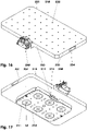
- FIG. 14 shows a machine table (202), for example a machine tool with a workpiece clamping system (210) and with an industrial robot (208).
- FIG. 15 shows a side view of the machine table (202) with the workpiece clamping system (210) arranged thereon.
- the machine table (202) is, for example, a conventional T-slot table for fixing workpieces by means of clamping means held in the T-slots (203). In the illustrated embodiment, the machine table (202) has no media supply.
- the workpiece clamping system (210) comprises a mounting plate (211) and a workpiece clamping plate (231).
- the Aufsetzplatte (211) is in the representations of Figures 14 and 15 mounted on the machine table (202). For example, it is fixed on this with the clamping means mentioned.
- the workpiece clamping plate (231) is held in the mounting plate (211) by means of, for example, several clamping systems (1).
- Workpieces (360) are clamped on the workpiece clamping plate (231). For example, these workpieces (360) are fixed on the workpiece clamping plate (231) by means of a vacuum. Another workpiece fixation is also conceivable.
- the industrial robot (208) is shown in FIG. 14 next to the machine table (202). It is connected to the workpiece clamping system (210) by means of an adapter coupling (290). Energy is transferred from the industrial robot (208) to the workpiece clamping plate (231) by means of the adapter coupling (290). This can be electrical, pneumatic and/or hydraulic energy. Data and signals can also be transmitted between the industrial robot (208) and the workpiece clamping system (210) by means of the adapter coupling (290).
- the Figures 16 and 17 show a top view and a bottom view of the workpiece clamping system (210) with the adapter coupling (290) connected to it.
- the workpiece clamping plate (231) shown as an example is an at least approximately rectangular plate with a large number of suction openings (232) for holding the workpieces.
- the adapter coupling (290) is fixed on an end face (233) of the workpiece clamping plate (231) oriented in the transverse direction (206). This end face (233) is referred to below as the connection surface (233).
- the workpiece clamping plate (231) has, for example, two engaging recesses (234) lying opposite one another.
- the workpiece clamping plate (231) has a length of 1000 millimeters and a width of 550 millimeters.
- the corners of the workpiece clamping plate (231) are, for example, bevelled.
- the thickness of the workpiece clamping plate (231) is 50 millimeters, for example.
- the bottom side (212) of the mounting plate (211) rests on the machine table (202) directly or by means of an adapter.
- the mounting plate (211) is in the workpiece clamping system (210). centrally under the workpiece clamping plate (231).
- the attachment plate (211) has a length of 640 millimeters and a width of 390 millimeters. Its thickness is 48 millimeters, for example.
- Six clamping devices (10), for example, are visible in the mounting plate (211) from the underside (212). These are arranged, for example, in two parallel rows of three clamping devices (10) each, oriented in the longitudinal direction (205).
- channel outlets (214) for example, open out on the end face (213) of the mounting plate (211) oriented in the transverse direction (206). Those channel outlets (214) that are not required for the current operation of the workpiece clamping system (210) can be closed.
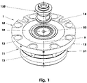
- the figure 1 shows a clamping system (1) consisting of a clamping device (10) and a combination bolt (130).
- the clamping device (10) is integrated in a machine table, for example, to hold a workpiece.
- At least one combination bolt (130) - via which the workpiece can be adapted to the machine table - is usually attached to the workpiece to be clamped.
- the housing (11) of the clamping device (10) contains a mechanism that positions the combination bolt (130) in the clamping device (10) with repeat accuracy. This mechanism includes a wedge mechanism (63, 111) whose drive part is an annular piston (40).
- the housing (11) shown essentially consists of a flange-like housing base body (12) and a housing cover (31) seated on the underside of the housing base body (12). Both parts are made of, for example, rust-, acid- and heat-resistant steel X90CrMoVl8.
- the one-piece housing body (12), e.g. 44 mm high, consists of a flange plate (13) and a cylinder (27) molded onto it.
- the flange plate (13) here has a diameter of 112 mm with a wall thickness of 10 mm.
- the cylinder (27) has an outside diameter of 86 mm with a maximum wall thickness of 6 mm.
- the flange plate (13) and the cylinder (27) have a common center line (9).
- a chamfer (42) measured perpendicularly to the center line (9), e.g. 5.5 mm wide, whose cone angle 120 angular degrees.
- the flange plate (13) has in its outer area, which protrudes beyond the cylinder (27), e.g.
- the countersunk holes are sealed dust-tight with plastic caps. Between every two countersunk holes in the flange plate (13) there are two, e.g. They have a depth of 5.8 mm.
- the single positioning slot (14) is used to block the degree of freedom of rotation about the center line (9) when using only one combination bolt (130).
- the flange plate (13) has a duct system (24) on the left-hand side, via which any dynamic pressure between the flange plate (13) and the workpiece lying on it can be fed to a measuring device via a support control connection (25) in order to check that the workpiece is correctly supported.
- the flange plate (13) has an axial ring groove (29) on its upper side, which is shown in the exemplary embodiment with an inner diameter of, for example, 48 mm and an outer diameter of, for example, 74 mm, has a depth of 0.3 mm. If the workpiece resting on the flange plate (13) completely covers the axial ring groove (29), the dynamic pressure present in the latter can be used for checking.
- the area of the axial ring groove (29) is at least 25% of the workpiece-carrying top of the flange plate (13).
- the flange plate (13), on the upper side of which the respective workpiece rests, has a central receiving recess (20) in the center, which is encased by a support tube (16) formed on the flange plate (13).
- the inwardly projecting support tube (16) has a length of 9.5 mm and a finely machined end face.
- the wall of the support tube (16) facing away from the receiving recess (20) is a finely machined cylindrical surface for the internal guidance of the annular piston (40).
- the receiving recess (20) In its upper area, the receiving recess (20) has a centering clamping surface (21) in the shape of a truncated cone, the cone angle of which is e.g. 30 degrees. The height of the centering clamping surface (21) measures e.g. 5.6 mm. In the lower area, the receiving recess (20) has a gripping shoulder (23) with a wider diameter of e.g. 1 mm.
- the finely machined outer inner wall of the cylinder (27) has a circumferential ventilation groove (28) in the middle area.
- the housing cover (31) is centered over the inner wall of the cylinder (27) and sealed in the housing body (12). In the center it has a stop tube (32) which protrudes into the basic housing body (12) and surrounds a blind-hole-like recess (33) in the closure cap. Latter has a diameter of 28 mm and a depth of 19.3 mm.
- the center lines of the stop tube (32) and the cap recess (33) are on the center line (9).
- the stop tube (32) has at least one finely machined end face.
- the outer wall of the stop tube (32) has a finely machined cylindrical outer wall, the height of which measures 11.5 mm, also for the purpose of guiding the annular piston (40) inside.
- the cover wall adjoining the stop tube (32) has a wall thickness of 10.5 mm, for example.
- the housing cover (31) has twelve blind holes (34) arranged in a circle around the center line (9) for storing and guiding helical compression springs (69).
- the blind holes (34) have a diameter of 10.6 mm with a depth of 7.3 mm.
- the distance between the end faces of the support tube (16) and the stop tube (32) is e.g. 6 mm.
- a clamping ring (100) is arranged between these end faces.
- the clamping ring (100), cf. Figures 8 and 9 is a ring assembled, for example, from three clamping elements (101) and three spring elements (121), the cross section of which is constant over the entire clamping ring (100).
- the segmented clamping elements (101) are made of steel X90CrMoV18.
- the spring elements here are elastomeric bodies (121), which are made of rubber or a rubber substitute material.
- the clamping elements (101) individually cover 85 degrees of angle in the clamping ring (100), while the elastomer bodies (121) cover 35 degrees of angle. In the undeformed state, the clamping ring (100) has an inside diameter of 23 mm and an outside diameter of 35 mm.
- Width Its measurable in the axial direction Width is 0.015 mm less than the distance measured between the faces of the support tube (16) and the stop tube (32). If necessary, the inner diameter of the clamping ring (100) can be elastically expanded to 27 mm, for example, see Figure 5.
- the clamping ring (100) has a heptagonal single cross-section (102). Its width and height are at least almost identical.
- the individual cross section (102) is delimited at the top by a flat clamping surface (105), at the bottom by a flat bearing surface (106), on the inside by a cylindrical inner surface (109) and on the outside by a clamping ring wedge surface (111) in the shape of a truncated cone, see also Figures 8 and 9 .
- the clamping ring wedge surface (111) has a cone angle of 12 degrees.
- a slip-on wedge surface (107) is arranged as a chamfer between the upper clamping surface (105) and the inner surface (109). Their cone angle is 90 degrees.
- the bearing surface (106) merges into the clamping ring wedge surface (111) by means of the clamping ring return stroke surface (112). The latter has a wedge angle of 105 degrees.
- the enveloping clamping surface (108) has a chamfer length of, for example, 2.2 mm, the slip-on wedge surface (107) of, for example, 2.8 mm and the clamping ring return stroke surface (112) of, for example, 2.5 mm.
- the effective width of the clamping ring wedge surface (111) has an effective width of 2.9 mm, taking into account the rounded edges and chamfers.
- an elastomer body (121) sits positively between two clamping elements (101).
- the individual tensioning element (101) has in the area of its flat face, cf. figure 10 , a rear gripping recess (115) into which a front clamping pin (122) of the adjacent elastomeric body (121) engages.
- the rear grip recess (115) is partially a bore (116). It has a diameter of 3 mm and is e.g. 2.3 mm away from the nearest end face of the clamping element (101). Your center line is parallel to the center line (9). The center lines of the bores (116) are 3 mm from the inner surface (109). Between the bore (116) and the front side there is an opening, e.g. 2 mm wide, to form two rear grips (117).
- the respective clamping pin (122) of the elastomer body (121) has a geometric shape that is complementary to the gripping recess (115). The diameter of the individual clamping pin (122) is slightly larger than that of the bore (116) in order to securely hold the six parts of the clamping ring (100) together after assembly.
- the annular piston (40) which can be moved by eg 5.5 mm, is located in the interior of the clamping device (10).
- the latter has an outside diameter of 70 mm and a piston width of 21.5 mm.
- the annular piston (40) has a central piston bore (51) with a minimum inside diameter of 33 mm.
- the front side of the annular piston (41) is gripped in the outer area to match the base of the flange plate (13).
- In the outer wall (47) of the annular piston (40) there are two sealing ring grooves for accommodating sealing rings.
- the piston bore (51) is divided into three areas.
- the front upper area is the upper sealing zone (52) in which a sealing ring (54) is arranged in a sealing ring groove (53).
- the sealing ring (54) rests against the outer wall of the support tube (16).
- the rear lower area is the lower sealing zone (55), in which there is also a sealing ring (57) in a sealing ring groove (56).
- the lower sealing ring (57) contacts the outer wall of the stop tube (32) of the housing cover (31). All sealing rings are quad rings, for example.
- annular groove (61) In the central area of the piston bore (51), between the two sealing zones (52, 55), there is an annular groove (61), which consists of a working section (62) and an immersion section (65).
- the working section (62) has an annular groove wedge surface (63) in the shape of a truncated cone, on which the clamping ring (100) is supported in the radial direction when the combination bolt (130) is clamped.
- the annular groove wedge surface (63) has a cone angle of 12 degrees. It extends in the annular groove (61) over a length of e.g. 4 mm.
- the immersion section (65) at its upper end.
- the latter has a cylindrical groove base, the groove depth of which is 3.5 mm, for example.
- the lower flank of the immersion section in the shape of a truncated cone forms a return stroke surface (66) whose cone angle measures 105 angular degrees.
- the immersion section (65) receives the clamping ring (100) completely when the closure cap (70) passes the clamping ring (100) while it expands as it travels into the closure cap recess (33) of the housing cover (31).
- the transition between the ring groove wedge surface (63) and the return stroke surface (66) is rounded.
- the outer wall (47) of the annular piston (40) can have an oval, an elliptical, a polygonal or a polygonal contour. The same applies to the contour of the inner wall (48).
- the closure cap (70) is a substantially rotationally symmetrical, piston-like component which closes the receiving recess (20) when the clamping device (10) is not in use, cf. Figures 1 to 4 . It is also made of stainless steel X90CrMoV18. Your face is drawn in by 0.3 mm except for a 0.9 mm wide edge.
- the closure cap (70) has a cylindrical outer wall which has a corrugated collar (71) in the lower area, with which it rests on the gripping shoulder (23) of the receiving recess (20) in the closed position. It is penetrated centrally by a stepped bore (72) which tapers in several steps towards the front face.
- the lower area of the stepped bore (72) is a cylinder area (73) which has a diameter of 15 mm.
- An annular groove for a locking ring and at least two overflow notches (74) are located in the wall of the cylinder area (73).
- the cylinder area (73) is adjoined by an air distribution area (75) from which, for example, eight blow-off bores (76) extend to the radial outer wall of the closure cap (70).
- the blow-off holes (76) are all in one plane. They end tangentially in the air distribution area (75), with their center lines tangent to a circle centered on the center line (9) with a diameter of, for example, 10.4 mm.
- blow-out bores (76) results in blow-out in the centering gap that widens upwards (22) a helically winding purge flow.
- the air distribution area (75) is followed by a guide hole (77) with a diameter of 6 mm.
- a spring guide ring groove (81) is worked into the lower half of the closure cap (70) between the outer wall of the closure cap (70) and the stepped bore (72).
- the lower face of the closure cap (70) has a 1.4 x 45° chamfer according to DIN 406-11 as an expanding chamfer (78).
- the guide play of the closure cap (70) in the receiving recess (20) is less than 0.1 mm.
- a cleaning piston Seated in the stepped bore (72), secured axially by a retaining ring, cf. figure 11 , a cleaning piston (85).
- Its piston which is mounted in the cylinder area (73), is guided in a sealed manner with its piston rod (86) in the guide bore (77).
- the piston rod (86) has a through hole (87) which is closed in the piston area, for example by means of a threaded pin.
- a nozzle bore (89) which blows out axially.
- the piston rod (86) has at least one radial bore (88) through which the through bores (87) are supplied with compressed air.
- the combination bolt (130) not yet sunk into the receiving recess (20) is shown above the clamping device (10). It is also made of the rust-resistant steel X90CrMoVl8 and like the clamping elements (101) hardened to 56 + 3 HRC.
- the task of the combination bolt (130) is to clamp the workpiece on the clamping device (10) and at the same time to center it precisely in it. It is a turned part, for example 30 mm long, which has a central through hole (139) with an M10 thread.
- the through hole (139) has a 3 mm deep counterbore on the workpiece side with a diameter of 10.5 mm, for example. At its opposite end, it has a 90° countersink.
- the combination bolt (130) is equipped with a fitted cylinder section (131), the diameter of which measures 18 mm, for example, and the height, for example, 5 mm. It ends in a flat axial contact surface (132).
- the clamping area (133) which has a diameter of, for example, 26.8 mm in a cylindrical section that is, for example, 1.5 mm wide, is used when clamping the workpiece, among other things, as a rear grip that comes to rest on the clamping ring (100).
- it has an inner clamping surface (134) in the shape of a truncated cone, with which it rests over a large area on the enveloping clamping surface (108) of the clamping ring (100) in the clamped state.
- the effective flank length of the inner clamping surface (134) is at least 2.4 mm, taking into account the rounding and rounding.
- clamping ring return stroke chamfer (135) Between the cylindrical section and the front face of the clamping area (133) there is a clamping ring return stroke chamfer (135), the cone angle of which is 90 degrees. It makes it easier for the expanded clamping ring (100) to pass when the combination bolt (130) is driven into the receiving recess (20).
- the centering area (137) of the combination bolt (130) has one of the inner clamping surface (134) facing the finely machined outer clamping surface (138) for centering on the centering clamping surface (21) of the receiving recess (20) - according to the figures 6 and 7 - fits over a large area.
- the effective flank length is at least 5.4 mm, taking into account the rounding and rounding.
- the maximum diameter of the outer clamping surface (138) measures 29.8 mm, for example.
- the waist area (136) has a diameter of eg 22 mm. In this area there are two opposite flat areas, cf. figure 1 , in order to have two contact surfaces for a spanner with a width across flats of 20.
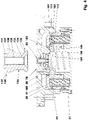
- the clamping device (10) is depressurized in its non-actuated initial state.
- the closure cap (70) is in its closed position.
- the annular piston (40) rests against the bottom of the cylinder (27) due to the action of the helical compression springs (69).
- the clamping ring (100) contacts the annular groove wedge surface (63) of the annular piston (40).
- the clamping ring (100) protrudes approximately halfway into the receiving recess (20).
- the closure cap (70) with its expanding chamfer (78) is at a distance of approx. 0.1 mm, which prevents the closure cap (70) from opening in a form-fitting manner.
- the cleaning piston (85) is in the closing cap (70) in its retracted position.
- the target pneumatic pressure is present at the rear piston head (45) of the annular piston (40).
- compressed air reaches the receiving recess (20) via the transverse bore (35).
- cleaning piston (85) in the sealing cap (70) acts on the cleaning piston (85) in the sealing cap (70), whereby this is pressed upwards in the stepped bore (72).
- the compressed air flows via the overflow notches (74) via the air distribution area (75) into the blowing-out bores (76) and via the through-bore (87) of the piston rod (86) into the extended nozzle bores (89) for blowing-out the end face of the closure cap (70).
- the clamping ring (100) and the annular piston (40) seal the gap between the support tube (16) and the stop tube (32).
- the combination bolt (130) is already largely immersed in the receiving recess (20) with the closure cap (70) being advanced against the action of the closing spring (82).
- the clamping area (133) of the combination bolt (130) presses - while stretching the elastomer body (121) of the Clamping ring (100) - the clamping ring (100) in the immersion section (65) of the annular piston (40).
- the stretching of the elastomer body (121) has also caused the closure cap (70) shortly beforehand.
- the combination bolt (130) with its outer clamping surface (138) has come into full contact with the centering clamping surface (21) of the flange plate (13).
- the axial contact surface (132) of the combination bolt (130) now lies in the plane in which the contact points of the upper side of the flange plate (13) facing the workpiece lie.
- the clamping ring (100) has contracted into its initial position, with which it has largely left the immersion section (65) of the annular piston (40) on the one hand and, on the other hand, rests with its enveloping clamping surface (108) on the inner clamping surface (134) of the piston pin (130).
- the sealing cap (70) is at a small distance, for example 0.1 mm, in front of the bottom of the sealing cap recess (33) of the housing cover (31).
- a tensile force acting on the combination bolt (130) is introduced into the clamping ring (100) via the clamping area (133), from where it is transmitted via the flat clamping surface (105) to the end face of the stop tube (32) and thus to the housing (11). to become.
- the measurement deviation from clamping process to clamping process is less than 5 ⁇ m.
- the pull-in force is in the range of 18 kN.
- the combination bolt (130) is loosened essentially in the reverse order.
- the annular piston (40) is pressed against the housing cover (31) with compressed air, which forces the clamping ring (100) into the immersion section (65) of the annular piston (40) when the piston pin (130) is pulled out.
- the truncated cone-shaped enveloping clamping surface (108) of the combination bolt (130) facilitates this process.
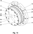
- the figure 13 shows the back of the clamping device (10).
- the compressed air can be fed into the clamping device (10) in two different housing areas.
- the usual area of the housing is the underside of the housing cover (31), on which, for example, four connections for compressed air hoses are provided.
- the compressed air in the housing (11) is conveyed in front of the ring piston front side (41) via this connection.
- the compressed air passes radially through the annular piston (40) into the immersion section (65), to flow from there along the clamping ring (100) between the support tube (16) and the stop tube (32) into the receiving recess (20).
- a clamping compressed air connection (36) through which compressed air can be applied to the bottom of the annular piston (45) in order to support the clamping movement of the annular piston (40).
- the blow-off port (38) is only used if the tensioner (10) is not equipped with a locking cap (70). Compressed air is then blown from the bottom of the closure cap recess (33) in the direction of the receiving recess (20) in order to convey dirt particles located there to the outside.
- connections are provided on the back of the flange or the flange plate (13) for hose-free connection of the compressed air. These connections are supplied from holes located in the tensioner support (10).
- the connections are the unlocking compressed air connection (17), the blow-out connection (18), the sealing air connection (19), the clamping compressed air connection (26) and a support control connection (25), cf figure 2 .
- the clamping elements (101) arranged in the clamping device (10) come into full contact with the combination bolt (130) with their clamping surfaces (105, 108). This results in relatively low surface pressures even with high pull-in forces.
- the large contact surfaces guarantee a high degree of dimensional stability of the entire system, which means that the clamping device (10) can also easily support large load moments via the combination bolt (130).
- the segment-like clamping elements (101) are elastically coupled in the circumferential direction via the elastomer bodies (121) of the clamping ring (100).
- the annular piston (40) is moved by means of spring force into the clamping position of the clamping device (10) and is held there. If necessary, the clamping process is supported with the help of compressed air.
- Compressed air is used to relieve the tensioned clamping ring (100) and to retract the annular piston (40) - to release the combination bolt (130).
- the interior of the clamping device (10) is placed under sealing air in order to prevent chips, coolants or lubricants from penetrating during the machining of the workpiece. If necessary, hydraulic oil can also be used to move the annular piston (40).
- FIG 18 a cross section of the workpiece clamping system (210) through the clamping devices (10) is shown.
- the workpiece clamping plate (231) and the mounting plate (211) are connected to one another by means of the clamping systems (1).
- the combination bolts (130) are arranged on the underside of the workpiece clamping plate (231) and protrude downwards out of it.
- the clamping devices (10) sit in the mounting plate (211).
- the sealing caps (70) point upwards.
- the adapter coupling (290) is arranged on the workpiece clamping plate (231) on the left-hand side of this representation.
- the adapter coupling (290) has at least one locking device (291) on the robot side and at least one first energy transfer coupling part (312).
- the energy transfer coupling part (312) is above the locking device (291). It has a power supply connection (311) on the robot side.
- the adapter coupling (290) has at least one second energy transfer coupling part (331) and a docking block (351) with at least one locking bolt (352), cf. figure 23 .
- the second energy transfer clutch part (331) is arranged above the docking block (351).
- the docking coupling (292) constructed from the locking device (291) and the locking bolt (352) is constructed, for example, similarly to that in connection with Figures 1 - 13 described clamping system (1).
- the docking coupling (292) is shown, for example, without a sealing cap.
- a sectional view of the locking device (291) is shown. It has a locking piston (294) which is loaded by compression springs (293) and on which a locking ring (295) rests.
- the locking piston (294) can, for example, be loaded pneumatically against the compression springs (293), so that the locking piston (294) is moved to the left relative to the locking housing (296) in this illustration.
- a locking notch (297) of the locking piston (294) thus reaches the area of the locking ring (295).
- the locking ring (295) the structure of which corresponds to that of the clamping ring (100), expands into the locking notch (297) when the elastomer body (298) is relieved.
- the locking device (291) is released to receive the locking bolt (352) or to remove the locking bolt (352).
- the adapter coupling (290) has two docking couplings (292), each of which includes a locking device (291) and a locking bolt (352).
- the first energy transmission part (312) and the second energy transmission part (331) comprehensive energy transmission clutch (330) is in figure 18 shown in coupled condition.
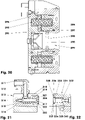
- the figure 21 shows the first energy transmission part (312) and the figure 22 the second energy transmission part (331) for example a pneumatic energy transmission clutch (330).
- the device has two energy transmission clutches (330).
- the robot-side power supply part (313) has a line housing (314) on the top of which the power supply connection (311) is arranged.
- the line housing (314) has a stepped recess (315) in which a central bolt (316) is fastened.
- This central bolt (316) is, for example, a countersunk screw whose head (317) has an imaginary cone angle of 30 degrees.
- a spring energy accumulator (318) referred to below as the closing spring (318), is supported in the stepped recess (315) and loads a closing slide (319) surrounding the central bolt (316).
- the closing spring (318) is designed as a compression spring (318).
- the closing slide (319) has an axial sealing ring (322) on its free end face (321).
- a radial sealing element can be arranged on the lateral surface of the closing slide (319).
- the locking slide (319) has a conical recess (323), the gradient of which corresponds to the cone angle of the central bolt (316).
- the end face (321) of the locking slide (319) is, for example, flush with the central bolt (316).
- the Indian figures 18 and 24 The recognizable gap-shaped closure channel (324) between the two components is closed.
- the second energy transfer clutch part (331) has a spring-loaded locking tappet (332) with a cylinder head (333).
- This locking tappet (332) is slidably guided in a valve housing (334).
- the spring energy store (335) loading the cylinder head (333) in the form of a compression spring (335) is supported on the valve housing (334).
- This compression spring (335) has, for example, a higher spring constant than the closing spring (318) of the first energy transfer clutch part (312).
- the coupling of the adapter coupling (290) is shown.
- the locking bolts (352) of the docking coupling (292) first engage in the locking recesses (299) of the locking devices (291).
- the two coupling partners are mutually centered.
- the locking pin (352) will pass the locking ring (295).
- the central bolt (316) of the energy transfer clutch (330) strikes the locking plunger (332).
- the valve housing (334) hits the closing slide (319).
- the central bolt (316) moves the locking plunger (332) against the pressure of the compression spring (335).
- the locking slide (319) is pushed against the load of the locking spring (318) on the robot side.
- the robot-side closure channel (324) is first opened so that air flows out.
- the line channel (339) on the clamping plate side is also closed by means of the closing plunger (332) and the sealing ring (336). This can be used to clean the clutch area.
- the locking tappet (332) is pushed out of the area of the sealing ring (336) as you continue to approach.
- the duct (339) is released.
- the energy transfer clutch (330) is sealed off from the environment (201).
- the docking coupling (292) is locked.
- the compressed air provided by the industrial robot (208) flows through the energy supply connection (311), the energy transfer coupling (330) and through channels (341, 353) in the second energy supply coupling part (331) and in the docking block (352) into the workpiece clamping plate (231 ).
- the figure 19 shows a cross section of the workpiece clamping system (210).
- the sectional plane of this representation is parallel to the sectional plane of the representation figure 18 .
- the sectional plane is offset in the direction of the vertical central transverse plane of the workpiece clamping system (210) by half a pitch of the clamping units (1) to the sectional plane of the figure 18 .
- An energy supply channel (236) is stamped into the workpiece clamping plate (231). This runs, for example, parallel to the underside (237) of the workpiece clamping plate (231) and ends in a vertically aligned connecting channel (238).
- the energy supply channel (236) opens into a media coupling (250).
- this media coupling (250) connects the workpiece clamping plate (231) to the mounting plate (211), so that the medium fed into the workpiece clamping plate (231) is guided into a media channel (215) in the mounting plate (211).
- the media channel (215) is part of a channel system (216) stamped into the mounting plate (211). This channel system (216) consists of several horizontal channels (217) and vertical channels (218) connecting the media coupling (250) to the tensioners (10).
- the workpiece clamping system (210) has two media couplings (250). These media couplings (250) are arranged, for example, in the vertical central longitudinal plane of the workpiece clamping system (210) symmetrically to its vertical central transverse plane. For example, they are identical to each other.
- the channel systems (216) of both media couplings (250) can be routed separately from one another.
- the individual channels can be arranged next to one another or one above the other.
- the channels can cross. However, it is also conceivable that individual channels intersect.
- the channel systems (216) of both media couplings can be brought together.
- the same energy, data and signals can be transmitted via the individual media coupling (250) as via the individual energy transfer coupling (330).
- the mounting plate (211) is downstream of the workpiece clamping plate (231) in the direction of flow.
- the single media coupling (250) has a first media coupling part (251) arranged on the workpiece mounting plate (231) and a second media coupling part (271) arranged on the mounting plate (211).
- the first media coupling part (251) is designed as a bolt part (251) in the exemplary embodiment.
- the bolt part (251), cf Figures 25 and 26 has a fixed part (252) and a valve slide (253) that can be moved spring-loaded relative thereto.
- the fixed part (252) has an insert cover (255) with a central opening (256) on its upper side (254). This breakthrough (256) connects the energy supply channel (236) with the assembled state Line space (257) of the bolt part (251).
- the fixed part (252) is screwed to the workpiece clamping plate (231), for example, with a fastening collar (258).
- the fixed part (252) protrudes from the fastening collar (258) with a tubular, central pin (259).
- Stop webs (263) are located between the radial channels (262).
- the stop surfaces (264) of the stop webs (263) are arranged, for example, perpendicular to the vertical direction (207) of the media coupling (250).
- the inner wall of the pin (259) is in the form of a hollow truncated cone in the area adjacent to the free end face.
- the cone angle opened in the direction of the line space (257) is 60 degrees, for example.
- the valve slide (253) has a spring seat (265) and is designed in its upper area to complement the area of the pin (259) in the shape of a hollow truncated cone. Between the valve slide (253) and the pin (259) is in the representations of figures 19 and 25 an air duct (266) is shown.
- a spring energy store (267) in the form of a compression spring (267) rests on the spring receptacle (265). This is supported on the insert cover (255). The compression spring (267) loads the valve slide (253) in the direction of the end face of the pin (259), so that the air duct (266) is closed when the compression spring (267) is relieved.
- Leakage monitoring can be provided in the bolt part (251) and/or in the workpiece clamping plate (231). This includes, for example, a pressure switch that triggers an alarm when the pressure falls below a threshold value.
- the pot slide (273) is an item in the figure 27 shown. It has a two-tier pot construction, with the diameter of the lower section being larger than the diameter of the upper section.
- the upper area has radially oriented openings (279).
- the cup slide (273) has a central star bolt (282) on its upper side (281). This star bolt (282) is surrounded by a thrust surface (283).
- the cup slide (273) is supported on a receiving spring (284).
- the receiving spring (284) is a spring energy store (284) in the form of a compression spring.
- the spring constant of this receiving spring (284) is, for example, higher than the spring constant of the compression spring (267) of the bolt part (251) upstream in the direction of flow.
- the cup slide (273) has radially oriented recesses (285). When the receiving part (271) is mounted, these recesses (285) are located, for example, in front of the media channels (215).
- the Figures 28 - 33 show the coupling of the workpiece clamping plate (231) to the mounting plate (211).
- the workpiece clamping plate (231) and the mounting plate (211) are decoupled from one another.
- the combination bolt (130) and the bolt part (251) protrude downwards.
- the combination bolt (130) protrudes in the representation of figure 28 the combination bolt (130) further out of the workpiece clamping plate (231) by one third of the length of the bolt part (251) than the bolt part (251).
- the receiving part (271) and the clamping device (10) are relieved, cf. figure 2 .
- the cup slide (273) is in its highest position. It closes the receiving housing (272).
- the figure 30 shows the mounting plate (211) and the workpiece clamping plate (231) as they come closer.
- the valve slide (253) of the media coupling (250) makes contact with the star bolt (282) of the receiving part (271).
- the combination bolt (130) has pushed the locking cover (70) further down.
- the clamping system (1) centers the position of the workpiece clamping plate (231) relative to the mounting plate (211).
- valve slide (253) continues to rest against the cup slide (273), which, for example, remains in the receiving housing (272) by means of its compression spring (284).
- the housing interior (275) is thus still sealed against the environment (1).
- the pin (259) has placed its stop surfaces (264) on the thrust surface (283) of the cup slide (273). That's it
- the valve slide (253) is shifted relative to the fixed part (252) so that the air duct (266) is open.
- the compressed air conveyed via the robot arm (209) for example, is guided through the energy supply channels (236) into the line space (257) of the bolt part (251).
- This compressed air flows through the air channel (266) and flows through the radial channels (262) into the environment (1).
- the area around the media coupling is cleaned of contamination, e.g. chips, dust, moisture, etc.
- the combination bolt (130) has pushed the sealing cover so far that it rests against the clamping ring (100).
- the figure 32 shows the workpiece clamping system (210) with further approximated subassemblies.
- the bolt part (251) has penetrated further into the receiving part (271) with displacement of the cup slide (273).
- the inner sealing ring (278) now seals the pin (259) against the receiving housing (272).
- the compressed air conveyed through the workpiece clamping plate (231) is now conveyed through the receiving part (271) into the media channels (215).
- the annular piston (40) for example, is lowered by means of this compressed air, so that the clamping ring (100) can expand.
- the workpiece clamping system (210) is shown with the clamping system (1) locked and the media coupling (250) closed.
- the combination bolt (130) engages behind the clamping ring (100).
- the bolt part (251) is immersed in the receiving part (271).
- the compressed air transmitted via the media coupling (250) can now be used, for example, for workpiece or processing-specific applications. It is also conceivable to open the adapter coupling (290).
- the industrial robot (208) from the workpiece clamping system (210) separately. This interrupts the compressed air supply.
- the workpiece clamping system (210) is mechanically locked so that it does not come loose. Even if the compression springs (69, 82, 91, 267, 284) of the media coupling (250) or the clamping system (1) become tired, the functionality of the workpiece clamping system (210) is not impaired.
- the industrial robot (208) In order to change the workpiece clamping plate (231) with workpieces (360) fixed thereon, the industrial robot (208), for example, is connected to the connection surface (233) by means of the adapter coupling (290), as described above.
- the clamping devices (10) for releasing the clamping systems (1) can be pressurized by means of the compressed air routed through the workpiece clamping plate (231), the media couplings (250) and the mounting plate (211).
- the workpiece clamping plate (231) can now be lifted off, for example, by means of the industrial robot (208), which is connected to the workpiece clamping plate (231) via the adapter coupling (290). Subsequently, for example, a new workpiece clamping plate (231) provided with workpieces (360) to be machined can be inserted into the mounting plate (211).
Landscapes
- Engineering & Computer Science (AREA)
- Mechanical Engineering (AREA)
- Jigs For Machine Tools (AREA)
- Clamps And Clips (AREA)
Applications Claiming Priority (1)
| Application Number | Priority Date | Filing Date | Title |
|---|---|---|---|
| DE102021001469.3A DE102021001469A1 (de) | 2021-03-22 | 2021-03-22 | Nachrüstgruppe mit Spannsystem |
Publications (3)
| Publication Number | Publication Date |
|---|---|
| EP4063064A1 true EP4063064A1 (fr) | 2022-09-28 |
| EP4063064C0 EP4063064C0 (fr) | 2025-08-13 |
| EP4063064B1 EP4063064B1 (fr) | 2025-08-13 |
Family
ID=80930495
Family Applications (1)
| Application Number | Title | Priority Date | Filing Date |
|---|---|---|---|
| EP22000064.0A Active EP4063064B1 (fr) | 2021-03-22 | 2022-03-21 | Module de type retrofit pourvu de système de serrage |
Country Status (2)
| Country | Link |
|---|---|
| EP (1) | EP4063064B1 (fr) |
| DE (1) | DE102021001469A1 (fr) |
Cited By (1)
| Publication number | Priority date | Publication date | Assignee | Title |
|---|---|---|---|---|
| EP4491324A1 (fr) * | 2023-07-11 | 2025-01-15 | System 3R International AB | Système de serrage appliqué pour une machine-outil |
Citations (3)
| Publication number | Priority date | Publication date | Assignee | Title |
|---|---|---|---|---|
| EP1050363A2 (fr) * | 1999-05-04 | 2000-11-08 | Emil Stark | Système d'accouplement pour connecter les lignes d'alimentation de toutes sortes, y compris lignes électriques, entre une machine-outil et un support de pièces couplé à celle-ci |
| EP2246608A1 (fr) * | 2008-02-18 | 2010-11-03 | Pascal Engineering Corporation | Dispositif de raccordement de trajet de fluide |
| DE102018009226A1 (de) | 2018-11-26 | 2020-05-28 | Günther Zimmer | Spannsystem aus einer Spannvorrichtung und einem Kombibolzen |
Family Cites Families (3)
| Publication number | Priority date | Publication date | Assignee | Title |
|---|---|---|---|---|
| DE3232367A1 (de) | 1982-08-31 | 1984-03-01 | Friedrich Deckel AG, 8000 München | Einrichtung zum anschluss einer auf einer werkstueckpalette angeordneten hydraulischen spannvorrichtung |
| DE10317339B9 (de) | 2003-04-15 | 2017-09-28 | Andreas Maier Gmbh & Co. Kg | Spannsystem mit Adapterteil |
| DE102018128883B4 (de) | 2018-11-16 | 2022-04-21 | Stark Spannsysteme Gmbh | Palettengreifer und zugehöriges Betriebsverfahren |
-
2021
- 2021-03-22 DE DE102021001469.3A patent/DE102021001469A1/de active Pending
-
2022
- 2022-03-21 EP EP22000064.0A patent/EP4063064B1/fr active Active
Patent Citations (3)
| Publication number | Priority date | Publication date | Assignee | Title |
|---|---|---|---|---|
| EP1050363A2 (fr) * | 1999-05-04 | 2000-11-08 | Emil Stark | Système d'accouplement pour connecter les lignes d'alimentation de toutes sortes, y compris lignes électriques, entre une machine-outil et un support de pièces couplé à celle-ci |
| EP2246608A1 (fr) * | 2008-02-18 | 2010-11-03 | Pascal Engineering Corporation | Dispositif de raccordement de trajet de fluide |
| DE102018009226A1 (de) | 2018-11-26 | 2020-05-28 | Günther Zimmer | Spannsystem aus einer Spannvorrichtung und einem Kombibolzen |
Cited By (1)
| Publication number | Priority date | Publication date | Assignee | Title |
|---|---|---|---|---|
| EP4491324A1 (fr) * | 2023-07-11 | 2025-01-15 | System 3R International AB | Système de serrage appliqué pour une machine-outil |
Also Published As
| Publication number | Publication date |
|---|---|
| EP4063064C0 (fr) | 2025-08-13 |
| EP4063064B1 (fr) | 2025-08-13 |
| DE102021001469A1 (de) | 2022-09-22 |
Similar Documents
| Publication | Publication Date | Title |
|---|---|---|
| DE102014119482B4 (de) | Werkzeugspanneinrichtung, Werkzeughalter und Werkzeugträger | |
| EP3887095B1 (fr) | Système de serrage composé d'un dispositif de serrage et d'un boulon combiné | |
| DE19525574C1 (de) | Spannvorrichtung zum genauen gegenseitigen Fixieren zweier Bauteile | |
| EP0911112A1 (fr) | Dispositif combiné de centrage et serrage actionnable par fluide sous pression, utilisable en particulier pour la construction de carrosseries automobile dans l'industrie automobile | |
| DE3807140C2 (fr) | ||
| DE102011054063B4 (de) | Antriebsvorrichtung für ein Stützteil zum Abstützen eines Werkstücks | |
| EP3957432A1 (fr) | Mandrin | |
| EP1738864A2 (fr) | Dispositif de serrage | |
| DE102007045687A1 (de) | Trennbare mechanische Kupplung | |
| DE10002395A1 (de) | Spanneinrichtung | |
| EP3887089B1 (fr) | Système de serrage avec un dispositif de serrage à course surveillée | |
| EP3403758B1 (fr) | Adaptateur réglable | |
| EP3043954B1 (fr) | Dispositif de serrage d'au moins un téton de serrage | |
| EP4063064B1 (fr) | Module de type retrofit pourvu de système de serrage | |
| EP3455516B1 (fr) | Dispositif de freinage et/ou de serrage comprenant un module d'actionnement et un module d'accouplement d'arbre | |
| EP3515659A1 (fr) | Montage en série d'un dispositif de serrage | |
| DE10317339B9 (de) | Spannsystem mit Adapterteil | |
| DE10118808A1 (de) | Schnellspann-Einrichtung mit Kugelführung | |
| DE4220873C2 (de) | Vorrichtung zur lösbaren Verbindung zweier Teile | |
| DE102012011760B4 (de) | Modulare Schnittstelle für Werkzeuge mit quer zur Axialrichtung wirkenden Strukturpaaren | |
| WO2004033146A1 (fr) | Dispositif de montage | |
| DE9405030U1 (de) | Palettenspannsystem | |
| EP4385659B1 (fr) | Dispositif de serrage | |
| EP1313584B1 (fr) | Dispositif d'actionnement pour systeme de serrage d'outil ou de piece dans une broche de machine-outil | |
| DE9002248U1 (de) | Dehnspannvorrichtung |
Legal Events
| Date | Code | Title | Description |
|---|---|---|---|
| PUAI | Public reference made under article 153(3) epc to a published international application that has entered the european phase |
Free format text: ORIGINAL CODE: 0009012 |
|
| STAA | Information on the status of an ep patent application or granted ep patent |
Free format text: STATUS: THE APPLICATION HAS BEEN PUBLISHED |
|
| AK | Designated contracting states |
Kind code of ref document: A1 Designated state(s): AL AT BE BG CH CY CZ DE DK EE ES FI FR GB GR HR HU IE IS IT LI LT LU LV MC MK MT NL NO PL PT RO RS SE SI SK SM TR |
|
| STAA | Information on the status of an ep patent application or granted ep patent |
Free format text: STATUS: REQUEST FOR EXAMINATION WAS MADE |
|
| 17P | Request for examination filed |
Effective date: 20230321 |
|
| RBV | Designated contracting states (corrected) |
Designated state(s): AL AT BE BG CH CY CZ DE DK EE ES FI FR GB GR HR HU IE IS IT LI LT LU LV MC MK MT NL NO PL PT RO RS SE SI SK SM TR |
|
| GRAP | Despatch of communication of intention to grant a patent |
Free format text: ORIGINAL CODE: EPIDOSNIGR1 |
|
| STAA | Information on the status of an ep patent application or granted ep patent |
Free format text: STATUS: GRANT OF PATENT IS INTENDED |
|
| INTG | Intention to grant announced |
Effective date: 20250319 |
|
| GRAS | Grant fee paid |
Free format text: ORIGINAL CODE: EPIDOSNIGR3 |
|
| GRAA | (expected) grant |
Free format text: ORIGINAL CODE: 0009210 |
|
| STAA | Information on the status of an ep patent application or granted ep patent |
Free format text: STATUS: THE PATENT HAS BEEN GRANTED |
|
| AK | Designated contracting states |
Kind code of ref document: B1 Designated state(s): AL AT BE BG CH CY CZ DE DK EE ES FI FR GB GR HR HU IE IS IT LI LT LU LV MC MK MT NL NO PL PT RO RS SE SI SK SM TR |
|
| REG | Reference to a national code |
Ref country code: GB Ref legal event code: FG4D Free format text: NOT ENGLISH |
|
| REG | Reference to a national code |
Ref country code: CH Ref legal event code: EP |
|
| REG | Reference to a national code |
Ref country code: DE Ref legal event code: R096 Ref document number: 502022004992 Country of ref document: DE |
|
| REG | Reference to a national code |
Ref country code: IE Ref legal event code: FG4D Free format text: LANGUAGE OF EP DOCUMENT: GERMAN |
|
| U01 | Request for unitary effect filed |
Effective date: 20250910 |
|
| U07 | Unitary effect registered |
Designated state(s): AT BE BG DE DK EE FI FR IT LT LU LV MT NL PT RO SE SI Effective date: 20250916 |
|
| PG25 | Lapsed in a contracting state [announced via postgrant information from national office to epo] |
Ref country code: IS Free format text: LAPSE BECAUSE OF FAILURE TO SUBMIT A TRANSLATION OF THE DESCRIPTION OR TO PAY THE FEE WITHIN THE PRESCRIBED TIME-LIMIT Effective date: 20251213 |
|
| PG25 | Lapsed in a contracting state [announced via postgrant information from national office to epo] |
Ref country code: NO Free format text: LAPSE BECAUSE OF FAILURE TO SUBMIT A TRANSLATION OF THE DESCRIPTION OR TO PAY THE FEE WITHIN THE PRESCRIBED TIME-LIMIT Effective date: 20251113 |
|
| PG25 | Lapsed in a contracting state [announced via postgrant information from national office to epo] |
Ref country code: HR Free format text: LAPSE BECAUSE OF FAILURE TO SUBMIT A TRANSLATION OF THE DESCRIPTION OR TO PAY THE FEE WITHIN THE PRESCRIBED TIME-LIMIT Effective date: 20250813 |
|
| PG25 | Lapsed in a contracting state [announced via postgrant information from national office to epo] |
Ref country code: GR Free format text: LAPSE BECAUSE OF FAILURE TO SUBMIT A TRANSLATION OF THE DESCRIPTION OR TO PAY THE FEE WITHIN THE PRESCRIBED TIME-LIMIT Effective date: 20251114 |
|
| PG25 | Lapsed in a contracting state [announced via postgrant information from national office to epo] |
Ref country code: PL Free format text: LAPSE BECAUSE OF FAILURE TO SUBMIT A TRANSLATION OF THE DESCRIPTION OR TO PAY THE FEE WITHIN THE PRESCRIBED TIME-LIMIT Effective date: 20250813 |
|
| PG25 | Lapsed in a contracting state [announced via postgrant information from national office to epo] |
Ref country code: RS Free format text: LAPSE BECAUSE OF FAILURE TO SUBMIT A TRANSLATION OF THE DESCRIPTION OR TO PAY THE FEE WITHIN THE PRESCRIBED TIME-LIMIT Effective date: 20251113 |
|
| PG25 | Lapsed in a contracting state [announced via postgrant information from national office to epo] |
Ref country code: ES Free format text: LAPSE BECAUSE OF FAILURE TO SUBMIT A TRANSLATION OF THE DESCRIPTION OR TO PAY THE FEE WITHIN THE PRESCRIBED TIME-LIMIT Effective date: 20250813 |
|
| PG25 | Lapsed in a contracting state [announced via postgrant information from national office to epo] |
Ref country code: SM Free format text: LAPSE BECAUSE OF FAILURE TO SUBMIT A TRANSLATION OF THE DESCRIPTION OR TO PAY THE FEE WITHIN THE PRESCRIBED TIME-LIMIT Effective date: 20250813 |
|
| U20 | Renewal fee for the european patent with unitary effect paid |
Year of fee payment: 5 Effective date: 20260313 |
|
| PG25 | Lapsed in a contracting state [announced via postgrant information from national office to epo] |
Ref country code: CZ Free format text: LAPSE BECAUSE OF FAILURE TO SUBMIT A TRANSLATION OF THE DESCRIPTION OR TO PAY THE FEE WITHIN THE PRESCRIBED TIME-LIMIT Effective date: 20250813 |
|
| PG25 | Lapsed in a contracting state [announced via postgrant information from national office to epo] |
Ref country code: SK Free format text: LAPSE BECAUSE OF FAILURE TO SUBMIT A TRANSLATION OF THE DESCRIPTION OR TO PAY THE FEE WITHIN THE PRESCRIBED TIME-LIMIT Effective date: 20250813 |