EP4063171A1 - Collecteur de courant, ainsi que véhicule routier doté d'un tel collecteur de courant - Google Patents
Collecteur de courant, ainsi que véhicule routier doté d'un tel collecteur de courant Download PDFInfo
- Publication number
- EP4063171A1 EP4063171A1 EP22162747.4A EP22162747A EP4063171A1 EP 4063171 A1 EP4063171 A1 EP 4063171A1 EP 22162747 A EP22162747 A EP 22162747A EP 4063171 A1 EP4063171 A1 EP 4063171A1
- Authority
- EP
- European Patent Office
- Prior art keywords
- contact
- current collector
- lifting
- height difference
- support frame
- Prior art date
- Legal status (The legal status is an assumption and is not a legal conclusion. Google has not performed a legal analysis and makes no representation as to the accuracy of the status listed.)
- Pending
Links
Images

Classifications
-
- B—PERFORMING OPERATIONS; TRANSPORTING
- B60—VEHICLES IN GENERAL
- B60L—PROPULSION OF ELECTRICALLY-PROPELLED VEHICLES; SUPPLYING ELECTRIC POWER FOR AUXILIARY EQUIPMENT OF ELECTRICALLY-PROPELLED VEHICLES; ELECTRODYNAMIC BRAKE SYSTEMS FOR VEHICLES IN GENERAL; MAGNETIC SUSPENSION OR LEVITATION FOR VEHICLES; MONITORING OPERATING VARIABLES OF ELECTRICALLY-PROPELLED VEHICLES; ELECTRIC SAFETY DEVICES FOR ELECTRICALLY-PROPELLED VEHICLES
- B60L5/00—Current collectors for power supply lines of electrically-propelled vehicles
- B60L5/04—Current collectors for power supply lines of electrically-propelled vehicles using rollers or sliding shoes in contact with trolley wire
- B60L5/12—Structural features of poles or their bases
- B60L5/16—Devices for lifting and resetting the collector
-
- B—PERFORMING OPERATIONS; TRANSPORTING
- B60—VEHICLES IN GENERAL
- B60L—PROPULSION OF ELECTRICALLY-PROPELLED VEHICLES; SUPPLYING ELECTRIC POWER FOR AUXILIARY EQUIPMENT OF ELECTRICALLY-PROPELLED VEHICLES; ELECTRODYNAMIC BRAKE SYSTEMS FOR VEHICLES IN GENERAL; MAGNETIC SUSPENSION OR LEVITATION FOR VEHICLES; MONITORING OPERATING VARIABLES OF ELECTRICALLY-PROPELLED VEHICLES; ELECTRIC SAFETY DEVICES FOR ELECTRICALLY-PROPELLED VEHICLES
- B60L5/00—Current collectors for power supply lines of electrically-propelled vehicles
- B60L5/18—Current collectors for power supply lines of electrically-propelled vehicles using bow-type collectors in contact with trolley wire
- B60L5/22—Supporting means for the contact bow
- B60L5/28—Devices for lifting and resetting the collector
- B60L5/32—Devices for lifting and resetting the collector using fluid pressure
-
- B—PERFORMING OPERATIONS; TRANSPORTING
- B60—VEHICLES IN GENERAL
- B60L—PROPULSION OF ELECTRICALLY-PROPELLED VEHICLES; SUPPLYING ELECTRIC POWER FOR AUXILIARY EQUIPMENT OF ELECTRICALLY-PROPELLED VEHICLES; ELECTRODYNAMIC BRAKE SYSTEMS FOR VEHICLES IN GENERAL; MAGNETIC SUSPENSION OR LEVITATION FOR VEHICLES; MONITORING OPERATING VARIABLES OF ELECTRICALLY-PROPELLED VEHICLES; ELECTRIC SAFETY DEVICES FOR ELECTRICALLY-PROPELLED VEHICLES
- B60L2200/00—Type of vehicles
- B60L2200/18—Buses
-
- B—PERFORMING OPERATIONS; TRANSPORTING
- B60—VEHICLES IN GENERAL
- B60L—PROPULSION OF ELECTRICALLY-PROPELLED VEHICLES; SUPPLYING ELECTRIC POWER FOR AUXILIARY EQUIPMENT OF ELECTRICALLY-PROPELLED VEHICLES; ELECTRODYNAMIC BRAKE SYSTEMS FOR VEHICLES IN GENERAL; MAGNETIC SUSPENSION OR LEVITATION FOR VEHICLES; MONITORING OPERATING VARIABLES OF ELECTRICALLY-PROPELLED VEHICLES; ELECTRIC SAFETY DEVICES FOR ELECTRICALLY-PROPELLED VEHICLES
- B60L2200/00—Type of vehicles
- B60L2200/26—Rail vehicles
Definitions
- the invention relates to a current collector according to the preamble of patent claim 1 and a road vehicle with such a current collector.
- a current collector for an electrically or hybrid-electrically driven road vehicle for feeding in traction energy from a two-pole catenary system having a contact wire for each contact pole. It comprises an erectable support frame with a vehicle-side end on which a base joint for articulated support on the road vehicle is arranged, and with a contact wire-side end on which it carries at least one contact strip for each contact pole for electrical contacting of a contact wire. Furthermore, the current collector includes a lifting device for erecting the support frame, by means of which the contact strips can be lifted from a lower rest position into an upper contact position.
- Road vehicles with such pantographs can be fed in on a roadway with an electrified lane, above which the contact wires of the overhead contact line system run, while driving traction energy from the overhead contact line to supply the traction drive or other electrical consumers and to charge an on-board energy storage device by sliding the contact strips through the lifting device from are pressed against the contact wires below, so that an electrical sliding contact is formed for energy transmission.
- the contact strips are typically made of carbon and are subject to operational wear, in particular mechanical wear in the form of abrasion from grinding the contact wires and in the form of spalling due to impact.
- the invention is therefore based on the object of providing a current collector of the type mentioned at the outset with longer service life.
- a generic current collector with the features specified in the characterizing part of patent claim 1. Accordingly, such a current collector is characterized by the design of the lifting device for erecting the support frame with a controllable lifting speed. The lifting speed of the contact strips is reduced when they reach the contact position. Wiring the current collector in an optimized manner in this way can prevent the contact strips from hitting hard against the contact wires, which in turn reduces impact-related spalling or eruptions of carbon pieces from the contact strips.
- the current collector according to the invention comprises a determination device for determining a height difference between contact strips and contact wires, with the lifting device controlling the lifting speed of the contact strips as a function of the height difference.
- the lifting speed In order to achieve a gentle contact between the contact strips and the contact wires, it is sufficient to reduce the lifting speed of the contact strips from a predeterminable height difference so that this is so low that the contact strips are not damaged until the wiring, i.e. the contact strips are placed on the contact wires. before reaching The lifting speed should not be reduced due to the height difference, so that the lifting phase as a whole takes place in the shortest possible time.
- the height difference from which the lifting speed is reduced depends on the type and size of the support frame and can be, for example, 50 cm, preferably 40 cm or 30 cm.
- the determination device has a sensor unit for the direct measurement of the height difference.
- the height difference i.e. the vertical distance between contact strips and contact wires
- a non-contact sensor unit for example a laser or radar, or by evaluating a modulated low-frequency signal fed into the contact wires.
- sensor units could be used which also measure the lateral relative position of the pantograph installed on a road vehicle to the contact wires of the overhead contact line system.
- the determination device is connected to a database in which contact wire heights above road level for locations of the contact wires are stored, and has a locating unit for determining the current vehicle position, a position sensor for determining the current contact strip height above road level, and a Computing unit for calculating the height difference from contact wire height and contact strip height.
- the database can be carried in the road vehicle itself or it can be arranged on the land side in an operator center of the overhead line system.
- An internal height sensor or a rotation angle sensor for example, can be used as a position sensor for determining the height of the contact strip.
- the lifting device lifts the contact strips from the rest position in a rapid lifting phase above a height difference threshold and in a contacting phase below the height difference threshold, the lifting speed being slowed down in the contacting phase compared to the rapid lifting phase.
- the height difference between contact strips and contact wires decreases.
- the contact strips are raised at high lifting speed up to the height difference threshold, which corresponds to the largest part of the lifting height between the rest and contact position.
- the contact strips are decelerated in a contacting phase so that they can be applied to the contact wires without being damaged. Wiring processes are optimized in such a way that, despite short lifting phases, signs of wear on the contact strips can be minimized.
- the lifting device comprises a pneumatic lifting drive which is fed by a supply air flow from a compressed air source, the lifting speed of the contact strips being controlled by a valve for the supply air flow.
- the valve can be a controllable supply air valve or an upstream reducing valve in the pneumatic control system.
- the current collector according to the invention comprises a braking device which is coupled to a joint of the supporting frame in such a way that, once the height difference threshold has been reached, it transmits a braking torque counteracting a righting moment of the lifting device to the supporting frame.
- Electrically, pneumatically, hydraulically or magnetically operated brakes which apply a braking torque to a joint of the support frame in the contact phase, can be used as a separate braking device on the pantograph.
- the use of a separate braking device also has the advantage that it has to meet fewer safety requirements than a pneumatic valve, as long as it is only effective during the wiring process in the contacting phase and when lowering the pantograph without applying force.
- the current collector according to the invention comprises a braking device which is coupled to a support arm of the support frame in such a way that, once the height difference threshold has been reached, it transmits a braking force counteracting a righting force of the lifting device to the support arm.
- the braking device is applied linearly to a support arm of the support frame.
- the braking device is deactivated when the contact strips make contact with the contact wires.
- the effect of the braking device is temporary. As soon as the contact strips come into contact with the contact wires, the braking mechanism becomes ineffective so that the contact forces in regular operation of the pantograph are not affected.
- the invention also relates to a road vehicle with an electric or hybrid-electric traction drive and a current collector for feeding in traction energy from a two-pole catenary system having a contact wire for each contact pole according to one of Claims 1 to 9.
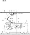
- FIG 1 has a road vehicle 1 according to the invention, for example a heavy commercial vehicle or a bus, an electric or hybrid-electric traction drive 2 and a current collector 3 according to the invention for feeding in traction energy from a two-pole catenary system installed on the road.
- the overhead line system includes a contact wire 4 for each contact pole, one of which serves as a forward conductor and the other as a return conductor.
- the contact wires 4 run approximately parallel to one another and symmetrically to a lane center above an electrified lane 5 of a single-lane or multi-lane lane, such as a freeway.
- the contact wire height Y above the roadway level Y0 is dependent on the location X along lane 5, for example due to a catenary sag between support points.
- the current collector 3 comprises an erectable support frame 6, which is designed, for example, like a pantograph. For this purpose it has a lower support arm 7 and an upper support arm 8 which are connected by a knee joint 9 .
- the support frame 6 is supported via a base joint 10 on the road vehicle 1, for example on its vehicle roof 11 or on a separate structure at roof height.
- the support frame 6 carries a rocker arrangement 12 which is connected in an articulated manner to the upper support arm 8 via a rocker joint 13 .
- the rocker arrangement 12 has a rocker for each contact pole.
- Each rocker is carried by one of two upper support arms 8 and has at least one contact strip 14 aligned transversely to the longitudinal axis of the vehicle.
- Each rocker preferably has two contact strips 14 arranged parallel to one another and one behind the other with respect to the longitudinal axis of the vehicle.
- Each contact strip 14 preferably consists of a piece of carbon carried by a holder.
- Base joint 10, knee joint 9 and rocker joints 13 have joint axes aligned transversely to the longitudinal direction of the vehicle, in order to enable the support frame 6 to raise or lower its support arms 7, 8 in a pantograph-like manner.
- the pantograph 3 includes a lifting device 15, by means of which the contact strips 14 from a lower rest position according to FIG 2 to an upper contact position according to 3 are withdrawable.
- the support frame 6 In the rest position, the support frame 6 is placed on the vehicle roof 11, for example when the road vehicle is driving or parking on non-electrified roadway sections.
- the support frame 6 In the contact position, the support frame 6 is erected so that the contact strips 14 grind the contact wires 4 in an electrically contacting manner and electrical energy from the overhead line system can be fed to the traction drive 2 or an on-board energy store while driving.
- the lifting device 15 includes a pneumatic lifting drive 16, which is designed as an air bellows and is fed by a supply air flow from a compressed air source 17, for example a compressor. In the contact position, the lifting device 15 presses the contact strips 14 with a definable contact force against the contact wires 4.
- the lifting speed V with which the lifting device 15 raises the contact strips 14 vertically, can be controlled.
- the lifting speed V of the contact strips 14 is reduced when they reach, ie close to the contact position, in order to avoid the contact strips 14 hitting the contact wires 4 hard. In this way, impact-related spalling or eruptions of carbon pieces from the contact strips 14 can be prevented or at least reduced.
- the reduction in wear enables the contact strips 14 to have a longer service life and thereby reduces the operating costs of the current collector 3 according to the invention becomes.
- the Stroke phase of the contact strips 14 continues according to FIG 4 consists of a rapid lifting phase, in which the contact strips 14 are lifted from their rest position at a high lifting speed V, and a subsequent contacting phase, in which the contact strips 14 are braked from an adjustable height difference threshold YDS (cf. 3 ) and brought into contact with the contact wires 4 at a reduced lifting speed V.
- a rapid lifting phase in which the contact strips 14 are lifted from their rest position at a high lifting speed V
- a subsequent contacting phase in which the contact strips 14 are braked from an adjustable height difference threshold YDS (cf. 3 ) and brought into contact with the contact wires 4 at a reduced lifting speed V.
- the determination device 19 for determining the height difference YD can have a sensor unit 20 for directly measuring the height difference YD, which can be designed as a laser or radar or magnetic field sensor and can be attached to the rocker arrangement 12 or the vehicle roof 11 .
- the determination device 19 can be connected to a database 21 in which the contact wire heights Y of the overhead contact line system are stored as a function of the location X.
- the determination device 19 also has a locating unit 22 embodied as a GPS receiver, for example, for determining the current vehicle position X and a position sensor 23 for determining the current contact strip height YS above the roadway level Y0.
- the position sensor 23 can be, for example, an internal height sensor or a rotation angle sensor, which takes into account the height of its installation location in the road vehicle 1 above road level Y0 in the measurement result.
- the height difference YD can be calculated from the contact wire height Y0 and the contact strip height YS.
- the database 21 is carried in the road vehicle 1, but can also be arranged on the land side in an operator control center of the catenary system and be connected to the processing unit 24 via a wireless communication link.
- the lifting speed V is braked according to the invention.
- a compressed air source 17 and lifting drive 16 switched pneumatic valve 25 is controlled in order to throttle the supply air flow in the lifting drive 16.
- the current collector 3 can have a braking device 26 which delays the erection of the support frame 6 once the height difference threshold YDS has been reached.
- the braking device 26 can, for example, be coupled to the base joint 10 of the support frame 6 in such a way that, once the height difference threshold YDS is reached, it transmits a braking torque counteracting a righting moment of the lifting device 15 to the support frame 6 .
- Electrical, pneumatic, hydraulic or magnetic braking devices 26 can be used here.
- the braking device 26 can be coupled to a support arm 7 of the support frame 6 in such a way that, once the height difference threshold YDS is reached, it transmits a braking force counteracting a righting force of the lifting device 15 to the support arm 7 .
- the braking device 26 is deactivated when the contact strips 14 contact the contact wires 4, so that the contact forces between contact strips 14 and contact wires 4 are not influenced during regular wired operation of the pantograph 3.
Landscapes
- Engineering & Computer Science (AREA)
- Power Engineering (AREA)
- Transportation (AREA)
- Mechanical Engineering (AREA)
- Physics & Mathematics (AREA)
- Fluid Mechanics (AREA)
- Current-Collector Devices For Electrically Propelled Vehicles (AREA)
Applications Claiming Priority (1)
| Application Number | Priority Date | Filing Date | Title |
|---|---|---|---|
| DE102021203046.7A DE102021203046A1 (de) | 2021-03-26 | 2021-03-26 | Stromabnehmer sowie ein Straßenfahrzeug mit einem solchen Stromabnehmer |
Publications (1)
| Publication Number | Publication Date |
|---|---|
| EP4063171A1 true EP4063171A1 (fr) | 2022-09-28 |
Family
ID=80787244
Family Applications (1)
| Application Number | Title | Priority Date | Filing Date |
|---|---|---|---|
| EP22162747.4A Pending EP4063171A1 (fr) | 2021-03-26 | 2022-03-17 | Collecteur de courant, ainsi que véhicule routier doté d'un tel collecteur de courant |
Country Status (2)
| Country | Link |
|---|---|
| EP (1) | EP4063171A1 (fr) |
| DE (1) | DE102021203046A1 (fr) |
Cited By (2)
| Publication number | Priority date | Publication date | Assignee | Title |
|---|---|---|---|---|
| WO2026013074A1 (fr) * | 2024-07-08 | 2026-01-15 | DETO Holding GmbH | Système collecteur de courant pour prélever un courant dans une ligne conductrice |
| WO2026013069A1 (fr) * | 2024-07-08 | 2026-01-15 | DETO Holding GmbH | Unité de collecteur de courant avec système de capteur |
Families Citing this family (2)
| Publication number | Priority date | Publication date | Assignee | Title |
|---|---|---|---|---|
| DE102021207709A1 (de) | 2021-07-20 | 2023-01-26 | Siemens Mobility GmbH | Stromabnehmer für ein elektrisch oder hybridelektrisch angetriebenes Straßenfahrzeug |
| US20250353377A1 (en) * | 2024-05-16 | 2025-11-20 | Komatsu America Corp. | Vehicle Having Pantograph End Adaptor and an Auto-Steering Guidance System |
Citations (10)
| Publication number | Priority date | Publication date | Assignee | Title |
|---|---|---|---|---|
| DE2438874A1 (de) * | 1974-08-13 | 1976-02-26 | Wilhelm Buchberger | Senkfederantrieb fuer stromabnehmer |
| FR2660257A1 (fr) * | 1990-03-28 | 1991-10-04 | Faiveley Transport | Procede pour commander le deplacement d'un pantographe pour motrices ferroviaires et pantographe appliquant le procede. |
| DE10118608A1 (de) * | 2001-04-12 | 2002-11-07 | Schunk Bahntechnik Gmbh Berghe | Verfahren und Anordnung zur Steuerung einer Anpresskraft eines an einem Fahrdraht anliegenden Stromabnehmers eines Fahrzeuges wie Schienenfahrzeuges |
| DE102012205276A1 (de) * | 2012-03-30 | 2013-10-02 | Siemens Aktiengesellschaft | Nicht schienengebundenes Fahrzeug |
| DE102012105687A1 (de) * | 2012-06-28 | 2014-01-02 | Viseon Bus Gmbh | Verfahren zur induktiven Energieerzeugung für ein Fahrzeug sowie Vorrichtung zur induktiven Energieerzeugung für ein Fahrzeug |
| DE102014111262A1 (de) * | 2014-08-07 | 2016-02-11 | Kummler + Matter Ag | Stromabnehmervorrichtung, Verfahren zum Bewegen einer Stromabnehmervorrichtung sowie Verwendung einer Stromabnehmervorrichtung |
| DE102015211554A1 (de) * | 2015-06-23 | 2016-12-29 | Siemens Aktiengesellschaft | Transportsystem |
| DE102016223051A1 (de) * | 2016-11-22 | 2018-05-24 | Schunk Bahn- Und Industrietechnik Gmbh | Positioniereinheit und Verfahren zur Kontaktierung |
| WO2020043523A1 (fr) * | 2018-08-31 | 2020-03-05 | Siemens Mobility GmbH | Collecteur de courant pour véhicule tracteur électrique non ferroviaire, véhicule tracteur muni d'un tel collecteur de courant, et procédé permettant de faire fonctionner un tel collecteur de courant |
| DE102018215593A1 (de) | 2018-09-13 | 2020-03-19 | Siemens Mobility GmbH | Stromabnehmer für ein nicht spurgebundenes, elektrisch angetriebenes Fahrzeug |
-
2021
- 2021-03-26 DE DE102021203046.7A patent/DE102021203046A1/de not_active Withdrawn
-
2022
- 2022-03-17 EP EP22162747.4A patent/EP4063171A1/fr active Pending
Patent Citations (10)
| Publication number | Priority date | Publication date | Assignee | Title |
|---|---|---|---|---|
| DE2438874A1 (de) * | 1974-08-13 | 1976-02-26 | Wilhelm Buchberger | Senkfederantrieb fuer stromabnehmer |
| FR2660257A1 (fr) * | 1990-03-28 | 1991-10-04 | Faiveley Transport | Procede pour commander le deplacement d'un pantographe pour motrices ferroviaires et pantographe appliquant le procede. |
| DE10118608A1 (de) * | 2001-04-12 | 2002-11-07 | Schunk Bahntechnik Gmbh Berghe | Verfahren und Anordnung zur Steuerung einer Anpresskraft eines an einem Fahrdraht anliegenden Stromabnehmers eines Fahrzeuges wie Schienenfahrzeuges |
| DE102012205276A1 (de) * | 2012-03-30 | 2013-10-02 | Siemens Aktiengesellschaft | Nicht schienengebundenes Fahrzeug |
| DE102012105687A1 (de) * | 2012-06-28 | 2014-01-02 | Viseon Bus Gmbh | Verfahren zur induktiven Energieerzeugung für ein Fahrzeug sowie Vorrichtung zur induktiven Energieerzeugung für ein Fahrzeug |
| DE102014111262A1 (de) * | 2014-08-07 | 2016-02-11 | Kummler + Matter Ag | Stromabnehmervorrichtung, Verfahren zum Bewegen einer Stromabnehmervorrichtung sowie Verwendung einer Stromabnehmervorrichtung |
| DE102015211554A1 (de) * | 2015-06-23 | 2016-12-29 | Siemens Aktiengesellschaft | Transportsystem |
| DE102016223051A1 (de) * | 2016-11-22 | 2018-05-24 | Schunk Bahn- Und Industrietechnik Gmbh | Positioniereinheit und Verfahren zur Kontaktierung |
| WO2020043523A1 (fr) * | 2018-08-31 | 2020-03-05 | Siemens Mobility GmbH | Collecteur de courant pour véhicule tracteur électrique non ferroviaire, véhicule tracteur muni d'un tel collecteur de courant, et procédé permettant de faire fonctionner un tel collecteur de courant |
| DE102018215593A1 (de) | 2018-09-13 | 2020-03-19 | Siemens Mobility GmbH | Stromabnehmer für ein nicht spurgebundenes, elektrisch angetriebenes Fahrzeug |
Cited By (2)
| Publication number | Priority date | Publication date | Assignee | Title |
|---|---|---|---|---|
| WO2026013074A1 (fr) * | 2024-07-08 | 2026-01-15 | DETO Holding GmbH | Système collecteur de courant pour prélever un courant dans une ligne conductrice |
| WO2026013069A1 (fr) * | 2024-07-08 | 2026-01-15 | DETO Holding GmbH | Unité de collecteur de courant avec système de capteur |
Also Published As
| Publication number | Publication date |
|---|---|
| DE102021203046A1 (de) | 2022-09-29 |
Similar Documents
| Publication | Publication Date | Title |
|---|---|---|
| EP2714457B1 (fr) | Véhicule non ferroviaire | |
| EP2701940B1 (fr) | Véhicule non ferroviaire | |
| DE102021203046A1 (de) | Stromabnehmer sowie ein Straßenfahrzeug mit einem solchen Stromabnehmer | |
| EP2917064B1 (fr) | Véhicule non ferroviaire | |
| EP0189955B1 (fr) | Véhicule souterrain sans rails articulé avec entraînement par moteur électrique | |
| DE102012213460A1 (de) | Nicht schienengebundenes Fahrzeug | |
| WO2012163762A2 (fr) | Véhicule non ferroviaire | |
| EP3974234B1 (fr) | Véhicule routier doté d'un collecteur de courant | |
| EP3266638A1 (fr) | Commande automatisée d'une voie de circulation théorique destinée à l'alimentation continue en énergie électrique | |
| EP3544843A1 (fr) | Unité de positionnement et procédé de mise en contact électrique | |
| EP3031658A1 (fr) | Procédé de chargement d'un accumulateur d'énergie pour un véhicule | |
| EP3790759A1 (fr) | Collecteur de courant pour véhicule tracteur électrique non ferroviaire, véhicule tracteur muni d'un tel collecteur de courant, et procédé permettant de faire fonctionner un tel collecteur de courant | |
| EP3109086A1 (fr) | Systeme de transport | |
| DE102012217720A1 (de) | Nicht schienengebundenes Fahrzeug | |
| DE102021207821A1 (de) | Stromabnehmer für ein elektrisch oder hybridelektrisch angetriebenes Straßenfahrzeug | |
| EP3269582A1 (fr) | Véhicule à propulsion électrique ou hybride ne roulant pas sur rails | |
| EP4032740A1 (fr) | Agencement de collecteur de courant pour fils de contact à double pôle | |
| DE102012006405A1 (de) | Fahrzeug mit einem Stromabnehmer | |
| DE102015213071A1 (de) | Infrastrukturgestützte Detektion von Fahrleitungen | |
| DE102013213788A1 (de) | Vorrichtung zur Ermittlung einer Kontaktkraft und nicht schienengebundenes Fahrzeug mit einer solchen Vorrichtung | |
| DE10012039C2 (de) | Fahrdraht- und Stromabnehmersystem für Elektrobusse | |
| EP3715168B1 (fr) | Agencement de collecteur de courant pour fils de contact à double pôle | |
| DE102023206226A1 (de) | Stromabnehmer und ein mit einem solchen ausgestattetes Straßenfahrzeug | |
| WO2011110620A2 (fr) | Ensemble de transfert d'énergie inductive à des véhicules routiers électriques | |
| DE102022208517A1 (de) | Straßenfahrzeug mit Stromabnehmer |
Legal Events
| Date | Code | Title | Description |
|---|---|---|---|
| PUAI | Public reference made under article 153(3) epc to a published international application that has entered the european phase |
Free format text: ORIGINAL CODE: 0009012 |
|
| STAA | Information on the status of an ep patent application or granted ep patent |
Free format text: STATUS: THE APPLICATION HAS BEEN PUBLISHED |
|
| AK | Designated contracting states |
Kind code of ref document: A1 Designated state(s): AL AT BE BG CH CY CZ DE DK EE ES FI FR GB GR HR HU IE IS IT LI LT LU LV MC MK MT NL NO PL PT RO RS SE SI SK SM TR |
|
| STAA | Information on the status of an ep patent application or granted ep patent |
Free format text: STATUS: REQUEST FOR EXAMINATION WAS MADE |
|
| 17P | Request for examination filed |
Effective date: 20230320 |
|
| RBV | Designated contracting states (corrected) |
Designated state(s): AL AT BE BG CH CY CZ DE DK EE ES FI FR GB GR HR HU IE IS IT LI LT LU LV MC MK MT NL NO PL PT RO RS SE SI SK SM TR |
|
| STAA | Information on the status of an ep patent application or granted ep patent |
Free format text: STATUS: EXAMINATION IS IN PROGRESS |
|
| 17Q | First examination report despatched |
Effective date: 20240301 |
|
| RAP3 | Party data changed (applicant data changed or rights of an application transferred) |
Owner name: SIEMENS MOBILITY GMBH |