EP4063185B1 - Pince de suspension pour maintenir un profil conducteur, système de caténaire aérienne rigide et voie ferrée comprenant une telle pince de suspension - Google Patents
Pince de suspension pour maintenir un profil conducteur, système de caténaire aérienne rigide et voie ferrée comprenant une telle pince de suspension Download PDFInfo
- Publication number
- EP4063185B1 EP4063185B1 EP21315051.9A EP21315051A EP4063185B1 EP 4063185 B1 EP4063185 B1 EP 4063185B1 EP 21315051 A EP21315051 A EP 21315051A EP 4063185 B1 EP4063185 B1 EP 4063185B1
- Authority
- EP
- European Patent Office
- Prior art keywords
- hanger clamp
- hanger
- base plate
- railtrack
- conductive
- Prior art date
- Legal status (The legal status is an assumption and is not a legal conclusion. Google has not performed a legal analysis and makes no representation as to the accuracy of the status listed.)
- Active
Links
Images

Classifications
-
- B—PERFORMING OPERATIONS; TRANSPORTING
- B60—VEHICLES IN GENERAL
- B60M—POWER SUPPLY LINES, AND DEVICES ALONG RAILS, FOR ELECTRICALLY- PROPELLED VEHICLES
- B60M1/00—Power supply lines for contact with collector on vehicle
- B60M1/30—Power rails
- B60M1/307—Supports
-
- B—PERFORMING OPERATIONS; TRANSPORTING
- B60—VEHICLES IN GENERAL
- B60M—POWER SUPPLY LINES, AND DEVICES ALONG RAILS, FOR ELECTRICALLY- PROPELLED VEHICLES
- B60M1/00—Power supply lines for contact with collector on vehicle
- B60M1/12—Trolley lines; Accessories therefor
- B60M1/20—Arrangements for supporting or suspending trolley wires, e.g. from buildings
- B60M1/24—Clamps; Splicers; Anchor tips
-
- B—PERFORMING OPERATIONS; TRANSPORTING
- B60—VEHICLES IN GENERAL
- B60M—POWER SUPPLY LINES, AND DEVICES ALONG RAILS, FOR ELECTRICALLY- PROPELLED VEHICLES
- B60M1/00—Power supply lines for contact with collector on vehicle
- B60M1/30—Power rails
- B60M1/302—Power rails composite
Definitions
- the present invention relates to a hanger clamp for holding a conductive profile, to a rigid overhead catenary system and to a railtrack comprising such a hanger clamp.
- CMOS complementary metal-oxide-semiconductor
- a ROCS comprises a contact wire, usually made out of copper or one of its alloys, that is rigidly held by a conductive profile, also called busbar.
- Common busbars are made out of lightweight conductive metal, such as aluminum or one of its alloys. To ensure a good geometric alignment of the contact wire relatively to the rail track, each busbar holds the contact wire continuously and is held by hanger clamps.
- the hanger clamps are fixed to the infrastructure of the railtrack, for example to a ceiling of a tunnel section or to a steel cantilever linked to the trackside, so that the contact wire is hanging downwardly, the contact wire being arranged along a longitudinal direction parallel to the railtrack.
- the busbar and the hanger clamp are electrically connected together, to ensure that the same electric potential is present on the hanger clamp and on the busbar.
- the busbars are continuous and made from metal, the busbars show relatively high dimensional variations due to the temperature changes, caused for example by seasonal variations or by self-heating when an electric current flows through the ROCS.
- the busbar held by the hanger clamps is allowed to slide relatively to the hanger clamps along the longitudinal direction.
- CN-202782747-U describes, for example, a hanger clamp that comprises inserts made from carbon/graphite composite materials. Such inserts are costly to produce and remain relatively brittle, requiring regular maintenance.
- the document CN 102 785 590 B describes also a similar hanger clamp.
- the document KR 2017 0043437 A describes a hanger clamp with a plastic material with a small frictional resistance, but with insulating characteristics.
- aspects of the invention pertains to a hanger clamp for holding a conductive profile of a rigid overhead catenary system belonging to a railtrack, the hanger clamp comprising:
- the inserts are made from a material comprising a synthetic polymer and a conductive charge.
- the inserts are both cheap to produce and resilient, thus improving the cost price and the durability of the hanger clamp.
- the conductive charge thanks to the conductive charge, the busbar held by the hanger clamp and the hanger clamp present the same electrical potential, which reduces the risk of electrical arc, while the synthetic polymer allows sliding of the busbar relatively to the hanger clamp in the longitudinal direction.
- such a hanger clamp may incorporate one or more of the following features, considered alone or according to any combination according to the appended claims.
- the invention also concerns rigid overhead catenary system, comprising a contact line held by a conductive profile, the conductive profile being held by hanger clamps, wherein at least one hanger clamp is as described here above.
- a railtrack comprising a track and a rigid overhead catenary system as described here above.
- Figure 1 represents a railtrack 2.
- the railtrack 2 comprises two rails, which are parallel to each other. Only one rail 20 is visible on figure 1 , and is supposed to be straight and horizontal.
- the railtrack 2 is configured to have a vehicle 4 running on the rails 20.
- the vehicle 4 is for example a rail electric vehicle, such as a train, a metro, or a tramway, and comprises wheels 40 that are powered by an electric motor.
- the electric motor is not shown.
- the vehicle 3 runs on tires, and the rails 20 are replaced by guideways.
- the railtrack 2 comprises a rigid overhead catenary system 100, also called ROCS 100 within the present description, configured to supply the vehicle 4 with electric energy.
- ROCS 100 rigid overhead catenary system 100
- the vehicle 4 comprises an electricity collection device 42, such as a pantograph, which comes into contact with the ROCS 100 to collect electrical energy.
- the electricity returns to the railtrack 2 through the wheels 40.
- the ROCS 100 is fixed relative to the rails 20, more precisely the ROCS is arranged above the rail 20 at a fixed height, so that the electricity collection device 42 works properly when the rail vehicle 4 moves.
- the ROCS 100 comprises a contact wire 110 and a busbar 120.
- the contact wire 110 is configured to be in contact with the electricity collection device 42 and is made from conductive metal, preferably from copper or copper alloy, to ensure a low electric resistance.
- the wire 110 forms a contact line for the ROCS 100.
- the contact wire 110 presents a cylindrical shape extending along a longitudinal axis A110, which is parallel to the rail 20.
- the contact wire 110 is held by the busbar 120, preferably continuously and rigidly held, so that the contact wire 110 does not flex when the current collection device 42 is pressing onto the contact wire 110.
- the busbar 120 is a conductive profile, which extends along a longitudinal axis A120, parallel to the longitudinal axis A110 of the wire 110.
- the busbar 120 is preferably made from a lightweight and conductive metal such as aluminum or an aluminum alloy.
- the busbar 120 is usually produced by extrusion.
- the ROCS 100 further comprises hanger clamps 200, which are for example fixed to a ceiling 22 of a tunnel section of the railtrack 2, above the rail 20. In other words, the ROCS 100 is suspended to the ceiling 22.
- the busbar 120 extends downwardly from the clamps 200, and the contact wire 110, held by the busbar 120, faces the ground.
- the ROCS 100 is attached to a beam belonging to a mast, the mast being arranged on the trackside and the beam extending above the rail 20.
- the longitudinal axis A120 is horizontal, and that the busbar 120 hangs vertically.
- the actual orientation of the busbar 120 may vary, for example in slope sections or in curve sections of the railtrack 2.
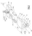
- the ROCS 100 is further detailed with reference to figure 2 .
- the contact wire 110 presents a globally round profile, with two slits 112 configured to cooperate with clamping tips of the busbar 120, as described later.
- the busbar 120 comprises a base plate 122, which is configured to cooperate with the hanger clamps 120.
- the base plate 122 has flat and elongated shape, that extends along a median plane P122 and that is arranged along the longitudinal axis A120 of the busbar 120.
- the medial plane P122 is supposed to be horizontal.
- the base plate 122 comprises two side edges 122A and 122B, which are parallel to a longitudinal plane P120, which is orthogonal to the median plane P122 and parallel to the longitudinal axis A120.
- the busbar 120 further comprises two holding arms 124.
- the holding arms 124 extend from the base plate 122 on the same side of the median plan P122, here from a downward side of the base 122.
- Each holding arm 124 comprises a main portion 126 and a clamping portion 128.
- the main portions 126 are parallel to the longitudinal plane P120.
- the two clamping portion 128 converge toward each other and comprise each a clamping tip 130, which cooperate with a respective slit 112 of the contact wire 110.
- the hanger clamp 200 comprises a connecting portion 210 and a clamping portion 220. Only a threaded portion 212 and a nut 214 of the connecting portion 210 are represented on figure 2 .
- the connecting portion 210 is configured to cooperate with an element of the railtrack 2, such as a beam or a tunnel ceiling, etc., in order to connect the clamping portion 220 to the railtrack 2, in particular in order to adjust the height of the clamping portion 220 above the railtrack 2.
- an element of the railtrack 2 such as a beam or a tunnel ceiling, etc.
- the clamping portion 220 is made of metallic lightweight material such as an aluminum alloy.
- the clamping portion 220 is configured to receive the base plate 122 of the busbar 120. In other words, the clamping portion 220 is configured to connect said base plate 122 to a fixed element of the railtrack 2.
- the clamping portion 220 When the base plate 122 is received in the clamping portion 220, the clamping portion 220 extends along a plane that is aligned with the median plane P122, and the clamping portion 220 has a cylindrical shape, with a rectangular cross section, extending along an axis that is parallel to the longitudinal axis A120.
- the clamping portion 220 comprises two jaws 222.
- the two jaws 222 have preferably the same shape and are reversibly assembled to each other with fixing organs 224, such as nuts and bolts.
- the two jaws 222 are arranged symmetrically from each other apart the longitudinal plane P120.
- Each jaw 222 has a cylindrical shape with a "U” profile extending along the longitudinal axis A120, the jaws 222 facing each other with the opening of the "U” being oriented toward the longitudinal plane P120.
- Each jaw 222 defines a reception volume V222, configured to receive a respective side edge 122A or 1228 of the base plate 122.
- the hanger clamp 200 further comprises two inserts 230, each insert 230 being received within the reception volume V222 of a respective jaw 222.
- each insert 230 has a cylindrical shape with a "U" profile extending along the longitudinal axis A120 in the mounted configuration of the hanger clamp 200.
- the inserts 230 are sandwiched between the base plate 122 and the jaws 222, so that the base plate 122 does not contact directly the jaws 222.
- the inserts 230 are in contact with the base plate 122 without pressing on the surface of the base plate 122, so that translation movements of the base plate 122 relative to the hanger clamp 200 along any direction radial to the longitudinal axis A120 are prevented, while translation movements the base plate 122 relative to the hanger clamp 200 along the longitudinal axis A120 are allowed.
- the base plate 122 is just leaning on the inserts 230 without additional forces except the busbar 120 own weight.
- an air gap is arranged between the inserts 230 and the surface of the base plate 122. The air gap allows the free sliding of the busbar 120 relative to the clamping portion 220, and also the free orientation of the busbar 120 when the busbar 120 is curved, for example to follow curved tracks and for staggering.
- Each insert 230 is received within a respective reception volume V222 and is configured to be positioned between the corresponding jaw 222 and the base plate 122, while allowing sliding movements of the busbar 120 relative to the hanger clamp 200 along the longitudinal axis A120.
- the inserts 230 are mare from a material comprising synthetic polymer, that is selected for a low friction coefficient and high wear resistance, so that when the inserts 230 is in contact with a surface of the base plate 122, sliding movements of the busbar 120 relative to the hanger clamp 200 along the longitudinal axis A120 are allowed.
- Each insert 230 is also configured to conduct electricity between the base plate 122 and the clamping portion 220.
- Synthetic polymers used in railroad applications are usually electrically insulating.
- the material of the inserts 230 comprises a conductive charge, so that the material of the inserts 230 is conductive enough so the clamping portion 220 and the busbar 120 have the same electric potential.
- a charge in the field of polymers, a charge is a mass of material, usually in the shape of fine powder or fibers, that is dispersed in a polymer material to reduce the cost and/or to adjust the properties of said polymer material, for example to adjust mechanical properties, density, thermal resistance, etc.
- the material of the inserts 230 has an electrical resistance lower than 10 k ⁇ - kilo-ohms -, preferably lower than 1.5 kQ. in other words, the inserts 230 are configured to conduct electricity between the base plate 122 and the clamping portion 220.
- the conductive charge is preferably in the shape of fiber, to contribute also to the strength of the material of the inserts 230. More preferably, the conductive charge comprises carbon fibers, which are electrically conductive and contribute to improve the tensile strength of the polymer material.
- the polymer material of the inserts 230 is preferably a thermoplastic polymer. Compared to other types of polymers, such as thermosetting polymers, thermoplastic polymers show a better mechanical behavior in terms of wear resistance, toughness or thermal resistance.
- thermoplastic polymer for the material of the inserts 230 is polyamide.
- Raw materials comprising polyamide with carbon fibers added as a charge are, for example, commercially available from LATI Company under the brand name "LatiOhm”.
Landscapes
- Engineering & Computer Science (AREA)
- Mechanical Engineering (AREA)
- Current-Collector Devices For Electrically Propelled Vehicles (AREA)
- Clamps And Clips (AREA)
Claims (7)
- Pince de suspension (200) pour maintenir un profilé conducteur (120) d'un système de caténaire aérienne rigide (100) appartenant à une voie ferrée (2), la pince de suspension (200) comprenant :- une partie de serrage (220), de préférence en alliage d'aluminium, configurée pour recevoir une plaque de base (122) du profilé conducteur (120), la partie de serrage (220) s'étendant le long d'un plan médian (P122) et le long d'un axe longitudinal (A120), qui est parallèle au plan médian,- une partie de connexion (210), configurée pour connecter ladite plaque de base (122) à un élément fixe de la voie ferrée (2), tel qu'une poutre ou un plafond de tunnel (22),dans laquelle la partie de serrage (220) comprend deux mâchoires (222), chaque mâchoire (222) ayant un profil en U s'étendant le long de l'axe longitudinal (A120) et faisant face à l'autre, chaque mâchoire définissant un volume de réception (V222) configuré pour recevoir un bord (122A, 122B) respectif de la plaque de base (122),dans laquelle la pince de suspension (200) comprend en outre deux inserts (230), chaque insert étant reçu dans un volume de réception (V222) respectif et étant configuré pour être positionné entre la mâchoire correspondante et la plaque de base tout en permettant des mouvements de coulissement du profilé conducteur (120) par rapport à la pince de suspension (200) le long de l'axe longitudinal, chaque insert étant également configuré pour conduire l'électricité entre la plaque de base (122) et la partie de serrage (220),caractérisée en ce que les inserts (230) sont fabriqués à partir d'un matériau comprenant un polymère synthétique et une charge conductrice.
- Pince de suspension (200) selon la revendication 1, dans laquelle les mâchoires (222) sont agencées symétriquement les unes par rapport aux autres selon un plan longitudinal (P120), le plan longitudinal étant parallèle à l'axe longitudinal (A120) et orthogonal au plan médian (P122).
- Pince de suspension (200) selon la revendication 1 ou 2, dans laquelle le polymère synthétique est un polymère thermoplastique.
- Pince de suspension (200) selon l'une quelconque des revendications 1 à 3, dans laquelle la charge conductrice comprend des fibres.
- Pince de suspension (200) selon l'une quelconque des revendications 1 à 4, dans laquelle les inserts sont fabriqués en polyamide avec des fibres de carbone.
- Système de caténaire aérienne rigide (100), comprenant une ligne de contact (110) maintenue par un profilé conducteur (120), le profilé conducteur (120) étant maintenu par des pinces de suspension (200), dans lequel au moins une des pinces de suspension (200) est conforme à l'une quelconque des revendications précédentes.
- Voie ferrée (2), comprenant une voie (20) et un système de caténaire aérienne rigide (100) conforme à la revendication précédente.
Priority Applications (2)
| Application Number | Priority Date | Filing Date | Title |
|---|---|---|---|
| ES21315051T ES3012391T3 (en) | 2021-03-24 | 2021-03-24 | Hanger clamp for holding a conductive profile, rigid overhead catenary system and railtrack comprising such a hanger clamp |
| EP21315051.9A EP4063185B1 (fr) | 2021-03-24 | 2021-03-24 | Pince de suspension pour maintenir un profil conducteur, système de caténaire aérienne rigide et voie ferrée comprenant une telle pince de suspension |
Applications Claiming Priority (1)
| Application Number | Priority Date | Filing Date | Title |
|---|---|---|---|
| EP21315051.9A EP4063185B1 (fr) | 2021-03-24 | 2021-03-24 | Pince de suspension pour maintenir un profil conducteur, système de caténaire aérienne rigide et voie ferrée comprenant une telle pince de suspension |
Publications (2)
| Publication Number | Publication Date |
|---|---|
| EP4063185A1 EP4063185A1 (fr) | 2022-09-28 |
| EP4063185B1 true EP4063185B1 (fr) | 2024-11-13 |
Family
ID=75639847
Family Applications (1)
| Application Number | Title | Priority Date | Filing Date |
|---|---|---|---|
| EP21315051.9A Active EP4063185B1 (fr) | 2021-03-24 | 2021-03-24 | Pince de suspension pour maintenir un profil conducteur, système de caténaire aérienne rigide et voie ferrée comprenant une telle pince de suspension |
Country Status (2)
| Country | Link |
|---|---|
| EP (1) | EP4063185B1 (fr) |
| ES (1) | ES3012391T3 (fr) |
Family Cites Families (5)
| Publication number | Priority date | Publication date | Assignee | Title |
|---|---|---|---|---|
| DE102010033451A1 (de) * | 2010-08-05 | 2012-02-09 | Furrer + Frey Ag | Stromschienenanordnung |
| CN102785590B (zh) * | 2012-08-28 | 2015-01-28 | 浙江旺隆轨道交通设备有限公司 | 一种无螺栓汇流排弹性线夹 |
| CN202782747U (zh) | 2012-08-28 | 2013-03-13 | 浙江旺隆轨道交通设备有限公司 | 一种无螺栓汇流排弹性线夹 |
| DE102014001456B4 (de) * | 2014-02-05 | 2017-12-21 | Rail Power Systems Gmbh | Befestigungsvorrichtung für eine Stromschiene und Fahrleitungssystem |
| KR102576806B1 (ko) * | 2015-10-13 | 2023-09-11 | 엘에스전선 주식회사 | 신축이음장치 |
-
2021
- 2021-03-24 EP EP21315051.9A patent/EP4063185B1/fr active Active
- 2021-03-24 ES ES21315051T patent/ES3012391T3/es active Active
Also Published As
| Publication number | Publication date |
|---|---|
| EP4063185A1 (fr) | 2022-09-28 |
| ES3012391T3 (en) | 2025-04-09 |
Similar Documents
| Publication | Publication Date | Title |
|---|---|---|
| KR101902361B1 (ko) | 강체 전차 선로용 절연구분장치 | |
| CN102317104A (zh) | 一种导电轨接头 | |
| KR101746285B1 (ko) | 강체전차선용 지지클램프 | |
| KR200497341Y1 (ko) | 강체전차선용 지지클램프 | |
| EP4063185B1 (fr) | Pince de suspension pour maintenir un profil conducteur, système de caténaire aérienne rigide et voie ferrée comprenant une telle pince de suspension | |
| CN115742884B (zh) | 基于弹簧和阻尼电刷的刚性悬挂接触网系统 | |
| US9845025B2 (en) | Rigid T-rail conductor system | |
| EP4194260B1 (fr) | Barre omnibus pour maintenir un fil de contact, système de caténaire aérienne rigide et système comprenant une telle barre omnibus | |
| US4250982A (en) | Section insulator for catenary systems | |
| US4187934A (en) | Section insulator for catenary systems | |
| KR101910230B1 (ko) | 강체전차선 연결구조 | |
| KR20130087778A (ko) | 신축이음장치 | |
| EP0000980A1 (fr) | Contacteur collecteur de courant en charbon et dispositif pantographe | |
| US5676224A (en) | Electrical collector shoe assembly | |
| US1336503A (en) | Catenary suspension system for electric railways | |
| US4363939A (en) | Electrical supply line for the supply or current to railway vehicles | |
| KR101264312B1 (ko) | 1열 구조로 구성된 교류/직류 구분용 절연구분장치 | |
| EP3922508B1 (fr) | Ensemble support isolant pour une caténaire adaptée à l'alimentation d'un véhicule électrique, notamment d'un tramway ou d'un trolleybus et caténaire associée | |
| KR101269230B1 (ko) | 철도차량용 도전레일설비 | |
| US1055782A (en) | Overhead-line structure for electric railways. | |
| KR20170039432A (ko) | 강체전차선 | |
| KR101246930B1 (ko) | 경량 전철용 제3 궤조 집전 장치 | |
| RU2296065C1 (ru) | Скользящий зажим воздушной стрелки | |
| US1014071A (en) | Current-collector for electric cranes. | |
| US1157393A (en) | Trolley-conductor. |
Legal Events
| Date | Code | Title | Description |
|---|---|---|---|
| PUAI | Public reference made under article 153(3) epc to a published international application that has entered the european phase |
Free format text: ORIGINAL CODE: 0009012 |
|
| STAA | Information on the status of an ep patent application or granted ep patent |
Free format text: STATUS: THE APPLICATION HAS BEEN PUBLISHED |
|
| STAA | Information on the status of an ep patent application or granted ep patent |
Free format text: STATUS: REQUEST FOR EXAMINATION WAS MADE |
|
| AK | Designated contracting states |
Kind code of ref document: A1 Designated state(s): AL AT BE BG CH CY CZ DE DK EE ES FI FR GB GR HR HU IE IS IT LI LT LU LV MC MK MT NL NO PL PT RO RS SE SI SK SM TR |
|
| 17P | Request for examination filed |
Effective date: 20220906 |
|
| RBV | Designated contracting states (corrected) |
Designated state(s): AL AT BE BG CH CY CZ DE DK EE ES FI FR GB GR HR HU IE IS IT LI LT LU LV MC MK MT NL NO PL PT RO RS SE SI SK SM TR |
|
| P01 | Opt-out of the competence of the unified patent court (upc) registered |
Effective date: 20230823 |
|
| RAP1 | Party data changed (applicant data changed or rights of an application transferred) |
Owner name: ALSTOM HOLDINGS |
|
| GRAP | Despatch of communication of intention to grant a patent |
Free format text: ORIGINAL CODE: EPIDOSNIGR1 |
|
| STAA | Information on the status of an ep patent application or granted ep patent |
Free format text: STATUS: GRANT OF PATENT IS INTENDED |
|
| INTG | Intention to grant announced |
Effective date: 20240621 |
|
| GRAS | Grant fee paid |
Free format text: ORIGINAL CODE: EPIDOSNIGR3 |
|
| GRAA | (expected) grant |
Free format text: ORIGINAL CODE: 0009210 |
|
| STAA | Information on the status of an ep patent application or granted ep patent |
Free format text: STATUS: THE PATENT HAS BEEN GRANTED |
|
| AK | Designated contracting states |
Kind code of ref document: B1 Designated state(s): AL AT BE BG CH CY CZ DE DK EE ES FI FR GB GR HR HU IE IS IT LI LT LU LV MC MK MT NL NO PL PT RO RS SE SI SK SM TR |
|
| REG | Reference to a national code |
Ref country code: GB Ref legal event code: FG4D |
|
| REG | Reference to a national code |
Ref country code: CH Ref legal event code: EP |
|
| REG | Reference to a national code |
Ref country code: IE Ref legal event code: FG4D |
|
| REG | Reference to a national code |
Ref country code: DE Ref legal event code: R096 Ref document number: 602021021742 Country of ref document: DE |
|
| REG | Reference to a national code |
Ref country code: GR Ref legal event code: EP Ref document number: 20250400092 Country of ref document: GR Effective date: 20250211 |
|
| REG | Reference to a national code |
Ref country code: LT Ref legal event code: MG9D |
|
| REG | Reference to a national code |
Ref country code: NL Ref legal event code: MP Effective date: 20241113 |
|
| REG | Reference to a national code |
Ref country code: ES Ref legal event code: FG2A Ref document number: 3012391 Country of ref document: ES Kind code of ref document: T3 Effective date: 20250409 |
|
| PG25 | Lapsed in a contracting state [announced via postgrant information from national office to epo] |
Ref country code: PT Free format text: LAPSE BECAUSE OF FAILURE TO SUBMIT A TRANSLATION OF THE DESCRIPTION OR TO PAY THE FEE WITHIN THE PRESCRIBED TIME-LIMIT Effective date: 20250313 Ref country code: IS Free format text: LAPSE BECAUSE OF FAILURE TO SUBMIT A TRANSLATION OF THE DESCRIPTION OR TO PAY THE FEE WITHIN THE PRESCRIBED TIME-LIMIT Effective date: 20250313 Ref country code: HR Free format text: LAPSE BECAUSE OF FAILURE TO SUBMIT A TRANSLATION OF THE DESCRIPTION OR TO PAY THE FEE WITHIN THE PRESCRIBED TIME-LIMIT Effective date: 20241113 |
|
| PG25 | Lapsed in a contracting state [announced via postgrant information from national office to epo] |
Ref country code: NL Free format text: LAPSE BECAUSE OF FAILURE TO SUBMIT A TRANSLATION OF THE DESCRIPTION OR TO PAY THE FEE WITHIN THE PRESCRIBED TIME-LIMIT Effective date: 20241113 Ref country code: FI Free format text: LAPSE BECAUSE OF FAILURE TO SUBMIT A TRANSLATION OF THE DESCRIPTION OR TO PAY THE FEE WITHIN THE PRESCRIBED TIME-LIMIT Effective date: 20241113 |
|
| REG | Reference to a national code |
Ref country code: AT Ref legal event code: MK05 Ref document number: 1741456 Country of ref document: AT Kind code of ref document: T Effective date: 20241113 |
|
| PG25 | Lapsed in a contracting state [announced via postgrant information from national office to epo] |
Ref country code: BG Free format text: LAPSE BECAUSE OF FAILURE TO SUBMIT A TRANSLATION OF THE DESCRIPTION OR TO PAY THE FEE WITHIN THE PRESCRIBED TIME-LIMIT Effective date: 20241113 |
|
| PG25 | Lapsed in a contracting state [announced via postgrant information from national office to epo] |
Ref country code: LV Free format text: LAPSE BECAUSE OF FAILURE TO SUBMIT A TRANSLATION OF THE DESCRIPTION OR TO PAY THE FEE WITHIN THE PRESCRIBED TIME-LIMIT Effective date: 20241113 Ref country code: AT Free format text: LAPSE BECAUSE OF FAILURE TO SUBMIT A TRANSLATION OF THE DESCRIPTION OR TO PAY THE FEE WITHIN THE PRESCRIBED TIME-LIMIT Effective date: 20241113 |
|
| PG25 | Lapsed in a contracting state [announced via postgrant information from national office to epo] |
Ref country code: PL Free format text: LAPSE BECAUSE OF FAILURE TO SUBMIT A TRANSLATION OF THE DESCRIPTION OR TO PAY THE FEE WITHIN THE PRESCRIBED TIME-LIMIT Effective date: 20241113 |
|
| PG25 | Lapsed in a contracting state [announced via postgrant information from national office to epo] |
Ref country code: RS Free format text: LAPSE BECAUSE OF FAILURE TO SUBMIT A TRANSLATION OF THE DESCRIPTION OR TO PAY THE FEE WITHIN THE PRESCRIBED TIME-LIMIT Effective date: 20250213 |
|
| PG25 | Lapsed in a contracting state [announced via postgrant information from national office to epo] |
Ref country code: SM Free format text: LAPSE BECAUSE OF FAILURE TO SUBMIT A TRANSLATION OF THE DESCRIPTION OR TO PAY THE FEE WITHIN THE PRESCRIBED TIME-LIMIT Effective date: 20241113 |
|
| PG25 | Lapsed in a contracting state [announced via postgrant information from national office to epo] |
Ref country code: DK Free format text: LAPSE BECAUSE OF FAILURE TO SUBMIT A TRANSLATION OF THE DESCRIPTION OR TO PAY THE FEE WITHIN THE PRESCRIBED TIME-LIMIT Effective date: 20241113 |
|
| PGFP | Annual fee paid to national office [announced via postgrant information from national office to epo] |
Ref country code: ES Payment date: 20250429 Year of fee payment: 5 |
|
| PG25 | Lapsed in a contracting state [announced via postgrant information from national office to epo] |
Ref country code: EE Free format text: LAPSE BECAUSE OF FAILURE TO SUBMIT A TRANSLATION OF THE DESCRIPTION OR TO PAY THE FEE WITHIN THE PRESCRIBED TIME-LIMIT Effective date: 20241113 |
|
| PGFP | Annual fee paid to national office [announced via postgrant information from national office to epo] |
Ref country code: CH Payment date: 20250401 Year of fee payment: 5 |
|
| PG25 | Lapsed in a contracting state [announced via postgrant information from national office to epo] |
Ref country code: RO Free format text: LAPSE BECAUSE OF FAILURE TO SUBMIT A TRANSLATION OF THE DESCRIPTION OR TO PAY THE FEE WITHIN THE PRESCRIBED TIME-LIMIT Effective date: 20241113 |
|
| PG25 | Lapsed in a contracting state [announced via postgrant information from national office to epo] |
Ref country code: SK Free format text: LAPSE BECAUSE OF FAILURE TO SUBMIT A TRANSLATION OF THE DESCRIPTION OR TO PAY THE FEE WITHIN THE PRESCRIBED TIME-LIMIT Effective date: 20241113 |
|
| PG25 | Lapsed in a contracting state [announced via postgrant information from national office to epo] |
Ref country code: CZ Free format text: LAPSE BECAUSE OF FAILURE TO SUBMIT A TRANSLATION OF THE DESCRIPTION OR TO PAY THE FEE WITHIN THE PRESCRIBED TIME-LIMIT Effective date: 20241113 |
|
| PG25 | Lapsed in a contracting state [announced via postgrant information from national office to epo] |
Ref country code: IT Free format text: LAPSE BECAUSE OF FAILURE TO SUBMIT A TRANSLATION OF THE DESCRIPTION OR TO PAY THE FEE WITHIN THE PRESCRIBED TIME-LIMIT Effective date: 20241113 |
|
| REG | Reference to a national code |
Ref country code: DE Ref legal event code: R097 Ref document number: 602021021742 Country of ref document: DE |
|
| PG25 | Lapsed in a contracting state [announced via postgrant information from national office to epo] |
Ref country code: SE Free format text: LAPSE BECAUSE OF FAILURE TO SUBMIT A TRANSLATION OF THE DESCRIPTION OR TO PAY THE FEE WITHIN THE PRESCRIBED TIME-LIMIT Effective date: 20241113 |
|
| PLBE | No opposition filed within time limit |
Free format text: ORIGINAL CODE: 0009261 |
|
| STAA | Information on the status of an ep patent application or granted ep patent |
Free format text: STATUS: NO OPPOSITION FILED WITHIN TIME LIMIT |
|
| REG | Reference to a national code |
Ref country code: DE Ref legal event code: R119 Ref document number: 602021021742 Country of ref document: DE |
|
| PG25 | Lapsed in a contracting state [announced via postgrant information from national office to epo] |
Ref country code: MC Free format text: LAPSE BECAUSE OF FAILURE TO SUBMIT A TRANSLATION OF THE DESCRIPTION OR TO PAY THE FEE WITHIN THE PRESCRIBED TIME-LIMIT Effective date: 20241113 |
|
| 26N | No opposition filed |
Effective date: 20250814 |
|
| PG25 | Lapsed in a contracting state [announced via postgrant information from national office to epo] |
Ref country code: LU Free format text: LAPSE BECAUSE OF NON-PAYMENT OF DUE FEES Effective date: 20250324 |
|
| REG | Reference to a national code |
Ref country code: BE Ref legal event code: MM Effective date: 20250331 |
|
| PG25 | Lapsed in a contracting state [announced via postgrant information from national office to epo] |
Ref country code: DE Free format text: LAPSE BECAUSE OF NON-PAYMENT OF DUE FEES Effective date: 20251001 |
|
| PG25 | Lapsed in a contracting state [announced via postgrant information from national office to epo] |
Ref country code: BE Free format text: LAPSE BECAUSE OF NON-PAYMENT OF DUE FEES Effective date: 20250331 |
|
| PG25 | Lapsed in a contracting state [announced via postgrant information from national office to epo] |
Ref country code: IE Free format text: LAPSE BECAUSE OF NON-PAYMENT OF DUE FEES Effective date: 20250324 |
|
| REG | Reference to a national code |
Ref country code: CH Ref legal event code: U11 Free format text: ST27 STATUS EVENT CODE: U-0-0-U10-U11 (AS PROVIDED BY THE NATIONAL OFFICE) Effective date: 20260401 |
|
| PGFP | Annual fee paid to national office [announced via postgrant information from national office to epo] |
Ref country code: GB Payment date: 20260324 Year of fee payment: 6 |
|
| PGFP | Annual fee paid to national office [announced via postgrant information from national office to epo] |
Ref country code: NO Payment date: 20260323 Year of fee payment: 6 |
|
| PGFP | Annual fee paid to national office [announced via postgrant information from national office to epo] |
Ref country code: FR Payment date: 20260323 Year of fee payment: 6 |
|
| PGFP | Annual fee paid to national office [announced via postgrant information from national office to epo] |
Ref country code: GR Payment date: 20260320 Year of fee payment: 6 |