EP4063209B1 - Bremssteuerungsvorrichtung und verfahren zur herstellung einer bremssteuerungsvorrichtung - Google Patents
Bremssteuerungsvorrichtung und verfahren zur herstellung einer bremssteuerungsvorrichtung Download PDFInfo
- Publication number
- EP4063209B1 EP4063209B1 EP22163024.7A EP22163024A EP4063209B1 EP 4063209 B1 EP4063209 B1 EP 4063209B1 EP 22163024 A EP22163024 A EP 22163024A EP 4063209 B1 EP4063209 B1 EP 4063209B1
- Authority
- EP
- European Patent Office
- Prior art keywords
- plate
- pilot pressure
- channel
- valve
- control device
- Prior art date
- Legal status (The legal status is an assumption and is not a legal conclusion. Google has not performed a legal analysis and makes no representation as to the accuracy of the status listed.)
- Active
Links
Images











Classifications
-
- B—PERFORMING OPERATIONS; TRANSPORTING
- B60—VEHICLES IN GENERAL
- B60T—VEHICLE BRAKE CONTROL SYSTEMS OR PARTS THEREOF; BRAKE CONTROL SYSTEMS OR PARTS THEREOF, IN GENERAL; ARRANGEMENT OF BRAKING ELEMENTS ON VEHICLES IN GENERAL; PORTABLE DEVICES FOR PREVENTING UNWANTED MOVEMENT OF VEHICLES; VEHICLE MODIFICATIONS TO FACILITATE COOLING OF BRAKES
- B60T8/00—Arrangements for adjusting wheel-braking force to meet varying vehicular or ground-surface conditions, e.g. limiting or varying distribution of braking force
- B60T8/32—Arrangements for adjusting wheel-braking force to meet varying vehicular or ground-surface conditions, e.g. limiting or varying distribution of braking force responsive to a speed condition, e.g. acceleration or deceleration
- B60T8/34—Arrangements for adjusting wheel-braking force to meet varying vehicular or ground-surface conditions, e.g. limiting or varying distribution of braking force responsive to a speed condition, e.g. acceleration or deceleration having a fluid pressure regulator responsive to a speed condition
- B60T8/36—Arrangements for adjusting wheel-braking force to meet varying vehicular or ground-surface conditions, e.g. limiting or varying distribution of braking force responsive to a speed condition, e.g. acceleration or deceleration having a fluid pressure regulator responsive to a speed condition including a pilot valve responding to an electromagnetic force
- B60T8/3615—Electromagnetic valves specially adapted for anti-lock brake and traction control systems
- B60T8/3675—Electromagnetic valves specially adapted for anti-lock brake and traction control systems integrated in modulator units
-
- B—PERFORMING OPERATIONS; TRANSPORTING
- B61—RAILWAYS
- B61H—BRAKES OR OTHER RETARDING DEVICES SPECIALLY ADAPTED FOR RAIL VEHICLES; ARRANGEMENT OR DISPOSITION THEREOF IN RAIL VEHICLES
- B61H11/00—Applications or arrangements of braking or retarding apparatus not otherwise provided for; Combinations of apparatus of different kinds or types
- B61H11/06—Applications or arrangements of braking or retarding apparatus not otherwise provided for; Combinations of apparatus of different kinds or types of hydrostatic, hydrodynamic, or aerodynamic brakes
-
- B—PERFORMING OPERATIONS; TRANSPORTING
- B60—VEHICLES IN GENERAL
- B60T—VEHICLE BRAKE CONTROL SYSTEMS OR PARTS THEREOF; BRAKE CONTROL SYSTEMS OR PARTS THEREOF, IN GENERAL; ARRANGEMENT OF BRAKING ELEMENTS ON VEHICLES IN GENERAL; PORTABLE DEVICES FOR PREVENTING UNWANTED MOVEMENT OF VEHICLES; VEHICLE MODIFICATIONS TO FACILITATE COOLING OF BRAKES
- B60T11/00—Transmitting braking action from initiating means to ultimate brake actuator without power assistance or drive or where such assistance or drive is irrelevant
- B60T11/10—Transmitting braking action from initiating means to ultimate brake actuator without power assistance or drive or where such assistance or drive is irrelevant transmitting by fluid means, e.g. hydraulic
- B60T11/16—Master control, e.g. master cylinders
-
- B—PERFORMING OPERATIONS; TRANSPORTING
- B60—VEHICLES IN GENERAL
- B60T—VEHICLE BRAKE CONTROL SYSTEMS OR PARTS THEREOF; BRAKE CONTROL SYSTEMS OR PARTS THEREOF, IN GENERAL; ARRANGEMENT OF BRAKING ELEMENTS ON VEHICLES IN GENERAL; PORTABLE DEVICES FOR PREVENTING UNWANTED MOVEMENT OF VEHICLES; VEHICLE MODIFICATIONS TO FACILITATE COOLING OF BRAKES
- B60T11/00—Transmitting braking action from initiating means to ultimate brake actuator without power assistance or drive or where such assistance or drive is irrelevant
- B60T11/10—Transmitting braking action from initiating means to ultimate brake actuator without power assistance or drive or where such assistance or drive is irrelevant transmitting by fluid means, e.g. hydraulic
- B60T11/16—Master control, e.g. master cylinders
- B60T11/18—Connection thereof to initiating means
-
- B—PERFORMING OPERATIONS; TRANSPORTING
- B60—VEHICLES IN GENERAL
- B60T—VEHICLE BRAKE CONTROL SYSTEMS OR PARTS THEREOF; BRAKE CONTROL SYSTEMS OR PARTS THEREOF, IN GENERAL; ARRANGEMENT OF BRAKING ELEMENTS ON VEHICLES IN GENERAL; PORTABLE DEVICES FOR PREVENTING UNWANTED MOVEMENT OF VEHICLES; VEHICLE MODIFICATIONS TO FACILITATE COOLING OF BRAKES
- B60T13/00—Transmitting braking action from initiating means to ultimate brake actuator with power assistance or drive; Brake systems incorporating such transmitting means, e.g. air-pressure brake systems
- B60T13/10—Transmitting braking action from initiating means to ultimate brake actuator with power assistance or drive; Brake systems incorporating such transmitting means, e.g. air-pressure brake systems with fluid assistance, drive, or release
- B60T13/66—Electrical control in fluid-pressure brake systems
- B60T13/662—Electrical control in fluid-pressure brake systems characterised by specified functions of the control system components
-
- B—PERFORMING OPERATIONS; TRANSPORTING
- B60—VEHICLES IN GENERAL
- B60T—VEHICLE BRAKE CONTROL SYSTEMS OR PARTS THEREOF; BRAKE CONTROL SYSTEMS OR PARTS THEREOF, IN GENERAL; ARRANGEMENT OF BRAKING ELEMENTS ON VEHICLES IN GENERAL; PORTABLE DEVICES FOR PREVENTING UNWANTED MOVEMENT OF VEHICLES; VEHICLE MODIFICATIONS TO FACILITATE COOLING OF BRAKES
- B60T13/00—Transmitting braking action from initiating means to ultimate brake actuator with power assistance or drive; Brake systems incorporating such transmitting means, e.g. air-pressure brake systems
- B60T13/10—Transmitting braking action from initiating means to ultimate brake actuator with power assistance or drive; Brake systems incorporating such transmitting means, e.g. air-pressure brake systems with fluid assistance, drive, or release
- B60T13/66—Electrical control in fluid-pressure brake systems
- B60T13/68—Electrical control in fluid-pressure brake systems by electrically-controlled valves
- B60T13/683—Electrical control in fluid-pressure brake systems by electrically-controlled valves in pneumatic systems or parts thereof
-
- B—PERFORMING OPERATIONS; TRANSPORTING
- B60—VEHICLES IN GENERAL
- B60T—VEHICLE BRAKE CONTROL SYSTEMS OR PARTS THEREOF; BRAKE CONTROL SYSTEMS OR PARTS THEREOF, IN GENERAL; ARRANGEMENT OF BRAKING ELEMENTS ON VEHICLES IN GENERAL; PORTABLE DEVICES FOR PREVENTING UNWANTED MOVEMENT OF VEHICLES; VEHICLE MODIFICATIONS TO FACILITATE COOLING OF BRAKES
- B60T15/00—Construction arrangement, or operation of valves incorporated in power brake systems and not covered by groups B60T11/00 or B60T13/00
- B60T15/02—Application and release valves
- B60T15/025—Electrically controlled valves
- B60T15/027—Electrically controlled valves in pneumatic systems
-
- B—PERFORMING OPERATIONS; TRANSPORTING
- B60—VEHICLES IN GENERAL
- B60T—VEHICLE BRAKE CONTROL SYSTEMS OR PARTS THEREOF; BRAKE CONTROL SYSTEMS OR PARTS THEREOF, IN GENERAL; ARRANGEMENT OF BRAKING ELEMENTS ON VEHICLES IN GENERAL; PORTABLE DEVICES FOR PREVENTING UNWANTED MOVEMENT OF VEHICLES; VEHICLE MODIFICATIONS TO FACILITATE COOLING OF BRAKES
- B60T15/00—Construction arrangement, or operation of valves incorporated in power brake systems and not covered by groups B60T11/00 or B60T13/00
- B60T15/02—Application and release valves
- B60T15/36—Other control devices or valves characterised by definite functions
-
- B—PERFORMING OPERATIONS; TRANSPORTING
- B60—VEHICLES IN GENERAL
- B60T—VEHICLE BRAKE CONTROL SYSTEMS OR PARTS THEREOF; BRAKE CONTROL SYSTEMS OR PARTS THEREOF, IN GENERAL; ARRANGEMENT OF BRAKING ELEMENTS ON VEHICLES IN GENERAL; PORTABLE DEVICES FOR PREVENTING UNWANTED MOVEMENT OF VEHICLES; VEHICLE MODIFICATIONS TO FACILITATE COOLING OF BRAKES
- B60T17/00—Component parts, details, or accessories of power brake systems not covered by groups B60T8/00, B60T13/00 or B60T15/00, or presenting other characteristic features
- B60T17/002—Air treatment devices
- B60T17/004—Draining and drying devices
-
- B—PERFORMING OPERATIONS; TRANSPORTING
- B60—VEHICLES IN GENERAL
- B60T—VEHICLE BRAKE CONTROL SYSTEMS OR PARTS THEREOF; BRAKE CONTROL SYSTEMS OR PARTS THEREOF, IN GENERAL; ARRANGEMENT OF BRAKING ELEMENTS ON VEHICLES IN GENERAL; PORTABLE DEVICES FOR PREVENTING UNWANTED MOVEMENT OF VEHICLES; VEHICLE MODIFICATIONS TO FACILITATE COOLING OF BRAKES
- B60T7/00—Brake-action initiating means
- B60T7/02—Brake-action initiating means for personal initiation
- B60T7/08—Brake-action initiating means for personal initiation hand actuated
- B60T7/10—Disposition of hand control
- B60T7/101—Disposition of hand control by means of a pull rod
-
- B—PERFORMING OPERATIONS; TRANSPORTING
- B60—VEHICLES IN GENERAL
- B60T—VEHICLE BRAKE CONTROL SYSTEMS OR PARTS THEREOF; BRAKE CONTROL SYSTEMS OR PARTS THEREOF, IN GENERAL; ARRANGEMENT OF BRAKING ELEMENTS ON VEHICLES IN GENERAL; PORTABLE DEVICES FOR PREVENTING UNWANTED MOVEMENT OF VEHICLES; VEHICLE MODIFICATIONS TO FACILITATE COOLING OF BRAKES
- B60T8/00—Arrangements for adjusting wheel-braking force to meet varying vehicular or ground-surface conditions, e.g. limiting or varying distribution of braking force
- B60T8/32—Arrangements for adjusting wheel-braking force to meet varying vehicular or ground-surface conditions, e.g. limiting or varying distribution of braking force responsive to a speed condition, e.g. acceleration or deceleration
- B60T8/34—Arrangements for adjusting wheel-braking force to meet varying vehicular or ground-surface conditions, e.g. limiting or varying distribution of braking force responsive to a speed condition, e.g. acceleration or deceleration having a fluid pressure regulator responsive to a speed condition
- B60T8/343—Systems characterised by their lay-out
Definitions
- the present invention relates to a brake control device according to the preamble of claim 1, and a method of manufacturing a brake control device according to the preamble of claim 17.
- a brake control device includes: a tube seat having an input port for receiving compressed air from an air source; and a regulating valve for regulating the flow rate or pressure of the compressed air received through the input port to output working air for operating a brake device.
- Patent Literature 1 discloses a brake control device including: a tube seat fixed to a frame; a valve block fixed to the tube seat; a plate fixed to the upper surface of the valve block; a variable load valve fixed to the valve block; and a controller for various controls related to braking.
- the tube seat of JP 2013 112307 A has a first surface and a second surface.
- the first surface has an external port connected to the air supply source and the brake side, and the second surface is connected to the valve block.
- the tube seat In the tube seat, channels connecting between the respective ports of the first surface and the second surface are formed in a given route in accordance with the position of the valve block.
- a drilled tube seat may have an unwanted thickness left therein, depending on the aspect of the air passages formed in the tube seat. This should be overcome for densification and sophistication of the air passages. Therefore, there is a demand for a technique allowing the densification and sophistication of the channels.
- the present invention is intended to overcome the above problem, and one object thereof is to provide a brake control device and a method of manufacturing a brake control device capable of densification and sophistication of the channels.
- the present invention provides a brake control device according to claim 1 and a method of manufacturing a brake control device according to claim 17.
- the channel connecting between the input port and the regulating valve is formed by the plurality of plate-shaped members, the channel can be positioned freely in three-dimensional arrangement. Therefore, the channel can be densified and sophisticated, as compared to the case where the channel is formed in a single-layer tube seat.
- the channel connecting between the input port and the regulating valve is formed by the plurality of plate-shaped members, the channel can be positioned freely in three-dimensional arrangement. Therefore, the channel can be densified and sophisticated, as compared to the case where the channel is formed in a single-layer tube seat.
- the present invention provides a brake control device and a method of manufacturing a brake control device capable of densification and sophistication of the channels.
- Fig. 1 is a perspective view showing a brake control device 1 of a first embodiment.
- Fig. 2 is a block diagram showing the brake control device 1 of the first embodiment.
- the brake control device 1 includes a tube seat 10, regulating valves 30 to 35, and pressure sensors 41 to 43.
- different components of the regulating valves 30 to 35 and the pressure sensors 41 to 43 are denoted by a number with an appended sign (such as "A"). The appended sign is omitted when these components do not need to be distinguished.
- an XYZ orthogonal coordinate system is used as required.
- the X direction coincides with the front-rear direction of the vehicle.
- the Y direction coincides with the width direction of the vehicle.
- the Z direction is orthogonal to the X and Y directions and indicates the height direction of the vehicle (gravitational direction).
- the following description is made with the arrows shown in the drawings indicating the X, Y and Z directions, and the head side and the tail side of each arrow indicate the positive (+) side and the negative (-) side, respectively.
- the upper side and the lower side in the gravitational direction are respectively denoted as the +Z side and the -Z side.
- the tube seat 10 is shaped like a rectangular parallelepiped which is long in the X direction and short in the Y direction. As shown in Fig. 2 , the tube seat 10 includes: an input port 5 for receiving compressed air from a supply air tank 2 (an air source as an example of a fluid source) that is a source of compressed air (an example of a fluid); an air spring port 6 (an example of a fluid spring port) for receiving a pressure of an air spring (an example of a fluid spring) that receives the load of the vehicle; and an output port 7 for outputting a pressure.
- a supply air tank 2 an air source as an example of a fluid source
- an air spring port 6 an example of a fluid spring port
- a pressure of an air spring an example of a fluid spring
- the regulating valves 30 to 35 regulate the flow rate or the pressure of the compressed air input through the input port 5 (an example of a fluid input through an input port) to output working air (an example of a fluid for operating a brake device) for operating a brake cylinder 3 (an example of the brake device).
- a plurality of regulating valves 30 to 35 are provided.
- the plurality of regulating valves 30 to 35 include various valves such as feed valves 30, exhaust valves 31, an electromagnetic valve 32, an emergency valve 33, a variable load valve 34, and a double check valve 35.
- the feed valves 30, the exhaust valves 31, the electromagnetic valve 32, and the emergency valve 33 are provided on the +X side area within the upper surface of the tube seat 10.
- the feed valves 30, the exhaust valves 31, the electromagnetic valve 32, and the emergency valve 33 are provided on an area AR1 within the upper surface of a first plate member 11 forming the tube seat 10.
- the area AR1 does not overlap a sub plate 20.
- the feed valves 30, the exhaust valves 31, the electromagnetic valve 32, and the emergency valve 33 are fixed to the upper surface of the tube seat 10 (an example of a same side of the tube seat 10).
- the feed valves 30A, 30B and the exhaust valves 31A, 31B are provided on the +Y side part within the area AR1.
- the feed valves 30A, 30B and the exhaust valves 31A, 31B are arranged in the order of the exhaust valve 31A, the exhaust valve 31B, the feed valve 30A, and the feed valve 30B from the +X end of the tube seat 10 toward the -X side.
- the feed valve 30C, the exhaust valve 31C, the electromagnetic valve 32, and the emergency valve 33 are provided on the -Y side part within the area AR1.
- the feed valve 30C, the exhaust valve 31C, the electromagnetic valve 32, and the emergency valve 33 are arranged in this order from the +X end of the tube seat 10 toward the -X side.
- the feed valve 30C, the exhaust valve 31C, the electromagnetic valve 32, and the emergency valve 33 are positioned to overlap the exhaust valve 31A, the exhaust valve 31B, the feed valve 30A, and the feed valve 30B, respectively, as viewed from the Y direction.
- variable load valve 34 and the double check valve 35 are provided on the lower surface of the tube seat 10.
- the variable load valve 34 and the double check valve 35 are provided on the lower surface of a seventh plate member 17 forming the tube seat 10.
- the variable load valve 34 and the double check valve 35 are fixed to the lower surface of the tube seat 10 (an example of a same side of the tube seat 10).
- the variable load valve 34 extends from the +X side area to the middle area in the X direction (including the area closer to the -X side) within the lower surface of the tube seat 10.
- the double check valve 35 is provided on the -X end side area within the lower surface of the tube seat 10.
- the double check valve 35 is provided on the -X side of the variable load valve 34.
- the aspect of arrangement (fixing positions) of the regulating valves 30 to 35 is not limited to the above arrangement but may be modified in accordance with required specifications.
- a plurality of pressure sensors 41 to 43 are provided.
- the plurality of pressure sensors 41 to 43 include various pressure sensors such as air spring pressure sensors 41 (an example of fluid spring pressure sensors) for sensing the pressure of the air input through the air spring port (an example of a fluid input through the fluid spring port), pilot pressure sensors 42 for sensing a pilot pressure output from pilot pressure regulating valves, and the like.
- the pressure sensors 41 to 43 are provided on an area AR2 on the -X side within the upper surface of the tube seat 10.
- the pressure sensors 41 to 43 are provided on the upper surface of the sub plate 20 forming the tube seat 10.
- the plurality of pressure sensors 41 to 43 are fixed to the upper surface of the tube seat 10 (an example of a same side of the tube seat 10).
- the regulating valves 30, 31 an example of the pilot pressure regulating valves
- the air spring pressure sensors 41 , 43 an example of the fluid spring pressure sensors
- the pilot pressure sensors 42 and the air spring pressure sensors 41, 43 are fixed to the upper surface of the tube seat 10 (an example of a same side of the tube seat 10).
- the regulating valves 30, 31 (an example of the pilot pressure regulating valves) and the pilot pressure sensors 42 are fixed to the upper surface of the tube seat 10 (an example of a same side of the tube seat 10).
- the pilot pressure sensor 42A and the air spring pressure sensors 41A, 41B are provided on the +Y side part within the area AR2.
- the pilot pressure sensor 42A and the air spring pressure sensors 41A, 41B are arranged in this order from the +X end of the sub plate 20 toward the -X side.
- the pilot pressure sensor 42A is positioned to overlap the feed valve 30B as viewed from the X direction.
- the air spring pressure sensors 41A, 41B are integrated together as a sensor unit 40A.
- the sensor unit 40A is positioned to overlap the pilot pressure sensor 42A as viewed from the X direction.
- the pilot pressure sensor 42B, the air spring pressure sensor 43, and the air spring pressure sensors 41C, 41D are provided on the -Y side part within the area AR2.
- the pilot pressure sensor 42B, the air spring pressure sensor 43, and the air spring pressure sensors 41C, 41D are arranged in this order from the +X end of the sub plate 20 toward the -X side.
- the air spring pressure sensors 41C, 41D are integrated together as a sensor unit 40B.
- the sensor unit 40B is positioned to overlap the sensor unit 40A as viewed from the Y direction.
- the pilot pressure sensor 42B and the air spring pressure sensor 43 are integrated together as a sensor unit 40C.
- the sensor unit 40C is positioned to overlap the pilot pressure sensor 42A as viewed from the Y direction.
- the sensor unit 40C is positioned to overlap the sensor unit 40B as viewed from the X direction.
- the aspect of arrangement (fixing positions) of the pressure sensors 41 to 43 is not limited to the above arrangement but may be modified in accordance with required specifications.
- the brake control device 1 controls the feed valves 30 and the exhaust valves 31 to generate a pilot pressure and outputs a brake pressure in accordance with the generated pilot pressure.
- the brake control device 1 includes: a normal pilot pressure generating unit 45 for generating a pilot pressure in normal operation; and an emergency pilot pressure generating unit 46 for generating a pilot pressure in an emergency such as a power failure or a malfunction.
- the compressed air input through the input port 5 is passed through the normal pilot pressure generating unit 45, the double check valve 35, the electromagnetic valve 32, and the output port 7, regulated in flow rate or pressure by a relay valve (not shown), and directed to the brake cylinder 3.
- the emergency valve 33 is constantly powered and thus is constantly closed. Therefore, in normal operation, the normal pilot pressure is constantly output.
- the emergency valve 33 is not powered and thus is opened.
- the compressed air input through the input port 5 is passed through the emergency pilot pressure generating unit 46, the emergency valve 33, the double check valve 35, the electromagnetic valve 32, and the output port 7, regulated in flow rate or pressure by a relay valve (not shown), and directed to the brake cylinder 3.
- the normal pilot pressure generating unit 45 includes the two feed valves 30A, 30B and the two exhaust valves 31A, 31B. This configuration makes it possible to reduce the capacity of each of the feed valves 30A, 30B and the exhaust valves 31A, 31B, thus downsizing the brake control device 1.
- the normal pilot pressure generating unit 45 does not necessarily include the two feed valves 30A, 30B and the two exhaust valves 31A, 31B.
- the normal pilot pressure generating unit 45 may include one each of feed valve 30 and exhaust valve 31 or include three or more each of feed valves 30 and exhaust valves 31.
- the normal pilot pressure generating unit 45 may be formed of either the same number or different numbers of feed valves 30 and exhaust valves 31.
- the configuration of the normal pilot pressure generating unit 45 can be modified in accordance with required specifications.
- the emergency pilot pressure generating unit 46 includes the variable load valve 34, the feed valve 30C, the exhaust valve 31C, and the pilot pressure sensor 42B.
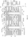
- the variable load valve 34 includes: a pressure regulating valve 50 (an example of the pilot pressure regulating valve) capable of outputting a pressure substantially corresponding to the load compensating pressure for a fully loaded vehicle; and an output valve 51 (an example of the pilot pressure regulating valve) that receives a pressure regulated by the feed valve 30C and the exhaust valve 31C.
- the load compensating pressure for a fully loaded vehicle refers to a pressure substantially corresponding to a pressure to be applied to the brake cylinder 3 to operate the emergency brake when the vehicle is fully loaded.
- the output valve 51 Based on the pressure of the air spring that receives the load of the vehicle, the output valve 51 regulates the pressure of the compressed air input through the input port and outputs a pilot pressure.
- the pressure regulating valve 50 includes an input chamber 50a having an input port, an output chamber 50b having an output port, and a pressure regulating chamber 50c having a pressure regulating port.
- the input chamber 50a receives the source pressure through the input port.
- the pressure regulating chamber 50c is provided with a full load securing spring 50d (an example of the air spring) for limitation to a pressure substantially corresponding to the load compensating pressure for a fully loaded vehicle.
- the pressure regulating valve 50 includes a piston 50e movably supported on the main body of the pressure regulating valve 50.
- the piston 50e regulates the amount of opening of an opening formed in a partition between the input chamber 50a and the output chamber 50b, by the differential pressure between the pressing force of the full load securing spring 50d and the air pressure in the output chamber 50b.
- the piston 50e closes the opening formed in the partition between the input chamber 50a and the output chamber 50b.
- the opening formed in the partition between the input chamber 50a and the output chamber 50b is opened, the compressed air in the input chamber 50a flows into the output chamber 50b.
- the pressure in the output chamber 50b is regulated to a pressure substantially corresponding to the load compensating pressure for a fully loaded vehicle.
- the pressure regulated to the pressure substantially corresponding to the load compensating pressure for a fully loaded vehicle is output through the output port.
- the output valve 51 uses the pressure regulated by the exhaust valve 31C as the pilot pressure to regulate the source pressure to the load compensating pressure in accordance with the current load of the vehicle carrying the passengers.
- the output valve 51 includes an input chamber 51a having an input port for receiving the source pressure, an output chamber 51b having an output port, and a pressure regulating chamber 51c having a pressure regulating port.
- the pressure regulating port receives the pressure regulated by the exhaust valve 31C as the pilot pressure.
- the pressure regulating chamber 51c is provided with an empty load securing spring 51d (an example of the air spring) for generating a load compensating pressure for an empty vehicle.
- the load compensating pressure for an empty vehicle refers to a pressure substantially corresponding to a pressure to be applied to the brake cylinder 3 to operate the emergency brake when the vehicle is empty.
- the empty load securing spring 51d secures at least a pressure substantially corresponding to the load compensating pressure for an empty vehicle if the pilot pressure is lost due to a malfunction or the like.
- the opening between the input chamber 51a and the output chamber 51b can be opened by the elastic force (restoring force) of the empty load securing spring 51d, the interior of the output chamber 51b is maintained at a pressure substantially corresponding to the pressure generated by the elastic force of the empty load securing spring 51d.
- the output valve 51 includes a piston 51e movably supported on the main body of the output valve 51.
- the piston 51e regulates the amount of opening of an opening formed in a partition between the input chamber 51a and the output chamber 51b, by the differential pressure between the total pressure of the pressure generated by the elastic force of the empty load securing spring 51d and the air pressure in the pressure regulating chamber 50c and the air pressure in the output chamber 51b.
- the piston 51e closes the opening formed in the partition between the input chamber 51a and the output chamber 51b.
- the opening formed in the partition between the input chamber 51a and the output chamber 51b is opened, the compressed air in the input chamber 51a flows into the output chamber 51b.
- the pressure in the output chamber 51b is regulated to the load compensating pressure.
- the emergency pilot pressure generating unit 46 includes one each of pressure regulating valve 50, output valve 51, feed valve 30C, exhaust valve 31C, and pilot pressure sensor 42B, but this configuration is not limitative.
- the emergency pilot pressure generating unit 46 may include two or more each of pressure regulating valve 50, output valve 51, feed valve 30, exhaust valve 31, and pilot pressure sensor 42.
- the emergency pilot pressure generating unit 46 may be formed of either the same number or different numbers of components.
- the configuration of the emergency pilot pressure generating unit 46 can be modified in accordance with required specifications.
- the above system including the normal pilot pressure generating unit 45 and the emergency pilot pressure generating unit 46 is a mere example and can be modified in accordance with required specifications.
- the emergency pilot pressure generating unit 46 does not include the regulating valves 30C, 31C, and an average pressure of the air spring pressure sensors 41A to 41D is directly input to the variable load valve 34 to generate the emergency pilot pressure without electronic control.
- the air spring pressure sensors 41A to 41D are fixed to a relay valve (not shown) instead of the tube seat 10.
- Fig. 3 is a perspective view showing the tube seat 10 of the first embodiment.
- Fig. 4 is a top view showing the tube seat 10 of the first embodiment.
- Fig. 5 is a side view showing the tube seat 10 of the first embodiment.
- the tube seat 10 is formed of a plurality of plate-shaped members 11 to 17 and 20 to 24 laminated together in the Z direction.
- the plurality of plate-shaped members 11 to 17 and 20 to 24 forming the tube seat 10 are brazed together (an example of metal joining). Specifically, any two of the plurality of plate-shaped members 11 to 17 and 20 to 24 adjacent to each other in the lamination direction (the Z direction) are brazed together at respective surfaces facing each other.
- the method of joining the plurality of plate-shaped members 11 to 17 and 20 to 24 is not limited to brazing but may be any of other interface joining methods or welding methods.
- Examples of other interface joining methods include liquid phase bonding such as liquid phase diffusion bonding and solid phase bonding such as solid phase diffusion bonding, sinter bonding, and ultrasonic bonding.
- Examples of welding methods include arc welding, high energy beam welding, and resistance welding.
- the joining method of the plurality of plate-shaped members 11 to 17 and 20 to 24 can be changed in accordance with required specifications.
- the channels A to W (see Fig. 2 ) connecting between the input port 5 of the tube seat 10 and the regulating valves 30 to 35 are formed by the plurality of plate-shaped members 11 to 17 and 20 to 24.
- the channels A to W formed by the plurality of plate-shaped members 11 to 17 and 20 to 24 are as follows.
- the channel between the input port 5 of the tube seat 10 and the port 34a of the variable load valve 34 is a "channel A”
- the channels between a halfway point of the channel A and the normal pilot pressure generating unit 45 are “channels B to C”
- the channels between the normal pilot pressure generating unit 45 and the double check valve 35 are “channels D to G”
- the channel connected to one of the exhaust ports of the normal pilot pressure generating unit 45 is a "channel H
- the channel connected to the other of the exhaust ports of the normal pilot pressure generating unit 45 (specifically, the output port of the exhaust valve 31B) is a "channel I”
- the channel connecting between the output port 35b of the double check valve 35 and the input port of the electromagnetic valve 32 is a "channel J”
- the channel between the output port of the electromagnetic valve 32 and the output port 7 of the tube seat 10 is a "channel K”
- the compressed air flowing through the input port 5 of the tube seat 10 into the channel A passes through the port 34a of the variable load valve 34 and the channel in the variable load valve 34 and flows into the input chamber 50a of the pressure regulating valve 50 and the input chamber 51a of the output valve 51.
- the channel B connects between a halfway point of the channel A and the input port of the feed valve 30A.
- the channel C connects between a halfway point of the channel B and the input port of the feed valve 30B.
- the compressed air flowing through the channel A into the channel B passes through the input port of the feed valve 30A and flows into the feed valve 30A.
- the compressed air flowing through the channel B into the channel C passes through the input port of the feed valve 30B and flows into the feed valve 30B.
- the channel D connects between the output port of the feed valve 30A and the input port of the double check valve 35.
- the channel E connects between the output port of the feed valve 30B and a halfway point of the channel D.
- the channel F connects between a halfway point of the channel D and the input port of the exhaust valve 31A.
- the channel G connects between a halfway point of the channel F and the input port of the exhaust valve 31B.
- the compressed air flowing through the channels B, C into the feed valves 30A, 30B, respectively passes through the channels D to G, H, and I and is regulated in flow rate or pressure by the normal pilot pressure generating unit 45 (the feed valves 30 and the exhaust valves 31).
- the compressed air regulated in flow rate or pressure by the normal pilot pressure generating unit 45 passes through the input port 35a, which is one of the input ports of the double check valve 35, and flows into the double check valve 35.
- the compressed air flowing into the double check valve 35 passes through the output port 35b of the double check valve 35, the channel J, and the input port of the electromagnetic valve 32 and flows into the electromagnetic valve 32.
- the compressed air flowing into the electromagnetic valve 32 is passed through the output port of the electromagnetic valve 32, the channel K, and the output port 7 of the tube seat 10, regulated in flow rate or pressure by a relay valve (not shown), and directed to the brake cylinder 3.
- the compressed air flowing into the input chamber 50a of the pressure regulating valve 50 and the input chamber 51a of the output valve 51 passes through the channels L, M, N, O, and P and is regulated in flow rate or pressure by the emergency pilot pressure generating unit 46 (the variable load valve 34, the feed valve 30C, the exhaust valve 31C, and the pilot pressure sensor 42B).
- the compressed air regulated in flow rate or pressure by the emergency pilot pressure generating unit 46 passes through the port of the variable load valve 34 (in other words, the port leading to the air spring port 6), the channel Q, and the input port of the emergency valve 33 and flows into the emergency valve 33.
- the emergency valve 33 is opened in an emergency, and thus the compressed air flowing into the emergency valve 33 passes through the output port of the emergency valve 33, the channel S, and the input port 35c, which is the other of the input ports of the double check valve 35, and flows into the double check valve 35.
- the compressed air flowing into the double check valve 35 passes through the output port 35b of the double check valve 35, the channel J, and the input port of the electromagnetic valve 32 and flows into the electromagnetic valve 32.
- the compressed air flowing into the electromagnetic valve 32 is passed through the output port of the electromagnetic valve 32, the channel K, and the output port 7 of the tube seat 10, regulated in flow rate or pressure by a relay valve (not shown), and directed to the brake cylinder 3.
- the tube seat 10 includes the channels A to W described above and openings 10a to 10e located at different positions than the channels A to W.
- the portions of the channels A to W open toward the +Z side specifically, the +Z side ends of the channels B to O and Q to W
- the openings 10a to 10e are formed to have a circular shape in top view.
- the plurality of openings 10a to 10d include various openings such as: valve mounting openings 10a for mounting the regulating valves 30 to 33 (for example, female screw portions threadably engaged with bolts, which are an example of valve fasteners); sensor mounting openings 10b for mounting the pressure sensors 41 to 43 (for example, female screw portions threadably engaged with bolts, which are an example of sensor fasteners); openings 10c to 10e for positioning and mounting the tube seat 10; and an exhaust opening 10f leading to the exhaust port of the emergency valve 33 (see Fig. 2 ).
- the aspect of the openings is not limited to the above but may be modified in accordance with required specifications.
- the openings (the +Z side ends) of the channels B to O, Q, and S positioned in the area AR1 of the tube seat 10 are located in respective areas overlapping the associated regulating valves 30 to 33 (see Fig. 1 ) in top view.
- the openings of the channels B to H are positioned near the +Y end of the area AR1 in top view.
- the openings of the channels B, D are positioned in the area overlapping the associated feed valve 30A (see Fig. 1 ) in top view and are spaced apart from each other in the Y direction.
- the opening of the channel B leads to the input port of the feed valve 30A (see Fig. 2 ).
- the opening of the channel D leads to the output port of the feed valve 30A (see Fig. 2 ).
- the openings of the channels C, E are positioned in the area overlapping the associated feed valve 30B (see Fig. 1 ) in top view and are spaced apart from each other in the Y direction.
- the opening of the channel C leads to the input port of the feed valve 30B (see Fig. 2 ).
- the opening of the channel E leads to the output port of the feed valve 30B (see Fig. 2 ).
- the openings of the channels F, H are positioned in the area overlapping the associated exhaust valve 31A (see Fig. 1 ) in top view and are spaced apart from each other in the Y direction.
- the opening of the channel F leads to the input port of the exhaust valve 31A (see Fig. 2 ).
- the opening of the channel H leads to the output port of the exhaust valve 31A (see Fig. 2 ).
- the openings of the channels G, I are positioned in the area overlapping the associated exhaust valve 31B (see Fig. 1 ) in top view and are spaced apart from each other in the Y direction.
- the opening of the channel G leads to the input port of the exhaust valve 31B (see Fig. 2 ).
- the opening of the channel I leads to the output port of the exhaust valve 31B (see Fig. 2 ).
- the openings of the channels J to O, Q, and S are positioned near the -Y end of the area AR1 in top view.
- the openings of the channels J, K are positioned in the region overlapping the associated electromagnetic valve 32 (see Fig. 1 ) in top view and are spaced apart from each other in the Y direction.
- One of the openings of the channel J (the opening on the +X side) leads to the input port of the electromagnetic valve 32 (see Fig. 2 ).
- the opening of the channel K leads to the output port of the electromagnetic valve 32 (see Fig. 2 ).
- the openings of the channels L, M are positioned in the region overlapping the associated feed valve 30C (see Fig. 1 ) in top view and are spaced apart from each other in the Y direction.
- the opening of the channel L leads to the input port of the feed valve 30C (see Fig. 2 ).
- One of the openings of the channel M (the opening on the +X side) leads to the output port of the feed valve 30C (see Fig. 2 ).
- the openings of the channels N, O are positioned in the region overlapping the associated exhaust valve 31C (see Fig. 1 ) in top view and are spaced apart from each other in the Y direction.
- the opening of the channel N leads to the input port of the exhaust valve 31C (see Fig. 2 ).
- the opening of the channel O leads to the output port of the exhaust valve 31C (see Fig. 2 ).
- the openings of the channels Q, S are positioned in the region overlapping the associated emergency valve 33 (see Fig. 1 ) in top view and are spaced apart from each other in the Y direction.
- the opening of the channel Q leads to the input port of the emergency valve 33 (see Fig. 2 ).
- the opening of the channel S leads to the output port of the emergency valve 33 (see Fig. 2 ).
- Two valve mounting openings 10a are provided for each of the associated regulating valves 30 to 33 (see Fig. 1 ).
- the two valve mounting openings 10a are spaced apart from each other in the X direction so as to be positioned on opposite sides of the openings of the channels B to O, Q, and S located in the regions overlapping the associated regulating valves 30 to 33 in top view.
- a plurality (for example, four in the embodiment) of openings 10c are provided.
- the four openings 10c are positioned one at each of the four corners of the area AR1 that has a rectangular shape in top view.
- the exhaust opening 10f is positioned near the -Y end of the area AR1 in top view.
- the exhaust opening 10f is spaced apart from the opening of the channel S in the Y direction.
- the openings (the +Z side ends) of the channels J, M, R, and T to W positioned in the area AR2 of the tube seat 10 are located in respective areas overlapping the associated pressure sensors 41 to 43 (see Fig. 1 ) in top view.
- the openings of the channels J, M, R, and T to W positioned in the area AR2 are located in the middle in the Y direction in top view (specifically, between the openings of the channels B to H and the opening of the channels J to O, Q, and S in the Y direction).
- the openings of the channel J (the two openings of the channel J in the example shown) positioned in the area AR2 are located in the area overlapping the associated pilot pressure sensor 42A (see Fig. 1 ) in top view and are spaced apart from each other in the X direction.
- the openings of the channels M, R positioned in the area AR2 are located in the area overlapping in top view the sensor unit 40C (see Fig. 1 ) including the pilot pressure sensor 42B and the air spring pressure sensor 43 associated therewith, and the openings of the channels M, R are spaced apart from each other in the X direction.
- the openings of the channels T, U positioned in the area AR2 are located in the area overlapping in top view the sensor unit 40A (see Fig.
- the openings of the channels V, W positioned in the area AR2 are located in the area overlapping in top view the sensor unit 40B (see Fig. 1 ) including the air spring pressure sensors 41C, 41D associated therewith, and the openings of the channels V, W are spaced apart from each other in the X direction.
- Two sensor mounting openings 10b are provided for each of the pilot pressure sensor 42A and the sensor units 40A to 40C (see Fig. 1 ) associated therewith.
- the two sensor mounting openings 10b are spaced apart from each other in both the X direction and the Y direction so as to be positioned on opposite sides of the openings of the channels J, M, R, and T to W located in the regions overlapping in top view the pilot pressure sensor 42A and the sensor units 40A to 40C associated therewith.
- a plurality (for example, two in the embodiment) of openings 10d are provided.
- One of the openings 10d is positioned on the +X side and near the +Y end of the area AR2 in top view.
- the other of the openings 10d is positioned on the -Y side and near the -X end of the area AR2 in top view.
- a plurality (for example, six in the embodiment) of openings 10e are provided. Two of the plurality of openings 10e are positioned near the +Y end of the tube seat 10 in top view and are spaced apart from each other in the X direction so as to be positioned on opposite sides of one of the openings 10d. Three of the plurality of openings 10e are positioned near the -Y end of the tube seat 10 in top view and are spaced apart from each other in the X direction. One of the openings 10d is positioned on the +Y side and near the -X end of the tube seat 10 in top view.
- the tube seat 10 includes a plurality (for example, seven in the embodiment) of plate members 11 to 17, a sub plate 20 (an example of the outermost plate-shaped member of the plurality of plate-shaped members), and a plurality (for example, four in the embodiment) of brazing sheets 21 to 24.
- the plurality of plate members 11 to 17 include a first plate member 11 (an example of the outermost plate-shaped member of the plurality of plate-shaped members), a second plate member 12, a third plate member 13, a fourth plate member 14, a fifth plate member 15, a sixth plate member 16, and a seventh plate member 17 (an example of the outermost plate-shaped member of the plurality of plate-shaped members).
- the plurality of brazing sheets 21 to 24 include two first brazing sheets 21, two second brazing sheets 22, two third brazing sheets 23, and a fourth brazing sheet 24.
- the tube seat 10 is formed of the plate members 17 and the brazing sheets 21 to 24 stacked alternately.
- the sub plate 20 is provided on the top of the tube seat 10.
- the portion of the tube seat 10 except the sub plate 20 and the fourth brazing sheet 24 includes the following that are laminated in the downward direction: the first plate member 11, one of the first brazing sheets 21, the second plate member 12, the other of the first brazing sheets 21, the third plate member 13, one of the second brazing sheets 22, the fourth plate member 14, the other of the second brazing sheets 22, the fifth plate member 15, one of the third brazing sheets 23, the sixth plate member 16, the other of the third brazing sheets 23, and the seventh plate member 17.
- the sub plate 20 is provided on the upper surface of the first plate member 11 via the fourth brazing sheet 24.
- the plate members 11 to 17 and the sub plate 20 are formed of a metal such as an aluminum alloy.
- the substance of the plate members 11 to 17 and the sub plate 20 is not limited to the above but may be modified in accordance with required specifications.
- the brazing sheets 21 to 24 are formed of a core material and a brazing material having a lower melting point than the core material.
- the brazing sheets 21 to 24 are formed of an aluminum alloy clad with an Al-Si alloy, or what is called aluminum brazing sheets.
- the substance of the brazing sheets 21 to 24 is not limited to the above but may be modified in accordance with required specifications.
- the brazing sheets 21 to 24 are what is called double-sided clads formed of a core material and a brazing material provided on both sides of the core material.
- the aspect of the brazing sheets 21 to 24 is not limited to the above.
- the brazing sheets 21 to 24 may be what is called single-sided clads formed of a core material and a brazing material provided on only one side of the core material.
- the aspect of the brazing sheets 21 to 24 can be modified in accordance with required specifications.
- each of the plate members 11 to 17 has the same thickness.
- each of the plate members 11 to 17 has a thickness from 1.8 mm to 2.2 mm.
- the sub plate 20 has a smaller thickness than the plate members 11 to 17.
- the sub plate 20 has a thickness from 1.3 mm to 1.7 mm.
- each of the brazing sheets 21 to 24 has the same thickness.
- each of the brazing sheets 21 to 24 has a smaller thickness than the sub plate 20.
- each of the brazing sheets 21 to 24 has a thickness from 0.6 mm to 1.0 mm.
- the thicknesses of the components of the tube seat 10 are not limited to the above but may be modified in accordance with required specifications.
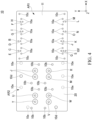
- Fig. 6 is a top view showing the first plate member 11 forming the tube seat 10 of the first embodiment.
- the first plate member 11 is shaped like a rectangular plate which is long in the X direction and short in the Y direction.
- the first plate member 11 has openings B11 to O11 and Q11 to W11 and openings 10a11 to 10f 11 associated with the channels B to O and Q to W and the openings 10a to 10f (see Fig. 4 ) described above.
- the openings of the first plate member 11 that form a part of the channels or the openings of the tube seat 10 described above are denoted by reference signs ending with "11."
- the openings B11 to O11 and Q11 to W11 and the openings 10a11 to 10f11 are open in the thickness direction of the first plate member 11.
- the openings B11 to O11 and Q11 to W11 and the openings 10a11 to 10f 11 have a circular shape in top view.
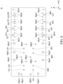
- Fig. 7 is a top view showing the second plate member 12 forming the tube seat 10 of the first embodiment.
- the second plate member 12 is shaped like a rectangular plate which is long in the X direction and short in the Y direction.
- the second plate member 12 has openings B12 to 012 and Q12 to W12 and openings 10a12 to 10f12 associated with the channels B to O and Q to W and the openings 10a to 10f (see Fig. 4 ) described above.
- the openings of the second plate member 12 that form a part of the channels or the openings of the tube seat 10 described above are denoted by reference signs ending with "12."
- the openings B12, C12, K12, L12, M12, S12, and 10a12 to 10e12 of the second plate member 12 have a circular shape and overlap in top view the openings B11, C11, K11, L11, M11, S11, and 10a11 to 10e11 of the first plate member 11 (see Fig. 6 ), respectively.
- the second plate member 12 has an opening 12a including the openings D12 to G12.
- the opening 12a extends from the opening F12 side toward the -X side (specifically, to the position between the opening 10d12 near the +Y end and the opening 10e12 in the X direction) in top view.
- the opening H12 is positioned on the extension of the opening F12, which is included in the opening 12a and extends in the Y direction in top view.
- the opening H12 is a recess formed from the +Y end surface of the second plate member 12 toward the -Y side.
- the opening I12 is positioned on the extension of the opening G12, which is included in the opening 12a and extends in the Y direction in top view.
- the opening 112 is a recess formed toward the -Y side from the portion of the +Y end surface of the second plate member 12 positioned on the -X side relative to the opening H12.
- the opening J12 is positioned on the -Y side relative to the opening 12a.
- the opening J12 includes an opening J12a extending from the position overlapping the opening J11 (see Fig. 6 ) toward the +Y side, an opening J12b extending obliquely from the +Y end of the opening J12a so as to be closer to the +Y side toward the -X side, an opening J12c extending from the -X end of the opening J12b toward the -X side, and an opening J12d extending obliquely from the -X end of the opening J12c so as to be closer to the -Y side toward the -X side.
- the opening 012 is positioned on the +X side relative to the opening J12. In top view, the opening 012 extends from the position overlapping the opening O11 (see Fig. 6 ) toward the +Y side and bends in an arc-like shape toward the +X side, and then the opening 012 extends toward the +X end of the second plate member 12.
- the +X end of the opening 012 is open in the -Y side portion of the +X end surface of the second plate member 12.
- the opening Q12 is provided in the -Y side portion of the second plate member 12.
- the opening Q12 is positioned on the opposite side of the opening J12 to the opening 012 in the X direction.
- the opening Q12 includes an opening Q12a extending from the position overlapping the opening Q11 (see Fig. 6 ) of the first plate member 11 toward the +Y side, an opening Q12b extending obliquely from the +Y end of the opening Q12a so as to be closer to the +Y side toward the -X side, and an opening Q12c extending from the -X end of the opening Q12b toward the -X side to the position overlapping the opening R11 (see Fig. 6 ) of the first plate member 11.
- the opening 10f12 is positioned on the extension of the opening Q12a and on the -Y side relative to the opening S12.
- the opening 10f12 is a recess formed from the -Y end surface of the second plate member 12 toward the +Y side.
- the opening T12 is positioned in the +Y side portion of the -X end of the second plate member 12. In top view, the opening T12 extends from the position overlapping the opening T11 (see Fig. 6 ) of the first plate member 11 toward the - X side.
- the opening U12 has a straight shape longer than the opening T12. In top view, the opening U12 extends obliquely from the position overlapping the opening U11 (see Fig. 6 ) of the first plate member 11 so as to be closer to the -X side toward the +Y side.
- the opening V12 is provided in the -Y side portion of the -X end of the second plate member 12. In top view, the opening V12 extends from the position overlapping the opening V11 (see Fig. 6 ) of the first plate member 11 toward the - X side.
- the opening W12 has a straight shape longer than the opening V12. In top view, the opening W12 extends obliquely from the position overlapping the opening W11 (see Fig. 6 ) of the first plate member 11 so as to be closer to the -X side toward the -Y side.
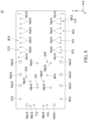
- Fig. 8 is a top view showing the third plate member 13 forming the tube seat 10 of the first embodiment.
- the third plate member 13 is shaped like a rectangular plate which is long in the X direction and short in the Y direction.
- the third plate member 13 has openings B13 to D13, J13 to N13, Q13, and S13 to W13 and openings 10a13 to 10e13 associated with the channels B to D, J to N, Q, and S to W and the openings 10a to 10e (see Fig. 4 ) described above.
- the openings of the third plate member 13 that form a part of the channels or the openings of the tube seat 10 described above are denoted by reference signs ending with "13.”
- the openings B13, C13, K13 to N13, and S13 and the openings 10a13 to 10e13 of the third plate member 13 have a circular shape and overlap in top view the openings B12, C12, K12 to N12, and S12 and the openings 10a12 to 10e12 of the second plate member 12 (see Fig. 7 ), respectively.
- the opening D13 of the third plate member 13 has a circular shape and is positioned to overlap the -X end of the opening 12a of the second plate member 12 (see Fig. 7 ) in top view.
- the opening J13 of the third plate member 13 has a circular shape and is positioned to overlap the -X end of the opening J12d of the second plate member 12 (see Fig. 7 ) in top view.
- the opening Q13 of the third plate member 13 has a circular shape and is positioned to overlap a halfway point of the opening Q12c of the second plate member 12 (see Fig. 7 ) in top view.
- the opening T13 of the third plate member 13 has a circular shape and is positioned to overlap the -X end of the opening T12 of the second plate member 12 (see Fig.
- the opening U13 of the third plate member 13 has a circular shape and is positioned to overlap the +Y end of the opening U12 of the second plate member 12 (see Fig. 7 ) in top view.
- the opening V13 of the third plate member 13 has a circular shape and is positioned to overlap the -X end of the opening V12 of the second plate member 12 (see Fig. 7 ) in top view.
- the opening W13 of the third plate member 13 has a circular shape and is positioned to overlap the -Y end of the opening W12 of the second plate member 12 (see Fig. 7 ) in top view.
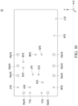
- Fig. 9 is a top view showing the fourth plate member 14 forming the tube seat 10 of the first embodiment.
- the fourth plate member 14 is shaped like a rectangular plate which is long in the X direction and short in the Y direction.
- the fourth plate member 14 has openings A14, B14 to D14, J14 to N14, P14, Q14, and S14 to W14 and openings 10a14 to 10e14 associated with the channels A to D, J to N, P, Q, and S to W and the openings 10a to 10e (see Fig. 4 ) described above.
- the openings of the fourth plate member 14 that form a part of the channels or the openings of the tube seat 10 described above are denoted by reference signs ending with "14.”
- the openings D14, J14 to L14, Q14, and T14 to W14 and the openings 10a14 to 10e14 of the fourth plate member 14 have a circular shape and overlap in top view the openings D13, J13 to L13, Q13, and T13 to W13 and the openings 10a13 to 10e13 of the third plate member 13 (see Fig. 8 ), respectively.
- the opening A14 is provided in the -X side portion of the fourth plate member 14. In top view, the opening A14 extends obliquely from the point of intersection of the line passing through the center of the opening T14 and extending along the X direction with the line passing through the center of the opening U14 and extending along the Y direction, so as to be closer to the +X side toward the -Y side.
- the fourth plate member 14 has an opening 14a including the openings B14 and C14.
- the opening 14a extends from the opening B14 side toward the -X side (specifically, to the position near the +X side of the opening D14) in top view.
- the opening M14 is positioned on the -Y side relative to the opening 14a in top view.
- the opening M14 includes an opening M14a extending from the position overlapping one of the openings M13 of the third plate member 13 (the opening M13 on the +X side; see Fig. 8 ) toward the +Y side, an opening M14b bending in an arc-like shape from the +Y end of the opening M14a toward the -X side and then extending toward the -X side, and an opening M14c extending obliquely from the -X end of the opening M14b so as to be closer to the -Y side toward the -X side.
- the opening N14 of the fourth plate member 14 is positioned to overlap the opening N13 of the third plate member 13 (see Fig. 8 ) in top view.
- the opening P14 extends from the opening N14 toward the +Y side and is connected to a halfway point of the opening M14b in top view.
- the opening S14 is provided in the -Y side portion of the fourth plate member 14.
- the opening S14 includes an opening S14a extending from the position overlapping the opening S13 (see Fig. 8 ) of the third plate member 13 toward the +Y side, bending toward the -X side, and then extending toward the -X side, an opening S14b extending obliquely from the -X end of the opening S14a so as to be closer to the +Y side toward the -X side, and an opening S14c extending from the +Y end of the opening S14b toward the +Y side.
- Fig. 10 is a top view showing the fifth plate member 15 forming the tube seat 10 of the first embodiment.
- the fifth plate member 15 is shaped like a rectangular plate which is long in the X direction and short in the Y direction.
- the fifth plate member 15 has openings A15, B15, D15, J15 to M15, Q15, and S15 to W15 and openings 10d15 and 10e15 associated with the channels A, B, D, J to M, Q, and S to W and the openings 10d and 10e (see Fig. 4 ) described above.
- the openings of the fifth plate member 15 that form a part of the channels or the openings of the tube seat 10 described above are denoted by reference signs ending with "15.”
- the openings D15, J15 to L15, Q15, and T15 to W15 and the openings 10d15 and 10e15 of the fifth plate member 15 have a circular shape and overlap in top view the openings D14, J14 to L14, Q14, and T14 to W14 and the openings 10d14 and 10e14 of the fourth plate member 14 (see Fig. 9 ), respectively.
- One of the openings A15 of the fifth plate member 15 (the opening A15 on the -X side) has a circular shape and is located at the position overlapping the +Y end of the opening A14 of the fourth plate member 14 (see Fig. 9 ) in top view (specifically, the point of intersection of the line passing through the center of the opening T15 and extending along the X direction with the line passing through the center of the opening U15 and extending along the Y direction).
- the other of the openings A15 of the fifth plate member 15 (the opening A15 on the +X side relative to the one of the openings A15) has a circular shape and is positioned to overlap the -Y end of the opening A14 of the fourth plate member 14 (see Fig. 9 ) in top view.
- the opening B15 of the fifth plate member 15 has a circular shape and is positioned to overlap the -X end of the opening 14a of the fourth plate member 14 in top view.
- the opening M15 of the fifth plate member 15 has a circular shape and is positioned to overlap the -X end of the opening M14b of the fourth plate member 14 (in other words, the +X end of the opening M14c; see Fig. 9 ) in top view.
- the opening S15 of the fifth plate member 15 has a circular shape and is positioned to overlap the +Y end of the opening S14c of the fourth plate member 14 (see Fig. 9 ) in top view.
- Fig. 11 is a top view showing the sixth plate member 16 forming the tube seat 10 of the first embodiment.
- the sixth plate member 16 is shaped like a rectangular plate which is long in the X direction and short in the Y direction.
- the sixth plate member 16 has openings A16, B16, D16, J16 to M16, Q16, and S16 to W16 and openings 10d16 and 10e16 associated with the channels A, B, D, J to M, Q, and S to W and the openings 10d and 10e (see Fig. 4 ) described above.
- the openings of the sixth plate member 16 that form a part of the channels or the openings of the tube seat 10 described above are denoted by reference signs ending with "16.”
- the openings A16, J16, M16, and S16 to W16 and the openings 10d16 and 10e16 of the sixth plate member 16 have a circular shape and overlap in top view one of the openings A15 (the opening A15 on the -X side), the openings J15, M15, and S15 to W15, and the openings 10d15 and 10e15 of the fifth plate member 15 (see Fig. 10 ), respectively.
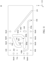
- the opening B16 is provided in the -X side portion of the sixth plate member 16.
- the opening B16 includes an opening B16a extending from the position overlapping the other of the openings A15 of the fifth plate member 15 (the opening A15 on the +X side relative to the one of the openings A15) toward the +X side, an opening B16b extending obliquely from the +X end of the opening B 16a so as to be closer to the +Y side toward the +X side, and an opening B16c extending from the +Y end of the opening B16b toward the +Y side to the position overlapping the opening B15 of the fifth plate member 15.
- the opening D16 is positioned on the -X side relative to the opening B16c. In top view, the opening D16 extends obliquely from the position overlapping the opening D15 of the fifth plate member 15 so as to be closer to the -Y side toward the -X side, and then the opening D16 bends in an arc-like shape and extends toward the -Y side.
- the opening K16 is provided in the -Y side portion of the sixth plate member 16.
- the opening K16 includes an opening K16a extending from the position overlapping the opening K15 (see Fig. 10 ) of the fifth plate member 15 toward the +Y side, bending toward the -X side, and then extending toward the -X side, and an opening K16b bending from the -X end of the opening K16a toward the +Y side and then extending toward the +Y side.
- the opening L16 extends straight and obliquely to both the X direction and the Y direction. In top view, the opening L16 extends obliquely from the position overlapping the opening L15 (see Fig. 10 ) of the fifth plate member 15 to the middle position between the opening M16 and the opening 10e16 in the Y direction, so as to be closer to the +Y side toward the -X side.
- the opening Q16 is positioned between the opening M16 and the opening K16a. In top view, the opening Q16 extends from the position overlapping the opening Q15 (see Fig. 10 ) of the fifth plate member 15 toward the -Y side.
- Fig. 12 is a top view showing the seventh plate member 17 forming the tube seat 10 of the first embodiment.
- the seventh plate member 17 is shaped like a rectangular plate which is long in the X direction and short in the Y direction.
- the seventh plate member 17 has openings A17, B17, D17, J17 to M17, Q17, and S17 to W17 and openings 10d17 and 10e17 associated with the channels A, B, D, J to M, Q, and S to W and the openings 10d and 10e (see Fig. 4 ) described above.
- the openings of the seventh plate member 17 that form a part of the channels or the openings of the tube seat 10 described above are denoted by reference signs ending with "17.”
- the openings A17, J17, M17, and S17 to W17 and the openings 10d17 and 10e17 of the seventh plate member 17 have a circular shape and overlap in top view the openings A16, J16, M16, and S16 to W16, and the openings 10d16 and 10e16 of the sixth plate member 16 (see Fig. 11 ), respectively.
- the opening B17 of the seventh plate member 17 has a circular shape and is positioned to overlap the -Y end of the opening B16c of the sixth plate member 16 (see Fig. 11 ) in top view.
- the opening D17 of the seventh plate member 17 has a circular shape and is positioned to overlap the -Y end of the opening D16 of the sixth plate member 16 (see Fig. 11 ) in top view.
- the opening K17 of the seventh plate member 17 has a circular shape and is positioned to overlap the +Y end of the opening K16b of the sixth plate member 16 (see Fig. 11 ) in top view.
- the opening L17 of the seventh plate member 17 has a circular shape and is positioned to overlap the -X end of the opening L16 of the sixth plate member 16 (see Fig. 11 ) in top view.
- the opening Q17 of the seventh plate member 17 has a circular shape and is positioned to overlap the -Y end of the opening Q16 of the sixth plate member 16 (see Fig. 11 ) in top view.
- the opening A17 of the seventh plate member 17 corresponds to the input port 5 of the tube seat 10.
- the opening J17 leads to the output port 35b of the double check valve 35 (see Fig. 2 ).
- the opening K17 corresponds to the output port 7 of the tube seat 10.
- the opening L17 leads to the port 34b of the variable load valve 34 (see Fig. 2 ).
- the opening S17 leads to the other input port 35c of the double check valve 35 (see Fig. 2 ).
- the openings T17 to W17 lead to ports (not shown) of the double check valve 35.
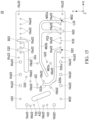
- Fig. 13 is a top view showing a sub plate 20 forming the tube seat 10 of the first embodiment.
- the sub plate 20 is shaped like a rectangular plate having a side along the X direction and a side along the Y direction.
- the sub plate 20 has openings J20, M20, R20, and T20 to W20 and openings 10b20 and 10d20 associated with the channels J, M, R, and T to W and the openings 10b and 10d (see Fig. 4 ) described above.
- the openings of the sub plate 20 that form a part of the channels or the openings of the tube seat 10 described above are denoted by reference signs ending with "20.”
- the openings J20, M20, R20, and T20 to W20 and the openings 10b20 and 10d20 are open in the thickness direction of the sub plate 20.
- the openings J20, M20, R20, and T20 to W20 and the openings 10b20 and 10d20 have a circular shape in top view.
- the openings J20, M20, R20, and T20 to W20 of the sub plate 20 have a larger diameter than the openings J11, M11, R11, and T11 to W11 (see Fig. 6 ) of the first plate member 11, respectively.
- Fig. 14 is a top view showing a first brazing sheet 21 forming the tube seat 10 of the first embodiment.
- the first brazing sheet 21 is shaped like a rectangular plate which is long in the X direction and short in the Y direction.
- the first brazing sheet 21 has the same shape as the second plate member 12 (see Fig. 7 ) described above.
- the first brazing sheet 21 has openings B21 to 021 and Q21 to W21 and openings 10a21 to 10f21 associated with the channels B to O and Q to W and the openings 10a to 10f (see Fig. 4 ) described above.
- the openings of the first brazing sheet 21 that form a part of the channels or the openings of the tube seat 10 described above are denoted by reference signs ending with "21" appended thereto or substituted for "12."
- Fig. 15 is a top view showing a second brazing sheet 22 forming the tube seat 10 of the first embodiment.
- the second brazing sheet 22 is shaped like a rectangular plate which is long in the X direction and short in the Y direction.
- the second brazing sheet 22 has the same shape as the fourth plate member 14 (see Fig. 9 ) described above.
- the second brazing sheet 22 has openings A22, B22 to D22, J22 to N22, P22, Q22, and S22 to W22 and openings 1 0a22 to 10e22 associated with the channels A to D, J to N, P, Q, and S to W and the openings 10a to 10e (see Fig. 4 ) described above.
- the openings of the second brazing sheet 22 that form a part of the channels or the openings of the tube seat 10 described above are denoted by reference signs ending with "22" appended thereto or substituted for "14.”
- Fig. 16 is a top view showing a third brazing sheet 23 forming the tube seat 10 of the first embodiment.
- the third brazing sheet 23 is shaped like a rectangular plate which is long in the X direction and short in the Y direction.
- the third brazing sheet 23 has the same shape as the sixth plate member 16 (see Fig. 11 ) described above.
- the third brazing sheet 23 has openings A23, B23, D23, J23 to M23, Q23, and S23 to W23 and openings 10d23 and 10e23 associated with the channels A, B, D, J to M, Q, and S to W and the openings 10d and 10e (see Fig. 4 ) described above.
- the openings of the third brazing sheet 23 that form a part of the channels or the openings of the tube seat 10 described above are denoted by reference signs ending with "23" appended thereto or substituted for "16.”
- Fig. 17 is a top view showing a fourth brazing sheet 24 forming the tube seat 10 of the first embodiment.
- the fourth brazing sheet 24 is shaped like a rectangular plate having a side along the X direction and a side along the Y direction.
- the fourth brazing sheet 24 has the same shape as the sub plate 20 (see Fig. 13 ) described above.
- the fourth brazing sheet 24 has openings J24, M24, R24, and T24 to W24 and openings 10b24 and 10d24 associated with the channels J, M, R, and T to W and the openings 10b and 10d (see Fig. 4 ) described above.
- the openings of the fourth brazing sheet 24 that form a part of the channels or the openings of the tube seat 10 described above are denoted by reference signs ending with "24" appended thereto or substituted for "20.”
- the channels A to W are formed by a plurality of plate-shaped members 11 to 17 and 20 to 24 constituting the tube seat 10.
- the tube seat 10 is formed of the brazing sheets 21 to 24 (an example of plate-shaped members having a first thickness) and the plate members 11 to 17 and 20 (an example of plate-shaped members having a second thickness larger than the first thickness) stacked alternately.
- This alternate configuration indicates that adhesive layers such as those formed of a brazing material may be interposed between the plate members.
- the channels A to W are formed by the brazing sheets 21 to 24 and the plate members 11 to 17 and 20.
- the channel A, B (an example of a channel) extending from the input port 5 of the tube seat 10 to the input port of the feed valve 30A is constituted by the channel A and the channel B.
- the channel A (an example of a first channel extending in an in-plane direction) is connected to the input port 5 of the tube seat 10, and the channel B (an example of a second channel extending in an in-plane direction) connected to the input port of the feed valve 30A.
- the extension in an in-plane direction mentioned above indicates a direction along the surface of the plate members as viewed from the thickness direction of the plate members. As shown in Fig.
- the plurality of plate-shaped members 11 to 17 and 20 to 24 include: the fourth plate member 14 having the channel A (an example of a plate-shaped member having a first channel); the sixth plate member 16 having the channel B (an example of a plate-shaped member having a second channel); and the fifth plate member 15 provided between the fourth plate member 14 and the sixth plate member 16 (an example of a plate-shaped member having only a hole connecting between one end of the first channel and one end of the second channel).
- the fourth plate member 14 having the channel A an example of a plate-shaped member having a first channel
- the sixth plate member 16 having the channel B (an example of a plate-shaped member having a second channel)
- the fifth plate member 15 provided between the fourth plate member 14 and the sixth plate member 16 (an example of a plate-shaped member having only a hole connecting between one end of the first channel and one end of the second channel).
- the fifth plate member 15 has the opening A15 (an example of only the hole connecting between one end of the first channel and one end of the second channel) that connects between one end of the opening A14 of the fourth plate member 14 (an example of one end of the first channel) and one end of the opening B16 of the sixth plate member 16 (an example of one end of the second channel).
- the plurality of plate-shaped members 11 to 17 and 20 to 24 include: the third plate member 13 having the opening B13 (see Fig. 8 ; an example of a plate-shaped member having a first hole); the fifth plate member 15 having the opening B15 (see Fig. 10 ; an example of a plate-shaped member having a second hole); and the fourth plate member 14 provided between the third plate member 13 and the fifth plate member 15 (see Fig. 9 ).
- the fourth plate member 14 has the opening B14 (an example of a third channel connecting between the first hole and the second hole) that connects between the opening B15 of the third plate member 13 (an example of the first hole) and the opening B15 of the fifth plate member 15 (an example of the second hole).
- the channel A forms a channel connecting the input port 5 of the tube seat 10 to the pressure regulating valve 50 and the output valve 51 (an example of pilot pressure regulating valves) forming the variable load valve 34.
- the channel A is formed by the fourth plate member 14, the second brazing sheets 22 provided on the upper surface and the lower surface of the fourth plate member 14, the fifth plate member 15, the sixth plate member 16, the third brazing sheets 23 provided on the upper surface and the lower surface of the sixth plate member 16, and the seventh plate member 17 (an example of a plurality of plate-shaped members).
- the channel R forms a channel connecting between a port of the variable load valve 34 (an example of an air spring port) and the air spring pressure sensor 43.
- the channel A forms a channel connecting the input port 5 of the tube seat 10 to the pressure regulating valve 50 and the output valve 51 (an example of pilot pressure regulating valves) forming the variable load valve 34.
- the output valve 51 an example of pilot pressure regulating valves
- the channel R and the channel A are formed by the first plate member 11, the second plate member 12, the first brazing sheets 21 provided on the upper surface and the lower surface of the second plate member 12, the third plate member 13, the fourth plate member 14, the second brazing sheets 22 provided on the upper surface and the lower surface of the fourth plate member 14, the fifth plate member 15, the sixth plate member 16, the third brazing sheets 23 provided on the upper surface and the lower surface of the sixth plate member 16, and the seventh plate member 17 (an example of a plurality of plate-shaped members).
- the channel M forms a channel connecting the pressure regulating valve 50 and the output valve 51 (an example of pilot pressure regulating valves) forming the variable load valve 34 to the pilot pressure sensor 42B (an example of a pilot pressure sensor).
- the pilot pressure sensor 42B an example of a pilot pressure sensor
- the channel M is formed by the first plate member 11, the second plate member 12, the first brazing sheets 21 provided on the upper surface and the lower surface of the second plate member 12, the third plate member 13, the fourth plate member 14, the second brazing sheets 22 provided on the upper surface and the lower surface of the fourth plate member 14, the fifth plate member 15, the sixth plate member 16, the third brazing sheets 23 provided on the upper surface and the lower surface of the sixth plate member 16, the seventh plate member 17, the sub plate 20, and the fourth brazing sheet 24 provided on the lower surface of the sub plate 20 (an example of a plurality of plate-shaped members).
- the plurality of plate-shaped members 11 to 17 and 20 to 24 include: the sub plate 20 (an example of a plate-shaped member having a sensor fastener) to which the pilot pressure sensor 42B (an example of a pilot pressure sensor) is mounted; and the fourth brazing sheet 24 (an example of a plate-shaped member having a fourth channel) forming the channel M connecting the pressure regulating valve 50 and the output valve 51 (an example of pilot pressure regulating valves) forming the variable load valve 34 to the pilot pressure sensor 42B.
- the sub plate 20 is preferably formed of a metal having a higher corrosion resistance than the metal forming the fourth brazing sheet 24.
- the sub plate 20 is preferably formed of a stainless steel.
- the substances of the plate-shaped members such as the sub plate 20 and the fourth brazing sheet 24 are not limited to the above but may be modified in accordance with required specifications.
- the sub plate 20 is preferably formed of a metal having a higher corrosion resistance to water than iron or steel (for example, copper, zinc, stainless steels, or aluminum).
- the method of manufacturing the brake control device includes a tube seat manufacturing step and a fixing step.
- the tube seat manufacturing step is to manufacture the tube seat 10 having the input port 5 through which the compressed air (an example of a fluid) is input from the supply air tank 2 (an air source; an example of a fluid source).
- the fixing step is to fix the regulating valves 30 to 35 and the pressure sensors 41 to 43 to the tube seat 10.
- the regulating valves 30 to 35 regulate the flow rate or the pressure of the compressed air input through the input port 5 (an example of a fluid input through an input port) to output working air (an example of a fluid for operating a brake device) for operating a brake cylinder 3 (an example of the brake device).
- the plurality of plate-shaped members 11 to 17 and 20 to 24 are laminated and metal-joined to each other such that the plurality of plate-shaped members 11 to 17 and 20 to 24 form the channels A to W connecting between the input port 5 and the regulating valves 30 to 35.
- any two of the plurality of plate-shaped members 11 to 17 and 20 to 24 adjacent to each other in the lamination direction (the Z direction) are brazed together at respective surfaces facing each other.
- the tube seat manufacturing step is followed by the fixing step.
- the regulating valves 30 to 35 and the pressure sensors 41 to 43 are fastened to the surface of the tube seat 10 with bolts.
- the regulating valves 30 and 31 an example of pilot pressure regulating valves
- the pilot pressure sensor 42, and the air spring pressure sensors 41 and 43 are fixed to the upper surface of the tube seat 10 (an example of a same side of the tube seat 10).
- the variable load valve 34 and the double check valve 35 are fixed to the lower surface of the tube seat 10 (an example of a same side of the tube seat 10).
- the brake control device of the embodiment is manufactured through the above steps.
- the brake control device 1 includes: the tube seat 10 having the input port 5 for receiving compressed air from the supply air tank 2; and the regulating valves 30 to 35 for regulating the flow rate or pressure of the compressed air received through the input port 5 to output working air for operating the brake cylinder 3.
- the tube seat 10 is formed of the plurality of plate-shaped members 11 to 17 and 20 to 24 that are laminated and metal-joined to each other.
- the channels A to W connecting between the input port 5 and the regulating valves 30 to 35 are formed by the plurality of plate-shaped members 11 to 17 and 20 to 24.
- the channels A to W connecting between the input port 5 and the regulating valves 30 to 35 are formed by the plurality of plate-shaped members 11 to 17 and 20 to 24, the channels A to W can be positioned freely in three-dimensional arrangement. Therefore, the channels A to W can be densified and sophisticated, as compared to the case where the channels A to W are formed in a single-layer tube seat.
- the tube seat 10 is formed of the plurality of plate-shaped members 11 to 17 and 20 to 24 that are laminated and metal-joined to each other. Since metal joining provides a higher joining strength than the existing joining method using an adhesive, leakage of the compressed air can be inhibited. Accordingly, it is possible to both inhibit the leakage of the compressed air and make the channels A to W dense and sophisticated.
- the plurality of plate-shaped members 11 to 17 and 20 to 24 include: the brazing sheets 21 to 24 having a first thickness; and plate members 11 to 17 and 20 having a second thickness larger than the first thickness.
- the channels A to W are formed by alternately stacking the brazing sheets 21 to 24 having the first thickness and the plate members 11 to 17 and 20 having the second thickness. With this configuration, it is possible to both reduce the total number of the plate-shaped members and downsize the tube seat 10 including the channels A to W having a desired flow rate, as compared to the case where the tube seat is formed by stacking a plurality of plate-shaped members having a same thickness.
- the plurality of plate-shaped members 11 to 17 and 20 to 24 include: the fourth plate member 14 having the channel A extending in an in-plane direction; the sixth plate member 16 having the channel B extending in an in-plane direction; and the fifth plate member 15 provided between the fourth plate member 14 and the sixth plate member 16.
- the fifth plate member 15 has the opening A15 that connects between one end of the opening A14 of the fourth plate member 14 and one end of the opening B16 of the sixth plate member 16. With this configuration, both surfaces of the fifth plate member 15 having the opening A15 have an adequate junction area, and therefore, the joining strength can be increased as compared to the case where the fourth plate member 14 and the sixth plate member 16 are stacked directly.
- the plurality of plate-shaped members 11 to 17 and 20 to 24 include: the third plate member 13 having the opening B13; the fifth plate member 15 having the opening B15; and the fourth plate member 14 provided between the third plate member 13 and the fifth plate member 15.
- the fourth plate member 14 has the opening B14 that connects between the opening B13 of the third plate member 13 and the opening B15 of the fifth plate member 15.
- the regulating valves 50 and 51 Based on the pressure of the air springs 50d and 51d that receive the load of the vehicle, the regulating valves 50 and 51 according to the embodiment regulate the pressure of the compressed air input through the input port 5 and output a pilot pressure.
- the regulating valves 50 and 51 serve as pilot pressure regulating valves.
- the channel A connecting between the input port 5 and the pilot pressure regulating valves 50 and 51 are formed by the plurality of plate-shaped members 14, 15, 16, 17, 22, and 23. With this configuration, it is possible to both inhibit the leakage of the compressed air and make the channel connecting between the input port 5 and the pilot pressure regulating valves 50 and 51 dense and sophisticated.
- the tube seat 10 includes the air spring port 6 for receiving the pressure of the air springs 50d and 51d that receive the load of the vehicle.
- the brake control device 1 includes the air spring pressure sensor 43 for sensing the pressure of the air input through the air spring port 6.
- the channel R connecting between the air spring port 6 and the air spring pressure sensor 43 and the channel A connecting between the input port 5 and the pilot pressure regulating valves 50 and 51 are formed by the plurality of plate-shaped members 11 to 17 and 21 to 23. With this configuration, the channel R connecting between the air spring port 6 and the air spring pressure sensor 43 is also formed in one laminated tube seat 10, thus facilitating downsizing.
- the pilot pressure regulating valves 30 and 31 and the air spring pressure sensors 41 and 43 are fixed to a same side of the tube seat 10. With this configuration, since the pilot pressure regulating valves 30 and 31 and the air spring pressure sensors 41 and 43 are fixed to a same side of the tube seat 10, the pilot pressure regulating valves 30 and 31 and the air spring pressure sensors 41 and 43 are more accessible to a worker for maintenance, as compared to the case where they are fixed to difference sides of the tube seat 10.
- the brake control device 1 includes the pilot pressure sensor 42B for sensing the pilot pressure output by the pilot pressure regulating valves 50 and 51.
- the channel M connecting between the pilot pressure regulating valves 50 and 51 and the pilot pressure sensor 42B is formed by the plurality of plate-shaped members 11 to 17 and 20 to 24.
- the pilot pressure sensor 42B and the air spring pressure sensors 41 and 43 are fixed to a same side of the tube seat 10. With this configuration, since the pilot pressure sensor 42B and the air spring pressure sensors 41 and 43 are fixed to a same side of the tube seat 10, the pilot pressure sensor 42B and the air spring pressure sensors 41 and 43 are more accessible to a worker for maintenance, as compared to the case where they are fixed to difference sides of the tube seat 10.
- the plate-shaped members 11 and 17, which are the outermost ones of the plurality of plate-shaped members 11 to 17 and 20 to 24 according to the embodiment, have the valve mounting openings 10a for mounting the pilot pressure regulating valves 50 and 51.
- the pilot pressure regulating valves 50 and 51 can be bolted through the valve mounting openings 10a of the plate-shaped members 11 and 17 at the outermost layers.
- the brake control device 1 includes the pilot pressure sensor 42B for sensing the pilot pressure output by the pilot pressure regulating valves 50 and 51.
- the pilot pressure regulating valves 30 and 31 and the pilot pressure sensor 42B according to the embodiment are fixed to a same side of the tube seat 10. With this configuration, since the pilot pressure regulating valves 30 and 31 and the pilot pressure sensor 42B are fixed to a same side of the tube seat 10, the pilot pressure regulating valves 30 and 31 and the pilot pressure sensor 42B are more accessible to a worker for maintenance, as compared to the case where they are fixed to difference sides of the tube seat 10.
- the plurality of plate-shaped members 11 to 17 and 20 to 24 include: the sub plate 20 having the sensor mounting openings 10b for mounting the pilot pressure sensor 42B; and the fourth brazing sheet 24 having the channel M connecting between the pilot pressure regulating valves 50 and 51 and the pilot pressure sensor 42B.
- the sub plate 20 is formed of a metal having a higher corrosion resistance than the metal forming the fourth brazing sheet 24. With this configuration, the sub plate 20 can be inhibited from rusting even if moisture accumulates around the sensor mounting openings 10b for mounting the pilot pressure sensor 42B.
- the method of manufacturing the brake control device includes a tube seat manufacturing step and a fixing step.
- the tube seat manufacturing step is to manufacture the tube seat 10 having the input port 5 through which the compressed air is input from the supply air tank 2.
- the fixing step is to fix the regulating valves 30 to 35 and the pressure sensors 41 to 43 to the tube seat 10.
- the regulating valves 30 to 35 regulate the flow rate or the pressure of the compressed air input through the input port 5 to output working air for operating the brake cylinder 3.
- the plurality of plate-shaped members 11 to 17 and 20 to 24 are laminated and metal-joined to each other such that the plurality of plate-shaped members 11 to 17 and 20 to 24 form the channels A to W connecting between the input port 5 and the regulating valves 30 to 35.
- the fixing step the regulating valves 30 to 35 and the pressure sensors 41 to 43 are fastened to the surface of the tube seat 10 with bolts.
- the channels A to W connecting between the input port 5 and the regulating valves 30 to 35 are formed by the plurality of plate-shaped members 11 to 17 and 20 to 24, the channels A to W can be positioned freely in three-dimensional arrangement. Therefore, the channels A to W can be densified and sophisticated, as compared to the case where the channels A to W are formed in a single-layer tube seat.
- the plurality of plate-shaped members 11 to 17 and 20 to 24 are laminated and metal-joined to each other. Since metal joining provides a higher joining strength than the existing joining method using an adhesive, leakage of the compressed air can be inhibited. Accordingly, it is possible to both inhibit the leakage of the compressed air and make the channels A to W dense and sophisticated.
- Fig. 18 is a top view showing a brake control device 201 of a second embodiment.
- Fig. 19 is a view including the XIX-XIX section of Fig. 18 .
- the foregoing description of the first embodiment is based on an example in which a relay valve is provided outside the tube seat, but this is not limitative.
- the relay valve may be provided in the tube seat.
- the first and second embodiments have some common features, which are denoted by the same reference numerals and will not be described in detail.
- the brake control device 201 has a pilot pressure port 206 for receiving a pilot pressure (for example, a pilot pressure output by a pilot pressure regulating valve (not shown)).
- the pilot pressure port 206 is provided in a tube seat 210.
- the tube seat 210 is formed of a plurality of plate-shaped members 210a that are laminated and metal-joined (for example, brazed) to each other.
- a relay valve 220 (an example of a regulating valve) regulates the flow rate or the pressure of the compressed air input through an input port 205 (an example of a fluid input through an input port) in accordance with the pilot pressure input through the pilot pressure port 206.
- the relay valve 220 receives a pressure regulated by a feed valve and an exhaust valve (not shown) as the pilot pressure and outputs a brake pressure through an output port 207.
- the channel 211 connecting between the input port 205 and the relay valve 220 is formed by the plurality of plate-shaped members 210a.
- the channel 212 connecting between the pilot pressure port 206 and the relay valve 220 is formed by the plurality of plate-shaped members 210a.
- a plurality (for example, two in the embodiment) of relay valves are provided.
- the two relay valves 220 are: a first relay valve 220A for outputting the compressed air (an example of a fluid) to a first brake cylinder 203A (an example of a first brake device) for braking one of the wheels of one bogie arranged in the front-rear direction (an example of a first wheel); and a second relay valve 220B for outputting the compressed air (an example of a fluid) to a second brake cylinder 203B (an example of a second brake device) for braking the other of the wheels of one bogie arranged in the front-rear direction (an example of a second wheel).
- the first relay valve 220A and the second relay valve 220B are spaced apart from each other in the front-rear direction of the bogie.
- the first relay valve 220A is positioned on the -X side relative to the second relay valve 220B.
- components of one of the two relay valves 220A and 220B are denoted by a number with an appended sign "A”
- components of the other relay valve are denoted by a number with an appended sign "B.”
- the appended sign is omitted when these components do not need to be distinguished.
- input ports 205A and 205B are provided in association with the relay valves 220A and 220B, respectively.
- the input ports 205A and 205B are: the first input port 205A for inputting the compressed air (an example of a fluid) from a first supply air tank 202A (an air source; an example of a fluid source) to the first relay valve 220A; and the second input port 205B for inputting the compressed air (an example of a fluid) from a second supply air tank 202B (an air source; an example of a fluid source) to the second relay valve 220B.
- the number of the supply air tanks is not limited to the above but may be modified in accordance with required specifications.
- one supply air tank (an example of an air source) may input the compressed air to both the input ports 205A and 205B.
- pilot pressure ports 206A and 206B are provided in association with the relay valves 220A and 220B, respectively.
- the pilot pressure ports 206A and 206B are: the first pilot pressure port 206A for inputting the pilot pressure to the first relay valve 220A; and the second pilot pressure port 206B for inputting the pilot pressure to the second relay valve 220B.
- Output ports 207A and 207B are provided in association with the relay valves 220A and 220B, respectively.
- the output ports 207A and 207B are: the first output port 207A for outputting the compressed air to the first brake cylinder 203A; and the second output port 207B for outputting the compressed air to the second brake cylinder 203B.
- a channel 211A connecting between the first input port 205A and the first relay valve 220A is formed by the plurality of plate-shaped members 21 0a.
- a channel 212A connecting between the first pilot pressure port 206A and the first relay valve 220A is formed by the plurality of plate-shaped members 21 0a.
- a channel 213A connecting between the first relay valve 220A and the first output port 207A is formed by the plurality of plate-shaped members 210a.
- a channel 211B connecting between the second input port 205B and the second relay valve 220B is formed by the plurality of plate-shaped members 21 0a.
- a channel 212B connecting between the second pilot pressure port 206B and the second relay valve 220B is formed by the plurality of plate-shaped members 210a.
- a channel 213B connecting between the second relay valve 220B and the second output port 207B is formed by the plurality of plate-shaped members 210a.
- the channel 211A connecting between the first input port 205A and the first relay valve 220A detours around the second relay valve 220B.
- the channel 211A connecting between the first input port 205A and the first relay valve 220A extends from the port of the first relay valve 220A (the input port of an input chamber 221) toward the +X side, extends obliquely toward the +Y side of the second relay valve 220B, and then extends obliquely toward the +X side of the second relay valve 220B.
- each of the relay valves 220 includes: an input chamber 221 having an input port (in other words, a port leading to the channel 211); an output chamber 222 having an output port (in other words, a port leading to the channel 213); a control chamber 223 having a pilot port (in other words, a port leading to the pilot pressure port 206); and an exhaust chamber 224 having an exhaust port (in other words, a port leading to the exhaust port 208).
- the input chamber 221 receives the source pressure through the input port 205.
- the control chamber 223 receives the pilot pressure through the pilot port.
- the output chamber 222 generates a brake pressure in accordance with the pilot pressure and outputs the brake pressure through the output port.
- the exhaust chamber 224 discharges excess pressure through the exhaust port.
- Each of the relay valves 220 includes a hollow piston 225, a diaphragm 226, a spring 227, a valve element 228, and a spring 229.
- a throttle 231 is provided between a spring chamber 230 containing the spring 227 and the output chamber 222 to prevent the piston 225 from reacting to the transitional change in the output chamber 222 too sensitively.
- the piston 225 is movable in the top-bottom direction.
- the diaphragm 226 projects laterally from the piston 225.
- the diaphragm 226 supports the piston 225 so as to be able to reciprocate in the top-bottom direction.
- the two relay valves 220A and 220B are arranged laterally at an interval such that the respective diaphragms 226 are adjacent to each other.
- the positions of the relay valves 220A and 220B are not limited to the above but may be modified in accordance with required specifications.
- the diaphragm 226 yields to the differential pressure between the air pressure in the control chamber 223 and the air pressure in the output chamber 222 and displaces the piston 225 while resisting the elastic force (resilience) of the spring 227.
- the valve element 228 is moved upward while resisting the elastic force (resilience) of the spring 229, so as to allow communication between the input chamber 221 and the output chamber 222.
- the differential pressure between the air pressure in the control chamber 223 and the air pressure in the output chamber 222 becomes zero, and the piston 225 is displaced downward.
- the valve element 228 is moved downward by the spring 229, and the communication between the input chamber 221 and the output chamber 222 is prohibited.
- the pressure in the output chamber 222 is regulated to a brake pressure according to the pilot pressure by the compressed air in the input chamber 221 flowing into the output chamber 222 and the compressed air in the output chamber 222 discharged into the exhaust chamber 224.
- the brake control device 201 may include forced-open valves 240A and 240B that forcibly discharge the brake pressure output from the relay valves 220A and 220B at a predetermined timing (for example, when an output from an opening electromagnetic valve (not shown) is input as the pilot pressure).
- a predetermined timing for example, when an output from an opening electromagnetic valve (not shown) is input as the pilot pressure.
- two forced-open valves 240A and 240B are provided in association with the two relay valves 220A and 220B.
- the forced-open valves 240A and 240B are elongated in the front-rear direction.
- the longitudinal direction of the forced-open valves 240A and 240B is orthogonal to the moving direction of the pistons 225 of the relay valves 220A and 220B (the top-bottom direction in which the pistons 225 move).
- the forced-open valve 240A is positioned on the -Y side relative to the relay valve 220A in top view.
- the forced-open valve 240B is positioned on the +Y side relative to the relay valve 220B in top view.
- the brake control device 201 includes the pilot pressure ports 206 for receiving the pilot pressure.
- the regulating valves 220 are relay valves that regulate the flow rate or the pressure of the compressed air input through the input ports 205 in accordance with the pilot pressure input through the pilot pressure ports 206.
- the channels 211 connecting between the input ports 205 and the relay valves 220 and the channels 212 connecting between the pilot pressure ports 206 and the relay valves 220 are formed by the plurality of plate-shaped members 21 0a.
- the relay valves 220A and 220B include: the first relay valve 220A for outputting the compressed air to the first brake cylinder 203A for braking the first wheel of one bogie; and the second relay valve 220B for outputting the compressed air to the second brake cylinder 203B for braking the second wheel of one bogie different from the first wheel.
- the input ports 205A and 205B include: the first input port 205A for inputting the compressed air from the first supply air tank 202A to the first relay valve 220A; and the second input port 205B for inputting the compressed air from the second supply air tank 202B to the second relay valve 220B.
- the pilot pressure ports 206A and 206B include: the first pilot pressure port 206A for inputting the pilot pressure to the first relay valve 220A; and the second pilot pressure port 206B for inputting the pilot pressure to the second relay valve 220B.
- the channel 211A connecting between the first input port 205A and the first relay valve 220A, the channel 212A connecting between the first pilot pressure port 206A and the first relay valve 220A, the channel 211B connecting between the second input port 205B and the second relay valve 220B, and the channel 212B connecting between the second pilot pressure port 206B and the second relay valve 220B are formed by the plurality of plate-shaped members 210a.
- the brake performance can be more accurate as compared to the case where only one relay valve 220 is provided.
- the two relay valves 220A and 220B are provided in the tube seat 210, it is possible to both inhibit the leakage of the compressed air and make the channels 211A, 211B, 212A, and 212B dense and sophisticated.
- the first relay valve 220A and the second relay valve 220B are spaced apart from each other in the front-rear direction of the bogie.
- the channel 211A connecting between the first input port 205A and the first relay valve 220A detours around the second relay valve 220B.
- Fig. 20 is a top view showing a dehumidification device 301 of a third embodiment.
- Fig. 21 is a side view from the direction of the arrow XXI of Fig. 20 .
- the above description of the first embodiment and the second embodiment is based on an example of a brake control device that is a control device of a brake device for braking (air-braking) a railway vehicle (vehicle), but this is not limitative.
- the present invention is applicable to a dehumidification device for dehumidifying the compressed air used for generating a braking force (an example of a fluid used for generating a braking force) in a railway vehicle (vehicle).
- the dehumidification device receives the compressed air generated in an air compressor (not shown).
- the compressed air dehumidified by the dehumidification device is stored in a compressed air tank (not shown).
- the compressed air stored in the compressed air tank is used as necessary.
- the dehumidification device 301 includes a housing 310 having: a dehumidification unit inlet 305 for receiving the compressed air from the upstream side in the flowing direction of the compressed air; a dehumidification unit outlet 306 for discharging the dehumidified compressed air; and a channel 311 connecting between the dehumidification unit inlet 305 and the dehumidification unit outlet 306.
- the housing 310 is shaped like a rectangular parallelepiped which is long in the X direction and short in the Y direction. As shown in Fig. 21 , the housing 310 is formed of a plurality (nine in the example shown) of plate-shaped members 310a laminated together in the Z direction. The plurality of plate-shaped members 310a forming the housing 310 are brazed together (an example of metal joining). The method of joining the plurality of plate-shaped members 310a is not limited to brazing but may be any of other interface joining methods or welding methods. This method can be changed in accordance with required specifications.
- the dehumidification device 301 may include: a drain separation unit 320 disposed on the upstream side in the flowing direction of the compressed air; a first dehumidification unit 321 disposed downstream of the drain separation unit 320 in the flowing direction of the compressed air; and a second dehumidification unit 322 disposed downstream of the first dehumidification unit 321 in the flowing direction of the compressed air.
- the drain separation unit 320 removes drains (such as oil and water) contained in the compressed air generated in the air compressor (not shown)
- the drain separation unit 320 may be provided on one end portion (for example, the -X end portion) of the housing 310 in the front-rear direction thereof.
- the drain separation unit 320 may include a spiral channel (not shown) connected to the dehumidification unit inlet 305 and formed in a spiral shape.
- the drains contained in the compressed air are removed from the compressed air when passing through the spiral channel of the drain separation unit 320 and adhered to the inner wall surface of the spiral channel. After the drains are separated by the drain separation unit 320, the compressed air flows through the outlet of the drain separation unit 320 into the first dehumidification unit 321.
- the first dehumidification unit 321 dehumidifies the compressed air from the drain separation unit 320.
- the first dehumidification unit 321 may be provided on the middle portion of the housing 310 in the front-rear direction thereof.
- a plurality (two in the example shown) of first dehumidification units 321 may be provided at intervals in the front-rear direction.
- the first dehumidification unit 321 may be what is called a hollow fiber membrane dehumidification unit having a plurality of hollow fiber membranes (not shown) provided in the housing 310.
- the compressed air passes through the hollow fiber membranes, the water vapor contained in the compressed air penetrates the membranes, and thereby dehumidified compressed air is generated.
- the compressed air dehumidified by the first dehumidification unit 321 flows through the outlet of the first dehumidification unit 321 into the second dehumidification unit 322.
- the second dehumidification unit 322 dehumidifies the compressed air from the first dehumidification unit 321.
- the second dehumidification unit 322 may be provided on the other end portion (for example, the +X end portion) of the housing 310 in the front-rear direction thereof.
- the second dehumidification unit 322 may be what is called an adsorbing dehumidification unit having an adsorbent (for example, silica gel) (not shown) provided in the housing 310.
- an adsorbent for example, silica gel
- the compressed air dehumidified by the second dehumidification unit 322 flows through the outlet of the second dehumidification unit 322 (an example of the dehumidification unit outlet 306) and is stored in a compressed air tank (not shown) and used as necessary.
- the aspect of installation of the drain separation unit 320, the first dehumidification unit 321, and the second dehumidification unit 322 is not limited to the above but may be modified in accordance with required specifications.
- the channel 311 connecting between the dehumidification unit inlet 305 and the dehumidification unit outlet 306 is formed by the plurality (nine in the example shown in Fig. 21 ) of plate-shaped members 310a.
- the channel 311 connecting between the dehumidification unit inlet 305 and the dehumidification unit outlet 306 may be constituted by a channel 311A connecting between the dehumidification unit inlet 305 and the outlet of the drain separation unit 320, a channel 311B connecting between the outlet of the drain separation unit 320 and the outlet of the first dehumidification unit 321, and a channel 311C connecting between the outlet of the first dehumidification unit 321 and the outlet of the second dehumidification unit 322.
- the dehumidification device 301 is a dehumidification device for dehumidifying the compressed air used for generating a braking force in a vehicle.
- the dehumidification device 301 includes the housing 310 having: the dehumidification unit inlet 305 for receiving the compressed air from the upstream side in the flowing direction of the compressed air; the dehumidification unit outlet 306 for discharging the dehumidified compressed air; and the channel 311 connecting between the dehumidification unit inlet 305 and the dehumidification unit outlet 306.
- the plurality of plate-shaped members 310a forming the housing 310 are laminated and metal-joined to each other.
- the channel 311 is formed by the plurality of plate-shaped members 310a.
- the channel 311 is formed by the plurality of plate-shaped members 310a, the channel 311 can be positioned freely in three-dimensional arrangement. Therefore, the channel 311 can be densified and sophisticated, as compared to the case where the channel 311 is formed in a single-layer housing 310.
- the housing 310 is formed of the plurality of plate-shaped members 310a that are laminated and metal-joined to each other. Since metal joining provides a higher joining strength than the existing joining method using an adhesive, leakage of the compressed air can be inhibited. Accordingly, it is possible to both inhibit the leakage of the compressed air and make the channel 311 dense and sophisticated.
- the channels are formed by a plurality of plate-shaped members, but this example is not limitative.
- the tube seat or the housing described above may include channels formed by a single plate-shaped member.
- the aspect of the channels can be modified in accordance with required specifications.
- the air is used as the fluid, but this example is not limitative.
- the fluid may be a gas other than the air, or it may be a liquid such as oil or water.
- the aspect of the fluid can be modified in accordance with required specifications.
- the brake control device includes: the tube seat having the input port for receiving compressed air from the supply air tank; and the regulating valves for regulating the flow rate or pressure of the compressed air received through the input port to output working air for operating the brake cylinder.
- the brake control device may include: a tube seat having an input port for receiving an oil from a supply tank; and a regulating valve for regulating the flow rate or pressure of the oil received through the input port to output working oil for operating a brake cylinder.
- the brake control device may drive the brake device by a gas such as the working air, or the brake control device may drive the brake device by a hydraulic pressure of oil or water.
- the aspect of the brake control device can be modified in accordance with required specifications.
- the regulating valves are relay valves that regulate the flow rate or the pressure of the compressed air input through the input ports in accordance with the pilot pressure input through the pilot pressure ports.
- the regulating valves may be relay valves that regulate the flow rate or the pressure of the oil input through the input ports in accordance with the pilot pressure input through the pilot pressure ports.
- the regulating valves may be relay valves that regulate the flow rate or the pressure of a gas such as the compressed air, or the regulating valves may be relay valves that regulate the flow rate of the pressure of a liquid such as oil or water.
- the aspect of the regulating valves can be modified in accordance with required specifications.
- the dehumidification device is a dehumidification device for dehumidifying the compressed air used for generating a braking force in a railway vehicle (vehicle).
- the dehumidification device is applicable to wheeled vehicles other than railway vehicles, such as automobiles.
- the dehumidification device is applicable to vehicles other than wheeled vehicles, such as airplanes and ships.
- the dehumidification device may dehumidify a gas other than compressed air.
- the aspect of the dehumidification device can be modified in accordance with required specifications.
- the plurality of plate-shaped members include plate-shaped members having a first thickness and plate-shaped members having a second thickness larger than the first thickness, and the channels are formed by the plate-shaped members having the first thickness and the plate-shaped members having the second thickness that are stacked alternately.
- this example is not limitative. For example, as shown in Fig.
- a tube seat 410 may be formed of a plate-shaped member 411 having a first thickness and a plate-shaped member 412 having a second thickness larger than the first thickness that are laminated and metal-joined (for example, brazed) to each other, and the plate-shaped member 412 having the second thickness may have a sump 430 recessed in the thickness direction (the Z direction) from the joint surface between the plate-shaped member 412 and the plate-shaped member 411 having the first thickness.
- the plate-shaped member 412 having the second thickness may have a sump 430 recessed in the thickness direction (the Z direction) from the joint surface between the plate-shaped member 412 and the plate-shaped member 411 having the first thickness.
- the sump 430 is a recess disposed in the plate-shaped member 412 having the second thickness at a different position than a channel 420, and the recess is recessed downward from the upper surface of the plate-shaped member 412 having the second thickness.
- the sump is not necessarily provided in the plate-shaped member forming the tube seat of the brake control device, but it may be provided in a plate-shaped member forming a housing of a dehumidification device.
- the aspect of installation of the sump can be modified in accordance with required specifications.
- the plate-shaped member having the second thickness includes the sump recessed in the thickness direction from the joint surface between the plate-shaped member having the second thickness and the plate-shaped member having the first thickness.
- a tube seat 510 may be formed of a plate-shaped member 511 having a first thickness and a plate-shaped member 512 having a second thickness larger than the first thickness that are laminated and metal-joined (for example, brazed) to each other, and the plate-shaped member 512 having the second thickness may have slopes 521 that define a channel 520 and are oblique to the thickness direction (the Z direction).
- the plate-shaped member having the second thickness may have slopes 521 that define a channel 520 and are oblique to the thickness direction (the Z direction).
- the slopes 521 form the opposite wall surfaces of the channel 520.
- the channel 520 has a cross section shaped like an inverted trapezoid.
- a member formed of multiple components may be integrated into a single component, or conversely, a member formed of a single component may be divided into multiple components. Irrespective of whether or not the components are integrated, they are acceptable as long as they are configured to attain the object of the invention.
Landscapes
- Engineering & Computer Science (AREA)
- Mechanical Engineering (AREA)
- Transportation (AREA)
- Physics & Mathematics (AREA)
- Fluid Mechanics (AREA)
- Electromagnetism (AREA)
- Valves And Accessory Devices For Braking Systems (AREA)
Claims (17)
- Bremssteuerungsvorrichtung (1), umfassend:einen Rohrsitz (10) mit mindestens einem Eingangsanschluss (5), durch den ein Fluid von einer Fluidquelle (2) eingeführt wird; undein Steuerventil (30-35) zum Steuern eines Volumenstroms oder eines Drucks des Fluids, das durch den mindestens einen Eingangsanschluss (5) eingeführt wird, um ein Fluid zum Betätigen einer Bremsvorrichtung (3) abzugeben,dadurch gekennzeichnet, dassder Rohrsitz (10) aus einer Mehrzahl von plattenförmigen Elementen (11-17, 20-24) gebildet ist, die metallisch miteinander verbunden und laminiert sind, und ein Durchgang (A-W), der den mindestens einen Eingangsanschluss (5) mit dem Steuerventil (30-35) verbindet, durch die Mehrzahl von plattenförmigen Elementen (11-17, 20-24) gebildet ist.
- Bremssteuerungsvorrichtung (1) nach Anspruch 1,wobei die Mehrzahl von plattenförmigen Elementen (11-17, 20-24) ein plattenförmiges Element (21-24) mit einer ersten Dicke und ein plattenförmiges Element (11-17, 20) mit einer zweiten Dicke, die größer als die erste Dicke ist, umfasst, undwobei der Durchgang (A-W) durch das plattenförmige Element (21-24) mit der ersten Dicke und das plattenförmige Element (11-17, 20) mit der zweiten Dicke, die abwechselnd gestapelt sind, gebildet ist.
- Bremssteuerungsvorrichtung (1) nach Anspruch 2, wobei das plattenförmige Element mit der zweiten Dicke (412) eine Nut (430) umfasst, die in einer Dickenrichtung von einer Verbindungsfläche zwischen dem plattenförmigen Element mit der zweiten Dicke (412) und dem plattenförmigen Element mit der ersten Dicke (411) zurückgesetzt ist.
- Bremssteuerungsvorrichtung (1) nach einem der Ansprüche 1 bis 3, wobei die Mehrzahl von plattenförmigen Elemente (11-17, 20-24) umfasst:ein plattenförmiges Element (14) mit einem ersten Durchgang (A), der sich in einer Richtung innerhalb der Ebene erstreckt;ein plattenförmiges Element (16) mit einem zweiten Durchgang (B), der sich in einer Richtung innerhalb der Ebene erstreckt; undein plattenförmiges Element (15), das zwischen dem plattenförmigen Element (14) mit dem ersten Durchgang (A) und dem plattenförmigen Element (16) mit dem zweiten Durchgang (B) vorgesehen ist und nur ein Loch aufweist, das ein Ende des ersten Durchgangs (A) mit einem Ende des zweiten Durchgangs (B) verbindet.
- Bremssteuerungsvorrichtung (1) nach einem der Ansprüche 1 bis 4, wobei die Mehrzahl von plattenförmigen Elementen (11-17, 20-24) umfasst:ein plattenförmiges Element (13) mit einem ersten Loch (B13);ein plattenförmiges Element (15) mit einem zweiten Loch (B15); undein plattenförmiges Element (14), das zwischen dem plattenförmigen Element (13) mit dem ersten Loch (B13) und dem plattenförmigen Element (15) mit dem zweiten Loch (B15) vorgesehen ist und einen dritten Durchgang (B14) aufweist, der eine Verbindung zwischen dem ersten Loch (B13) und dem zweiten Loch (B15) herstellt.
- Bremssteuerungsvorrichtung (1) nach einem der Ansprüche 1 bis 5,wobei das Steuerventil (50, 51) ein Vorsteuerdruckregelventil (50, 51) ist, das basierend auf einem Druck einer Fluidfeder (50d, 51d), die eine Last eines Fahrzeugs aufnimmt, einen Druck des Fluids steuert, das durch den mindestens einen Eingangsanschluss (5) eingeführt wird, und einen Vorsteuerdruck abgibt, undwobei ein Durchgang (A), der den mindestens einen Eingangsanschluss (5) mit dem Vorsteuerdruckregelventil (50, 51) verbindet, durch die Mehrzahl von plattenförmigen Elementen (14, 15, 16, 17, 22, 23) gebildet ist.
- Bremssteuerungsvorrichtung (1) nach Anspruch 6,wobei der Rohrsitz (10) ferner einen Fluidfederanschluss (6) umfasst, durch den der Druck der Fluidfeder (50d, 51d), die die Last des Fahrzeugs aufnimmt, eingeführt wird,wobei die Bremssteuerungsvorrichtung (1) ferner einen Fluidfederdrucksensor (43) zum Erfassen eines Drucks eines Fluids umfasst, das durch den Fluidfederanschluss (6) eingeführt wird, undwobei ein Durchgang (R), der den Fluidfederanschluss (6) mit dem Fluidfederdrucksensor (43) verbindet, und ein Durchgang (A), der den mindestens einen Eingangsanschluss (5) mit dem Vorsteuerdruckregelventil (50, 51) verbindet, durch die Mehrzahl von plattenförmigen Elementen (11-17, 21-23) gebildet sind.
- Bremssteuerungsvorrichtung (1) nach Anspruch 7, wobei das Vorsteuerdruckregelventil (30, 31) und der Fluidfederdrucksensor (41, 43) auf der gleichen Seite des Rohrsitzes (10) befestigt sind.
- Bremssteuerungsvorrichtung (1) nach Anspruch 7 oder 8,wobei die Bremssteuerungsvorrichtung (1) ferner einen Vorsteuerdrucksensor (42B) zum Erfassen des von dem Vorsteuerdruckregelventil (50, 51) abgegebenen Vorsteuerdrucks umfasst,wobei ein Durchgang (M), der eine Verbindung zwischen dem Vorsteuerdruckregelventil (50, 51) und dem Vorsteuerdrucksensor (42B) herstellt, durch die Mehrzahl von plattenförmigen Elementen (11-17, 20-24) gebildet ist, undwobei der Vorsteuerdrucksensor (42B) und der Fluidfederdrucksensor (41, 43) an der gleichen Seite des Rohrsitzes (10) befestigt sind.
- Bremssteuerungsvorrichtung (1) nach einem der Ansprüche 6 bis 9, wobei ein Äußerstes (11, 17) der Mehrzahl von plattenförmigen Elementen (11-17, 20-24) eine Ventilbefestigung (10a) zum Befestigen des Vorsteuerdruckregelventils (50, 51) aufweist.
- Bremssteuerungsvorrichtung (1) nach einem der Ansprüche 6 bis 10,wobei die Bremssteuerungsvorrichtung (1) ferner einen Vorsteuerdrucksensor (42B) zum Erfassen des von dem Vorsteuerdruckregelventil (50, 51) abgegebenen Vorsteuerdrucks umfasst, undwobei ein Äußerstes (20) der Mehrzahl von plattenförmigen Elementen (11-17, 20-24) eine Sensorbefestigung (10b) zum Befestigen des Vorsteuerdrucksensors (42B) aufweist.
- Bremssteuerungsvorrichtung (1) nach einem der Ansprüche 6 bis 11,wobei die Bremssteuerungsvorrichtung (1) ferner einen Vorsteuerdrucksensor (42B) zum Erfassen des vom Vorsteuerdruckregelventil (50, 51) abgegebenen Vorsteuerdrucks umfasst, undwobei das Vorsteuerdruckregelventil (30, 31) und der Vorsteuerdrucksensor (42B) auf der gleichen Seite des Rohrsitzes (10) befestigt sind.
- Bremssteuerungsvorrichtung (1) nach einem der Ansprüche 6 bis 12,wobei die Bremssteuerungsvorrichtung (1) ferner einen Vorsteuerdrucksensor (42B) zum Erfassen des vom Vorsteuerdruckregelventil (50, 51) abgegebenen Vorsteuerdrucks umfasst,wobei die Mehrzahl von plattenförmigen Elementen Folgendes umfasst:ein plattenförmiges Element (20) mit einer Sensorbefestigung (10b) zum Befestigen des Steuerdrucksensors (42B); undein plattenförmiges Element (24) mit einem vierten Durchgang (M), der eine Verbindung zwischen dem Vorsteuerdruckregelventil (50, 51) und dem Vorsteuerdrucksensor (42B) herstellt, undwobei das plattenförmige Element (20) mit der Sensorbefestigung (10b) aus einem Metall gebildet ist, das eine höhere Korrosionsbeständigkeit aufweist als ein Metall, das das plattenförmige Element (24) mit dem vierten Durchgang (M) bildet.
- Bremssteuerungsvorrichtung (201) nach einem der Ansprüche 1 bis 5,wobei die Bremssteuerungsvorrichtung (201) ferner mindestens einen Vorsteuerdruckanschluss (206) umfasst, durch den ein Vorsteuerdruck eingegeben wird,wobei das Steuerventil (220) mindestens ein Relaisventil (220) umfasst, das den Volumenstrom oder den Druck des durch den mindestens einen Eingangsanschluss (205) eingeführten Fluids in Übereinstimmung mit dem durch den mindestens einen Vorsteuerdruckanschluss (206) eingegebenen Vorsteuerdruck steuert, undwobei ein Durchgang (211), der eine Verbindung zwischen dem mindestens einen Eingangsanschluss (205) und dem mindestens einen Relaisventil (220) herstellt, und ein Durchgang (212), der eine Verbindung zwischen dem mindestens einen Vorsteuerdruckanschluss (206) und dem mindestens einen Relaisventil (220) herstellt, durch die Mehrzahl von plattenförmigen Elementen (210a) gebildet sind.
- Bremssteuerungsvorrichtung (201) nach Anspruch 14,
wobei das mindestens eine Relaisventil (220) Folgendes umfasst:ein erstes Relaisventil (220A), das so konfiguriert ist, dass es ein Fluid an eine erste Bremsvorrichtung (203A) zum Bremsen eines ersten Rades eines Fahrwerks abgibt; undein zweites Relaisventil (220B), das so konfiguriert ist, dass es ein Fluid an eine zweite Bremsvorrichtung (203B) zum Bremsen eines zweiten Rades des Fahrwerks abgibt, das sich von dem ersten Rad unterscheidet,wobei der mindestens eine Eingangsanschluss (205) Folgendes umfasst:einen ersten Eingangsanschluss (205A) zum Einführen von Fluid von der Fluidquelle (202A) zu dem ersten Relaisventil (220A); undeinen zweiten Eingangsanschluss (205B) zum Einführen von Fluid von der Fluidquelle (202B) zu dem zweiten Relaisventil (220B),wobei der mindestens eine Vorsteuerdruckanschluss (206) Folgendes umfasst:einen ersten Vorsteuerdruckanschluss (206A) zum Eingeben des Vorsteuerdrucks in das erste Relaisventil (220A); undeinen zweiten Vorsteuerdruckanschluss (206B) zum Eingeben des Vorsteuerdrucks in das zweite Relaisventil (220B); undwobei ein Durchgang (211A), der den ersten Eingangsanschluss (205A) mit dem ersten Relaisventil (220A) verbindet, ein Durchgang (212A), der den ersten Vorsteuerdruckanschluss (206A) mit dem ersten Relaisventil (220A) verbindet, ein Durchgang (211B), der den zweiten Eingangsanschluss (205B) mit dem zweiten Relaisventil (220B) verbindet, und ein Durchgang (212B), der den zweiten Vorsteuerdruckanschluss (206B) mit dem zweiten Relaisventil (220B) verbindet, durch die Mehrzahl von plattenförmigen Elementen (210a) gebildet sind. - Bremssteuerungsvorrichtung (201) nach Anspruch 15,wobei das erste Relaisventil (220A) und das zweite Relaisventil (220B) in einer Vorwärts-Rückwärts-Richtung des Fahrwerks voneinander beabstandet sind, undwobei der Durchgang (211A), der den ersten Eingangsanschluss (205A) mit dem ersten Relaisventil (220A) verbindet, das zweite Relaisventil (220B) umgeht.
- Verfahren zur Herstellung einer Bremssteuerungsvorrichtung (1), umfassend:einen Rohrsitzherstellungsschritt zum Herstellen eines Rohrsitzes (10) mit einem Eingangsanschluss (5), durch den ein Fluid von einer Fluidquelle (2) eingeführt wird; undeinen Befestigungsschritt zum Befestigen eines Steuerventils (30-35) und eines Drucksensors (41-43) an dem Rohrsitz (10), wobei das Steuerventil (30-35) konfiguriert ist, um einen Volumenstrom oder einen Druck des durch den Eingangsanschluss (5) eingeführten Fluids zu steuern, um ein Fluid zum Betätigen einer Bremsvorrichtung (3) abzugeben,dadurch gekennzeichnet, dassin dem Rohrsitzherstellungsschritt eine Mehrzahl von plattenförmigen Elementen (11-17, 20-24) laminiert und metallisch miteinander verbunden werden und ein Durchgang (A-W), der den Eingangsanschluss (5) mit dem Steuerventil (30-35) verbindet, durch die Mehrzahl von plattenförmigen Elementen (11-17, 20-24) gebildet wird, undin dem Befestigungsschritt das Steuerventil (30-35) und der Drucksensor (41-43) mit Schrauben an einer Oberfläche des Rohrsitzes (10) befestigt werden.
Applications Claiming Priority (2)
| Application Number | Priority Date | Filing Date | Title |
|---|---|---|---|
| JP2021047048 | 2021-03-22 | ||
| JP2021130000A JP7698508B2 (ja) | 2021-03-22 | 2021-08-06 | ブレーキ制御装置、除湿装置、及びブレーキ制御装置の製造方法 |
Publications (2)
| Publication Number | Publication Date |
|---|---|
| EP4063209A1 EP4063209A1 (de) | 2022-09-28 |
| EP4063209B1 true EP4063209B1 (de) | 2024-04-24 |
Family
ID=80913132
Family Applications (1)
| Application Number | Title | Priority Date | Filing Date |
|---|---|---|---|
| EP22163024.7A Active EP4063209B1 (de) | 2021-03-22 | 2022-03-18 | Bremssteuerungsvorrichtung und verfahren zur herstellung einer bremssteuerungsvorrichtung |
Country Status (2)
| Country | Link |
|---|---|
| EP (1) | EP4063209B1 (de) |
| CN (1) | CN115107821B (de) |
Family Cites Families (17)
| Publication number | Priority date | Publication date | Assignee | Title |
|---|---|---|---|---|
| DE2950120A1 (de) * | 1979-12-13 | 1981-06-19 | Womako Maschinenkonstruktionen GmbH, 7440 Nürtingen | Vorrichtung zum abschneiden einer drahtwendel und zum umbiegen des wendelendes um die letzte wendelwindung herum |
| US4598953A (en) * | 1985-06-17 | 1986-07-08 | American Standard Inc. | Electropneumatic brake control system for railway transit vehicle |
| US5454399A (en) * | 1993-04-08 | 1995-10-03 | Westinghouse Air Brake Company | Application and release magnet valve |
| US5788343A (en) * | 1996-05-06 | 1998-08-04 | Westinghouse Air Brake Company | Railway brake valve assembly |
| JP4310149B2 (ja) * | 2003-08-21 | 2009-08-05 | ナブテスコ株式会社 | 応荷重機能付き中継弁装置 |
| JP4444620B2 (ja) * | 2003-10-15 | 2010-03-31 | ナブテスコ株式会社 | 油圧モータの自動変速機構 |
| JP5103993B2 (ja) * | 2007-04-06 | 2012-12-19 | 三菱樹脂株式会社 | 車両用除加湿装置 |
| JP5252264B2 (ja) * | 2007-10-12 | 2013-07-31 | Smc株式会社 | 流体用積層構造体 |
| JP4669553B2 (ja) * | 2008-05-27 | 2011-04-13 | 日信工業株式会社 | 電子制御ユニット及び車両挙動制御装置 |
| WO2010032677A1 (ja) * | 2008-09-22 | 2010-03-25 | ナブテスコ株式会社 | 応荷重弁及びブレーキ制御装置 |
| JP5496124B2 (ja) * | 2011-02-10 | 2014-05-21 | 三菱重工業株式会社 | 管座及びこれを用いた鉄道用車両のブレーキ装置 |
| JP5456008B2 (ja) | 2011-11-30 | 2014-03-26 | 三菱重工業株式会社 | ブレーキ制御装置 |
| CN102556030B (zh) * | 2012-02-23 | 2014-01-15 | 中国十七冶集团有限公司 | 多功能制动辅助器 |
| JP2016014381A (ja) * | 2014-07-03 | 2016-01-28 | ナブテスコ株式会社 | 車両用空気圧縮装置 |
| CN204115550U (zh) * | 2014-08-13 | 2015-01-21 | 三菱电机株式会社 | 层叠型集管、热交换器、以及空调装置 |
| CN110164779B (zh) * | 2019-04-09 | 2020-06-16 | 深圳市东飞凌科技有限公司 | 镭射二极体模组封帽设备及方法 |
| CN211679763U (zh) * | 2020-01-18 | 2020-10-16 | 无锡市博精电子有限公司 | To管座并脚机 |
-
2022
- 2022-03-18 EP EP22163024.7A patent/EP4063209B1/de active Active
- 2022-03-22 CN CN202210284280.8A patent/CN115107821B/zh active Active
Also Published As
| Publication number | Publication date |
|---|---|
| EP4063209A1 (de) | 2022-09-28 |
| CN115107821B (zh) | 2025-08-22 |
| CN115107821A (zh) | 2022-09-27 |
Similar Documents
| Publication | Publication Date | Title |
|---|---|---|
| CN103328914B (zh) | 热交换器 | |
| KR101311035B1 (ko) | U 흐름 열교환기 | |
| US12330607B2 (en) | 3D printed manifold for a pneumatic control panel of a railway vehicle | |
| US7923124B2 (en) | Laminated structure for a fluid | |
| EP3091324B1 (de) | Zweiteiliger verteiler | |
| EP2424087B1 (de) | Linearmotoranker und Linearmotor | |
| US5979542A (en) | Laminated heat exchanger | |
| CN106403666A (zh) | 热交换器 | |
| EP4063209A1 (de) | Bremssteuerungsvorrichtung, entfeuchtungsvorrichtung und verfahren zur herstellung einer bremssteuerungsvorrichtung | |
| AU2016265110A1 (en) | Apparatus and system for swing adsorption processes related thereto | |
| US12018897B2 (en) | Heat exchanger, fuel cell assembly and method | |
| US7243679B2 (en) | Adsorbent fractionator directional flow control valve assembly apparatus and method | |
| US20200064076A1 (en) | Hybrid pin-fin-plate heat exchanger | |
| WO2001029463A1 (en) | Railroad car brake manifold | |
| JP7698508B2 (ja) | ブレーキ制御装置、除湿装置、及びブレーキ制御装置の製造方法 | |
| JP4435727B2 (ja) | ブレーキ制御装置 | |
| JPS6192302A (ja) | 直線駆動装置 | |
| CN105313292B (zh) | 具有定幅系统的多歧管挤出模具及其使用方法 | |
| CN111169492B (zh) | 允许受压流体或气体通过的车身结构及相关车身 | |
| JP5195300B2 (ja) | 冷媒蒸発器 | |
| JP5456009B2 (ja) | ブレーキ制御装置 | |
| US10310521B2 (en) | Bypass unit, a base for a flow meter, a base for a flow controller, a flow meter, and a flow controller | |
| US12208699B2 (en) | Heat exchanger for cooling an inductive charging device and inductive charging device | |
| US10337534B2 (en) | Pressure medium device comprising fluidic connections which are variable on the basis of molded seals | |
| JP2024010956A (ja) | ブレーキ制御装置及びブレーキ制御装置の接続方法 |
Legal Events
| Date | Code | Title | Description |
|---|---|---|---|
| PUAI | Public reference made under article 153(3) epc to a published international application that has entered the european phase |
Free format text: ORIGINAL CODE: 0009012 |
|
| STAA | Information on the status of an ep patent application or granted ep patent |
Free format text: STATUS: REQUEST FOR EXAMINATION WAS MADE |
|
| 17P | Request for examination filed |
Effective date: 20220318 |
|
| AK | Designated contracting states |
Kind code of ref document: A1 Designated state(s): AL AT BE BG CH CY CZ DE DK EE ES FI FR GB GR HR HU IE IS IT LI LT LU LV MC MK MT NL NO PL PT RO RS SE SI SK SM TR |
|
| RBV | Designated contracting states (corrected) |
Designated state(s): AL AT BE BG CH CY CZ DE DK EE ES FI FR GB GR HR HU IE IS IT LI LT LU LV MC MK MT NL NO PL PT RO RS SE SI SK SM TR |
|
| P01 | Opt-out of the competence of the unified patent court (upc) registered |
Effective date: 20230523 |
|
| RIC1 | Information provided on ipc code assigned before grant |
Ipc: B60T 8/36 20060101ALI20230925BHEP Ipc: B60T 8/34 20060101ALI20230925BHEP Ipc: B60T 15/02 20060101ALI20230925BHEP Ipc: B60T 13/68 20060101ALI20230925BHEP Ipc: B60T 13/66 20060101AFI20230925BHEP |
|
| GRAP | Despatch of communication of intention to grant a patent |
Free format text: ORIGINAL CODE: EPIDOSNIGR1 |
|
| STAA | Information on the status of an ep patent application or granted ep patent |
Free format text: STATUS: GRANT OF PATENT IS INTENDED |
|
| INTG | Intention to grant announced |
Effective date: 20231113 |
|
| GRAS | Grant fee paid |
Free format text: ORIGINAL CODE: EPIDOSNIGR3 |
|
| GRAA | (expected) grant |
Free format text: ORIGINAL CODE: 0009210 |
|
| STAA | Information on the status of an ep patent application or granted ep patent |
Free format text: STATUS: THE PATENT HAS BEEN GRANTED |
|
| AK | Designated contracting states |
Kind code of ref document: B1 Designated state(s): AL AT BE BG CH CY CZ DE DK EE ES FI FR GB GR HR HU IE IS IT LI LT LU LV MC MK MT NL NO PL PT RO RS SE SI SK SM TR |
|
| REG | Reference to a national code |
Ref country code: GB Ref legal event code: FG4D |
|
| REG | Reference to a national code |
Ref country code: CH Ref legal event code: EP |
|
| REG | Reference to a national code |
Ref country code: DE Ref legal event code: R096 Ref document number: 602022002990 Country of ref document: DE |
|
| REG | Reference to a national code |
Ref country code: IE Ref legal event code: FG4D |
|
| REG | Reference to a national code |
Ref country code: LT Ref legal event code: MG9D |
|
| REG | Reference to a national code |
Ref country code: NL Ref legal event code: MP Effective date: 20240424 |
|
| REG | Reference to a national code |
Ref country code: AT Ref legal event code: MK05 Ref document number: 1679288 Country of ref document: AT Kind code of ref document: T Effective date: 20240424 |
|
| PG25 | Lapsed in a contracting state [announced via postgrant information from national office to epo] |
Ref country code: NL Free format text: LAPSE BECAUSE OF FAILURE TO SUBMIT A TRANSLATION OF THE DESCRIPTION OR TO PAY THE FEE WITHIN THE PRESCRIBED TIME-LIMIT Effective date: 20240424 |
|
| PG25 | Lapsed in a contracting state [announced via postgrant information from national office to epo] |
Ref country code: NL Free format text: LAPSE BECAUSE OF FAILURE TO SUBMIT A TRANSLATION OF THE DESCRIPTION OR TO PAY THE FEE WITHIN THE PRESCRIBED TIME-LIMIT Effective date: 20240424 |
|
| PG25 | Lapsed in a contracting state [announced via postgrant information from national office to epo] |
Ref country code: IS Free format text: LAPSE BECAUSE OF FAILURE TO SUBMIT A TRANSLATION OF THE DESCRIPTION OR TO PAY THE FEE WITHIN THE PRESCRIBED TIME-LIMIT Effective date: 20240824 |
|
| PG25 | Lapsed in a contracting state [announced via postgrant information from national office to epo] |
Ref country code: BG Free format text: LAPSE BECAUSE OF FAILURE TO SUBMIT A TRANSLATION OF THE DESCRIPTION OR TO PAY THE FEE WITHIN THE PRESCRIBED TIME-LIMIT Effective date: 20240424 |
|
| PG25 | Lapsed in a contracting state [announced via postgrant information from national office to epo] |
Ref country code: HR Free format text: LAPSE BECAUSE OF FAILURE TO SUBMIT A TRANSLATION OF THE DESCRIPTION OR TO PAY THE FEE WITHIN THE PRESCRIBED TIME-LIMIT Effective date: 20240424 Ref country code: FI Free format text: LAPSE BECAUSE OF FAILURE TO SUBMIT A TRANSLATION OF THE DESCRIPTION OR TO PAY THE FEE WITHIN THE PRESCRIBED TIME-LIMIT Effective date: 20240424 |
|
| PG25 | Lapsed in a contracting state [announced via postgrant information from national office to epo] |
Ref country code: GR Free format text: LAPSE BECAUSE OF FAILURE TO SUBMIT A TRANSLATION OF THE DESCRIPTION OR TO PAY THE FEE WITHIN THE PRESCRIBED TIME-LIMIT Effective date: 20240725 |
|
| PG25 | Lapsed in a contracting state [announced via postgrant information from national office to epo] |
Ref country code: PT Free format text: LAPSE BECAUSE OF FAILURE TO SUBMIT A TRANSLATION OF THE DESCRIPTION OR TO PAY THE FEE WITHIN THE PRESCRIBED TIME-LIMIT Effective date: 20240826 |
|
| PG25 | Lapsed in a contracting state [announced via postgrant information from national office to epo] |
Ref country code: ES Free format text: LAPSE BECAUSE OF FAILURE TO SUBMIT A TRANSLATION OF THE DESCRIPTION OR TO PAY THE FEE WITHIN THE PRESCRIBED TIME-LIMIT Effective date: 20240424 |
|
| PG25 | Lapsed in a contracting state [announced via postgrant information from national office to epo] |
Ref country code: AT Free format text: LAPSE BECAUSE OF FAILURE TO SUBMIT A TRANSLATION OF THE DESCRIPTION OR TO PAY THE FEE WITHIN THE PRESCRIBED TIME-LIMIT Effective date: 20240424 |
|
| PG25 | Lapsed in a contracting state [announced via postgrant information from national office to epo] |
Ref country code: PL Free format text: LAPSE BECAUSE OF FAILURE TO SUBMIT A TRANSLATION OF THE DESCRIPTION OR TO PAY THE FEE WITHIN THE PRESCRIBED TIME-LIMIT Effective date: 20240424 |
|
| PG25 | Lapsed in a contracting state [announced via postgrant information from national office to epo] |
Ref country code: LV Free format text: LAPSE BECAUSE OF FAILURE TO SUBMIT A TRANSLATION OF THE DESCRIPTION OR TO PAY THE FEE WITHIN THE PRESCRIBED TIME-LIMIT Effective date: 20240424 |
|
| PG25 | Lapsed in a contracting state [announced via postgrant information from national office to epo] |
Ref country code: PT Free format text: LAPSE BECAUSE OF FAILURE TO SUBMIT A TRANSLATION OF THE DESCRIPTION OR TO PAY THE FEE WITHIN THE PRESCRIBED TIME-LIMIT Effective date: 20240826 Ref country code: PL Free format text: LAPSE BECAUSE OF FAILURE TO SUBMIT A TRANSLATION OF THE DESCRIPTION OR TO PAY THE FEE WITHIN THE PRESCRIBED TIME-LIMIT Effective date: 20240424 Ref country code: NO Free format text: LAPSE BECAUSE OF FAILURE TO SUBMIT A TRANSLATION OF THE DESCRIPTION OR TO PAY THE FEE WITHIN THE PRESCRIBED TIME-LIMIT Effective date: 20240724 Ref country code: LV Free format text: LAPSE BECAUSE OF FAILURE TO SUBMIT A TRANSLATION OF THE DESCRIPTION OR TO PAY THE FEE WITHIN THE PRESCRIBED TIME-LIMIT Effective date: 20240424 Ref country code: IS Free format text: LAPSE BECAUSE OF FAILURE TO SUBMIT A TRANSLATION OF THE DESCRIPTION OR TO PAY THE FEE WITHIN THE PRESCRIBED TIME-LIMIT Effective date: 20240824 Ref country code: HR Free format text: LAPSE BECAUSE OF FAILURE TO SUBMIT A TRANSLATION OF THE DESCRIPTION OR TO PAY THE FEE WITHIN THE PRESCRIBED TIME-LIMIT Effective date: 20240424 Ref country code: GR Free format text: LAPSE BECAUSE OF FAILURE TO SUBMIT A TRANSLATION OF THE DESCRIPTION OR TO PAY THE FEE WITHIN THE PRESCRIBED TIME-LIMIT Effective date: 20240725 Ref country code: FI Free format text: LAPSE BECAUSE OF FAILURE TO SUBMIT A TRANSLATION OF THE DESCRIPTION OR TO PAY THE FEE WITHIN THE PRESCRIBED TIME-LIMIT Effective date: 20240424 Ref country code: ES Free format text: LAPSE BECAUSE OF FAILURE TO SUBMIT A TRANSLATION OF THE DESCRIPTION OR TO PAY THE FEE WITHIN THE PRESCRIBED TIME-LIMIT Effective date: 20240424 Ref country code: BG Free format text: LAPSE BECAUSE OF FAILURE TO SUBMIT A TRANSLATION OF THE DESCRIPTION OR TO PAY THE FEE WITHIN THE PRESCRIBED TIME-LIMIT Effective date: 20240424 Ref country code: AT Free format text: LAPSE BECAUSE OF FAILURE TO SUBMIT A TRANSLATION OF THE DESCRIPTION OR TO PAY THE FEE WITHIN THE PRESCRIBED TIME-LIMIT Effective date: 20240424 Ref country code: RS Free format text: LAPSE BECAUSE OF FAILURE TO SUBMIT A TRANSLATION OF THE DESCRIPTION OR TO PAY THE FEE WITHIN THE PRESCRIBED TIME-LIMIT Effective date: 20240724 |
|
| PG25 | Lapsed in a contracting state [announced via postgrant information from national office to epo] |
Ref country code: DK Free format text: LAPSE BECAUSE OF FAILURE TO SUBMIT A TRANSLATION OF THE DESCRIPTION OR TO PAY THE FEE WITHIN THE PRESCRIBED TIME-LIMIT Effective date: 20240424 |
|
| PG25 | Lapsed in a contracting state [announced via postgrant information from national office to epo] |
Ref country code: EE Free format text: LAPSE BECAUSE OF FAILURE TO SUBMIT A TRANSLATION OF THE DESCRIPTION OR TO PAY THE FEE WITHIN THE PRESCRIBED TIME-LIMIT Effective date: 20240424 |
|
| PG25 | Lapsed in a contracting state [announced via postgrant information from national office to epo] |
Ref country code: CZ Free format text: LAPSE BECAUSE OF FAILURE TO SUBMIT A TRANSLATION OF THE DESCRIPTION OR TO PAY THE FEE WITHIN THE PRESCRIBED TIME-LIMIT Effective date: 20240424 |
|
| PG25 | Lapsed in a contracting state [announced via postgrant information from national office to epo] |
Ref country code: SK Free format text: LAPSE BECAUSE OF FAILURE TO SUBMIT A TRANSLATION OF THE DESCRIPTION OR TO PAY THE FEE WITHIN THE PRESCRIBED TIME-LIMIT Effective date: 20240424 Ref country code: RO Free format text: LAPSE BECAUSE OF FAILURE TO SUBMIT A TRANSLATION OF THE DESCRIPTION OR TO PAY THE FEE WITHIN THE PRESCRIBED TIME-LIMIT Effective date: 20240424 |
|
| REG | Reference to a national code |
Ref country code: DE Ref legal event code: R097 Ref document number: 602022002990 Country of ref document: DE |
|
| PG25 | Lapsed in a contracting state [announced via postgrant information from national office to epo] |
Ref country code: SM Free format text: LAPSE BECAUSE OF FAILURE TO SUBMIT A TRANSLATION OF THE DESCRIPTION OR TO PAY THE FEE WITHIN THE PRESCRIBED TIME-LIMIT Effective date: 20240424 |
|
| PG25 | Lapsed in a contracting state [announced via postgrant information from national office to epo] |
Ref country code: SM Free format text: LAPSE BECAUSE OF FAILURE TO SUBMIT A TRANSLATION OF THE DESCRIPTION OR TO PAY THE FEE WITHIN THE PRESCRIBED TIME-LIMIT Effective date: 20240424 Ref country code: SK Free format text: LAPSE BECAUSE OF FAILURE TO SUBMIT A TRANSLATION OF THE DESCRIPTION OR TO PAY THE FEE WITHIN THE PRESCRIBED TIME-LIMIT Effective date: 20240424 Ref country code: RO Free format text: LAPSE BECAUSE OF FAILURE TO SUBMIT A TRANSLATION OF THE DESCRIPTION OR TO PAY THE FEE WITHIN THE PRESCRIBED TIME-LIMIT Effective date: 20240424 Ref country code: EE Free format text: LAPSE BECAUSE OF FAILURE TO SUBMIT A TRANSLATION OF THE DESCRIPTION OR TO PAY THE FEE WITHIN THE PRESCRIBED TIME-LIMIT Effective date: 20240424 Ref country code: DK Free format text: LAPSE BECAUSE OF FAILURE TO SUBMIT A TRANSLATION OF THE DESCRIPTION OR TO PAY THE FEE WITHIN THE PRESCRIBED TIME-LIMIT Effective date: 20240424 Ref country code: CZ Free format text: LAPSE BECAUSE OF FAILURE TO SUBMIT A TRANSLATION OF THE DESCRIPTION OR TO PAY THE FEE WITHIN THE PRESCRIBED TIME-LIMIT Effective date: 20240424 |
|
| PLBE | No opposition filed within time limit |
Free format text: ORIGINAL CODE: 0009261 |
|
| STAA | Information on the status of an ep patent application or granted ep patent |
Free format text: STATUS: NO OPPOSITION FILED WITHIN TIME LIMIT |
|
| 26N | No opposition filed |
Effective date: 20250127 |
|
| PG25 | Lapsed in a contracting state [announced via postgrant information from national office to epo] |
Ref country code: SI Free format text: LAPSE BECAUSE OF FAILURE TO SUBMIT A TRANSLATION OF THE DESCRIPTION OR TO PAY THE FEE WITHIN THE PRESCRIBED TIME-LIMIT Effective date: 20240424 |
|
| PG25 | Lapsed in a contracting state [announced via postgrant information from national office to epo] |
Ref country code: SE Free format text: LAPSE BECAUSE OF FAILURE TO SUBMIT A TRANSLATION OF THE DESCRIPTION OR TO PAY THE FEE WITHIN THE PRESCRIBED TIME-LIMIT Effective date: 20240424 |
|
| PG25 | Lapsed in a contracting state [announced via postgrant information from national office to epo] |
Ref country code: MC Free format text: LAPSE BECAUSE OF FAILURE TO SUBMIT A TRANSLATION OF THE DESCRIPTION OR TO PAY THE FEE WITHIN THE PRESCRIBED TIME-LIMIT Effective date: 20240424 |
|
| REG | Reference to a national code |
Ref country code: CH Ref legal event code: H13 Free format text: ST27 STATUS EVENT CODE: U-0-0-H10-H13 (AS PROVIDED BY THE NATIONAL OFFICE) Effective date: 20251023 |
|
| PG25 | Lapsed in a contracting state [announced via postgrant information from national office to epo] |
Ref country code: LU Free format text: LAPSE BECAUSE OF NON-PAYMENT OF DUE FEES Effective date: 20250318 |
|
| REG | Reference to a national code |
Ref country code: BE Ref legal event code: MM Effective date: 20250331 |
|
| PG25 | Lapsed in a contracting state [announced via postgrant information from national office to epo] |
Ref country code: BE Free format text: LAPSE BECAUSE OF NON-PAYMENT OF DUE FEES Effective date: 20250331 |
|
| PG25 | Lapsed in a contracting state [announced via postgrant information from national office to epo] |
Ref country code: CH Free format text: LAPSE BECAUSE OF NON-PAYMENT OF DUE FEES Effective date: 20250331 |
|
| PG25 | Lapsed in a contracting state [announced via postgrant information from national office to epo] |
Ref country code: IE Free format text: LAPSE BECAUSE OF NON-PAYMENT OF DUE FEES Effective date: 20250318 |
|
| PG25 | Lapsed in a contracting state [announced via postgrant information from national office to epo] |
Ref country code: IT Free format text: LAPSE BECAUSE OF FAILURE TO SUBMIT A TRANSLATION OF THE DESCRIPTION OR TO PAY THE FEE WITHIN THE PRESCRIBED TIME-LIMIT Effective date: 20240424 |
|
| PGFP | Annual fee paid to national office [announced via postgrant information from national office to epo] |
Ref country code: GB Payment date: 20260324 Year of fee payment: 5 |
|
| PGFP | Annual fee paid to national office [announced via postgrant information from national office to epo] |
Ref country code: DE Payment date: 20260319 Year of fee payment: 5 |
|
| PGFP | Annual fee paid to national office [announced via postgrant information from national office to epo] |
Ref country code: FR Payment date: 20260323 Year of fee payment: 5 |