EP4063224A1 - Accouplement pour moteur à entraînement direct suspendu par le nez et procédé de conception de la rigidité de celui-ci - Google Patents
Accouplement pour moteur à entraînement direct suspendu par le nez et procédé de conception de la rigidité de celui-ci Download PDFInfo
- Publication number
- EP4063224A1 EP4063224A1 EP20890668.5A EP20890668A EP4063224A1 EP 4063224 A1 EP4063224 A1 EP 4063224A1 EP 20890668 A EP20890668 A EP 20890668A EP 4063224 A1 EP4063224 A1 EP 4063224A1
- Authority
- EP
- European Patent Office
- Prior art keywords
- adapting flange
- wheel axle
- coupling
- radial
- connecting blocks
- Prior art date
- Legal status (The legal status is an assumption and is not a legal conclusion. Google has not performed a legal analysis and makes no representation as to the accuracy of the status listed.)
- Granted
Links
Images

Classifications
-
- H—ELECTRICITY
- H02—GENERATION; CONVERSION OR DISTRIBUTION OF ELECTRIC POWER
- H02K—DYNAMO-ELECTRIC MACHINES
- H02K9/00—Arrangements for cooling or ventilating
- H02K9/02—Arrangements for cooling or ventilating by ambient air flowing through the machine
- H02K9/04—Arrangements for cooling or ventilating by ambient air flowing through the machine having means for generating a flow of cooling medium
- H02K9/06—Arrangements for cooling or ventilating by ambient air flowing through the machine having means for generating a flow of cooling medium with fans or impellers driven by the machine shaft
-
- B—PERFORMING OPERATIONS; TRANSPORTING
- B61—RAILWAYS
- B61C—LOCOMOTIVES; MOTOR RAILCARS
- B61C9/00—Locomotives or motor railcars characterised by the type of transmission system used; Transmission systems specially adapted for locomotives or motor railcars
- B61C9/38—Transmission systems in or for locomotives or motor railcars with electric motor propulsion
- B61C9/48—Transmission systems in or for locomotives or motor railcars with electric motor propulsion with motors supported on vehicle frames and driving axles, e.g. axle or nose suspension
- B61C9/50—Transmission systems in or for locomotives or motor railcars with electric motor propulsion with motors supported on vehicle frames and driving axles, e.g. axle or nose suspension in bogies
-
- F—MECHANICAL ENGINEERING; LIGHTING; HEATING; WEAPONS; BLASTING
- F16—ENGINEERING ELEMENTS AND UNITS; GENERAL MEASURES FOR PRODUCING AND MAINTAINING EFFECTIVE FUNCTIONING OF MACHINES OR INSTALLATIONS; THERMAL INSULATION IN GENERAL
- F16D—COUPLINGS FOR TRANSMITTING ROTATION; CLUTCHES; BRAKES
- F16D3/00—Yielding couplings, i.e. with means permitting movement between the connected parts during the drive
- F16D3/02—Yielding couplings, i.e. with means permitting movement between the connected parts during the drive adapted to specific functions
- F16D3/12—Yielding couplings, i.e. with means permitting movement between the connected parts during the drive adapted to specific functions specially adapted for accumulation of energy to absorb shocks or vibration
-
- F—MECHANICAL ENGINEERING; LIGHTING; HEATING; WEAPONS; BLASTING
- F16—ENGINEERING ELEMENTS AND UNITS; GENERAL MEASURES FOR PRODUCING AND MAINTAINING EFFECTIVE FUNCTIONING OF MACHINES OR INSTALLATIONS; THERMAL INSULATION IN GENERAL
- F16D—COUPLINGS FOR TRANSMITTING ROTATION; CLUTCHES; BRAKES
- F16D3/00—Yielding couplings, i.e. with means permitting movement between the connected parts during the drive
- F16D3/50—Yielding couplings, i.e. with means permitting movement between the connected parts during the drive with the coupling parts connected by one or more intermediate members
- F16D3/64—Yielding couplings, i.e. with means permitting movement between the connected parts during the drive with the coupling parts connected by one or more intermediate members comprising elastic elements arranged between substantially-radial walls of both coupling parts
- F16D3/68—Yielding couplings, i.e. with means permitting movement between the connected parts during the drive with the coupling parts connected by one or more intermediate members comprising elastic elements arranged between substantially-radial walls of both coupling parts the elements being made of rubber or similar material
-
- H—ELECTRICITY
- H02—GENERATION; CONVERSION OR DISTRIBUTION OF ELECTRIC POWER
- H02K—DYNAMO-ELECTRIC MACHINES
- H02K1/00—Details of the magnetic circuit
- H02K1/06—Details of the magnetic circuit characterised by the shape, form or construction
- H02K1/22—Rotating parts of the magnetic circuit
- H02K1/27—Rotor cores with permanent magnets
- H02K1/2706—Inner rotors
- H02K1/272—Inner rotors the magnetisation axis of the magnets being perpendicular to the rotor axis
- H02K1/274—Inner rotors the magnetisation axis of the magnets being perpendicular to the rotor axis the rotor consisting of two or more circumferentially positioned magnets
- H02K1/2753—Inner rotors the magnetisation axis of the magnets being perpendicular to the rotor axis the rotor consisting of two or more circumferentially positioned magnets the rotor consisting of magnets or groups of magnets arranged with alternating polarity
- H02K1/276—Magnets embedded in the magnetic core, e.g. interior permanent magnets [IPM]
-
- H—ELECTRICITY
- H02—GENERATION; CONVERSION OR DISTRIBUTION OF ELECTRIC POWER
- H02K—DYNAMO-ELECTRIC MACHINES
- H02K7/00—Arrangements for handling mechanical energy structurally associated with dynamo-electric machines, e.g. structural association with mechanical driving motors or auxiliary dynamo-electric machines
- H02K7/003—Couplings; Details of shafts
-
- H—ELECTRICITY
- H02—GENERATION; CONVERSION OR DISTRIBUTION OF ELECTRIC POWER
- H02K—DYNAMO-ELECTRIC MACHINES
- H02K7/00—Arrangements for handling mechanical energy structurally associated with dynamo-electric machines, e.g. structural association with mechanical driving motors or auxiliary dynamo-electric machines
- H02K7/006—Structural association of a motor or generator with the drive train of a motor vehicle
-
- F—MECHANICAL ENGINEERING; LIGHTING; HEATING; WEAPONS; BLASTING
- F16—ENGINEERING ELEMENTS AND UNITS; GENERAL MEASURES FOR PRODUCING AND MAINTAINING EFFECTIVE FUNCTIONING OF MACHINES OR INSTALLATIONS; THERMAL INSULATION IN GENERAL
- F16C—SHAFTS; FLEXIBLE SHAFTS; ELEMENTS OR CRANKSHAFT MECHANISMS; ROTARY BODIES OTHER THAN GEARING ELEMENTS; BEARINGS
- F16C27/00—Elastic or yielding bearings or bearing supports, for exclusively rotary movement
- F16C27/06—Elastic or yielding bearings or bearing supports, for exclusively rotary movement by means of parts of rubber or like materials
- F16C27/066—Ball or roller bearings
Definitions
- the present invention relates to a coupling for axle-suspended installation of a direct drive motor and a stiffness design method therefor, and belongs to the technical field of couplings.
- the power truck of a rail traffic vehicle is mainly powered by a traction motor to realize wheel rolling motion.
- the direct drive transmission system of a traction motor has become a research hotspot of companies and research institutions.
- the system removes the transmission device such as gearbox, and the traction motor will be directly connected to the wheel axle to provide power, thus having the advantages of high transmission efficiency, little maintenance and low noise, but at the same time, the motor is also needed to bear more vibration and shock from the wheel rail after being integrated with the wheel axle.
- the installation methods comprise "axle suspension” that the motor is directly installed on the wheel axle through an elastic suspension device and "frame suspension” that the motor is installed on the truck frame and then connected with the wheel axle through an elastic suspension device.
- “Axle suspension” receives attention due to the characteristics of simple and compact structure and good economy, but in this way, most of the weight of the traction motor will fall on the wheel axle through the elastic suspension device, thus bringing a great test for the structural reliability and performance stability of the elastic suspension device.
- a patent CN106364496A discloses an elastic suspension device for axle-hung installation of a motor, comprising a motor end connecting ring connected with the output end of a rotor of an axle hung motor, an axle end connecting ring connected with the axle and an elastic element, wherein the peripheral walls of the motor end connecting ring and the axle end connecting ring are provided with lug bosses in staggered distribution at intervals, and the elastic element is wrapped and fixed to the periphery of the lug bosses and provided with wedge blocks inserted into gaps between adjacent lug bosses.
- a patent CN110027575A discloses a connector, comprising an elastomer unit having two pieces to be connected, wherein each piece to be connected is provided with connecting blocks oriented towards the axis of the piece to be connected and arranged in an encircling mode.
- the two pieces to be connected are arranged relatively at a staggered angle along the axial direction, and an elastic ring is sleeved on the periphery of each connecting block.
- the radial load is shear force borne by wedge rubber blocks, so the radial bearing capacity is insufficient, the rubber blocks are easy to damage, and the service life is short.
- the rubber blocks will creep under heavy load for a long time, which increases the system failure risk of the motor.
- the motor side connecting structure and the wheel axle side connecting structure cannot be aligned, and because the rubber blocks need to be installed through pre-compression, the rubber blocks in the elastic rings cannot be installed in place at the same time, and the installation needs to be performed with the aid of complex special fixtures, thus having the problem of extremely inconvenient installation and maintenance.
- the coupling for axle-suspended installation of a direct drive motor and the stiffness design method therefor provided by the present invention can obtain better damping buffering effects while achieving great radial bearing capacity, reduce failure risk, extend the service life of metal-rubber parts, improve the use reliability of the coupling, easily realize the alignment connection of a wheel axle side adapting flange and a motor side adapting flange and enhance the installation reliability and convenience of the coupling, and the installation process is convenient and simple, which is convenient for maintenance and replacement.
- a coupling for axle-suspended installation of a direct drive motor comprises a wheel axle side adapting flange coaxially fixed with a wheel axle and a motor side adapting flange coaxially fixed with the rotor shaft of a motor, and is characterized by further comprising an elastic support rotating assembly, wherein the elastic support rotating assembly is radially connected between the wheel axle side adapting flange and the motor side adapting flange so that the wheel axle side adapting flange and the motor side adapting flange can be coaxially and rotatably connected and bear the weight of the motor along the radial direction through the elastic support rotating assembly, and the wheel axle side adapting flange and the motor side adapting flange are circumferentially elastically connected.
- the wheel axle side adapting flange comprises a wheel axle sleeve sleeved on the wheel axle by interference fit, connecting blocks I used for circumferential elastic connection with the motor side adapting flange, and a radial connecting ring, wherein the connecting blocks I are uniformly distributed along the periphery of the wheel axle sleeve and connected with the wheel axle sleeve through the radial connecting ring.
- the motor side adapting flange comprises a connecting cylinder coaxially and fixedly connected with the rotor shaft of the motor and connecting blocks II used for circumferential elastic connection with the wheel axle side adapting flange, wherein the connecting blocks II are fixed on the periphery of the connecting cylinder and uniformly distributed on the periphery of the connecting cylinder in one-to-one correspondence to the connecting blocks I, and the connecting blocks II and the corresponding connecting blocks I are circumferentially separated and elastically connected.
- the connecting blocks II and the corresponding connecting blocks I are elastically connected through metal-rubber parts, and the metal-rubber parts are circumferentially compressed between the connecting blocks II and the corresponding connecting blocks I.
- the metal-rubber parts comprise arc-shaped rubber blocks and metal connectors vulcanized and bonded on both arc-shaped ends of the rubber blocks, the connecting blocks I and the connecting blocks II are respectively axially positioned and fixedly connected with the metal connectors through bolts, and the rubber blocks are circumferentially arranged and compressed between two metal connectors.
- the metal connectors are in right-angled fit and contact with the connecting blocks I and the connecting blocks II, the metal connectors are provided with radial bulges, the connecting blocks I and the connecting blocks II are respectively provided with radial grooves matched with the radial bulges, the radial grooves are matched with the radial bulges to axially position the metal connectors respectively with the connecting blocks I and the connecting blocks II, and partition plates arranged radially are vulcanized in the rubber blocks.
- the connecting cylinder is sleeved with a radial support locating cylinder
- the connecting blocks II are arranged on the peripheral surface of the radial support cylinder and integrated with the radial support cylinder
- the axial height of the radial support locating cylinder is greater than that of the connecting cylinder
- an elastic supporting assembly is coaxially installed in the inner cavity of the radial support locating cylinder and sleeved on the wheel axle sleeve.
- the elastic supporting assembly comprises an elastic support cylinder installed in the inner cavity of the radial support locating cylinder by circumferential location fit, a bearing pedestal installed in the inner cavity of the elastic support cylinder by circumferential location fit and a bearing compressed in the bearing pedestal, wherein the inner ring of the bearing is sleeved on the wheel axle sleeve.
- the outer wall of the elastic support cylinder is provided with axial locating bulges I
- the inner wall of the radial support locating cylinder is provided with axial grooves I matched with the locating bulges I
- the inner wall of the elastic support cylinder is provided with axial locating bulges II
- the bearing pedestal is provided with axial grooves II matched with the locating bulges II
- the locating bulges I are matched with the axial grooves I to make the elastic support cylinder in circumferential location fit with the radial support locating cylinder
- the locating bulges II are matched with the axial grooves II to make the elastic support cylinder in circumferential location fit with the bearing pedestal
- the locating bulges I and the locating bulges II are uniformly and alternately distributed along the circumferential direction of the elastic support cylinder
- the elastic support cylinder is made of spring steel.
- the stiffness design method for the coupling for axle-suspended installation of a direct drive motor is characterized in that the initial stiffness of circumferential elastic connection between the wheel axle side adapting flange and the motor side adapting flange is designed according to the damping buffering requirements of the coupling for axle-suspended installation of a direct drive motor in the torsional direction in use, and the stiffness of the elastic support rotating assembly is designed according to the radial bearing and damping requirements of the coupling for axle-suspended installation of a direct drive motor in use.
- the wheel axle side adapting flange and the motor side adapting flange are radially connected and circumferentially elastically connected through the elastic support rotating assembly, and the weight of the motor is borne through the elastic support rotating assembly along the radial direction, which enhances the radial bearing capacity and has no influence on the torsional direction.
- the present invention solves the problem that the existing coupling has small radial bearing capacity and thus cannot be suitable for axle-suspended installation of a direct drive motor, enhances the radial bearing capacity of the coupling through the elastic support rotating assembly, ensures the radial damping effect through the elastic support rotating assembly, and can obtain better damping buffering effects while achieving great radial bearing capacity.
- the wheel axle side adapting flange and the motor side adapting flange are circumferentially elastically connected, and the circumferential elastic connection of the two flanges is used for damping buffering in the torsional direction, which solves the problem that it is difficult for the existing coupling to take into account bearing and damping buffering in two directions at the same time by rubber elastomers.
- the circumferential elastic connection is realized by connection between metal-rubber parts with the connecting piece I and the connecting piece II, the elastic support rotating assembly is used to bear the weight of the motor and mitigate radial vibration, and the metal-rubber parts are used to reduce vibration in the torsional direction so that bearing and damping buffering of the coupling in two directions are set separately and do not interfere with each other.
- the rubber blocks When the motor is not working, the rubber blocks are unstressed, thus reducing the creeping and aging degree of the rubber blocks. When the motor is working, the rubber blocks are only subjected to extrusion force rather than shear force so that the creep of the rubber blocks is reduced, thus reducing system failure risks, extending the service life of metal-rubber parts and improving the use reliability of the coupling.
- the elastic support rotating assembly is radially connected between the wheel axle side adapting flange and the motor side adapting flange, and can radially position the wheel axle side adapting flange and the motor side adapting flange, which easily realizes the alignment connection of the wheel axle side adapting flange and the motor side adapting flange and enhances the installation reliability and convenience of the coupling.
- a plurality of metal-rubber parts are used in the coupling, and each metal-rubber part is installed and positioned through matching of the radial bulge and the radial groove.
- the metal-rubber parts are installed separately and not connected with each other. Because the wheel axle side adapting flange and the motor side adapting flange can rotate relatively, only the last metal-rubber part needs to be pre-compressed in the installation process of the plurality of metal-rubber parts. After installation, the pre-compression of each metal-rubber part can be realized through circumferential elastic stability. The installation process is convenient and simple, and the metal-rubber parts can be installed and removed separately, which is convenient for maintenance and replacement.
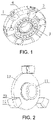
- a coupling for axle-suspended installation of a direct drive motor comprises a wheel axle side adapting flange 1 coaxially fixed with a wheel axle and a motor side adapting flange 2 coaxially fixed with the rotor shaft of a motor, and is characterized by further comprising an elastic support rotating assembly 3, wherein the elastic support rotating assembly 3 is radially connected between the wheel axle side adapting flange 1 and the motor side adapting flange 2 so that the wheel axle side adapting flange 1 and the motor side adapting flange 2 can be coaxially and rotatably connected and bear the weight of the motor along the radial direction through the elastic support rotating assembly 3, and the wheel axle side adapting flange 1 and the motor side adapting flange 2 are circumferentially elastically connected.
- the wheel axle side adapting flange 1 and the motor side adapting flange 2 are radially connected and circumferentially elastically connected through the elastic support rotating assembly 3, and the weight of the motor is borne through the elastic support rotating assembly 3 along the radial direction, which enhances the radial bearing capacity and has no influence on the torsional direction.
- the present invention solves the problem that the existing coupling has small radial bearing capacity and thus cannot be suitable for axle-suspended installation of a direct drive motor, enhances the radial bearing capacity of the coupling through the elastic support rotating assembly 3, ensures the radial damping effect through the elastic support rotating assembly 3, and can obtain better damping buffering effects while achieving great radial bearing capacity.
- the wheel axle side adapting flange 1 and the motor side adapting flange 2 are circumferentially elastically connected, and the circumferential elastic connection of the two flanges is used for damping buffering in the torsional direction, which solves the problem that it is difficult for the existing coupling to take into account bearing and damping buffering in two directions at the same time by the rubber elastomers.
- the elastic support rotating assembly is used to bear the weight of the motor and mitigate radial vibration
- circumferential elastic connection is used to reduce vibration in the torsional direction so that bearing and damping buffering of the coupling in radial and circumferential directions are set separately and do not interfere with each other, thus reducing system failure risks, extending the service life of metal-rubber parts and improving the use reliability of the coupling.
- the elastic support rotating assembly 3 is radially connected between the wheel axle side adapting flange 1 and the motor side adapting flange 2, and can radially position the wheel axle side adapting flange 1 and the motor side adapting flange 2, which easily realizes the alignment connection of the wheel axle side adapting flange and the motor side adapting flange and enhances the installation reliability and convenience of the coupling.
- the wheel axle side adapting flange 1 comprises a wheel axle sleeve 11 sleeved on the wheel axle by interference fit, connecting blocks I 12 used for circumferential elastic connection with the motor side adapting flange 2, and a radial connecting ring 13, wherein the connecting blocks I 12 are uniformly distributed along the periphery of the wheel axle sleeve 11 and connected with the wheel axle sleeve 11 through the radial connecting ring 13.
- the wheel axle sleeve 11 is used for connection with the wheel axle and radially connected with the motor side adapting flange 2 so that the wheel axle side adapting flange 1 and the motor side adapting flange 2 are coaxially connected.
- the connecting blocks I 12 are circumferentially elastically connected with the motor side adapting flange 2 and have simple structure so that radial connection and circumferential connection of the wheel axle side adapting flange 1 are easy to realize.
- the motor side adapting flange 2 comprises a connecting cylinder 21 coaxially and fixedly connected with the rotor shaft of the motor and connecting blocks II 22 used for circumferential elastic connection with the wheel axle side adapting flange 1, wherein the connecting blocks II 22 are fixed on the periphery of the connecting cylinder 21 and uniformly distributed on the periphery of the connecting cylinder 21 in one-to-one correspondence to the connecting blocks I 12, and the connecting blocks II 22 and the corresponding connecting blocks I 12 are circumferentially separated and elastically connected.
- the connecting cylinder 21 is coaxially connected with the rotor shaft of the motor, and the connecting blocks II 22 are circumferentially elastically connected with the connecting blocks I 12 so that the wheel axle side adapting flange 1 and the motor side adapting flange 2 are circumferentially elastically connected.
- the connecting blocks II 22 and the corresponding connecting blocks I 12 are elastically connected through metal-rubber parts 4, and the metal-rubber parts 4 are circumferentially compressed between the connecting blocks II 22 and the corresponding connecting blocks I 12.
- the metal-rubber parts 4 are compressed between the connecting blocks II 22 and the connecting blocks 12 to provide circumferential elasticity for torsion of the coupling.
- the metal-rubber parts 4 are unstressed, thus reducing the creeping and aging degree of the rubber.
- the metal-rubber parts 4 are only subjected to extrusion force rather than shear force so that the creep of the rubber is reduced, thus reducing system failure risks, extending the service life of metal-rubber parts and improving the use reliability of the coupling.
- the metal-rubber parts 4 comprise arc-shaped rubber blocks 41 and metal connectors 42 vulcanized and bonded on both arc-shaped ends of the rubber blocks 41, the connecting blocks I 12 and the connecting blocks II 22 are respectively axially positioned and fixedly connected with the metal connectors 42 through bolts, and the rubber blocks 41 are circumferentially arranged and compressed between two metal connectors 42.
- the metal connectors 42 are respectively connected with the connecting blocks I 12 and the connecting blocks II 22 to ensure the reliability of the connecting structure between the metal-rubber parts 4 and the wheel axle side adapting flange 1 and the motor side adapting flange 2.
- the rubber blocks 41 are vulcanized between two metal connectors 42 to provide circumferential elasticity.
- the circumferential stiffness of the coupling can be changed by changing the initial stiffness of the rubber blocks 41 so as to enable the coupling to meet different damping buffering requirements.
- the rubber blocks 41 are unstressed, thus reducing the creeping and aging degree of the rubber blocks 41.
- the rubber blocks 41 are only subjected to extrusion force rather than shear force so that the creep of the rubber blocks 41 is reduced, thus reducing system failure risks, extending the service life of metal-rubber parts and improving the use reliability of the coupling.
- the metal connectors 42 are in right-angled fit and contact with the connecting blocks I 12 and the connecting blocks II 22, the metal connectors 42 are provided with radial bulges 42.1, the connecting blocks I 12 and the connecting blocks II 22 are respectively provided with radial grooves 23 matched with the radial bulges 42.1, the radial grooves 23 are matched with the radial bulges 42.1 to axially position the metal connectors 42 respectively with the connecting blocks I 12 and the connecting blocks II 22, and partition plates 43 arranged radially are vulcanized in the rubber blocks 41. As shown in figures, the connecting blocks I 12 and the connecting blocks II 22 are respectively provided with radial grooves 23, while the metal connectors 42 are respectively provided with radial bulges 42.1.
- the radial bulges 42.1 are aligned with the radial grooves 23, and the metal-rubber parts 4 are radially compressed between the connecting blocks I 12 and the connecting blocks II 22 so that the metal-rubber parts 4 are axially positioned with the connecting blocks I 12 and the connecting blocks II 22 and then fastened by bolts.
- the radial bulges 42.1 are matched with the radial grooves 23, and the metal connectors 42 are in right-angled fit and contact with the connecting blocks I 12 and the connecting blocks II 22, which can ensure that the metal-rubber parts 4 can be quickly installed in place and the installation structure is firm and reliable, so as to improve the structure stability and reliability of the coupling.
- the partition plates 43 are arranged to improve the stiffness of the rubber blocks 41.
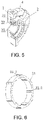
- the connecting cylinder 21 is sleeved with a radial support locating cylinder 24, the connecting blocks II 22 are arranged on the peripheral surface of the radial support cylinder 24 and integrated with the radial support cylinder 24, the axial height of the radial support locating cylinder 24 is greater than that of the connecting cylinder 21, and an elastic supporting assembly 3 is coaxially installed in the inner cavity of the radial support locating cylinder 24 and sleeved on the wheel axle sleeve 11.
- the radial support locating cylinder 24 is used for positioning the elastic support rotating assembly 3, the elastic support rotating assembly 3 is positioned between the wheel axle sleeve 11 and the radial support locating cylinder 24, and the axial height of the radial support locating cylinder 24 is greater than that of the connecting cylinder 21 so that the inner cavity of the radial support locating cylinder 24 has space for installing the support rotating assembly 3, and the installation of the support rotating assembly 3 is convenient and simple, which can effectively improve the assembly efficiency of the coupling.
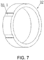
- the elastic supporting assembly 3 comprises an elastic support cylinder 31 installed in the inner cavity of the radial support locating cylinder 24 by circumferential location fit, a bearing pedestal 32 installed in the inner cavity of the elastic support cylinder 31 by circumferential location fit and a bearing 33 compressed in the bearing pedestal 32, wherein the inner ring of the bearing 33 is sleeved on the wheel axle sleeve 11.
- the elastic support cylinder 31, the bearing pedestal 32 and the bearing 33 are sleeved from outside to inside in sequence, and the elastic support cylinder 31 is circumferentially positioned in the inner cavity of the radial support locating cylinder 24 to ensure that the elastic supporting assembly 3 can rotate with the rotation of the motor side adapting flange 2.
- the arrangement of the bearing 33 enables the motor side adapting flange 2 and the wheel axle side adapting flange 1 to rotate relatively. Because the wheel axle side adapting flange 1 and the motor side adapting flange 2 can rotate relatively to facilitate installation of the metal-rubber parts 4, only the last metal-rubber part needs to be pre-compressed in the installation process of the plurality of metal-rubber parts 4. After installation, the pre-compression of each metal-rubber part can be realized through circumferential elastic stability. The installation process is convenient and simple, and the metal-rubber parts can be installed and removed separately, which is convenient for maintenance and replacement.
- the outer wall of the elastic support cylinder 31 is provided with axial locating bulges I 31.1
- the inner wall of the radial support locating cylinder 24 is provided with axial grooves I 24.1 matched with the locating bulges I 31.1
- the inner wall of the elastic support cylinder 31 is provided with axial locating bulges II 31.2
- the bearing pedestal 32 is provided with axial grooves II 32.1 matched with the locating bulges II 31.2
- the locating bulges I 31.1 are matched with the axial grooves I 24.1 to make the elastic support cylinder 31 in circumferential location fit with the radial support locating cylinder 24
- the locating bulges II 31.2 are matched with the axial grooves II 32.1 to make the elastic support cylinder 31 in circumferential location fit with the bearing pedestal 32
- the locating bulges I 31.1 and the locating bulges II 31.2 are uniformly and alternately distributed along the circumferential direction of the elastic support cylinder 31, and the elastic support cylinder 31 is made
- the outer wall of the elastic support cylinder 31 is provided with locating bulges I 31.1
- the inner wall is provided with locating bulges II 31.2
- the locating bulges I 31.1 and the locating bulges II 31.2 are uniformly and alternately distributed, i.e., one locating bulge II 31.2 is arranged between two locating bulges I 31.1, one locating bulge 131.1 is also arranged between two locating bulges II 31.2
- the distance between the adjacent locating bulges I is equal to that between the adjacent locating bulges II
- an elastic support beam is formed between the adjacent locating bulge I and locating bulge II
- each locating bulge I or locating bulge II is located between two elastic support beams to effectively bear the weight of the motor so as to ensure that the coupling has greater radial bearing capacity.
- the elastic support cylinder 31 is made of spring steel and has certain elastic buffering capacity so as to effectively reduce the radial vibration of the wheel axle side adapting flange 1 and the motor side adapting flange 2 and obtain better damping buffering effects while achieving great radial bearing capacity.
- the initial stiffness of circumferential elastic connection between the wheel axle side adapting flange 1 and the motor side adapting flange 2 is designed according to the damping buffering requirements of the coupling for axle-suspended installation of a direct drive motor in the torsional direction in use
- the stiffness of the elastic support rotating assembly 3 is designed according to the radial bearing and damping requirements of the coupling for axle-suspended installation of a direct drive motor in use.
- the design of the initial stiffness of circumferential elastic connection between the wheel axle side adapting flange 1 and the motor side adapting flange 2 refers to the design of the quantity and initial stiffness value of the metal-rubber parts 4, while the design of the initial stiffness value of the metal-rubber parts 4 refers to the design of the circumferential thickness, material and pre-compression amount of the rubber blocks 41 and the addition of partition plates 43 to the rubber blocks 41 according to the stiffness requirements.
- the design of the stiffness of the elastic support rotating assembly 3 refers to the design of the structure, axial height, radial thickness and material of the elastic support cylinder 31 in the support rotating assembly, while the design of the structure of the elastic support cylinder 31 refers to the determination of the quantity of the locating bulges I 31.1 and the quantity of the locating bulges II 31.2.
- the initial stiffness of circumferential elastic connection between the wheel axle side adapting flange 1 and the motor side adapting flange 2 is designed according to the damping buffering requirements of the coupling in the torsional direction
- the stiffness of the elastic support rotating assembly 3 is designed according to the radial bearing and damping requirements of the coupling, which meets different bearing and damping requirements of the coupling in radial and torsional directions, effectively improves the damping buffering effects of the coupling, enhances the radial bearing capacity of the coupling, improves the reliability of the coupling, and extends the service life of the coupling.
Landscapes
- Engineering & Computer Science (AREA)
- General Engineering & Computer Science (AREA)
- Mechanical Engineering (AREA)
- Power Engineering (AREA)
- Chemical & Material Sciences (AREA)
- Combustion & Propulsion (AREA)
- Transportation (AREA)
- Vibration Prevention Devices (AREA)
- Arrangement Or Mounting Of Propulsion Units For Vehicles (AREA)
Applications Claiming Priority (2)
| Application Number | Priority Date | Filing Date | Title |
|---|---|---|---|
| CN201911155297.8A CN110671436B (zh) | 2019-11-22 | 2019-11-22 | 轴悬式安装直驱电机用联轴器及其刚度设计方法 |
| PCT/CN2020/127764 WO2021098549A1 (fr) | 2019-11-22 | 2020-11-10 | Accouplement pour moteur à entraînement direct suspendu par le nez et procédé de conception de la rigidité de celui-ci |
Publications (4)
| Publication Number | Publication Date |
|---|---|
| EP4063224A1 true EP4063224A1 (fr) | 2022-09-28 |
| EP4063224A4 EP4063224A4 (fr) | 2024-01-03 |
| EP4063224B1 EP4063224B1 (fr) | 2025-08-13 |
| EP4063224C0 EP4063224C0 (fr) | 2025-08-13 |
Family
ID=69088124
Family Applications (1)
| Application Number | Title | Priority Date | Filing Date |
|---|---|---|---|
| EP20890668.5A Active EP4063224B1 (fr) | 2019-11-22 | 2020-11-10 | Accouplement pour moteur à entraînement direct suspendu par le nez et procédé de conception de la rigidité de celui-ci |
Country Status (4)
| Country | Link |
|---|---|
| US (1) | US12122430B2 (fr) |
| EP (1) | EP4063224B1 (fr) |
| CN (1) | CN110671436B (fr) |
| WO (1) | WO2021098549A1 (fr) |
Families Citing this family (5)
| Publication number | Priority date | Publication date | Assignee | Title |
|---|---|---|---|---|
| CN110671436B (zh) * | 2019-11-22 | 2021-10-26 | 株洲时代新材料科技股份有限公司 | 轴悬式安装直驱电机用联轴器及其刚度设计方法 |
| FR3108803B1 (fr) * | 2020-03-25 | 2022-03-11 | Novares France | Rotor pour moteur électrique intégrant des éléments d'absorption acoustique |
| CN112268072B (zh) * | 2020-10-27 | 2021-11-23 | 东风越野车有限公司 | 一种多级可变扭转刚度的柔性扭矩传递装置 |
| CN112855789B (zh) * | 2021-01-05 | 2022-03-22 | 株洲时代新材料科技股份有限公司 | 一种用于直驱电机的联轴器装置 |
| CN119527355B (zh) * | 2023-08-30 | 2026-04-21 | 中车青岛四方机车车辆股份有限公司 | 轴端传动装置、轮对及转向架 |
Family Cites Families (18)
| Publication number | Priority date | Publication date | Assignee | Title |
|---|---|---|---|---|
| US1561476A (en) * | 1923-04-02 | 1925-11-17 | Int Motor Co | Torque-cushioning device |
| US1679992A (en) * | 1927-02-23 | 1928-08-07 | Gen Motors Res Corp | Universal joint with rubber inserts |
| DE580482C (de) * | 1931-10-17 | 1933-07-12 | Kirchbach Sche Werke Kirchbach | Gelenkkupplung fuer Kraftfahrzeuge |
| US3859929A (en) * | 1973-09-06 | 1975-01-14 | Rheinstahl Ag | Resilient double axle railway car drive |
| DE2438088C3 (de) * | 1974-08-08 | 1988-03-24 | BBC Brown Boveri AG, 6800 Mannheim | Kraftübertragungseinrichtung zwischen Hohlwelle und Treibrad eines elektrischen Schienentriebfahrzeuges |
| DE3843496C1 (fr) * | 1988-12-23 | 1990-04-26 | Carl Hurth Maschinen- Und Zahnradfabrik Gmbh & Co, 8000 Muenchen, De | |
| DE3906201C2 (de) * | 1989-02-28 | 1995-01-12 | Freudenberg Carl Fa | Drehelastische Klauenkupplung |
| EP0626523B1 (fr) * | 1993-03-26 | 1996-12-11 | CENTA-ANTRIEBE KIRSCHEY GmbH | Accouplement élastique étagé à deux niveaux |
| US5950778A (en) * | 1996-10-31 | 1999-09-14 | Eastman Kodak Company | Vibration isolation drive coupling |
| JP4243149B2 (ja) * | 2003-08-11 | 2009-03-25 | 東日本旅客鉄道株式会社 | 車両用主電動機の継手型駆動装置 |
| WO2006051046A1 (fr) | 2004-11-11 | 2006-05-18 | Siemens Aktiengesellschaft | Entrainement direct a ressort semi-elliptique pour vehicule ferroviaire |
| JP5048804B2 (ja) * | 2010-03-31 | 2012-10-17 | 日立オートモティブシステムズ株式会社 | パワーステアリング装置 |
| JP5798946B2 (ja) * | 2012-02-24 | 2015-10-21 | カヤバ工業株式会社 | 電動パワーステアリング装置、及びそれに用いられる軸連結器 |
| CN205226110U (zh) * | 2015-12-28 | 2016-05-11 | 中国重汽集团济南动力有限公司 | 一种橡胶联轴器 |
| CN106364496B (zh) | 2016-09-30 | 2019-02-26 | 中车南京浦镇车辆有限公司 | 一种抱轴安装电机用弹性悬挂装置 |
| CN108674173B (zh) * | 2018-07-12 | 2024-03-29 | 秦广 | 混合动力汽车轮毂电机驱动总成 |
| CN110027575A (zh) * | 2019-04-03 | 2019-07-19 | 株洲时代新材料科技股份有限公司 | 一种连接器 |
| CN110671436B (zh) * | 2019-11-22 | 2021-10-26 | 株洲时代新材料科技股份有限公司 | 轴悬式安装直驱电机用联轴器及其刚度设计方法 |
-
2019
- 2019-11-22 CN CN201911155297.8A patent/CN110671436B/zh active Active
-
2020
- 2020-11-10 EP EP20890668.5A patent/EP4063224B1/fr active Active
- 2020-11-10 WO PCT/CN2020/127764 patent/WO2021098549A1/fr not_active Ceased
- 2020-11-10 US US17/624,352 patent/US12122430B2/en active Active
Also Published As
| Publication number | Publication date |
|---|---|
| EP4063224A4 (fr) | 2024-01-03 |
| EP4063224B1 (fr) | 2025-08-13 |
| CN110671436B (zh) | 2021-10-26 |
| EP4063224C0 (fr) | 2025-08-13 |
| CN110671436A (zh) | 2020-01-10 |
| WO2021098549A1 (fr) | 2021-05-27 |
| US20220348235A1 (en) | 2022-11-03 |
| US12122430B2 (en) | 2024-10-22 |
Similar Documents
| Publication | Publication Date | Title |
|---|---|---|
| US12122430B2 (en) | Coupling for axle-suspended installation of direct drive motor and stiffness design method therefor | |
| US11214136B2 (en) | Cradle assembly for an electric axle assembly | |
| CN102700372A (zh) | 高稳定性电动轮毂 | |
| CN106364496B (zh) | 一种抱轴安装电机用弹性悬挂装置 | |
| CN104632918A (zh) | 轨道车辆的双扭力耦联器和用于装配双扭力耦联器的方法 | |
| CN109424696B (zh) | 扭转减振器及使用该扭转减振器的车辆 | |
| CN109849589B (zh) | 一种具有整体式驱动后桥的电动汽车后驱结构 | |
| CN110962502B (zh) | 轨道车辆用弹性车轮及其使用方法、独立轮对 | |
| CN214146326U (zh) | 一种挖掘机机械臂的连接用联轴器 | |
| CN107387743B (zh) | 一种大型风电齿轮箱行星架轴承布置结构 | |
| CN201396382Y (zh) | 一种弹性联轴器 | |
| CN202107972U (zh) | 振动压路机的振动轮和振动压路机 | |
| CN201568317U (zh) | 核三级重要厂用水泵 | |
| CN110027575A (zh) | 一种连接器 | |
| CN203438852U (zh) | 电机动力输出结构及应用其的电动汽车 | |
| RU2297935C2 (ru) | Привод колесной пары локомотива | |
| CN114412932B (zh) | 一种风力发电机组低速弹性联轴器 | |
| CN215293331U (zh) | 整体式离合器从动盘波形片 | |
| CN202144179U (zh) | 车轮组装置 | |
| CN220168354U (zh) | 汽车减振器用滑片轴承 | |
| CN114337045A (zh) | 一种可实现轴承防护的电机 | |
| CN222084986U (zh) | 一种方便扩展的汽车传动轴 | |
| CN210211909U (zh) | 一种分体式电动车后桥 | |
| CN216555035U (zh) | 一种轮胎式联轴器 | |
| CN209943363U (zh) | 一种连接器 |
Legal Events
| Date | Code | Title | Description |
|---|---|---|---|
| STAA | Information on the status of an ep patent application or granted ep patent |
Free format text: STATUS: THE INTERNATIONAL PUBLICATION HAS BEEN MADE |
|
| PUAI | Public reference made under article 153(3) epc to a published international application that has entered the european phase |
Free format text: ORIGINAL CODE: 0009012 |
|
| STAA | Information on the status of an ep patent application or granted ep patent |
Free format text: STATUS: REQUEST FOR EXAMINATION WAS MADE |
|
| 17P | Request for examination filed |
Effective date: 20220321 |
|
| AK | Designated contracting states |
Kind code of ref document: A1 Designated state(s): AL AT BE BG CH CY CZ DE DK EE ES FI FR GB GR HR HU IE IS IT LI LT LU LV MC MK MT NL NO PL PT RO RS SE SI SK SM TR |
|
| DAV | Request for validation of the european patent (deleted) | ||
| DAX | Request for extension of the european patent (deleted) | ||
| A4 | Supplementary search report drawn up and despatched |
Effective date: 20231205 |
|
| RIC1 | Information provided on ipc code assigned before grant |
Ipc: B61C 9/38 20060101ALI20231129BHEP Ipc: B61C 9/44 20060101AFI20231129BHEP |
|
| GRAP | Despatch of communication of intention to grant a patent |
Free format text: ORIGINAL CODE: EPIDOSNIGR1 |
|
| STAA | Information on the status of an ep patent application or granted ep patent |
Free format text: STATUS: GRANT OF PATENT IS INTENDED |
|
| INTG | Intention to grant announced |
Effective date: 20250523 |
|
| GRAS | Grant fee paid |
Free format text: ORIGINAL CODE: EPIDOSNIGR3 |
|
| GRAA | (expected) grant |
Free format text: ORIGINAL CODE: 0009210 |
|
| STAA | Information on the status of an ep patent application or granted ep patent |
Free format text: STATUS: THE PATENT HAS BEEN GRANTED |
|
| AK | Designated contracting states |
Kind code of ref document: B1 Designated state(s): AL AT BE BG CH CY CZ DE DK EE ES FI FR GB GR HR HU IE IS IT LI LT LU LV MC MK MT NL NO PL PT RO RS SE SI SK SM TR |
|
| REG | Reference to a national code |
Ref country code: GB Ref legal event code: FG4D |
|
| REG | Reference to a national code |
Ref country code: CH Ref legal event code: EP |
|
| REG | Reference to a national code |
Ref country code: IE Ref legal event code: FG4D |
|
| U01 | Request for unitary effect filed |
Effective date: 20250813 |
|
| U07 | Unitary effect registered |
Designated state(s): AT BE BG DE DK EE FI FR IT LT LU LV MT NL PT RO SE SI Effective date: 20250820 |
|
| PGFP | Annual fee paid to national office [announced via postgrant information from national office to epo] |
Ref country code: GB Payment date: 20250912 Year of fee payment: 6 |
|
| U20 | Renewal fee for the european patent with unitary effect paid |
Year of fee payment: 6 Effective date: 20250919 |
|
| PG25 | Lapsed in a contracting state [announced via postgrant information from national office to epo] |
Ref country code: IS Free format text: LAPSE BECAUSE OF FAILURE TO SUBMIT A TRANSLATION OF THE DESCRIPTION OR TO PAY THE FEE WITHIN THE PRESCRIBED TIME-LIMIT Effective date: 20251213 |
|
| PG25 | Lapsed in a contracting state [announced via postgrant information from national office to epo] |
Ref country code: NO Free format text: LAPSE BECAUSE OF FAILURE TO SUBMIT A TRANSLATION OF THE DESCRIPTION OR TO PAY THE FEE WITHIN THE PRESCRIBED TIME-LIMIT Effective date: 20251113 |
|
| PG25 | Lapsed in a contracting state [announced via postgrant information from national office to epo] |
Ref country code: HR Free format text: LAPSE BECAUSE OF FAILURE TO SUBMIT A TRANSLATION OF THE DESCRIPTION OR TO PAY THE FEE WITHIN THE PRESCRIBED TIME-LIMIT Effective date: 20250813 |
|
| PG25 | Lapsed in a contracting state [announced via postgrant information from national office to epo] |
Ref country code: GR Free format text: LAPSE BECAUSE OF FAILURE TO SUBMIT A TRANSLATION OF THE DESCRIPTION OR TO PAY THE FEE WITHIN THE PRESCRIBED TIME-LIMIT Effective date: 20251114 |
|
| PG25 | Lapsed in a contracting state [announced via postgrant information from national office to epo] |
Ref country code: PL Free format text: LAPSE BECAUSE OF FAILURE TO SUBMIT A TRANSLATION OF THE DESCRIPTION OR TO PAY THE FEE WITHIN THE PRESCRIBED TIME-LIMIT Effective date: 20250813 |
|
| PG25 | Lapsed in a contracting state [announced via postgrant information from national office to epo] |
Ref country code: RS Free format text: LAPSE BECAUSE OF FAILURE TO SUBMIT A TRANSLATION OF THE DESCRIPTION OR TO PAY THE FEE WITHIN THE PRESCRIBED TIME-LIMIT Effective date: 20251113 |
|
| PG25 | Lapsed in a contracting state [announced via postgrant information from national office to epo] |
Ref country code: ES Free format text: LAPSE BECAUSE OF FAILURE TO SUBMIT A TRANSLATION OF THE DESCRIPTION OR TO PAY THE FEE WITHIN THE PRESCRIBED TIME-LIMIT Effective date: 20250813 |
|
| PG25 | Lapsed in a contracting state [announced via postgrant information from national office to epo] |
Ref country code: SM Free format text: LAPSE BECAUSE OF FAILURE TO SUBMIT A TRANSLATION OF THE DESCRIPTION OR TO PAY THE FEE WITHIN THE PRESCRIBED TIME-LIMIT Effective date: 20250813 |
|
| PG25 | Lapsed in a contracting state [announced via postgrant information from national office to epo] |
Ref country code: CZ Free format text: LAPSE BECAUSE OF FAILURE TO SUBMIT A TRANSLATION OF THE DESCRIPTION OR TO PAY THE FEE WITHIN THE PRESCRIBED TIME-LIMIT Effective date: 20250813 |
|
| PG25 | Lapsed in a contracting state [announced via postgrant information from national office to epo] |
Ref country code: SK Free format text: LAPSE BECAUSE OF FAILURE TO SUBMIT A TRANSLATION OF THE DESCRIPTION OR TO PAY THE FEE WITHIN THE PRESCRIBED TIME-LIMIT Effective date: 20250813 |