EP4063236B1 - Chariot - Google Patents
Chariot Download PDFInfo
- Publication number
- EP4063236B1 EP4063236B1 EP22162513.0A EP22162513A EP4063236B1 EP 4063236 B1 EP4063236 B1 EP 4063236B1 EP 22162513 A EP22162513 A EP 22162513A EP 4063236 B1 EP4063236 B1 EP 4063236B1
- Authority
- EP
- European Patent Office
- Prior art keywords
- dolly
- auto
- tow bar
- release mechanism
- brake
- Prior art date
- Legal status (The legal status is an assumption and is not a legal conclusion. Google has not performed a legal analysis and makes no representation as to the accuracy of the status listed.)
- Active
Links
Images

Classifications
-
- B—PERFORMING OPERATIONS; TRANSPORTING
- B62—LAND VEHICLES FOR TRAVELLING OTHERWISE THAN ON RAILS
- B62B—HAND-PROPELLED VEHICLES, e.g. HAND CARTS OR PERAMBULATORS; SLEDGES
- B62B5/00—Accessories or details specially adapted for hand carts
- B62B5/04—Braking mechanisms; Locking devices against movement
- B62B5/0438—Braking mechanisms; Locking devices against movement hand operated
- B62B5/0447—Braking mechanisms; Locking devices against movement hand operated using elements cooperating with a handle bar
-
- B—PERFORMING OPERATIONS; TRANSPORTING
- B62—LAND VEHICLES FOR TRAVELLING OTHERWISE THAN ON RAILS
- B62B—HAND-PROPELLED VEHICLES, e.g. HAND CARTS OR PERAMBULATORS; SLEDGES
- B62B3/00—Hand carts having more than one axis carrying transport wheels; Steering devices therefor; Equipment therefor
-
- B—PERFORMING OPERATIONS; TRANSPORTING
- B62—LAND VEHICLES FOR TRAVELLING OTHERWISE THAN ON RAILS
- B62B—HAND-PROPELLED VEHICLES, e.g. HAND CARTS OR PERAMBULATORS; SLEDGES
- B62B5/00—Accessories or details specially adapted for hand carts
- B62B5/04—Braking mechanisms; Locking devices against movement
- B62B5/0404—Braking mechanisms; Locking devices against movement automatic
-
- B—PERFORMING OPERATIONS; TRANSPORTING
- B60—VEHICLES IN GENERAL
- B60D—VEHICLE CONNECTIONS
- B60D1/00—Traction couplings; Hitches; Draw-gear; Towing devices
-
- B—PERFORMING OPERATIONS; TRANSPORTING
- B60—VEHICLES IN GENERAL
- B60T—VEHICLE BRAKE CONTROL SYSTEMS OR PARTS THEREOF; BRAKE CONTROL SYSTEMS OR PARTS THEREOF, IN GENERAL; ARRANGEMENT OF BRAKING ELEMENTS ON VEHICLES IN GENERAL; PORTABLE DEVICES FOR PREVENTING UNWANTED MOVEMENT OF VEHICLES; VEHICLE MODIFICATIONS TO FACILITATE COOLING OF BRAKES
- B60T11/00—Transmitting braking action from initiating means to ultimate brake actuator without power assistance or drive or where such assistance or drive is irrelevant
- B60T11/04—Transmitting braking action from initiating means to ultimate brake actuator without power assistance or drive or where such assistance or drive is irrelevant transmitting mechanically
- B60T11/046—Using cables
-
- B—PERFORMING OPERATIONS; TRANSPORTING
- B60—VEHICLES IN GENERAL
- B60T—VEHICLE BRAKE CONTROL SYSTEMS OR PARTS THEREOF; BRAKE CONTROL SYSTEMS OR PARTS THEREOF, IN GENERAL; ARRANGEMENT OF BRAKING ELEMENTS ON VEHICLES IN GENERAL; PORTABLE DEVICES FOR PREVENTING UNWANTED MOVEMENT OF VEHICLES; VEHICLE MODIFICATIONS TO FACILITATE COOLING OF BRAKES
- B60T7/00—Brake-action initiating means
- B60T7/12—Brake-action initiating means for automatic initiation; for initiation not subject to will of driver or passenger
- B60T7/20—Brake-action initiating means for automatic initiation; for initiation not subject to will of driver or passenger specially for trailers, e.g. in case of uncoupling of or overrunning by trailer
-
- B—PERFORMING OPERATIONS; TRANSPORTING
- B62—LAND VEHICLES FOR TRAVELLING OTHERWISE THAN ON RAILS
- B62B—HAND-PROPELLED VEHICLES, e.g. HAND CARTS OR PERAMBULATORS; SLEDGES
- B62B3/00—Hand carts having more than one axis carrying transport wheels; Steering devices therefor; Equipment therefor
- B62B3/001—Steering devices
-
- B—PERFORMING OPERATIONS; TRANSPORTING
- B62—LAND VEHICLES FOR TRAVELLING OTHERWISE THAN ON RAILS
- B62B—HAND-PROPELLED VEHICLES, e.g. HAND CARTS OR PERAMBULATORS; SLEDGES
- B62B5/00—Accessories or details specially adapted for hand carts
- B62B5/0026—Propulsion aids
- B62B5/0079—Towing by connecting to another vehicle
-
- B—PERFORMING OPERATIONS; TRANSPORTING
- B62—LAND VEHICLES FOR TRAVELLING OTHERWISE THAN ON RAILS
- B62B—HAND-PROPELLED VEHICLES, e.g. HAND CARTS OR PERAMBULATORS; SLEDGES
- B62B5/00—Accessories or details specially adapted for hand carts
- B62B5/04—Braking mechanisms; Locking devices against movement
- B62B5/0438—Braking mechanisms; Locking devices against movement hand operated
- B62B5/0442—Braking mechanisms; Locking devices against movement hand operated using a handle bar alone
-
- B—PERFORMING OPERATIONS; TRANSPORTING
- B62—LAND VEHICLES FOR TRAVELLING OTHERWISE THAN ON RAILS
- B62B—HAND-PROPELLED VEHICLES, e.g. HAND CARTS OR PERAMBULATORS; SLEDGES
- B62B2207/00—Joining hand-propelled vehicles or sledges together
-
- B—PERFORMING OPERATIONS; TRANSPORTING
- B62—LAND VEHICLES FOR TRAVELLING OTHERWISE THAN ON RAILS
- B62B—HAND-PROPELLED VEHICLES, e.g. HAND CARTS OR PERAMBULATORS; SLEDGES
- B62B5/00—Accessories or details specially adapted for hand carts
- B62B5/04—Braking mechanisms; Locking devices against movement
- B62B5/0404—Braking mechanisms; Locking devices against movement automatic
- B62B5/0414—Braking mechanisms; Locking devices against movement automatic dead man's brakes
Definitions
- the present invention relates to logistics equipment, in particular to wheeled load carriers. More specifically, the invention relates to a dolly with a braking mechanism.
- Dollies for distributing products from one location to another are common in warehouses and other commercial facilities.
- a dolly is also referred to as a "platform truck”, “platform cart”, “push dolly”, “push cart”, or “push cart dolly”.
- Dollies may have braking mechanisms to allow for convenient user control while transporting.
- Some varieties of dollies are towed by a driving vehicle where multiple dollies can be hitched together at the front and back ends. These dollies capable of being hitched and towed, are often unhitched from one another for several reasons, such as less cargo required in the group of towed dollies and maintenance. When these dollies do not require towing they are unhitched and consequently able to move freely if pushed. The ability for the dolly to move once unhitched can cause the dolly to solely move on a sloped surface or be moved when bumped into. In other words, these dollies can lead to unsafe working environments since they can cause injury and also damage surrounding items. Additionally, if dollies are unexpectedly moved, there is a risk that the loaded item can be damaged by a sudden crash or by falling.
- Braking mechanisms have been developed to address this issue.
- Conventional braking mechanism are operated with foot levers for selectively applying and releasing the brake.
- DE 102013215689 A1 and US 4986596 A disclose a logistics dolly with a folding tow bar, which engages a brake, when turned into an upright parking orientation, and which releases a brake, when turned into a horizontal towing orientation.
- WO 03/057542 A2 discloses a logistics dolly with a steering handle, which can be turned between a park position, in which a wheel is locked by means of a brake rod connected to the steering handle, and a diagonal operational position.
- the dolly features a tow bar that automatically releases a braking mechanism when the dolly is unhitched, i.e. when the dolly is not towed.
- the dolly is defined by the hereto appended independent claim.
- a dolly featuring at least one wheel, an auto-engaging brake, and a release mechanism for selectively manipulating the auto-engaging brake from an applied state to a released state.
- the dolly further includes a tow bar which is connected to the release mechanism for operating the auto-engaging brake between the applied and released state.
- the auto-engaging brake ensures that the dolly is stationary when not in use or not towed.
- the brake is automatically released, when the tow bar is lowered into towing configuration. This process is achieved without the user conducting an extra step to manipulate the brake into an applied state.
- the tow bar therefore, ensures that the dolly does not unexpectedly move on a surface, particularly a sloped surface. Achieving a stationary dolly ensures safety in the environment surrounding the dolly. Workers who handle the dollies are not susceptible to an injury caused by a dolly unexpectedly moving on a sloped surface. Additionally, the dolly is likely not to damage surrounding items due to a sloped surface, therefore, repairs and costs can be avoided.
- the tow bar may automatically retreat to a storing configuration immediately after detachment, and the brake is automatically applied.
- a dolly refers to a vehicle suitable for transporting goods. Such dollies may be linked to one another to create a train of dollies for transporting a larger number of goods.
- the proposed construction is based on the idea of providing a means to automatically apply a brake immediately after a dolly is no longer hitched.
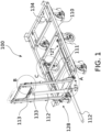
- FIGURE 1 illustrates a general view of a dolly 100 according to an exemplary embodiment.
- the dolly has a frame 110 having a front side, a back side, a right side, a left side, and an upper section.
- the frame 110 is made of welded steel.
- the dolly 100 has a tow bar 112 which has a first end pivotally connected to the front side of the frame 110.
- FIGURE 1 illustrates two orientations of the tow bar 112, namely a generally vertical storage orientation and a generally horizontal or non-vertical towing orientation.
- the storage orientation is illustrated in solid lines, while the towing orientation is illustrated in dashed lines.
- the tow bar 112 has a second end opposing the first end, where the second end comprises of a first hitch counterpart 133.
- the first hitch counterpart 133 is configured to connect to a second hitch counterpart 134 of another dolly.
- the first hitch counterpart 133 is shown as a female, and the second hitch counterpart 134 is shown as a male.
- the counterparts 133, 134 are designed to allow for rotation about a vertical rotation axis.
- the dolly has at least one wheel 111.
- the frame has six wheels, two wheels which are fixed and do not swivel, and four wheels which swivel.
- the dolly 100 has a handle 113 connected to an upright section extending from the frame 110.
- the dolly 100 has a release mechanism 121 which is mounted to the frame 110 and connected to the tow bar 112 and, optionally, to the handle 113.
- the tow bar 112 acts as a primary input device for the release mechanism 121, whereas the handle 113 is a secondary input device.
- the release mechanism 121 acts on two different wheels 111.
- the release mechanism 121 is therefore divided into two branches 127, 128, namely a first branch 127 located on the right and a second branch 128 the left side of the frame 110.
- Each branch 127, 128 connects to a wheel 111.
- FIGURE 2 illustrates detail view A of FIGURE 1 .
- the tow bar 112 is connected to a biasing mechanism 123.
- the tow bar 112 is connected to an axle 124 which shares an axis of rotation with the tow bar 112.
- a biasing mechanism 123 is connected to tow bar 112 and axle 124 to apply force on the tow bar 112 to rotate the tow bar 112 towards the vertical orientation.
- the axle 124 has a first end connected to the first branch 127 and a second end connected to the second branch 128. The first end of the axle 124 is opposite of the second end of the axle 124.
- a motion converter 125 is connected to the end of the axle 124, where the motion converter 125 is able to rotate at the same angular velocity as the axle 124.
- a second end of a transmission line 126 for the tow bar is connected to the motion converter 125, where the transmission line 126 is able to translate linearly.
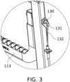
- FIGURE 3 illustrates detail view B of FIGURE 1 .
- a handle 113 is connected to a first end of a handle axle 130, where the handle 113 and handle axle 130 share an axis of rotation.
- a motion converter 131 is attached to a second end of the handle axle 130, which transmits rotation of the handle 113 to the motion converter 131.
- a second end of a transmission line 132 for the handle 113 is connected to the motion converter 131.
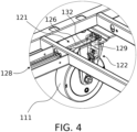
- FIGURE 4 illustrates detail view C of FIGURE 1 .
- the release mechanism 121 is divided into two branches 127,128, each branch comprising a transmission line running from the input device, i.e. tow bar or handle, to an auto-engaging brake 122.
- FIGURE 4 illustrates the branch 128 mounted on the left side of the frame 110.
- a first end of the transmission lines 126, 132 are connected to an impactor 129.
- the auto-engaging brake 122 comprises the impactor 129, in which the auto-engaging brake 122 comes in contact and releases contact with the wheel 111.
- FIGURE 4 reveals the impactor 129 in the applied state illustrated in solid lines, and reveals the impactor 129 in the released state illustrated in dashed lines.
- the impactor 129 is constructed as a rotatable lever which includes a mounting point for the transmission lines 126, 132.
- the transmission line 126, 132 may take the form of a cable. Accordingly, the brake end of the cable may be affixed to the free end of the brake lever.
- the auto-engaging brake 122 is integrated into the wheel 111.
- brake mechanisms are commercially available and known per se.
- One commercially available option is the "Dead man's brake” castor by Mahle.
- Such auto-engaging brakes are concealed under a cover of the brake so as to keep the brake mechanism protected from the elements.
- Such auto-engaging brakes are known to default into a braking state with aid of biasing devices incorporated into the mechanism. Accordingly, the brake must be separately released with aid of a brake lever, such as the illustrated impactor, for example.
- the counterparts are configured to allow for rotation between the tow bar 112 of one such dolly and the frame 110 of another such dolly about a vertical rotation axis.
- the first hitch counterpart 133 and the second hitch counterpart 134 of another dolly are connected when the tow bar 112 is in a horizontal orientation, which is a towing orientation.
- the tow bar 112 is configured to move from the storage orientation to the towing orientation. This process may be done by the user unhitching the hitch counterparts 133, 134.
- the release mechanism 121 can selectively manipulate the auto-engaging brake 122 to toggle between an applied state and a released state.
- the release mechanism 121 manipulates the auto-engaging brake 122 into the released state, i.e. the auto-engaging brake 122 does not prevent the wheel 111 from turning.
- the release mechanism 121 manipulates the auto-engaging brake 122 into the applied state, i.e. the auto-engaging brake 122 prevents the wheel 111 from turning.
- the biasing mechanism 123 seen in FIGURE 2 applies force on the tow bar 112 to automatically rotate the tow bar 112 from the towing orientation to the storage orientation when the first hitch counterpart 133 is no longer engaged to the second counterpart 134 of such dolly in series, i.e. when the first and second counterparts 133, 134 are unhitched.
- the function of the biasing mechanism is to automatically manipulate the auto-engaging brake 121 into the applied state immediately after a user disconnects the first and second counterparts 133, 134. This is convenient since the user does not take an extra step to apply the auto-engaging brakes 121 to the wheels 111.
- the motion converter 125 transmits rotational movement of the axle 124 to translation of the transmission line 126.
- the axle 124 and motion converter 125 rotate, which causes the transmission line 126 to translate in a linear direction.
- the transmission line 126 then manipulates the impactor 129 to be in the applied state or the released state.
- the motion converter 131 seen in FIGURE 3 is configured to transmit rotational movement of the handle axel 130 to translation of a transmission line 132.
- the transmission line 132 manipulates the impactor 129 and toggles the auto-engaging brake 121 between the applied and the released state.
- FIGURE 4 illustrates the branch 128 comprising of transmission lines 126, 127.
- the impactor 129 causes the auto-engaging brake 122 to impact or not impact the wheel 111.
- the auto-engaging brake 122 is applied to the wheel 111, i.e. the brake pad (not shown) auto-engaging brake 122 comes into contact with the wheel 111.
- the applied state is configured to prevent the wheel 111 from rotating, and therefore, prevent the dolly 100 from moving while in storage.
- the applied state of the impactor 129 is illustrated in solid lines in FIGURE 4 .
- the auto-engaging brake 122 is released.
- the released state is configured to allow the wheel 111 to rotate, and therefore, allow the dolly 100 to move while being towed.
- the released state of the impactor 129 is illustrated in dashed lines in FIGURE 4 . According to the illustrated embodiment, the impactor 129 turns between two positions which correspond to the released and applied states.
- the end result of moving the tow bar 112 into either the storage or the towing orientation is to apply the auto-engaging brake 122 onto the wheel 111 or release the auto-engaging brake 122 from the wheel 111.
- another embodiment comprises the frame 110, which may be configured to support a platform on top of itself.
- the frame 110 may be made of aluminum and may be assembled by fasteners.
- the frame 110 may have one wheel or a plurality of wheels.
- the frame 110 may have all fixed wheels, all swiveling wheels, or a combination of both types.
- the auto-engaging brake may be attached to swiveling and non-swiveling wheels.
- the frame 110 may exclude an upper section.
- the frame 110 may have two sides or more than two sides.
- the tow bar 112 may be connected to the frame 110 at the right side, the left side, the front side, the back side, a top side or a bottom side.
- the release mechanism 121 may be mounted only on one section or sides of the frame 110 or on many sections or sides of the frame 110.
- the release mechanism 121 is connected to the tow bar 112 and the handle 113.
- the dolly 100 has a first and a second hitch counterparts 133, 134, wherein the first hitch counterpart 133 may be a female or a male connection and the second hitch counterpart 134 may be a female or a male connection.
- the female connection may be a hole and the male connection may be a common male hitch connection as known in the art.
- the tow bar 112 may be moved from the vertical storage orientation to the horizontal orientation by hand of the user, or some manual action by the user. Alternatively, the tow bar 112 may be moved from the vertical storage orientation to the horizontal orientation by automation.
- the storage orientation, where the auto-engaging brake 122 is in the applied state may be at an angle to a vertical plane, i.e. the storage orientation may be slightly non-vertical.
- the towing orientation, where the auto-engaging brake 122 is in the released state may be at an angle to a horizontal plane, i.e. the towing orientation may be slightly non-horizontal.
- the biasing mechanism guides the tow bar 112 from the horizontal towing orientation to the vertical storage orientation soon after the tow bar 112 is disconnected from another dolly, specifically, when the first hitch counterpart 133 detaches from the second hitch counterpart 134 of another dolly.
- the biasing mechanism may be a spring or a type of damper, such as a spring, pneumatic or hydraulic damper.
- the dolly 100 may comprise more than two branches. Additionally, the branch may have more than one wheel. Each branch may comprise only one transmission line or may comprise a plurality of transmission lines. The release mechanism may combine a plurality of transmission lines into one transmission line. Each branch may comprise one impactor or may comprise a plurality of impactors. Each branch may comprise of one auto-engaging brake or a plurality of auto-engaging brakes, wherein the auto-engaging brake is applied to at least one wheel.
- the transmission line 126 may be connected directly to the tow bar 112 or axle, where the tow bar 112 or axle may directly cause the transmission line 126 to translate.
- the transmission line 132 may be connected directly to the handle 113 or handle axle 130, wherein the handle 113 or handle axle 130 may directly cause the transmission line 132 to translate.
- the transmission lines 126, 132 may be directly connected to the auto-engaging brake 122.
- the motion converter 125, 131 may be a cam-shaped object which connects the axle 124 or handle axle 130 through the object's center and has an offset surface in order transfer the rotational movement of the axle 124 or handle axle 130 into translation.
- the motion converter 125, 131 may be additional cable or winding length which is wound on the axle 124 or handle axle 130 and is able to wind and unwind to translate the transmission line.
- the motion converter 125 may be connected to the first end, second end, middle, or a position in between the middle and either end of the axle 124.
- the motion converter 125 may rotate at the same or different angular velocity as the axle 124.
- the axle 124 may rotate at the same or different angular velocity as the tow bar 112.
- the transmission lines 126, 132 may be a cable, chain, rod, belt, electric command line to an actuator at the impactor, or a shaft.
- the handle may manipulate the transmission line to translate by means of rotating the handle, squeezing the handle, pressing a button, or translating the handle to a different position, such as vertical translation.
- the impactor 129 and the auto-engaging brake 122 may be in the applied and the released states by electric command, and therefore the impactor 129 and the auto-engaging brake 122 may be stationary while transitioning between the applied and the released states.
Landscapes
- Engineering & Computer Science (AREA)
- Transportation (AREA)
- Mechanical Engineering (AREA)
- Chemical & Material Sciences (AREA)
- Combustion & Propulsion (AREA)
- Handcart (AREA)
Claims (14)
- Chariot (100) comprenant :- au moins une roue (111),- un frein à mise à prise automatique (122) configuré pour :- freiner la au moins une roue (111) dans un état appliqué du frein à mise en prise automatique (122) et pour- ne pas freiner la au moins une roue (111) dans un état desserré du frein à mise en prise automatique (122),- un mécanisme de desserrage (121) configuré pour manipuler sélectivement le frein à mise en prise automatique (122) jusqu'à l'état desserré, et- une barre de remorquage (112) configurée pour agir comme un dispositif d'entrée principal et raccordée au mécanisme de desserrage (121) pour faire fonctionner le frein à mise en prise automatique (122) entre l'état appliqué et desserré, caractérisée par une poignée (113) configurée pour agir comme un dispositif d'entrée secondaire et étant raccordée au mécanisme de desserrage (121) pour basculer entre :- un état inactif, dans lequel la poignée (113) n'a pas d'impact sur le mécanisme de desserrage (121), et- un état actif, dans lequel la poignée (113) a un impact sur le mécanisme de desserrage (121) de manière à manipuler le frein à mise en prise automatique (121) jusqu'à l'état desserré.
- Chariot (100) selon la revendication 1, dans lequel la barre de remorquage (112) est prévue de manière pivotante sur le chariot (100) pour être tournée entre une orientation de stockage généralement verticale et une orientation de remorquage généralement horizontale.
- Chariot (100) selon la revendication 1 ou 2, dans lequel le frein à mise en prise automatique (122) est configuré pour passer par défaut dans l'état de freinage.
- Chariot (100) selon l'une quelconque des revendications précédentes, dans lequel la barre de remorquage (112) est raccordée au mécanisme de desserrage (121) de telle sorte que le mécanisme de desserrage (121) manipule le frein à mise en prise automatique (122) jusqu'à l'état de desserrage, lorsque la barre de remorquage (112) est dans l'orientation de remorquage.
- Chariot (100) selon l'une quelconque des revendications précédentes, dans lequel la barre de remorquage (112) est raccordée au mécanisme de desserrage (121) de telle sorte que le mécanisme de desserrage (121) permet au frein à mise en prise automatique (122) de revenir à l'état appliqué, lorsque la barre de remorquage (112) est dans l'orientation de stockage.
- Chariot (100) selon l'une quelconque des revendications 2 à 5 précédentes, dans lequel le chariot (100) comprend des moyens de sollicitation configurés pour pousser la barre de remorquage (112) vers l'orientation de stockage.
- Chariot (100) selon l'une quelconque des revendications précédentes, dans lequel le frein à mise en prise automatique (122) comprend un impacteur externe (129) qui est configuré pour faire fonctionner sélectivement le frein (122) entre l'état appliqué et desserré lors de la manipulation de l'impacteur (129).
- Chariot (100) selon la revendication 7, dans lequel le mécanisme de desserrage (121) comprend une ligne de transmission (126) raccordant la barre de remorquage (112) à l'impacteur (129) et configurée pour transmettre et convertir le mouvement de rotation de la barre de remorquage (112) en manipulation de l'impacteur (129).
- Chariot (100) selon la revendication 8, dans lequel la barre de remorquage (112) est raccordée au chariot (100) par l'intermédiaire d'un essieu qui est configuré pour transmettre le mouvement de rotation de l'essieu sous forme de translation de la ligne de transmission (126).
- Chariot (100) selon l'une quelconque des revendications précédentes, dans lequel :- le chariot (100) comprend une pluralité de roues (111) et des freins à mise en prise automatique (122) associés à la pluralité de roues (111), et dans lequel- le mécanisme de desserrage (121) comprend une pluralité respective de branches pour les freins à mise en prise automatique de roues (122).
- Chariot (100) selon la revendication 7 ou l'une quelconque des revendications 8 à 10 précédentes lorsqu'elles dépendent de la revendication 7, dans lequel le mécanisme de desserrage comprend une seconde ligne de transmission raccordant la poignée (113) à l'impacteur (129).
- Chariot (100) selon l'une quelconque des revendications précédentes, dans lequel :- le chariot (100) comprend un cadre (110),- la barre de remorquage (112) comprend une première contrepartie d'attelage (133),- le chariot (100) comprend une seconde contrepartie d'attelage (134) prévue au niveau d'une extrémité du cadre (110) opposée à la barre de remorquage (112), et dans lequel- les contreparties (133, 134) sont configurées pour venir en prise sélectivement l'une avec l'autre pour raccorder plusieurs tels chariots (100) en série.
- Chariot (100) selon la revendication 12, dans lequel les contreparties (133, 134) sont configurées pour permettre une rotation entre la barre de remorquage (112) d'un tel chariot (100) et le cadre (110) d'un autre tel chariot (100) autour d'un axe de rotation vertical.
- Chariot (100) selon la revendication 12 ou 13, dans lequel la première contrepartie est femelle, la seconde contrepartie est mâle.
Applications Claiming Priority (1)
| Application Number | Priority Date | Filing Date | Title |
|---|---|---|---|
| FI20215334A FI20215334A1 (en) | 2021-03-24 | 2021-03-24 | Roller plate |
Publications (3)
| Publication Number | Publication Date |
|---|---|
| EP4063236A1 EP4063236A1 (fr) | 2022-09-28 |
| EP4063236B1 true EP4063236B1 (fr) | 2024-05-15 |
| EP4063236C0 EP4063236C0 (fr) | 2024-05-15 |
Family
ID=80785188
Family Applications (1)
| Application Number | Title | Priority Date | Filing Date |
|---|---|---|---|
| EP22162513.0A Active EP4063236B1 (fr) | 2021-03-24 | 2022-03-16 | Chariot |
Country Status (3)
| Country | Link |
|---|---|
| US (1) | US12179824B2 (fr) |
| EP (1) | EP4063236B1 (fr) |
| FI (1) | FI20215334A1 (fr) |
Families Citing this family (2)
| Publication number | Priority date | Publication date | Assignee | Title |
|---|---|---|---|---|
| US12415558B1 (en) * | 2022-12-12 | 2025-09-16 | Amazon Technologies, Inc. | Containers having lever-based actuation of brakes and locks |
| US20250229818A1 (en) * | 2024-01-12 | 2025-07-17 | Naser Khan | Trolley chassis system |
Family Cites Families (13)
| Publication number | Priority date | Publication date | Assignee | Title |
|---|---|---|---|---|
| US2169781A (en) * | 1939-04-07 | 1939-08-15 | William Y Abresch | Automatic truck brake |
| US4986596A (en) * | 1986-09-24 | 1991-01-22 | Wedge Products Inc. | Baggage cart body |
| CH679929A5 (en) * | 1989-08-15 | 1992-05-15 | Fritschi Ag Hugo | Hand-operated forklift truck - has brake automatically applied on swinging tow-bar up into rest position |
| US5199729A (en) | 1991-07-26 | 1993-04-06 | Watkins Aircraft Support Products, Inc. | Stowable shelf bag cart |
| GB2260116A (en) | 1991-10-03 | 1993-04-07 | Thomas Henry Chadwick | Pallet truck |
| JP2981841B2 (ja) | 1996-02-01 | 1999-11-22 | 株式会社をくだ屋技研 | 荷役運搬車 |
| US6467789B1 (en) | 2001-04-20 | 2002-10-22 | Scott I. Schedler | Towable pallet jack |
| CA2336515C (fr) | 2001-03-01 | 2003-05-13 | Terinova Secure Manufacturing Corporation | Unite de transport de dechets |
| AT412080B (de) * | 2002-01-11 | 2004-09-27 | Tobler Johann Dipl Ing | Handwagen |
| US7124859B2 (en) | 2003-04-25 | 2006-10-24 | Snap-On Incorporated | Manually actuated brake system for manually towable vehicle |
| DE102013215689B4 (de) * | 2013-08-08 | 2016-09-15 | Flughafen Stuttgart GmbH | Gepäckwagen |
| US11667228B2 (en) | 2017-12-01 | 2023-06-06 | Fast Global Solutions, Inc. | High capacity cargo and container dolly |
| WO2020033300A1 (fr) | 2018-08-06 | 2020-02-13 | Fedex Corporate Services, Inc. | Systèmes et procédés d'immobilisation automatique améliorée d'un chariot de transport |
-
2021
- 2021-03-24 FI FI20215334A patent/FI20215334A1/en unknown
-
2022
- 2022-03-16 EP EP22162513.0A patent/EP4063236B1/fr active Active
- 2022-03-21 US US17/699,231 patent/US12179824B2/en active Active
Also Published As
| Publication number | Publication date |
|---|---|
| EP4063236C0 (fr) | 2024-05-15 |
| US12179824B2 (en) | 2024-12-31 |
| FI20215334A1 (en) | 2022-09-25 |
| EP4063236A1 (fr) | 2022-09-28 |
| US20220306178A1 (en) | 2022-09-29 |
Similar Documents
| Publication | Publication Date | Title |
|---|---|---|
| EP4063236B1 (fr) | Chariot | |
| US9527347B2 (en) | Caster wheel braking systems | |
| US4863334A (en) | Roll-on, roll-off handling device and element for containers or the like | |
| US8066467B2 (en) | Omni-directional towbarless aircraft transporter for moving aircraft | |
| US5634532A (en) | Brake system for traveling container | |
| US12434754B2 (en) | Caster wheel brake system | |
| US20040256166A1 (en) | Cart mover | |
| US7258181B2 (en) | Omni-directional vehicle with trailer mule hitch assembly for moving semi-trailers | |
| US20050115776A1 (en) | Manually actuated brake system for manually towable vehicle | |
| US9623778B2 (en) | Transport system | |
| US20240199107A1 (en) | Trolley | |
| US3951426A (en) | Brake system for cart | |
| US4799697A (en) | Apparatus for manually moving loads | |
| US6843349B2 (en) | Trolley wheel mechanism | |
| US20230117322A1 (en) | Removable electric propulsion system for a rolling object with a device for releasing the handlebar | |
| EP0442874B1 (fr) | Chariot servant au transport d'objets | |
| EP4212407B1 (fr) | Dispositif de transport à roues | |
| US20110170992A1 (en) | Transport Apparatus | |
| EP3634903B1 (fr) | Chariot élévateur à fourche monté sur camion pour charger et/ou décharger un espace de chargement, et procédé associé | |
| GB2551313A (en) | Over-run braking mechanism | |
| CN114889726A (zh) | 一种惯性制动的四轮转向转运拖车 | |
| JPH085091Y2 (ja) | 回動フレーム付き運搬車のブレーキ装置 | |
| GB2563562A (en) | Trolley apparatus | |
| JPS6221461Y2 (fr) | ||
| CN214396803U (zh) | 运输料车 |
Legal Events
| Date | Code | Title | Description |
|---|---|---|---|
| PUAI | Public reference made under article 153(3) epc to a published international application that has entered the european phase |
Free format text: ORIGINAL CODE: 0009012 |
|
| STAA | Information on the status of an ep patent application or granted ep patent |
Free format text: STATUS: THE APPLICATION HAS BEEN PUBLISHED |
|
| AK | Designated contracting states |
Kind code of ref document: A1 Designated state(s): AL AT BE BG CH CY CZ DE DK EE ES FI FR GB GR HR HU IE IS IT LI LT LU LV MC MK MT NL NO PL PT RO RS SE SI SK SM TR |
|
| STAA | Information on the status of an ep patent application or granted ep patent |
Free format text: STATUS: REQUEST FOR EXAMINATION WAS MADE |
|
| 17P | Request for examination filed |
Effective date: 20230327 |
|
| RBV | Designated contracting states (corrected) |
Designated state(s): AL AT BE BG CH CY CZ DE DK EE ES FI FR GB GR HR HU IE IS IT LI LT LU LV MC MK MT NL NO PL PT RO RS SE SI SK SM TR |
|
| GRAP | Despatch of communication of intention to grant a patent |
Free format text: ORIGINAL CODE: EPIDOSNIGR1 |
|
| STAA | Information on the status of an ep patent application or granted ep patent |
Free format text: STATUS: GRANT OF PATENT IS INTENDED |
|
| INTG | Intention to grant announced |
Effective date: 20240116 |
|
| GRAS | Grant fee paid |
Free format text: ORIGINAL CODE: EPIDOSNIGR3 |
|
| GRAA | (expected) grant |
Free format text: ORIGINAL CODE: 0009210 |
|
| STAA | Information on the status of an ep patent application or granted ep patent |
Free format text: STATUS: THE PATENT HAS BEEN GRANTED |
|
| AK | Designated contracting states |
Kind code of ref document: B1 Designated state(s): AL AT BE BG CH CY CZ DE DK EE ES FI FR GB GR HR HU IE IS IT LI LT LU LV MC MK MT NL NO PL PT RO RS SE SI SK SM TR |
|
| REG | Reference to a national code |
Ref country code: CH Ref legal event code: EP |
|
| REG | Reference to a national code |
Ref country code: DE Ref legal event code: R096 Ref document number: 602022003421 Country of ref document: DE |
|
| REG | Reference to a national code |
Ref country code: IE Ref legal event code: FG4D |
|
| U01 | Request for unitary effect filed |
Effective date: 20240523 |
|
| U07 | Unitary effect registered |
Designated state(s): AT BE BG DE DK EE FI FR IT LT LU LV MT NL PT SE SI Effective date: 20240604 |
|
| PG25 | Lapsed in a contracting state [announced via postgrant information from national office to epo] |
Ref country code: IS Free format text: LAPSE BECAUSE OF FAILURE TO SUBMIT A TRANSLATION OF THE DESCRIPTION OR TO PAY THE FEE WITHIN THE PRESCRIBED TIME-LIMIT Effective date: 20240915 |
|
| PG25 | Lapsed in a contracting state [announced via postgrant information from national office to epo] |
Ref country code: HR Free format text: LAPSE BECAUSE OF FAILURE TO SUBMIT A TRANSLATION OF THE DESCRIPTION OR TO PAY THE FEE WITHIN THE PRESCRIBED TIME-LIMIT Effective date: 20240515 |
|
| PG25 | Lapsed in a contracting state [announced via postgrant information from national office to epo] |
Ref country code: GR Free format text: LAPSE BECAUSE OF FAILURE TO SUBMIT A TRANSLATION OF THE DESCRIPTION OR TO PAY THE FEE WITHIN THE PRESCRIBED TIME-LIMIT Effective date: 20240816 |
|
| PG25 | Lapsed in a contracting state [announced via postgrant information from national office to epo] |
Ref country code: ES Free format text: LAPSE BECAUSE OF FAILURE TO SUBMIT A TRANSLATION OF THE DESCRIPTION OR TO PAY THE FEE WITHIN THE PRESCRIBED TIME-LIMIT Effective date: 20240515 |
|
| PG25 | Lapsed in a contracting state [announced via postgrant information from national office to epo] |
Ref country code: PL Free format text: LAPSE BECAUSE OF FAILURE TO SUBMIT A TRANSLATION OF THE DESCRIPTION OR TO PAY THE FEE WITHIN THE PRESCRIBED TIME-LIMIT Effective date: 20240515 |
|
| PG25 | Lapsed in a contracting state [announced via postgrant information from national office to epo] |
Ref country code: PL Free format text: LAPSE BECAUSE OF FAILURE TO SUBMIT A TRANSLATION OF THE DESCRIPTION OR TO PAY THE FEE WITHIN THE PRESCRIBED TIME-LIMIT Effective date: 20240515 Ref country code: NO Free format text: LAPSE BECAUSE OF FAILURE TO SUBMIT A TRANSLATION OF THE DESCRIPTION OR TO PAY THE FEE WITHIN THE PRESCRIBED TIME-LIMIT Effective date: 20240815 Ref country code: IS Free format text: LAPSE BECAUSE OF FAILURE TO SUBMIT A TRANSLATION OF THE DESCRIPTION OR TO PAY THE FEE WITHIN THE PRESCRIBED TIME-LIMIT Effective date: 20240915 Ref country code: HR Free format text: LAPSE BECAUSE OF FAILURE TO SUBMIT A TRANSLATION OF THE DESCRIPTION OR TO PAY THE FEE WITHIN THE PRESCRIBED TIME-LIMIT Effective date: 20240515 Ref country code: GR Free format text: LAPSE BECAUSE OF FAILURE TO SUBMIT A TRANSLATION OF THE DESCRIPTION OR TO PAY THE FEE WITHIN THE PRESCRIBED TIME-LIMIT Effective date: 20240816 Ref country code: ES Free format text: LAPSE BECAUSE OF FAILURE TO SUBMIT A TRANSLATION OF THE DESCRIPTION OR TO PAY THE FEE WITHIN THE PRESCRIBED TIME-LIMIT Effective date: 20240515 Ref country code: RS Free format text: LAPSE BECAUSE OF FAILURE TO SUBMIT A TRANSLATION OF THE DESCRIPTION OR TO PAY THE FEE WITHIN THE PRESCRIBED TIME-LIMIT Effective date: 20240815 |
|
| PG25 | Lapsed in a contracting state [announced via postgrant information from national office to epo] |
Ref country code: CZ Free format text: LAPSE BECAUSE OF FAILURE TO SUBMIT A TRANSLATION OF THE DESCRIPTION OR TO PAY THE FEE WITHIN THE PRESCRIBED TIME-LIMIT Effective date: 20240515 |
|
| PG25 | Lapsed in a contracting state [announced via postgrant information from national office to epo] |
Ref country code: RO Free format text: LAPSE BECAUSE OF FAILURE TO SUBMIT A TRANSLATION OF THE DESCRIPTION OR TO PAY THE FEE WITHIN THE PRESCRIBED TIME-LIMIT Effective date: 20240515 Ref country code: SK Free format text: LAPSE BECAUSE OF FAILURE TO SUBMIT A TRANSLATION OF THE DESCRIPTION OR TO PAY THE FEE WITHIN THE PRESCRIBED TIME-LIMIT Effective date: 20240515 |
|
| PG25 | Lapsed in a contracting state [announced via postgrant information from national office to epo] |
Ref country code: SM Free format text: LAPSE BECAUSE OF FAILURE TO SUBMIT A TRANSLATION OF THE DESCRIPTION OR TO PAY THE FEE WITHIN THE PRESCRIBED TIME-LIMIT Effective date: 20240515 |
|
| PG25 | Lapsed in a contracting state [announced via postgrant information from national office to epo] |
Ref country code: SM Free format text: LAPSE BECAUSE OF FAILURE TO SUBMIT A TRANSLATION OF THE DESCRIPTION OR TO PAY THE FEE WITHIN THE PRESCRIBED TIME-LIMIT Effective date: 20240515 Ref country code: SK Free format text: LAPSE BECAUSE OF FAILURE TO SUBMIT A TRANSLATION OF THE DESCRIPTION OR TO PAY THE FEE WITHIN THE PRESCRIBED TIME-LIMIT Effective date: 20240515 Ref country code: RO Free format text: LAPSE BECAUSE OF FAILURE TO SUBMIT A TRANSLATION OF THE DESCRIPTION OR TO PAY THE FEE WITHIN THE PRESCRIBED TIME-LIMIT Effective date: 20240515 Ref country code: CZ Free format text: LAPSE BECAUSE OF FAILURE TO SUBMIT A TRANSLATION OF THE DESCRIPTION OR TO PAY THE FEE WITHIN THE PRESCRIBED TIME-LIMIT Effective date: 20240515 |
|
| REG | Reference to a national code |
Ref country code: DE Ref legal event code: R097 Ref document number: 602022003421 Country of ref document: DE |
|
| PLBE | No opposition filed within time limit |
Free format text: ORIGINAL CODE: 0009261 |
|
| STAA | Information on the status of an ep patent application or granted ep patent |
Free format text: STATUS: NO OPPOSITION FILED WITHIN TIME LIMIT |
|
| U20 | Renewal fee for the european patent with unitary effect paid |
Year of fee payment: 4 Effective date: 20250303 |
|
| 26N | No opposition filed |
Effective date: 20250218 |
|
| PG25 | Lapsed in a contracting state [announced via postgrant information from national office to epo] |
Ref country code: MC Free format text: LAPSE BECAUSE OF FAILURE TO SUBMIT A TRANSLATION OF THE DESCRIPTION OR TO PAY THE FEE WITHIN THE PRESCRIBED TIME-LIMIT Effective date: 20240515 |
|
| REG | Reference to a national code |
Ref country code: CH Ref legal event code: H13 Free format text: ST27 STATUS EVENT CODE: U-0-0-H10-H13 (AS PROVIDED BY THE NATIONAL OFFICE) Effective date: 20251023 |
|
| PG25 | Lapsed in a contracting state [announced via postgrant information from national office to epo] |
Ref country code: CH Free format text: LAPSE BECAUSE OF NON-PAYMENT OF DUE FEES Effective date: 20250331 |
|
| PG25 | Lapsed in a contracting state [announced via postgrant information from national office to epo] |
Ref country code: IE Free format text: LAPSE BECAUSE OF NON-PAYMENT OF DUE FEES Effective date: 20250316 |
|
| U20 | Renewal fee for the european patent with unitary effect paid |
Year of fee payment: 5 Effective date: 20260309 |