EP4063281A1 - Système d'atterrissage à deux phases pour la lune et ses éléments de mise en uvre - Google Patents
Système d'atterrissage à deux phases pour la lune et ses éléments de mise en uvre Download PDFInfo
- Publication number
- EP4063281A1 EP4063281A1 EP21165077.5A EP21165077A EP4063281A1 EP 4063281 A1 EP4063281 A1 EP 4063281A1 EP 21165077 A EP21165077 A EP 21165077A EP 4063281 A1 EP4063281 A1 EP 4063281A1
- Authority
- EP
- European Patent Office
- Prior art keywords
- spacecraft
- receptacle
- numeral
- tether
- landing
- Prior art date
- Legal status (The legal status is an assumption and is not a legal conclusion. Google has not performed a legal analysis and makes no representation as to the accuracy of the status listed.)
- Granted
Links
Images
Classifications
-
- B—PERFORMING OPERATIONS; TRANSPORTING
- B64—AIRCRAFT; AVIATION; COSMONAUTICS
- B64G—COSMONAUTICS; VEHICLES OR EQUIPMENT THEREFOR
- B64G1/00—Cosmonautic vehicles
- B64G1/22—Parts of, or equipment specially adapted for fitting in or to, cosmonautic vehicles
- B64G1/64—Systems for coupling or separating cosmonautic vehicles or parts thereof, e.g. docking arrangements
- B64G1/648—Tethers
-
- B—PERFORMING OPERATIONS; TRANSPORTING
- B64—AIRCRAFT; AVIATION; COSMONAUTICS
- B64G—COSMONAUTICS; VEHICLES OR EQUIPMENT THEREFOR
- B64G1/00—Cosmonautic vehicles
- B64G1/10—Artificial satellites; Systems of such satellites; Interplanetary vehicles
- B64G1/105—Space science
- B64G1/1064—Space science specifically adapted for interplanetary, solar or interstellar exploration
- B64G1/1071—Planetary landers intended for the exploration of the surface of planets, moons or comets
-
- B—PERFORMING OPERATIONS; TRANSPORTING
- B64—AIRCRAFT; AVIATION; COSMONAUTICS
- B64G—COSMONAUTICS; VEHICLES OR EQUIPMENT THEREFOR
- B64G1/00—Cosmonautic vehicles
- B64G1/22—Parts of, or equipment specially adapted for fitting in or to, cosmonautic vehicles
- B64G1/62—Systems for re-entry into the earth's atmosphere; Retarding or landing devices
- B64G1/625—Landing devices; Undercarriages
-
- B—PERFORMING OPERATIONS; TRANSPORTING
- B64—AIRCRAFT; AVIATION; COSMONAUTICS
- B64G—COSMONAUTICS; VEHICLES OR EQUIPMENT THEREFOR
- B64G99/00—Subject matter not provided for in other groups of this subclass
Definitions
- the invention relates to a two stage cargo delivering system to the surface of an object in space, in particular the Moon surface or the surface of a planet.
- Spacecrafts that perform "soft landing” on the surface of the Moon burn large amounts of fuel, in order to decelerate from a low lunar orbit (LLO) of 1626 m/sec, down to zero speed.
- LLO low lunar orbit
- the propulsion subsystem of such spacecraft together with their fuel can reach up to 70% of the overall mass of the spacecraft. This is why in both cases, in the Apollo mission and in the recent sample return mission of China (Chang'e 5) a two spacecraft system was employed (a lander and an ascend vehicle). After completing the mission on the surface, only one module, the ascend vehicle, was lifted for returning to Low Lunar Orbit (LLO) while the empty hardware of the landing vehicle was left at the landing spot, practically useless. This is a significant loss of material and resources, and of low efficiency.
- LLO Low Lunar Orbit
- a landing system with a foldable tether-based carrier structure that when unfolded assumes wheel-type shape and in its centre supports a carrier platform for the payload.
- the invention is based upon the consideration that an advanced landing system for a spacecraft could exploit two distinctive features of the Lunar surface, i.e the flat mare and by scavenging material from that establish another parcel catching system ideally placed at the high rims of the craters. This may be used for a landing concept in which landing and especially touchdown is effected by a more or less tangential approach of the spacecraft towards the surface.
- a wheel shaped spacecraft, specially designed for roll friction landing (RFL) on the flat mare is used to land large volume payloads (Oversized Payload Lander On Non-Atmospheric Somata (OPLONAS)).
- materials from the flexible part of the first spacecraft are scavenged for implementing a wire/rope based, small parcel catcher (Momentum Absorption Catcher for Express Delivery On Non-Atmospheric Somata (MACEDONAS)).
- MACEDONAS Mesomentum Absorption Catcher for Express Delivery On Non-Atmospheric Somata
- the system according to the invention in particular intends to make large part of the spacecraft, and notably the elements that would otherwise evaporate as burned fuel's volatiles, a commodity, useful at the early stages of Lunar exploitation activities.
- burned fuel volatiles is the wire/rope based structure proposed as flexible elements of the OPLONAS.
- a roll friction based spacecraft can land tangentially to the surface and roll till all its kinetic energy dissipates from roll friction.
- Such spacecraft needs to decelerate from the very high speed of 1626 m/sec to nil covering a distance at a maximum of 1146 Km.
- Such a momentum/speed dumping can be achieved for a constant deceleration of 1.153 m/sec2 in a course of about 10 minutes.
- the landing system is composed of a number of tethers surrounding a platform. These tethers may be assembled such that when spanned up they form the shape of a large wheel in the centre of which said platform may be positioned.
- the wheel shape should be rotatable around or together with said platform such that the desired wheel shape is obtained as a result of centrifugal forces when the system of tethers rotates around or with the platform.
- rotational speed of the system may be chosen high enough such that circumferential speed of the structure of tethers at its outer rim approximates or even matches the speed over ground the spacecraft will have when approaching the surface to land.
- the system may be sufficiently synchronized that the differential speed between outer circumference of the wheel type and the lunar surface i slow, maybe even zero, allowing for a smooth touchdown. After touchdown, the wheel type structure will continue rolling on the lunar surface, thereby more and more dissipating energy and therefore slowing down.
- the landing concept of the invention in particular exploits the fact that the large rotational speed required to eliminate displacement friction (8.62 r/sec) along the vector of motion generates centrifuge forces that can keep the core spacecraft at a distance from the terrain for as long as the terrain has minor obstacles (less than the length of the supporting tethers). It is obvious that the system would benefit from scaling up dimensions and the preferred embodiment presented is merely sized to fit on a single launch mission. In the future, when spacecraft may be assembled on orbit, spacecraft of much greater sizes will become possible.
- This pulverized rock (in the form of clay, slit, sand or gravel), is the cover that will act beneficially as protection of the wire/rope based tethers of the perimeter of the OPLONAS, against potentially sharp rocks and the interaction of the wire/rope tether based perimeter with the pulverized rock / sand will act as a damping mechanism.
- This pulverized rock (in the form of clay, slit, sand or gravel), is the cover that will act beneficially as protection of the wire/rope based tethers of the perimeter of the OPLONAS, against potentially sharp rocks and the interaction of the wire/rope tether based perimeter with the pulverized rock / sand will act as
- the spacecraft core having propulsion capabilities for reaching the landing spot could further function (also with the flexible wire based tethers deployed) provided that fuel is still available. It can so use some fuel for compensating against insufficient roll friction, would the case be for some terrains. With respect to the timeline of landing the following sequence of events can be contemplated.
- Spacecraft Alignment of spacecraft's orbit to the desired landing corridor. Spacecraft is placed at the lowest possible circular orbit. Alignment of spin axis of the spacecraft perpendicular to the plane that connects the middle line of the landing corridor to the spacecraft orbit. Use of spin-up thrusters to spin up the spacecraft and at the same time reduce further altitude. Final firing of thrusters at appropriate timing to reduce further altitude and achieve contact with lunar surface. Some bouncing may be experienced in reaction to not completely parallel motion of the spacecraft to the ground.
- the mass margin for the shield (sole) is allocated in accordance with the following considerations and calculation:
- the shield, (or sole) of the wheel-looking spacecraft in the following is defined as the cylindrical perimeter that will roll on the lunar soil. It will be suspended from the core spacecraft (upon deployment) by means of high strength ropes. The question whether exists such material capable to carry the loads that will develop upon the rotation by 8.62 rounds/sec requires some calculations to be answered.
- the shield will have to reach a linear velocity of 1626 m/sec we can use the following table to compare material.
- Table 1 Maximum linear velocity candidate material Strength Length Density own Material mass of rope kg mass can carry a rope margin m/sec *0.98 name GPa m gr/cm3 in kg for 30 m cros-section 1 cm2 (1) (2) (3) (4) (5) (6) (7) (8) 1593.48 Aramid ® 2.7 30 1.44 4.32 3.1 9 -1.13 1593.48 Zylon ® 5.8 30 1.56 4.68 6.85 2.17
- column (1) the linear velocity of 1,626 is multiplied with 0.98 to account for the elongation that the material will encounter. Therefore, the design should be based in a way to account for this. In accordance with a preferred embodiment of the invention this correction is effected on the linear speed.
- Column (2) identifies the commercial name of candidate rope material.
- Column (3) the tensile strength of the material and in particular the Ultimate tensile strength are recited.
- Column (4) indicates the chosen length for the radius of the shield.
- Figs. show aspects of a two phase landing system for the Moon and its implementation elements, which basically comprises two main groups of elements:
- a wheel morphing Spacecraft for landing on the flat mare of the Moon and method for operating such spacecraft
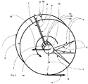
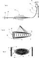
- a spacecraft with a landing system composed of a number of tethers is shown in the status in which due to high speed rotation of the landing system around the central platform the flexible structure of the landing system is fully deployed by rotation.
- Reference numeral 1 points to the core spacecraft, consisting of a rigid payload-encapsulating structure or platform, from which emanate flexible tethers of high tensile strength material, ideally Zylon ® for the axial tethers and/or gum-metal alloy (Ti-23Nb-0.7Ta-2Zr-1.2O) for the perimetric tethers, shaping a wheel like structure when in rotation.
- the plurality of the flexible tethers (axial and perimetric) need to be wrapped and secured around the core spacecraft (in order to fit in the limited volume under fairing ("New Glenn” at 6.35 meters)) and they are deployed right before touching the lunar surface, by placing the core spacecraft in high spin rate of about 8.62 revolutions per second (for a 30 meter radius). This number of revolutions generates enormous tension on the tethers which only Zylon ® so far can sustain (tensile strength 5.81150 MPa, density 5.61.56 g/cm3), or carbon fibers.
- “gum-metal” is used for the perimeter because it has better properties as regards recycling and reuse. Its wires and ropes can enable the second phase of landing system (MACEDONAS). Another argument for the choice of gum-metal alloy for the perimeter is the low friction coefficient. Gum metal is also suitable for momentum dumping through internal friction in multithreaded core configurations.
- the numeral 2 depicts the front plane of the flexible structure and the numeral 3 depicts the back plane. Additional planes, parallel to the front and to the back plane may be implemented as required.
- numeral 9 indicates a tether that is part of a middle tether plane.
- Numerals 6 and 7 indicate tethers belonging to the front and back plane respectively.
- Numerals 9 and 10 depict tethers connecting the front to the back plane, attached also to the middle plane.
- Numerals 21, 22, 23 indicate stiff structures, part of the core spacecraft upon which the tethers are secured.
- Numerals 4 indicate tethers that emanate perpendicular to the surface of the core spacecraft, while numeral 5 indicates tethers emanating from adjacent securing locations laterally located at the same supportive ring.
- Each junction point at the perimeter of the wheel shaped structure is tensioned by a plurality of tethers.
- Junction points a, b, c, d define a surface section of the perimeter which will act as the "sole" of the wheel-looking structure.
- the individual support tethers will consist of multithreaded Zylon ® ropes or similar material to provide the needed tensile support but be flexible enough to permit stowage for the launch.
- the vector of motion with numeral 11 indicates the velocity vector of the lowest point at the perimeter of the flexible structure
- the vector with numeral 12 indicates the velocity vector of the core of the spacecraft.
- the vector 15 indicates the direction of rotation.
- Vectors 11 and 12 shall be of equal size (1626 m/sec) at the beginning of the touch down, so that the perimeter of the flexible structure "follows" the displacement of the lunar surface, therefore eliminating the differential friction.
- the remaining friction (roll friction) is expected to be of minor value and dependent on the smoothness/roughness the lunar terrain.
- the cylindrical surface of the wheel can be shaped as corrugated surface with wave length tailored to the surface conditions.
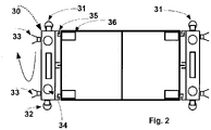
- Fig. 2 the core spacecraft is illustrated with two optional service modules.
- the service modules may be needed to reduce the length of the landing field that is necessary, considering that the rims of the craters hinder the exploitation of the complete swath of the flat areas and reduction of overshooting needs propulsion capability.
- the service modules are not required in all occasions and in particular on flat mare of large size. In the cases where service modules would not be required all the functional elements of the spacecraft shall be embedded in the core spacecraft, otherwise be the payload platform only.
- a semi rigid configuration of preferred embodiment is possible, where part of the tethers emanating from the rings could be replaced with rigid or compressible beams. These rigid or compressible beams could initially be folded along the side of the core spacecraft in single or multiple segments each.
- the basic wheel-looking spacecraft can advantageously establish the basis for more complex and efficient configurations of spacecraft.
- Bicycles, tricycles or 4 wheel vehicles of gargantuan dimensions could be established.
- Such spacecraft may become the ideal means of landing on lunar surface, once terrain evening capabilities become possible (beyond the natural flatness).
- the deceleration thrusters to achieve the touch down, as well as the payload compartments will not have to be in the volume of the core spacecraft as described in Fig. 2 but other more advantageous configurations could be established.
- the wheels will have to be adapted to higher load-bearing configurations. However the principle of spinning the wheels at such high speed to eliminate the differential friction shall be maintained.
- a wire woven and tethered system for capturing high velocity parcels (MACEDONAS)
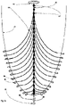
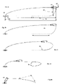
- Fig. 3a presents the architecture of a parcel capturing system that can be constructed principally by use of tether segments.
- the method described is code named "Momentum Absorption of Cargo Express Deliveries Orbiting Non-Atmospheric Somata (MACEDONAS).
- Numeral 41 depicts schematically a receptacle, consisting of a vertically hoisted apparatus made of a plurality of wire woven concave surfaces, arranged one inside the other, and all secured at the exterior rim (see 70 at Fig. 3d ), as successive barriers, of increasing resilience to impact of high velocity objects.
- the assumed incoming velocity of a parcel is in the range of 1626 m/sec.
- the receptacle is presented in more detail in Fig. 3d, Fig. 3e . and Fig. 5a and Fig.5b .
- Numeral 42 depicts a second (final) receptacle where the cargo eventually lands to rest. It shall have the configuration of either a "safety net", similar to the ones used in circuses or in its simplest configuration to consist of just a tether tensioned at some height from the ground by vertical trusses ( Fig. 6 numeral 97), and positioned precisely at a distance from the last engagement junction, equal to the length of the last branch plus an offset equal to the length of the tether that precedes the first branch of engagement ( Fig 6 . numeral 94). Therefore the length that numerals 94 and 96 of Fig. 6 indicate have to be equal.
- a safety net is the configuration of choice it can ideally be placed concentrically to a crater.
- Numeral 43 depicts the core tether, which connects to the initial receptacle to the dendritic arrangement of branch tethers.
- Numeral 44 depicts one "branch” tether that emanates from a connection point 43 and is secured to the ground at a “securing" point 46.
- Numeral 45 depicts the ideal (for a flat surface) theoretical limit of the arrangement of the branches, which have been positioned in a way (parabolic curve) not to cross each other once pulled by the central tether.
- Numeral 46 depicts a securing feature on the ground where excess wire is buried under low depth soil, or winded around a conical pile of lunar soil, (screened for stones). This soil, free from stones, can provide soft breaking of the tether once it reaches full tension.
- Numeral 47 depicts an other attach point, where the core tether is connected to a branch tether. Multiple such connection points along the length of the central tether mechanically engage and accelerate successive branches, as the receptacle with the payload may trip from the initial location towards the final receptacle.
- the individual tethers are dimensioned, laid and secured in such a way to steer the payload to land at the final landing spot 42 with greater positioning accuracy with respect to the initial entry at first receptacle 41. ie apart from momentum damping they act as bias loads to steer the parcel accordingly.
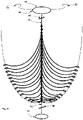
- Fig. 3b depicts a modified MACEDONAS in which the first receptacle (51) is not simply hoisted a few meters above ground but is suspended in high altitude by two lifting apparatuses (53).
- Numeral 52 depicts schematically the final receptacle, where the first receptacle with the payload shall come to rest.
- Numeral 54 depicts a connection point between the tether emanating from the lifting apparatus and the perimeter of the receptacle. That connection point is equipped with a quick disconnect (snap off) mechanism based on a brittle material.
- Numeral 55 indicates the core tether. Its length typically consists of the sum of the branched segment (from first branch join to the last branch join) plus the projection of the last branch to the core tether plus the pre-branch lead and it shall be equal to the segment indicated by numeral 57.
- Numeral 56 indicates that the length may vary.
- numeral 58 indicates that the location of the final receptacle shall be at a distance from the last engagement point equal to the sum of the branched segment plus the pre-branch lead (plus the projection of the last branch to the core tether).
- the system therefore is adaptable to catching payloads from different altitudes with dynamic positioning of the first receptacle.
- volatiles of almost any kind can be used to propel apparatuses that would lift the receptacle at significant altitudes, therefore requiring less fuel to reach the rendezvous (with the receptacle) point.
- Fig. 3c depicts from lateral perspective the MACEDONAS system presented in Fig. 3b .
- Numeral 61 depicts schematically the receptacle (for more detail see Fig. 3d and Fig. 3e as well as Fig. 5a ).
- Numeral 62 depicts the lifting apparatuses. Preferably operating on pressurized volatiles harvested locally (ISRU).
- ISRU pressurized volatiles harvested locally
- Numeral 63 depicts the core tether.
- Numeral 64 indicates the height of which the receptacle has been lifted
- Numeral 65 depicts the dendritic part of the MACEDONAS.
- Numeral 66 indicates the distance of the final receptacle from the end of the dendritic system. (Note: the end of the dendritic system is at the point where the last branch can reach, ie it is at a distance from the last connection point equal to the projection of the last branch on the core tether).
- Numeral 67 indicates the final receptacle.
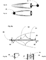
- Fig. 3d depicts the first receptacle from side view and Fig. 3e depicts the same at a front view.
- Numeral 70 indicates the rim of the first concave surface of the receptacle, on which rim actually are connected also the rims of the embedded concave surfaces. In this way the momentum from the parcel is transferred to the rim and through the anchor point (79) to the core tether.
- Numeral 71 depicts the connection points for the lifting / hoisting of the receptacle. It is advantageously equipped with a quick disconnect (snap off) mounting (glass hook possibly or other brittle material).
- Numeral 72 indicates the length of the receptacle whole
- Numeral 73 indicates a tether segment used for suspension of the receptacle.
- Numeral 74 indicates a truss for securing a tether that suspends the receptacle.
- Numeral 75 indicates the width of the rim
- Numeral 76 indicates the height of the rim.
- Numerals 77 indicate the volumes between successive concave surfaces. It can be any of the four a) void, b) filled with compacted mixture of clay and slit, c) filled by a pre-shaped closed-cell ceramic foam, or d) antiballistic fabric, or a combination of the a,b,c,d depending on how much shock a parcel can sustain.
- Numeral 79 indicates the anchor point where the core tether is secured.
- Fig. 5a depicts the receptacle as it is before receiving a parcel and
- Fig. 5b depicts the same as after receiving a parcel, in which case all but one of the concave surfaces have been perforated and only the external restrains the parcel from escaping.
- the momentum loss of the parcel & its transfer to the anchor point (79), needed to accelerate the receptacle, is advantageously divided in 8 steps, therefore the sock impact on the parcel is also advantageously reduced significantly (other number of barriers can be deviced according to specific needs).
- Numeral 50 indicates a unit of parcel. It is schematically being presented as spherical. This implies that it will constitute a passive unit of parcel to be delivered to the receptacle entrance at the right velocity and angle form an over-orbiting delivery spacecraft (OODS). That is simple to achieve even with a mechanical ejector that will eject such unit parcel at the direction opposite to the motion of the OODS, so that the unit payload loses part of its kinetic energy and altitude. The timing though of such injection is of high importance and corresponding calculations will have to be performed for each parcel drop as the orbit of the OODS will also be affected by each parcel ejection.
- OODS over-orbiting delivery spacecraft
- Figures 4a to 4e depict successive instances in time of the parcel momentum absorption.
- Fig. 4a is depicted the instance just prior to the entry of the parcel (82 (indicated with numeral 50 in Fig 5 )) at the rim of the receptacle (80).
- Fig. 4b depicts the parcel having perforated the first 7 concave surfaces and be captured by the final (and most robust) external concave surface.
- Fig. 4c depicts the receptacle detached & dispatched from its “anchoring" location and be propelled along a trajectory (83) indicated by the dotted "constrained ballistic trajectory". Note: it is not pure ballistic trajectory but constrained ballistic trajectory, constrained by the mechanics of the core tether and the dendritic tether system. At this moment 6 nodes of wire branches have been engaged (lifted) and add drag to the progression of the parcel carrying receptacle.
- Fig. 4d depicts the receptacle at the moment it has progressed that much that all 13 nodes of wire branches have been engaged (lifted) (but not fully stretched the corresponding wire/rope branches).
- Fig. 4e depicts the receptacle at the moment it has progressed that much that has engaged all joints to the wire/rope branches and has stretched them to their maximum length.
- the receptacle must have zero remaining momentum and shall land safely on the final receptacle (87 in Fig. 4e , or 81 in Fig. 4a )
- the system is rather versatile as regards accepting parcels of different masses.
- dendritic systems of 13 nodes we use dendritic systems of 13 nodes but this can be altered at will.
- the length of the dendritic system, the length of the branches and their initial layout, as well as the thickness of the wire/rope tethers are all configurable parameters. Further, repeatability, with the exception of the first receptacle that will need to be replaced after each mission (and recycled), all other elements can be put back in place for the next mission in a matter of minutes, by pulling the anchor point/the core tether start back to the initial "anchor" location.
- the branches of the dendritic system will be laid naturally to their initial configuration (provided the soil does not hinder their motion).
- Fig. 6a depicts from top view, a specific embodiment of final receptacle made of two trusses and horizontal wires, at the instance where the first receptacle has reached its destination.
- Fig. 6b is a side view of the receptacle hanging at the end receptacle at some distance from the ground.
- Fig. 6c front view depicting the horizontal to the ground wires/ropes, connecting the trusses, for limiting the first receptacle to loop around the top wire.
Landscapes
- Engineering & Computer Science (AREA)
- Remote Sensing (AREA)
- Aviation & Aerospace Engineering (AREA)
- Physics & Mathematics (AREA)
- Astronomy & Astrophysics (AREA)
- General Physics & Mathematics (AREA)
- Life Sciences & Earth Sciences (AREA)
- Sustainable Development (AREA)
- Tires In General (AREA)
Priority Applications (4)
| Application Number | Priority Date | Filing Date | Title |
|---|---|---|---|
| EP21165077.5A EP4063281B1 (fr) | 2021-03-25 | 2021-03-25 | Système d'atterrissage à deux phases pour la lune et ses éléments de mise en oeuvre |
| PCT/EP2022/057971 WO2022200596A1 (fr) | 2021-03-25 | 2022-03-25 | Système d'atterrissage à deux phases pour la lune et ses éléments de mise en oeuvre |
| US18/283,980 US12286246B2 (en) | 2021-03-25 | 2022-03-25 | Two phase landing system for the moon and its implementation elements |
| US19/190,621 US20250263179A1 (en) | 2021-03-25 | 2025-04-26 | Two phase landing system for the moon and its implementation elements |
Applications Claiming Priority (1)
| Application Number | Priority Date | Filing Date | Title |
|---|---|---|---|
| EP21165077.5A EP4063281B1 (fr) | 2021-03-25 | 2021-03-25 | Système d'atterrissage à deux phases pour la lune et ses éléments de mise en oeuvre |
Publications (3)
| Publication Number | Publication Date |
|---|---|
| EP4063281A1 true EP4063281A1 (fr) | 2022-09-28 |
| EP4063281C0 EP4063281C0 (fr) | 2023-11-29 |
| EP4063281B1 EP4063281B1 (fr) | 2023-11-29 |
Family
ID=75252330
Family Applications (1)
| Application Number | Title | Priority Date | Filing Date |
|---|---|---|---|
| EP21165077.5A Active EP4063281B1 (fr) | 2021-03-25 | 2021-03-25 | Système d'atterrissage à deux phases pour la lune et ses éléments de mise en oeuvre |
Country Status (3)
| Country | Link |
|---|---|
| US (2) | US12286246B2 (fr) |
| EP (1) | EP4063281B1 (fr) |
| WO (1) | WO2022200596A1 (fr) |
Citations (6)
| Publication number | Priority date | Publication date | Assignee | Title |
|---|---|---|---|---|
| US6565044B1 (en) * | 2002-03-14 | 2003-05-20 | The United States Of America As Represented By The Administrator Of The National Aeronautics And Space Administration | Combination solar sail and electrodynamic tether propulsion system |
| US20080099624A1 (en) * | 2006-10-16 | 2008-05-01 | Erik Evjenth | Space tether transport system |
| CN105783610A (zh) * | 2016-03-14 | 2016-07-20 | 门德君 | 海上火箭回收装置 |
| CN106347716B (zh) * | 2016-09-29 | 2018-08-21 | 西北工业大学 | 一种用于空间对接的陀螺式能量转换装置及方法 |
| WO2019135786A1 (fr) * | 2017-06-22 | 2019-07-11 | Lenard Roger X | Collecte, transport et archivage d'échantillons et de ressources dans des conditions correspondant à zéro g ou à une fraction de g |
| CN110185732A (zh) * | 2019-06-03 | 2019-08-30 | 哈尔滨工业大学 | 航天器回收直线电磁阻尼装置 |
Family Cites Families (18)
| Publication number | Priority date | Publication date | Assignee | Title |
|---|---|---|---|---|
| US2854201A (en) * | 1954-06-11 | 1958-09-30 | All American Eng Co | Aircraft barrier |
| US2957657A (en) * | 1955-01-04 | 1960-10-25 | Fricder | Aircraft net barrier |
| GB1448197A (en) * | 1972-11-16 | 1976-09-02 | Secr Defence | Arrester gear |
| US3810595A (en) * | 1972-12-05 | 1974-05-14 | All American Ind | Aircraft arresting barrier |
| US3897920A (en) * | 1974-05-20 | 1975-08-05 | Us Navy | Aircraft barricade jet-net |
| FR2360467A1 (fr) * | 1976-08-05 | 1978-03-03 | Aerazur Constr Aeronaut | Filet pour l'arret des avions |
| US4566658A (en) * | 1983-08-01 | 1986-01-28 | The United States Of America As Represented By The Secretary Of The Navy | Aircraft barricade |
| US4809933A (en) * | 1984-02-21 | 1989-03-07 | Wickes Manufacturing Company | Portable aircraft arresting apparatus |
| US4979701A (en) * | 1989-03-01 | 1990-12-25 | Patron Inc. | Aircraft arresting elemental net with multiple independent bottom horizontal straps |
| IL162224A (en) * | 2004-05-30 | 2011-03-31 | Rafael Advanced Defense Sys | Unmanned aerial vehicle (uav) deceleration system |
| US8054198B2 (en) * | 2008-11-26 | 2011-11-08 | The Boeing Company | Spherical sensor and data collection vehicles |
| US8453967B2 (en) * | 2010-06-09 | 2013-06-04 | Aai Corporation | Mobile aircraft recovery system |
| WO2015191804A2 (fr) * | 2014-06-11 | 2015-12-17 | Engineered Arresting Systems Corporation | Système de récupération de véhicule aérien sans pilote |
| US11192646B2 (en) * | 2018-10-03 | 2021-12-07 | Sarcos Corp. | Anchored aerial countermeasures for rapid deployment and neutralizing of target aerial vehicles |
| CN109305378B (zh) * | 2018-11-26 | 2020-06-09 | 南京林业大学 | 一种无人机回收装置 |
| US11834180B2 (en) * | 2019-01-19 | 2023-12-05 | Christopher Kyle Turner | Precision automated air-to-ground delivery system and related methods |
| UY39409A (es) * | 2020-09-04 | 2022-03-31 | Parachute Logistics Llc | Sistema logístico de bajo costo capital y operacional y método de entrega rápida y masiva de mercancia de comercio electrónico en grandes áreas geográficas |
| CN112340045A (zh) * | 2020-11-20 | 2021-02-09 | 江西洪都航空工业集团有限责任公司 | 一种小型飞行器撞网回收装置 |
-
2021
- 2021-03-25 EP EP21165077.5A patent/EP4063281B1/fr active Active
-
2022
- 2022-03-25 WO PCT/EP2022/057971 patent/WO2022200596A1/fr not_active Ceased
- 2022-03-25 US US18/283,980 patent/US12286246B2/en active Active
-
2025
- 2025-04-26 US US19/190,621 patent/US20250263179A1/en active Pending
Patent Citations (6)
| Publication number | Priority date | Publication date | Assignee | Title |
|---|---|---|---|---|
| US6565044B1 (en) * | 2002-03-14 | 2003-05-20 | The United States Of America As Represented By The Administrator Of The National Aeronautics And Space Administration | Combination solar sail and electrodynamic tether propulsion system |
| US20080099624A1 (en) * | 2006-10-16 | 2008-05-01 | Erik Evjenth | Space tether transport system |
| CN105783610A (zh) * | 2016-03-14 | 2016-07-20 | 门德君 | 海上火箭回收装置 |
| CN106347716B (zh) * | 2016-09-29 | 2018-08-21 | 西北工业大学 | 一种用于空间对接的陀螺式能量转换装置及方法 |
| WO2019135786A1 (fr) * | 2017-06-22 | 2019-07-11 | Lenard Roger X | Collecte, transport et archivage d'échantillons et de ressources dans des conditions correspondant à zéro g ou à une fraction de g |
| CN110185732A (zh) * | 2019-06-03 | 2019-08-30 | 哈尔滨工业大学 | 航天器回收直线电磁阻尼装置 |
Also Published As
| Publication number | Publication date |
|---|---|
| US12286246B2 (en) | 2025-04-29 |
| EP4063281C0 (fr) | 2023-11-29 |
| US20240166378A1 (en) | 2024-05-23 |
| US20250263179A1 (en) | 2025-08-21 |
| WO2022200596A1 (fr) | 2022-09-29 |
| EP4063281B1 (fr) | 2023-11-29 |
Similar Documents
| Publication | Publication Date | Title |
|---|---|---|
| CA2677942C (fr) | Ascenseur spatial | |
| JP5817739B2 (ja) | ロケット発射システムおよび支持装置 | |
| US7131613B2 (en) | High-altitude launching of rockets lifted by helium devices and platforms with rotatable wings | |
| RU2344973C1 (ru) | Земле-лунный комплекс (злк) | |
| RU2735441C1 (ru) | Космический лифт для доставки пассажиров и грузов с поверхности Земли или иной планеты на низкую орбиту и обратно и способ его строительства | |
| US11014692B2 (en) | Elevated load-bearing platform | |
| CN113195362B (zh) | 全球运输系统和用于将有效载荷置于圆形轨道中的方法 | |
| EP4063281B1 (fr) | Système d'atterrissage à deux phases pour la lune et ses éléments de mise en oeuvre | |
| WO2022170888A1 (fr) | Système de lancement et procédé de lancement d'engin spatial, et engin spatial | |
| US20080099624A1 (en) | Space tether transport system | |
| CN111977029B (zh) | 一种多用途传输系统及其建造方法 | |
| Prado | From the Earth to the Moon by Gondola | |
| BIRCH | ORBITAL RING SYSTEMS AND JACOB'5 LADDERS*'ll | |
| Hypes et al. | Concepts for manned lunar habitats | |
| CN118723126A (zh) | 改变空间物体与星体距离及速度的方法和系统 | |
| Arnold et al. | Advanced propulsion for LEO-Moon transport. 2: Tether configurations in the LEO-Moon system | |
| Barcelo et al. | Space tethers: Applications and implementations | |
| Arnold et al. | IN THE LEO-MOON SYSTEM | |
| BIRCH | A method of transferring payloads into space without using rockets has been presented in Part I, in which massive rings encircle the globe in a low orbit supporting stationary" sky-hooks," from which cables hang down to any point on the Earth's surface. Vehicles can climb up these “ladders' into orbit, or can accelerate along the rings. The structure and | |
| Sheets et al. | Space Elevator: A Scientific Application | |
| Arnold | ADVANCED PROPULSION FOR LEO-MOON TRANSPORT: II. TEIBER CONFIGURATIONS IN TllE LEO-MOON SYSTEM | |
| CN111038736A (zh) | 一种航天器慢速高抛式发射方法及发射平台 | |
| Pearson et al. | Integrated Lunar Transportation System | |
| Bolonkin | Space Towers | |
| Sparks | Analysis of Space Elevator Technology |
Legal Events
| Date | Code | Title | Description |
|---|---|---|---|
| PUAI | Public reference made under article 153(3) epc to a published international application that has entered the european phase |
Free format text: ORIGINAL CODE: 0009012 |
|
| STAA | Information on the status of an ep patent application or granted ep patent |
Free format text: STATUS: THE APPLICATION HAS BEEN PUBLISHED |
|
| AK | Designated contracting states |
Kind code of ref document: A1 Designated state(s): AL AT BE BG CH CY CZ DE DK EE ES FI FR GB GR HR HU IE IS IT LI LT LU LV MC MK MT NL NO PL PT RO RS SE SI SK SM TR |
|
| STAA | Information on the status of an ep patent application or granted ep patent |
Free format text: STATUS: REQUEST FOR EXAMINATION WAS MADE |
|
| 17P | Request for examination filed |
Effective date: 20230328 |
|
| RBV | Designated contracting states (corrected) |
Designated state(s): AL AT BE BG CH CY CZ DE DK EE ES FI FR GB GR HR HU IE IS IT LI LT LU LV MC MK MT NL NO PL PT RO RS SE SI SK SM TR |
|
| GRAP | Despatch of communication of intention to grant a patent |
Free format text: ORIGINAL CODE: EPIDOSNIGR1 |
|
| STAA | Information on the status of an ep patent application or granted ep patent |
Free format text: STATUS: GRANT OF PATENT IS INTENDED |
|
| RIC1 | Information provided on ipc code assigned before grant |
Ipc: B64G 1/10 20060101ALN20230522BHEP Ipc: B64G 99/00 20090101ALI20230522BHEP Ipc: B64G 1/64 20060101ALI20230522BHEP Ipc: B64G 1/62 20060101AFI20230522BHEP |
|
| RIC1 | Information provided on ipc code assigned before grant |
Ipc: B64G 1/10 20060101ALN20230530BHEP Ipc: B64G 99/00 20090101ALI20230530BHEP Ipc: B64G 1/64 20060101ALI20230530BHEP Ipc: B64G 1/62 20060101AFI20230530BHEP |
|
| INTG | Intention to grant announced |
Effective date: 20230621 |
|
| GRAS | Grant fee paid |
Free format text: ORIGINAL CODE: EPIDOSNIGR3 |
|
| GRAA | (expected) grant |
Free format text: ORIGINAL CODE: 0009210 |
|
| STAA | Information on the status of an ep patent application or granted ep patent |
Free format text: STATUS: THE PATENT HAS BEEN GRANTED |
|
| AK | Designated contracting states |
Kind code of ref document: B1 Designated state(s): AL AT BE BG CH CY CZ DE DK EE ES FI FR GB GR HR HU IE IS IT LI LT LU LV MC MK MT NL NO PL PT RO RS SE SI SK SM TR |
|
| REG | Reference to a national code |
Ref country code: GB Ref legal event code: FG4D |
|
| REG | Reference to a national code |
Ref country code: CH Ref legal event code: EP |
|
| REG | Reference to a national code |
Ref country code: DE Ref legal event code: R096 Ref document number: 602021007161 Country of ref document: DE |
|
| REG | Reference to a national code |
Ref country code: IE Ref legal event code: FG4D |
|
| U01 | Request for unitary effect filed |
Effective date: 20231229 |
|
| U07 | Unitary effect registered |
Designated state(s): AT BE BG DE DK EE FI FR IT LT LU LV MT NL PT SE SI Effective date: 20240111 |
|
| PG25 | Lapsed in a contracting state [announced via postgrant information from national office to epo] |
Ref country code: GR Free format text: LAPSE BECAUSE OF FAILURE TO SUBMIT A TRANSLATION OF THE DESCRIPTION OR TO PAY THE FEE WITHIN THE PRESCRIBED TIME-LIMIT Effective date: 20240301 |
|
| PG25 | Lapsed in a contracting state [announced via postgrant information from national office to epo] |
Ref country code: IS Free format text: LAPSE BECAUSE OF FAILURE TO SUBMIT A TRANSLATION OF THE DESCRIPTION OR TO PAY THE FEE WITHIN THE PRESCRIBED TIME-LIMIT Effective date: 20240329 |
|
| PG25 | Lapsed in a contracting state [announced via postgrant information from national office to epo] |
Ref country code: ES Free format text: LAPSE BECAUSE OF FAILURE TO SUBMIT A TRANSLATION OF THE DESCRIPTION OR TO PAY THE FEE WITHIN THE PRESCRIBED TIME-LIMIT Effective date: 20231129 |
|
| PG25 | Lapsed in a contracting state [announced via postgrant information from national office to epo] |
Ref country code: IS Free format text: LAPSE BECAUSE OF FAILURE TO SUBMIT A TRANSLATION OF THE DESCRIPTION OR TO PAY THE FEE WITHIN THE PRESCRIBED TIME-LIMIT Effective date: 20240329 Ref country code: GR Free format text: LAPSE BECAUSE OF FAILURE TO SUBMIT A TRANSLATION OF THE DESCRIPTION OR TO PAY THE FEE WITHIN THE PRESCRIBED TIME-LIMIT Effective date: 20240301 Ref country code: ES Free format text: LAPSE BECAUSE OF FAILURE TO SUBMIT A TRANSLATION OF THE DESCRIPTION OR TO PAY THE FEE WITHIN THE PRESCRIBED TIME-LIMIT Effective date: 20231129 |
|
| U20 | Renewal fee for the european patent with unitary effect paid |
Year of fee payment: 4 Effective date: 20240331 |
|
| PG25 | Lapsed in a contracting state [announced via postgrant information from national office to epo] |
Ref country code: RS Free format text: LAPSE BECAUSE OF FAILURE TO SUBMIT A TRANSLATION OF THE DESCRIPTION OR TO PAY THE FEE WITHIN THE PRESCRIBED TIME-LIMIT Effective date: 20231129 Ref country code: PL Free format text: LAPSE BECAUSE OF FAILURE TO SUBMIT A TRANSLATION OF THE DESCRIPTION OR TO PAY THE FEE WITHIN THE PRESCRIBED TIME-LIMIT Effective date: 20231129 Ref country code: NO Free format text: LAPSE BECAUSE OF FAILURE TO SUBMIT A TRANSLATION OF THE DESCRIPTION OR TO PAY THE FEE WITHIN THE PRESCRIBED TIME-LIMIT Effective date: 20240229 Ref country code: HR Free format text: LAPSE BECAUSE OF FAILURE TO SUBMIT A TRANSLATION OF THE DESCRIPTION OR TO PAY THE FEE WITHIN THE PRESCRIBED TIME-LIMIT Effective date: 20231129 |
|
| PG25 | Lapsed in a contracting state [announced via postgrant information from national office to epo] |
Ref country code: CZ Free format text: LAPSE BECAUSE OF FAILURE TO SUBMIT A TRANSLATION OF THE DESCRIPTION OR TO PAY THE FEE WITHIN THE PRESCRIBED TIME-LIMIT Effective date: 20231129 |
|
| PG25 | Lapsed in a contracting state [announced via postgrant information from national office to epo] |
Ref country code: SK Free format text: LAPSE BECAUSE OF FAILURE TO SUBMIT A TRANSLATION OF THE DESCRIPTION OR TO PAY THE FEE WITHIN THE PRESCRIBED TIME-LIMIT Effective date: 20231129 |
|
| PG25 | Lapsed in a contracting state [announced via postgrant information from national office to epo] |
Ref country code: SM Free format text: LAPSE BECAUSE OF FAILURE TO SUBMIT A TRANSLATION OF THE DESCRIPTION OR TO PAY THE FEE WITHIN THE PRESCRIBED TIME-LIMIT Effective date: 20231129 Ref country code: SK Free format text: LAPSE BECAUSE OF FAILURE TO SUBMIT A TRANSLATION OF THE DESCRIPTION OR TO PAY THE FEE WITHIN THE PRESCRIBED TIME-LIMIT Effective date: 20231129 Ref country code: RO Free format text: LAPSE BECAUSE OF FAILURE TO SUBMIT A TRANSLATION OF THE DESCRIPTION OR TO PAY THE FEE WITHIN THE PRESCRIBED TIME-LIMIT Effective date: 20231129 Ref country code: CZ Free format text: LAPSE BECAUSE OF FAILURE TO SUBMIT A TRANSLATION OF THE DESCRIPTION OR TO PAY THE FEE WITHIN THE PRESCRIBED TIME-LIMIT Effective date: 20231129 |
|
| REG | Reference to a national code |
Ref country code: DE Ref legal event code: R097 Ref document number: 602021007161 Country of ref document: DE |
|
| PLBE | No opposition filed within time limit |
Free format text: ORIGINAL CODE: 0009261 |
|
| STAA | Information on the status of an ep patent application or granted ep patent |
Free format text: STATUS: NO OPPOSITION FILED WITHIN TIME LIMIT |
|
| REG | Reference to a national code |
Ref country code: CH Ref legal event code: PL |
|
| 26N | No opposition filed |
Effective date: 20240830 |
|
| PG25 | Lapsed in a contracting state [announced via postgrant information from national office to epo] |
Ref country code: MC Free format text: LAPSE BECAUSE OF FAILURE TO SUBMIT A TRANSLATION OF THE DESCRIPTION OR TO PAY THE FEE WITHIN THE PRESCRIBED TIME-LIMIT Effective date: 20231129 |
|
| PG25 | Lapsed in a contracting state [announced via postgrant information from national office to epo] |
Ref country code: MC Free format text: LAPSE BECAUSE OF FAILURE TO SUBMIT A TRANSLATION OF THE DESCRIPTION OR TO PAY THE FEE WITHIN THE PRESCRIBED TIME-LIMIT Effective date: 20231129 |
|
| PG25 | Lapsed in a contracting state [announced via postgrant information from national office to epo] |
Ref country code: IE Free format text: LAPSE BECAUSE OF NON-PAYMENT OF DUE FEES Effective date: 20240325 |
|
| PG25 | Lapsed in a contracting state [announced via postgrant information from national office to epo] |
Ref country code: IE Free format text: LAPSE BECAUSE OF NON-PAYMENT OF DUE FEES Effective date: 20240325 Ref country code: CH Free format text: LAPSE BECAUSE OF NON-PAYMENT OF DUE FEES Effective date: 20240331 |
|
| U20 | Renewal fee for the european patent with unitary effect paid |
Year of fee payment: 5 Effective date: 20250331 |
|
| PG25 | Lapsed in a contracting state [announced via postgrant information from national office to epo] |
Ref country code: CY Free format text: LAPSE BECAUSE OF FAILURE TO SUBMIT A TRANSLATION OF THE DESCRIPTION OR TO PAY THE FEE WITHIN THE PRESCRIBED TIME-LIMIT; INVALID AB INITIO Effective date: 20210325 |
|
| PG25 | Lapsed in a contracting state [announced via postgrant information from national office to epo] |
Ref country code: HU Free format text: LAPSE BECAUSE OF FAILURE TO SUBMIT A TRANSLATION OF THE DESCRIPTION OR TO PAY THE FEE WITHIN THE PRESCRIBED TIME-LIMIT; INVALID AB INITIO Effective date: 20210325 |
|
| GBPC | Gb: european patent ceased through non-payment of renewal fee |
Effective date: 20250325 |
|
| PG25 | Lapsed in a contracting state [announced via postgrant information from national office to epo] |
Ref country code: TR Free format text: LAPSE BECAUSE OF FAILURE TO SUBMIT A TRANSLATION OF THE DESCRIPTION OR TO PAY THE FEE WITHIN THE PRESCRIBED TIME-LIMIT Effective date: 20231129 |
|
| PG25 | Lapsed in a contracting state [announced via postgrant information from national office to epo] |
Ref country code: GB Free format text: LAPSE BECAUSE OF NON-PAYMENT OF DUE FEES Effective date: 20250325 |