EP4063311A1 - Kranabstützplatte - Google Patents
Kranabstützplatte Download PDFInfo
- Publication number
- EP4063311A1 EP4063311A1 EP22161413.4A EP22161413A EP4063311A1 EP 4063311 A1 EP4063311 A1 EP 4063311A1 EP 22161413 A EP22161413 A EP 22161413A EP 4063311 A1 EP4063311 A1 EP 4063311A1
- Authority
- EP
- European Patent Office
- Prior art keywords
- crane
- support plate
- support
- foot
- fastening device
- Prior art date
- Legal status (The legal status is an assumption and is not a legal conclusion. Google has not performed a legal analysis and makes no representation as to the accuracy of the status listed.)
- Granted
Links
Images


Classifications
-
- B—PERFORMING OPERATIONS; TRANSPORTING
- B66—HOISTING; LIFTING; HAULING
- B66C—CRANES; LOAD-ENGAGING ELEMENTS OR DEVICES FOR CRANES, CAPSTANS, WINCHES, OR TACKLES
- B66C23/00—Cranes comprising essentially a beam, boom, or triangular structure acting as a cantilever and mounted for translatory of swinging movements in vertical or horizontal planes or a combination of such movements, e.g. jib-cranes, derricks, tower cranes
- B66C23/62—Constructional features or details
- B66C23/72—Counterweights or supports for balancing lifting couples
- B66C23/78—Supports, e.g. outriggers, for mobile cranes
-
- B—PERFORMING OPERATIONS; TRANSPORTING
- B66—HOISTING; LIFTING; HAULING
- B66C—CRANES; LOAD-ENGAGING ELEMENTS OR DEVICES FOR CRANES, CAPSTANS, WINCHES, OR TACKLES
- B66C23/00—Cranes comprising essentially a beam, boom, or triangular structure acting as a cantilever and mounted for translatory of swinging movements in vertical or horizontal planes or a combination of such movements, e.g. jib-cranes, derricks, tower cranes
- B66C23/62—Constructional features or details
- B66C23/72—Counterweights or supports for balancing lifting couples
- B66C23/78—Supports, e.g. outriggers, for mobile cranes
- B66C23/80—Supports, e.g. outriggers, for mobile cranes hydraulically actuated
Definitions
- the invention relates to a crane support plate for a support foot on a support arm of a mobile crane vehicle.
- a mobile crane vehicle is a mobile jib crane on a wheel or crawler chassis.
- a support is required to work safely with a mobile crane vehicle.
- the mobile crane vehicle is supported by hydraulic support cylinders, which are arranged on swing-out and/or extendable support arms. Support feet that can be placed on the ground are provided on the support cylinders. Usually four support arms are provided with just as many support feet.
- the outrigger ensures that a high load-bearing capacity is achieved as the outrigger arms reduce the tilting moment of the mobile crane vehicle, which is determined by the product of the load and the length of the outrigger arm. In addition, the effective floor area is increased.
- Crane support pads can be used to better distribute the compressive forces of the support feet.
- the crane support plate is positioned between the ground and the support leg and distributes the compressive force of the support leg over a larger floor area in order to ensure that the floor on which the mobile crane vehicle is built can withstand the pressure even under high loads and the floor sinks or even sinks Tilting of the mobile wreath vehicle is avoided.
- Small crane outrigger pads are usually made of plastic and have longitudinal and transverse dimensions that rarely exceed about twice the underside of the outrigger. When maneuvering and relocating the mobile crane vehicle in the construction site area, they can be used more easily Way to be carried by one person to their new working position under the support feet.
- a crane support plate for the heavy-duty area or for a soft ground has a base area that is many times, in particular more than ten times larger than the underside of the support foot.
- the crane support plate is usually made of steel.
- Such a crane support plate can weigh several hundred kilograms and can only be moved with effort and mechanical assistance.
- the term "crane mats" is also used for such crane support plates. There are different sizes and shapes.
- the crane support plates must also be moved.
- the associated laying of a heavy crane support plate is associated with considerable effort.
- a mobile crane vehicle with four support feet requires four crane support plates, each of which weighs several hundred kilograms and can therefore only be moved with considerable effort.
- the object is to specify a device that reduces the effort involved in repositioning the crane support plates.
- the object is achieved by a crane support plate having the features of claim 1.
- the crane support plate is essentially made of metal.
- It comprises a fastening device for a support foot on a support arm of a mobile crane vehicle, which can be detachably connected to the support foot, so that when the mobile crane vehicle is maneuvered, the crane support plate raised by the support foot hangs on the support arm of the mobile crane vehicle that cannot be fully retracted and/or pivoted in completely.
- the essentially metal or metal crane support plate advantageously has metal, in particular steel, outer walls and a metal, in particular steel, inner structure. Crane outrigger pads made of a composite material made of plastic with only metallic fibers are not covered. Nevertheless, a minor part of the components of the essentially metal crane support plate can be made of other materials, for example plastic.
- the crane support plate is essentially made of steel and has a rectangular base.
- Ring support plates of this type do not have to be solid, but can be formed with a honeycomb structure on the inside, for example.
- the collar support plates can be designed for compressive loads of one or more decatons and more.
- the crane support plate is advantageously intended for use in a mobile crane vehicle with a maximum crane load capacity of at least 25 t.
- the fastening device is advantageously made essentially or entirely of metal, in particular steel.
- a recess is provided in an upper side of the rim support plate, in which the support leg can be placed on the bottom of the recess.
- the shape and size of the recess and the bottom of the foot correspond. In this way, the support foot can be optimally placed.
- the fastening device on the crane support plate is designed for a detachable positive connection with the support foot. Except for possible play, the form-fitting connection prevents movement between the components, so that the crane support plate cannot shift or even come loose during repositioning, which increases work safety and prevents accidents. That Vertical play can be significantly larger than play parallel to the top of the crane support plate, so that the form fit is concentrated on the horizontal and primarily movements parallel to the top of the crane support plate are prevented.
- the fastening device comprises a screw connection, which forms a secure and strong, but simple and easily detachable connection.
- the fastening device on the crane support plate has webs that are movable or separate from the crane support plate, that is, webs that can be removed from the crane support plate.
- the webs can be attached to the crane base plate so that they extend over the support foot on the crane base plate and connect it to the crane base plate. The webs hold the support foot on the crane support plate, so that a firm and advantageously form-fitting connection is formed between the components.
- the fastening device has an insertion device.
- the support foot can be inserted into the insertion device in such a way that no movement is possible apart from movement in the opposite direction and play.
- a lock can also be provided for the fastening devices mentioned above.
- the fastening device comprises an exchangeable adapter device which can be connected to the support foot, so that the adapter device is coupled between the support foot and the crane support plate.
- the crane support plate can be equipped with different Support foot types can be connected by attaching an adapter device corresponding to the support foot type to the crane support plate.
- figure 1 1 schematically shows a front view of an exemplary embodiment of a mobile crane vehicle, which is supported on the ground 3 via crane support plates 1 .
- Support is provided by hydraulic support cylinders 5, which are each arranged on support arms 7 that can be swung out and extended.
- Two support arms 7 are arranged on each side of the mobile crane vehicle, which are swung out and extended for support.
- a support foot 9 is arranged on the underside of the support cylinder 5 and rests on the crane support plate 1 .
- the pivoted and extended support arms 7 increase the effective base area of the mobile crane vehicle, thereby resulting in a high load-bearing capacity.
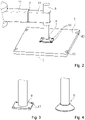
- FIG 2 shows a three-dimensional representation of an embodiment of a support arm 7 with a hydraulic support cylinder 5 and a support leg 9 on an embodiment of a crane support plate 1.
- the pivoted and extended support arm 7 extends to the side of the mobile crane vehicle.
- the support arm 7 is constructed as a telescopic arm in segments, with the movement of the extension segments 11 taking place hydraulically.
- the hydraulic support cylinder 5 is arranged on the side of the support arm 7 facing away from the mobile crane vehicle and is designed to lower and raise the support foot 9 facing the floor 3 .
- the support takes place with the support foot 9 lowered.
- the support foot 9 comprises a truncated pyramid-shaped area and a plate-shaped area with a square base between which is a shoulder.
- a foot bottom is placed on the crane support plate 1, which distributes the pressure of the support foot 9 over an area larger than the foot bottom.
- the crane support plate 1 is firmly connected to the support foot 9 so that, apart from possible play, no relative movement between the components connected to one another is possible.
- the connection is made by a screw connection.
- the fastening device of the crane support plate 1 comprises screws 15 and threaded holes in the crane support plate 1. The screws 15 engage through holes in the support foot 9 in the corresponding size and position threaded holes of the crane support plate 1, thus forming a firm but detachable connection.
- the operation of the crane support plate 1 is based on the physical effect of increasing the "force per area". By increasing the area on which the compressive force acts, the force acting on a surface element decreases. The following example illustrates this. A load of 50 t acting on an area of 0.25 m 2 results in a distributed load of 200 t / m 2 . However, if 50 t acts on an area of 6 m 2 , the surface load is significantly lower at 8.33 t/m 2 .
- a large crane support plate 1 for heavy loads and/or soft ground 3 is usually made of steel and not solid.
- the basic rectangular shape has an outer shell made of steel. Inside, for example, is a honeycomb structure that distributes the load. Nevertheless, the weight of the crane support plate 1 is several hundred kilograms, so that it has to be placed at its place of use by machine.
- Edge area eyelets 13 provided that allow transport with a crane.
- alternative exemplary embodiments of means for lifting the crane support plate, so-called attachment points can be provided, for example welded-on eyelets, round steel, buffer blocks.
- stacking corners are provided so that crane support plates can be aligned in a simple manner when stacked on top of one another for storage or transport.
- the fastening device of the crane support plate 1 and the firm connection it provides to the support foot 9 enables the crane operator to raise the crane support plate 1 by means of the hydraulic support cylinder 5 by lifting the support foot 9 . This can be done by an electrical control device in the mobile crane vehicle. Due to the size of the crane support plate 1, it is not possible to fully retract or swing back the support arm 7 so that the raised crane support plate 1 hangs on the at least partially extended and/or at least partially swung out support arm 7.
- figure 3 shows an example of a support leg 9 with a rectangular base plate, which has continuous holes 17 for attachment to a crane support plate 1.
- figure 4 shows an embodiment of a support leg 9 with a truncated cone-shaped base plate, the underside of which is round.
- connection options through exemplary embodiments of fastening devices on crane support plates 1 are diverse.
- a fixed connection between the components is usually sought, in which the components cannot move relative to one another, except for play.
- the vertical play can be significantly greater than play parallel to the top of the crane support plate, so that the play parallel to the top of the crane support plate is much less.
- Embodiments can even allow vertical movement of the crane support plate when lifting until it hangs in a predetermined position on the support foot.
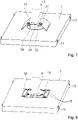
- FIG figure 5 shows an embodiment of a crane support plate 1 with a support leg 9 attached thereto, as in FIG figure 3 shown.
- the crane support plate 1 has a recess 19, the base of which corresponds to the underside of the foot, so that the support foot 9 can be lowered to the bottom of the recess 19, with the foot plate being able to be below, above or flush with the top of the crane support plate 1.
- the crane support plate 1 has a fastening device, which is designed as a threaded rod 21 with detachable nuts 23 that protrudes upwards from the recess 19 .
- the diameter and position of the threaded rods 21 correspond to the holes 17 in the support foot 9, so that the threaded rods 21 protrude through the holes 17 when the support foot 9 is lowered.
- the connection is made by a screw connection, in that the nuts 23 are screwed onto the threaded rods 21 and thus the support foot 9 and the crane support plate 1 are releasably joined together.
- FIG figure 6 shows an embodiment of a crane support plate 1 with a support leg 9 attached thereto, as in FIG figure 3 shown.
- the crane support plate 1 has a recess 19, the base of which corresponds to the underside of the foot, so that the support foot 9 can be lowered therein.
- the connection is made by a fastening device designed as two webs 25 projecting over the support foot 9 .
- the webs 25 are connected to the upper side of the crane support plate 1 and thus hold the support leg 9 in the recess 19 in a form-fitting manner.
- the webs 25 are fastened on one side with bolts 27 on the upper side of the crane support plate 1 so that they can be rotated about the bolts 27 but cannot be detached from the crane support plate 1 .
- the webs 25 are turned away from the recess 19 in order to place the support foot 9 in the recess 19 . Then the webs 25 are positioned over the support leg 9 and releasably fixed on their other side, for example with screws 15. In another exemplary embodiment, the webs 25 are fastened with screws 15 on both sides. In a further exemplary embodiment without a recess 19, the webs 25 would be bent following the shape of the support foot 9, which protrudes over the upper side of the crane support plate 1, in order to form the form-fitting connection.
- connection described above has the advantage that the support leg 9 does not have to have any additional means, such as holes, in order to connect it to the crane support plate 1 .
- FIG figure 7 shows an embodiment of a crane support plate 1 with a support leg 9 attached thereto, as in FIG figure 4 shown.
- the fastening device is designed as a plug-in connection 29, in which the support leg 9 is pushed laterally into a holder 31 which extends over the pushed-in support leg 9.
- the holder 31 has a slot 33 on its upper side, which is designed to correspond to the width of the foot bar.
- the support foot 9 is pushed in along the slot 33 through which the foot rod is guided.
- the unintentional loosening of the crane support plate 1 is prevented by a lock. It is designed, for example, as a web 25 that extends over the slot 33 and is fastened to the holder 31 by screws 15 .
- FIG 8 shows an embodiment of a crane support plate 1, with a support foot 9 attached thereto.
- the fastening device has an adapter device 35, through which the support foot 9 and the surface of the crane support plate 1 are connected.
- the crane support plate 1 has a recess 19 whose base area corresponds to the underside of the adapter device, so that the adapter device 35 can be lowered therein.
- the adapter device 35 is connected to the support leg 9 . In both cases, the connections are made by screws 15.
- other configurations of the adapter device 35 and forms of connection of the crane support plate 1 and support foot 9 to the adapter device 35 for example without a recess 19, are also possible.
- the exemplary connections of crane support plate 1 and support foot 9 described above are also possible between crane support plate 1 and adapter device 35 and between adapter device 35 and support foot 9 .
- the adapter device 35 is interchangeable, so that different adapter devices allow the same crane support plate 1 to be connected to different support leg designs.
Landscapes
- Engineering & Computer Science (AREA)
- Mechanical Engineering (AREA)
- Jib Cranes (AREA)
Abstract
Description
- Die Erfindung betrifft eine Kranabstützplatte für einen Stützfuß an einem Abstützarm eines Mobilkranfahrzeugs.
- Ein Mobilkranfahrzeug ist ein fahrbarer Auslegerkran auf einem Rad- oder Kettenfahrwerk. Für ein sicheres Arbeiten mit einem Mobilkranfahrzeug ist eine Abstützung erforderlich. Die Abstützung des Mobilkranfahrzeugs erfolgt über hydraulische Abstützzylinder, die an ausschwenkbaren und/oder ausfahrbaren Abstützarmen angeordnet sind. An den Abstützzylindern sind auf dem Boden aufsetzbare Stützfüße vorgesehen. Üblicherweise sind vier Abstützarme mit ebenso vielen Stützfüßen vorgesehen. Die Abstützung bewirkt, dass eine hohe Tragfähigkeit erreicht wird, indem die Abstützarme das Kippmoment des Mobilkranfahrzeugs reduzieren, welches durch das Produkt aus Last und Auslegearmlänge bestimmt ist. Zusätzlich wird die effektive Grundfläche vergrößert.
- Für den sicheren und festen Stand des abgestützten Mobilkranfahrzeugs ist erforderlich, dass der Boden den über die Stützfüße einwirken Kräften Stand hält. Ein Absinken des Bodens könnte im schlimmsten Fall zum Kippen des Mobilkranfahrzeugs führen. Für eine bessere Verteilung der Druckkräfte der Stützfüße können Kranabstützplatten eingesetzt werden. Die Kranabstützplatte wird zwischen Boden und Stützfuß positioniert und verteilt die Druckkraft des Stützfuß über eine größere Bodenfläche, um zu erreichen, dass der Boden, auf dem das Mobilkranfahrzeug aufgebaut ist, dem Druck auch bei hoher Belastung noch Stand hält und ein Absinken des Bodens oder gar Kippen des Mobilkranzfahrzeugs vermieden wird. Kleine Kranabstützplatten sind üblicherweise aus Kunststoff und haben Längs- und Querabmessungen die über das ungefähr Doppelte der Stützfußunterseitengröße kaum hinausgehen. Beim Rangieren und Umsetzen des Mobilkranfahrzeugs im Baustellenbereich können sie in einfacher Weise von einer Person an ihre neue Arbeitsposition unter den Stützfüßen getragen werden.
- Im Schwerlastbereich oder bei weichem Boden ist die Handhabung von Kranabstützplatten beim Rangieren und Umsetzen des Mobilkranfahrzeugs wesentlich aufwändiger, da die erforderlichen Kranabstützplatten größer und schwerer sind, um die Verteilung der Druckkräfte der Stützfüße auf einem Untergrund, der zu weich ist, um dem Druck der Stützfüße Stand zu halten, zu verbessern. Eine Kranabstützplatte für den Schwerlastbereich oder für einen weichen Untergrund hat im Vergleich zur Stützfußunterseite eine Grundfläche, die um ein Vielfaches, insbesondere um ein mehr als Zehnfaches größer ist. Um die gewünschte Stabilität zu erreichen, ist die Kranabstützplatte üblicherweise aus Stahl ausgebildet. Eine solche Kranabstützplatte kann mehrere Hundert Kilogramm wiegen und ist nur mit Aufwand und maschineller Hilfe beweglich. Für derartige Kranabstützplatten wird auch die Bezeichnung "Kranmatten" verwendet. Es gibt verschiedene Größen und Formen.
- Wenn das Mobilkranfahrzeug versetzt werden muss, weil sich der Lastschwerpunkt des zu hebenden Gegenstandes verändert, müssen auch die Kranabstützplatten versetzt werden. Beim Rangieren und Umsetzen des Mobilkranfahrzeugs im Baustellenbereich ist das damit einhergehende Verlegen einer schweren Kranabstützplatte mit erheblichem Aufwand verbunden. Bei einem Mobilkranfahrzeug mit vier Stützfüßen werden vier Kranabstützplatten, die jeweils mehrere Hundert Kilogramm wiegen und deshalb nur mit erheblichen Aufwand bewegt werden können, benötigt. Es stellt sich die Aufgabe, eine Vorrichtung anzugeben, die den Aufwand bei der Umpositionierung der Kranabstützplatten reduziert.
- Die Aufgabe wird gelöst durch eine Kranabstützplatte mit den Merkmalen des Anspruchs 1. Die Kranabstützplatte ist im Wesentlichen metallen ausgebildet.
- Sie umfasst eine Befestigungsvorrichtung für einen Stützfuß an einem Abstützarm eines Mobilkranfahrzeugs, die lösbar mit dem Stützfuß verbindbar ist, sodass beim Rangieren des Mobilkranfahrzeugs die vom Stützfuß angehobene Kranabstützplatte am nicht vollständig einfahrbaren und/oder nicht vollständig einschwenkbaren Abstützarm des Mobilkranfahrzeugs hängt.
- Durch die feste Verbindung zwischen der Kranabstützplatte und dem Mobilkranfahrzeug, die vorzugsweise bei allen Stützfüßen und Kranabstützplatten gegeben ist, wird das Rangieren und das daran abschließende erneute Abstützen erheblich erleichtert und erfordert weniger Zeit. Zum Rangieren werden alle Kranabstützplatten durch Anheben der Stützfüße angehoben, und das Mobilkranfahrzeug fährt anschließend auf seine neue Arbeitsposition, senkt die Stützfüße und damit auch die Kranabstützplatten wieder ab bis die Kranabstützplatten Bodenkontakt bekommen, und das Mobilkranfahrzeug kann dann an der neuen Arbeitsposition weiterarbeiten. Da das Rangieren nur im Baustellenbereich erfolgt, ist ein vollständiges Einschwenken und/oder vollständiges Einfahren der Abstützarme nicht erforderlich und wäre angesichts der Größe der schweren Kranabstützplatten auch nicht vollständig möglich.
- Die im Wesentlichen metallene oder metallische Kranabstützplatte hat vorteilhafterweise metallische, insbesondere stählerne Außenwände und eine metallische, insbesondere stählerne Innenstruktur. Kranabstützplatten aus einem Verbundmaterial aus Kunststoff mit lediglich metallischen Faser fallen nicht darunter. Nichtsdestotrotz kann ein geringer Teil der Komponenten der im Wesentlichen metallenen Kranabstützplatte aus anderen Materialien, beispielsweise Kunststoff, sein. Vorteilhafterweise ist die Kranabstützplatte im Wesentlichen stählern und hat eine rechteckige Grundfläche.
- Solche Kranzabstützplatten müssen nicht massiv ausgebildet sein, sondern können beispielsweise mit einer Wabenstruktur im Inneren ausgebildet sein.
- Dennoch kann ihre Grundfläche eine Abmessung von mindestens 1000 mm x 1000 mm haben und das Gewicht kann mindestens 100 kg, üblicherweise jedoch ein Vielfaches davon, betragen. Die Kranzabstützplatten können für Drucklasten von einer oder mehreren Dekatonnen und mehr ausgelegt sein. Die Kranzabstützplatte ist vorteilhafterweise zur Verwendung bei einem Mobilkranfahrzeug mit einer maximalen Krantraglast von mindestens 25 t vorgesehen.
- Wegen der mechanischen Belastung, der die Verbindung ausgesetzt ist, ist die Befestigungsvorrichtung vorteilhafterweise im Wesentlichen oder ganz aus Metall, insbesondere Stahl ausgebildet.
- Die Aufwands- und Zeitersparnis beim Umsetzten des Mobilkranfahrzeugs geht natürlich auch mit einem ökonomischen Vorteil einher, denn die Krandienstleistung kann günstiger angeboten werden beziehungsweise es lässt sich damit bei marktüblichen Preisen eine höhere Gewinnspanne erzielen.
- In einer Ausführung ist eine Ausnehmung in einer Oberseite der Kranzabstützplatte vorgesehen, in der der Stützfuß auf dem Boden der Ausnehmung platzierbar. Form und Größe der Ausnehmung und der Fußunterseite korrespondieren. Auf diese Weise kann der Stützfuß optimal platziert werden. Nichtsdestotrotz gibt es auch Ausführungen von Kranabstützplatten ohne Ausnehmung mit im Wesentlichen, bis auf die Befestigungsvorrichtung, ebener Oberseite.
- In einer Ausführung ist die Befestigungsvorrichtung an der Kranabstützplatte für eine lösbare formschlüssige Verbindung mit dem Stützfuß ausgebildet. Die formschlüssige Verbindung verhindert bis auf mögliches Spiel die Bewegung zwischen den Komponenten, sodass es während des Umsetzens nicht zu einer Verschiebung der Kranabstützplatte oder gar dem Lösen der Kranabstützplatte kommen kann, was die Arbeitssicherheit erhöht und Unfälle vermeidet. Das vertikale Spiel kann deutlich größer sein als Spiel parallel zur Oberseite der Kranabstützplatte, sodass sich der Formschluss auf die Horizontale konzentriert und vornehmlich Bewegungen parallel zur Oberseite der Kranabstützplatte unterbunden werden.
- In einer Ausführung umfasst die Befestigungsvorrichtung eine Schraubverbindung, was eine sichere und feste, aber einfach und leicht lösbare Verbindung bildet.
- In einer Ausführung weist die Befestigungsvorrichtung auf der Kranabstützplatte bewegliche oder von der Kranabstützplatte separate, das heißt von der Kranabstützplatte abnehmbare, Stege auf. Die Stege können auf der Kranabstützplatte befestigt werden, sodass sie sich über den Stützfuß auf der Kranabstützplatte erstrecken und ihn mit der Kranabstützplatte verbinden. Die Stege halten den Stützfuß auf der Kranabstützplatte, sodass eine feste und vorteilhafterweise formschlüssige Verbindung zwischen den Komponenten gebildet wird.
- In einer Ausführung weist die Befestigungsvorrichtung eine Einschiebevorrichtung auf. Der Stützfuß ist so in die Einschiebevorrichtung einführbar, dass bis auf die Bewegung in Gegenrichtung und Spiel keine Bewegung möglich ist. Zur Fixierung des Stützfuß und um unbeabsichtigtes Lösen der Kranabstützplatte zu verhindern, wird die Bewegung aus der Einschiebevorrichtung mit einer Arretierung unterbunden. Als zusätzliche Sicherung kann eine Arretierung auch bei den zuvor erwähnten Befestigungsvorrichtungen vorgesehen sein.
- In einer Ausführung umfasst die Befestigungsvorrichtung eine austauschbare Adaptervorrichtung, die mit dem Stützfuß verbindbar ist, sodass die Adaptervorrichtung zwischen den Stützfuß und die Kranabstützplatte gekoppelt ist. Durch Austausch der Adaptervorrichtung ist die Kranabstützplatte mit verschiedenen Stützfußtypen verbindbar, indem eine mit dem Stützfußtyp korrespondierende Adaptervorrichtung an der Kranabstützplatte befestigt wird.
- Nachfolgend werden einige Ausführungsbeispiele anhand der Zeichnung näher erläutert. Es zeigen:
- Figur 1
- schematisch eine Frontansicht eines Ausführungsbeispiels eines abgestützten Mobilkranfahrzeugs,
- Figur 2
- eine dreidimensionale Darstellung eines Ausführungsbeispiels eines Abstützarmes mit einem Ausführungsbeispiel eines Stützfuß und einem Ausführungsbeispiel einer Kranabstützplatte,
- Figur 3
- eine dreidimensionale Darstellung eines Ausführungsbeispiels eines Stützfuß,
- Figur 4
- eine dreidimensionale Darstellung eines weiteren Ausführungsbeispiels eines Stützfuß,
- Figur 5
- eine dreidimensionale Darstellung eines Ausführungsbeispiels eines Stützfuß und eines Ausführungsbeispiels einer Kranabstützplatte,
- Figur 6
- eine dreidimensionale Darstellung eines weiteren Ausführungsbeispiels eines Stützfuß und eines weiteren Ausführungsbeispiels einer Kranabstützplatte,
- Figur 7
- eine dreidimensionale Darstellung eines weiteren Ausführungsbeispiels eines Stützfuß und eines weiteren Ausführungsbeispiels einer Kranabstützplatte, und
- Figur 8
- eine dreidimensionale Darstellung eines weiteren Ausführungsbeispiels eines Stützfuß und eines weiteren Ausführungsbeispiels einer Kranabstützplatte.
- In den Figuren sind gleiche oder funktional gleichwirkende Komponenten mit den gleichen Bezugszeichen versehen.
-
Figur 1 zeigt schematisch eine Frontansicht eines Ausführungsbeispiels eines Mobilkranfahrzeugs, das über Kranabstützplatten 1 auf dem Boden 3 abgestützt ist. Die Abstützung erfolgt über hydraulische Abstützzylinder 5, die jeweils an ausschwenkbaren und ausfahrbaren Abstützarmen 7 angeordnet ist. Jeweils zwei Abstützarme 7 sind an jeder Seite des Mobilkranfahrzeugs angeordnet, die zur Abstützung ausgeschwenkt und ausgefahren sind. An der Unterseite des Abstützzylinders 5 ist ein Stützfuß 9 angeordnet, der auf der Kranabstützplatte 1 aufsetzt. Durch die ausgeschwenkten und ausgefahrenen Abstützarme 7 wird die effektive Grundfläche des Mobilkranfahrzeugs vergrößert und bewirkt dadurch eine hohe Tragfähigkeit. -
Figur 2 zeigt eine dreidimensionale Darstellung eines Ausführungsbeispiels eines Abstützarmes 7 mit einem hydraulischen Abstützzylinder 5 und einem Stützfuß 9 auf einem Ausführungsbeispiel einer Kranabstützplatte 1. Der ausgeschwenkte und ausgefahrenen Abstützarm 7 erstreckt sich seitlich des Mobilkranfahrzeugs. Der Abstützarm 7 ist als Teleskoparm segmentartig aufgebaut, wobei für die Bewegung der Auszugssegmente 11 hydraulisch erfolgt. An der vom Mobilkranfahrzeug abgewandten Seite des Abstützarms 7 ist der hydraulische Abstützzylinder 5 angeordnet, der ausgebildet ist, den dem Boden 3 zugewandten Stützfuß 9 abzusenken und anzuheben. Die Abstützung erfolgt bei abgesenktem Stützfuß 9. Der Stützfuß 9 umfasst in diesem Ausführungsbeispiel einen pyramidenstumpfförmigen Bereich sowie einen plattenförmigen Bereich mit quadratischer Grundfläche zwischen denen ein Absatz ist. Eine Fußunterseite ist auf der Kranabstützplatte 1 aufgesetzt, die den Druck des Stützfuß 9 über eine Fläche verteilt, die größer ist als die Fußunterseite. - Die Kranabstützplatte 1 ist fest mit dem Stützfuß 9 verbunden, sodass bis auf mögliches Spiel keine Relativbewegung zwischen den miteinander verbundenen Komponenten möglich ist. In diesem Ausführungsbeispiel erfolgt die Verbindung durch eine als Schraubverbindung. Die Befestigungsvorrichtung der Kranabstützplatte 1 umfasst Schrauben 15 und Gewindelöcher in der Kranabstützplatte 1. Die Schrauben 15 greifen durch Löcher im Stützfuß 9 in die hinsichtlich Größe und Position korrespondierenden Gewindelöcher der Kranabstützplatte 1 bilden so eine feste, aber dennoch lösbare Verbindung.
- Die meist sehr hohen Lasten eines Mobilkranfahrzeugs sind oft zu hoch für den Untergrund, sodass der Boden 3 dem Druck des Stützfuß 9 nicht standhalten würde, was zum Absinken des Bodens oder gar Umkippen des Mobilkranfahrzeugs führen könnte. Die Wirkungsweise der Kranabstützplatte 1 beruht auf dem physikalischen Effekt der Vergrößerung der "Kraft pro Fläche". Indem die Fläche vergrößert wird, auf die die Druckkraft wirkt, wird die Kraft, die auf ein Flächenelement wirkt, kleiner. Folgendes Beispiel verdeutlicht dies. Bei einer Last von 50 t, die auf eine Fläche von 0,25 m2 wirkt, ergibt sich eine Flächenlast von 200 t / m2. Wenn 50 t aber auf eine Fläche von 6 m2 wirkt, ergibt sich eine deutlich geringere Flächenlast von 8,33 t / m2.
- Eine große Kranabstützplatte 1 für Schwerlasten und oder weichen Boden 3 ist üblicherweise stählern und nicht massiv ausgebildet. Die rechteckige Grundform weist eine Außenhülle aus Stahl auf. Im Inneren ist beispielsweise eine wabenförmige Struktur, mit der die Last verteilt wird. Nichtsdestotrotz beträgt das Gewicht der Kranabstützplatte 1 mehrere Hundert Kilogramm, sodass sie maschinell an ihren Einsatzort platziert werden muss. Zu diesem Zweck sind im Randbereich Ösen 13 vorgesehen, die einen Transport mit einem Kran erlauben. Statt Ösen können alternative Ausführungsbeispiele von Mitteln, um die Kranabstützplatte anzuheben, sogenannte Anschlagpunkte, vorgesehen sein, beispielsweise Anschweißösen, Rundstahl, Pufferböcke. In einem weiteren Ausführungsbeispiel einer Kranabstützplatte sind Stapelecken vorgesehen, sodass Kranabstützplatten beim Aufeinanderstapeln zwecks Lagerung oder Transport in einfacher Weise ausgerichtet werden können.
- Die Befestigungsvorrichtung der Kranabstützplatte 1 und die durch sie erfolgte feste Verbindung mit dem Stützfuß 9 ermöglicht der Kranführerin, die Kranabstützplatte 1 mittels des hydraulischen Abstützzylinders 5 anzuheben, indem der Stützfuß 9 angehoben wird. Dies kann durch eine elektrische Steuervorrichtung im Mobilkranfahrzeug erfolgen. Auf Grund der Größe der Kranabstützplatte 1 ist es nicht möglich, den Abstützarm 7 vollständig einzufahren oder zurück zu schwenken, sodass die angehobene Kranabstützplatte 1 am zumindest teilweise ausgefahrene und/oder zumindest teilweise ausgeschwenkten Abstützarm 7 hängt. Zum Rangierenden werden alle Kranabstützplatten 1 durch die hydraulischen Abstützzylinder 5 angehoben und das Mobilkranfahrzeug fährt anschließend auf seine neue Arbeitsposition, senkt die Stützfüße 9 und damit auch die Kranabstützplatten 1 wieder ab bis die Kranabstützplatten 1 Bodenkontakt bekommen, und dann kann das Mobilkranfahrzeug an der neuen Arbeitsposition weiterarbeiten. Durch dieses Vorgehen werden Zeit und Aufwand gespart. Die Kranführerin spart viel Zeit, die ansonsten zum zum Bewegen und Ausrichten der Kranabstützplatten 1 unabhängig vom Mobilkranfahrzeug erforderlich gewesen wäre. Spätestens beim Abbauen des Mobilkranfahrzeugs werden die Verbindungen zwischen den Kranabstützplatten 1 und den Stützfüßen 9 gelöst, sodass die Abstützarme 7 wieder eingefahren und eingeschwenkt werden können.
- Es gibt eine Vielzahl von Stützfußausgestaltungen.
Figur 3 zeigt exemplarisch einen Stützfuß 9 mit rechteckiger Fußplatte, die durchgängige Löcher 17 zur Befestigung an einer Kranabstützplatte 1 aufweist.Figur 4 zeigt ein Ausführungsbeispiel eines Stützfuß 9 mit kegelstumpfförmiger Fußplatte, dessen Fußunterseite rund ist. - Die Verbindungsmöglichkeiten durch Ausführungsbeispiele von Befestigungsvorrichtungen an Kranabstützplatten 1 sind vielfältig. Üblicherweise wird angesichts des Gewichts der Kranabstützplatte 1 und zwecks Arbeitssicherheit und Unfallvermeidung eine feste Verbindung zwischen den Komponenten angestrebt, bei der sich die Komponenten bis auf Spiel nicht relativ zueinander bewegen können. Das vertikale Spiel kann deutlich größer sein als Spiel parallel zur Oberseite der Kranabstützplatte, sodass das Spiel parallel zur Oberseite der Kranabstützplatte wesentlich geringer ist. Ausführungsbeispiele können sogar eine Vertikalbewegung der Kranabstützplatte beim Anheben zulassen, bis diese in einer vorgegebenen Position am Stützfuß hängt.
-
Figur 5 zeigt ein Ausführungsbeispiel einer Kranabstützplatte 1 mit einem daran befestigten Stützfuß 9, wie inFigur 3 dargestellt. Die Kranabstützplatte 1 weist eine Ausnehmung 19 auf, deren Grundfläche mit der Fußunterseite korrespondiert, sodass der Stützfuß 9 darin auf den Boden der Ausnehmung 19 absenkbar ist, wobei die Fußplatte unterhalb, oberhalb oder bündig mit der Oberseite der Kranabstützplatte 1 sein kann. Die Kranabstützplatte 1 weist eine Befestigungsvorrichtung auf, die als aus der Ausnehmung 19 nach oben ragende Gewindestangen 21 mit lösbaren Muttern 23 ausgebildet ist. Durchmesser und Position der Gewindestangen 21 korrespondieren mit den Löchern 17 des Stützfuß 9, sodass die Gewindestangen 21 bei abgesenkten Stützfuß 9 durch dessen Löcher 17 ragen. Die Verbindung erfolgt durch eine Schraubverbindung, indem die Muttern 23 auf die Gewindestangen 21 geschraubt werden und somit den Stützfuß 9 und die Kranabstützplatte 1 lösbar zusammenfügen. - Obgleich das zuvor beschriebene und einige der nachfolgenden Ausführungsbeispiele eine Ausnehmung 19 für den Stützfuß 9 aufweisen, ist diese nicht unbedingt erforderlich. Die beschriebenen exemplarischen Verbindungen sind auch ohne Ausnehmung möglich.
-
Figur 6 zeigt ein Ausführungsbeispiel einer Kranabstützplatte 1 mit einem daran befestigten Stützfuß 9, wie inFigur 3 dargestellt. Die Kranabstützplatte 1 weist eine Ausnehmung 19 auf, deren Grundfläche mit der Fußunterseite korrespondiert, sodass der Stützfuß 9 darin absenkbar ist. Die Verbindung erfolgt durch eine als zwei über den Stützfuß 9 ragende Stege 25 ausgebildete Befestigungsvorrichtung. Die Stege 25 sind mit der Oberseite der Kranabstützplatte 1 verbunden und halten so den Stützfuß 9 formschlüssig in der Ausnehmung 19 fest. Als Verliersicherung sind die Stege 25 an einer Seite mit Bolzen 27 an der Oberseite der Kranabstützplatte 1 befestigt, sodass sie um die Bolzen 27 drehbar aber nicht von der Kranabstützplatte 1 lösbar sind. Sie werden von der Ausnehmung 19 weggedreht, um den Stützfuß 9 in die Ausnehmung 19 zu setzen. Dann werden die Stege 25 über dem Stützfuß 9 positioniert und an ihrer anderen Seite lösbar fixiert, beispielsweise mit Schrauben 15. In einem anderen Ausführungsbeispiel sind die Stege 25 an beiden Seiten mit Schrauben 15 befestigt. In einem weiteren Ausführungsbeispiel ohne Ausnehmung 19 wären die Stege 25, der Form des Stützfuß 9, der über die Oberseite der Kranabstützplatte 1 ragt, folgend gebogen, um die formschlüssige Verbindung auszubilden. - Die oben beschriebene Art der Verbindung hat den Vorteil, dass der Stützfuß 9 keine zusätzlich Mittel, wie beispielsweise Löcher, aufweisen muss, um ihn mit der Kranabstützplatte 1 zu verbinden.
-
Figur 7 zeigt ein Ausführungsbeispiel einer Kranabstützplatte 1 mit einem daran befestigten Stützfuß 9, wie inFigur 4 dargestellt. - Die Befestigungsvorrichtung ist als Steckverbindung 29 ausgebildet, bei der der Stützfuß 9 seitlich in eine Halterung 31 geschoben wird, die sich über den eingeschobenen Stützfuß 9 erstreckt. Die Halterung 31 hat an ihrer Oberseite einen Schlitz 33, der korrespondierend mit der Breite der Fußstange ausgebildet ist. Das Einschieben des Stützfuß 9 erfolgt entlang des Schlitzes 33, durch den die Fußstange geführt wird. Das unbeabsichtigte Lösen der Kranabstützplatte 1 wird durch eine Arretierung verhindert. Sie ist beispielhaft als über den Schlitz 33 sich erstreckender Steg 25 ausgebildet, der durch Schrauben 15 an der Halterung 31 befestigt wird.
-
Figur 8 zeigt ein Ausführungsbeispiel einer Kranabstützplatte 1, mit einem daran befestigten Stützfuß 9. Die Befestigungsvorrichtung weist eine Adaptervorrichtung 35 auf, durch die der Stützfuß 9 und die Oberfläche der Kranabstützplatte 1 verbunden sind. Die Kranabstützplatte 1 weit eine Ausnehmung 19 auf, deren Grundfläche mit der Adaptervorrichtungsunterseite korrespondiert, sodass die Adaptervorrichtung 35 darin absenkbar ist. Die Adaptervorrichtung 35 ist mit dem Stützfuß 9 verbunden. Die Verbindungen erfolgen in beiden Fällen durch Schrauben 15. Natürlich sind auch andere Ausgestaltungen der Adaptervorrichtung 35 und Verbindungsformen von Kranabstützplatte 1 und Stützfuß 9 mit der Adaptervorrichtung 35, beispielsweise auch ohne Ausnehmung 19, möglich. Insbesondere die zuvor beschriebenen beispielhaften Verbindungen von Kranabstützplatte 1 und Stützfuß 9 sind auch zwischen Kranabstützplatte 1 und Adaptervorrichtung 35 sowie zwischen Adaptervorrichtung 35 und Stützfuß 9 möglich. - Die Adaptervorrichtung 35 ist austauschbar, sodass verschiedene Adaptervorrichtungen die Verbindung derselben Kranabstützplatte 1 mit verschiedenen Stützfußausführungen erlauben.
- Die vorstehend und die in den Ansprüchen angegebenen sowie die den Abbildungen entnehmbaren Merkmale sind sowohl einzeln als auch in verschiedener Kombination vorteilhaft realisierbar. Die Erfindung ist nicht auf die beschriebenen Ausführungsbeispiele beschränkt, sondern im Rahmen fachmännischen Könnens in mancherlei Weise abwandelbar.
-
- 1
- Kranabstützplatte
- 3
- Boden
- 5
- Abstützzylinder
- 7
- Abstützarm
- 9
- Stützfuß
- 11
- Auszugssegment
- 13
- Öse
- 15
- Schraube
- 17
- Loch
- 19
- Ausnehmung
- 21
- Gewindestange
- 23
- Mutter
- 25
- Steg
- 27
- Bolzen
- 29
- Steckverbindung
- 31
- Halterung
- 33
- Schlitz
- 35
- Adaptervorrichtung
Claims (12)
- Kranabstützplatte (1), die im Wesentlichen metallen ausgebildet ist, mit einer Befestigungsvorrichtung (15, 19, 21, 23, 25, 27, 29, 31, 33, 35) für einen Stützfuß (9) an einem Abstützarm (7) eines Mobilkranzfahrzeugs, wobei die Befestigungsvorrichtung (15, 19, 21, 23, 25, 27, 29, 31, 33, 35) lösbar mit dem Stützfuß (9) verbindbar ist, sodass beim Rangieren des Mobilkranfahrzeugs die vom Stützfuß (9) angehobene Kranabstützplatte (1) am nicht vollständig einfahrbaren und/oder nicht vollständig einschwenkbaren Abstützarm (7) hängt.
- Kranabstützplatte (1) nach Anspruch 1 mit rechteckiger Grundfläche, die stählern ausgebildet ist.
- Kranzabstützplatte (1) nach Anspruch 1 oder 2,
wobei eine Ausnehmung (19) in einer Oberseite der Kranzabstützplatte (1) ist, in der der Stützfuß (9) platzierbar ist. - Kranzabstützplatte (1) nach einem der vorhergehenden Ansprüche,
wobei die Befestigungsvorrichtung (15, 19, 21, 23, 25, 27, 29, 31, 33, 35) ausgebildet ist, eine lösbare formschlüssige Verbindung mit dem Stützfuß (9) zu bilden. - Kranzabstützplatte (1) nach einem der vorhergehenden Ansprüche,
wobei die Befestigungsvorrichtung (15, 19, 21, 23, 25, 27, 29, 31, 33, 35) eine Schraubverbindung umfasst. - Kranabstützplatte (1) nach einem der vorhergehenden Ansprüche,
wobei die Befestigungsvorrichtung (15, 19, 21, 23, 25, 27, 29, 31, 33, 35) auf der Kranabstützplatte (1) bewegliche oder von der Kranabstützplatte (1) lösbare Stege (25) aufweist, die auf der Kranabstützplatte (1) befestigbar sind, sodass die Stege (25) sich über den Stützfuß (9) auf der Kranabstützplatte (1) erstrecken und ihn mit Kranabstützplatte (1) verbinden. - Kranabstützplatte (1) nach einem der vorhergehenden Ansprüche,
wobei die Befestigungsvorrichtung (15, 19, 21, 23, 25, 27, 29, 31, 33, 35) eine Einschiebevorrichtung (19) aufweist. - Kranabstützplatte (1) nach einem der vorhergehenden Ansprüche,
wobei die Befestigungsvorrichtung (15, 19, 21, 23, 25, 27, 29, 31, 33, 35) eine Arretierung aufweist. - Kranabstützplatte (1) nach einem der vorhergehenden Ansprüche,
wobei die Befestigungsvorrichtung (15, 19, 21, 23, 25, 27, 29, 31, 33, 35) eine austauschbare Adaptervorrichtung (35) aufweist, die mit dem Stützfuß (9) verbindbar ist. - Kranzabstützplatte (1) nach einem der vorhergehenden Ansprüche, die nicht massiv ausgebildet ist.
- Kranzabstützplatte (1) nach einem der vorhergehenden Ansprüche,
deren Grundfläche eine Abmessung von mindestens 1000 mm x 1000mm hat und/oder die eine Gewicht von mindestens 100 kg hat. - Kranzabstützplatte (1) nach einem der vorhergehenden Ansprüche zur Verwendung bei einem Mobilkranfahrzeug mit einer maximalen Krantraglast von mindestens 25 t.
Applications Claiming Priority (1)
| Application Number | Priority Date | Filing Date | Title |
|---|---|---|---|
| DE102021105957.7A DE102021105957A1 (de) | 2021-03-11 | 2021-03-11 | Kranabstützplatte |
Publications (3)
| Publication Number | Publication Date |
|---|---|
| EP4063311A1 true EP4063311A1 (de) | 2022-09-28 |
| EP4063311C0 EP4063311C0 (de) | 2024-11-20 |
| EP4063311B1 EP4063311B1 (de) | 2024-11-20 |
Family
ID=80735826
Family Applications (1)
| Application Number | Title | Priority Date | Filing Date |
|---|---|---|---|
| EP22161413.4A Active EP4063311B1 (de) | 2021-03-11 | 2022-03-10 | Kranabstützplatte |
Country Status (2)
| Country | Link |
|---|---|
| EP (1) | EP4063311B1 (de) |
| DE (1) | DE102021105957A1 (de) |
Citations (4)
| Publication number | Priority date | Publication date | Assignee | Title |
|---|---|---|---|---|
| JPS4947313U (de) * | 1972-08-01 | 1974-04-25 | ||
| JPS58174052A (ja) * | 1982-04-02 | 1983-10-13 | Japan Metals & Chem Co Ltd | トラツククレ−ンのアウトリガ−ジヤツキ用敷板 |
| US20060267326A1 (en) * | 2005-05-27 | 2006-11-30 | Richard Ronnie J | Storage system for a support mat |
| JP2011168148A (ja) * | 2010-02-18 | 2011-09-01 | Kawamoto Kogyo:Kk | アウトリガー用敷設支持具 |
-
2021
- 2021-03-11 DE DE102021105957.7A patent/DE102021105957A1/de not_active Withdrawn
-
2022
- 2022-03-10 EP EP22161413.4A patent/EP4063311B1/de active Active
Patent Citations (4)
| Publication number | Priority date | Publication date | Assignee | Title |
|---|---|---|---|---|
| JPS4947313U (de) * | 1972-08-01 | 1974-04-25 | ||
| JPS58174052A (ja) * | 1982-04-02 | 1983-10-13 | Japan Metals & Chem Co Ltd | トラツククレ−ンのアウトリガ−ジヤツキ用敷板 |
| US20060267326A1 (en) * | 2005-05-27 | 2006-11-30 | Richard Ronnie J | Storage system for a support mat |
| JP2011168148A (ja) * | 2010-02-18 | 2011-09-01 | Kawamoto Kogyo:Kk | アウトリガー用敷設支持具 |
Also Published As
| Publication number | Publication date |
|---|---|
| DE102021105957A1 (de) | 2022-09-15 |
| EP4063311C0 (de) | 2024-11-20 |
| EP4063311B1 (de) | 2024-11-20 |
Similar Documents
| Publication | Publication Date | Title |
|---|---|---|
| EP2218836B1 (de) | Fahrzeug, insbesondere Baufahrzeug | |
| DE102015006117B4 (de) | Verfahren zum Betrieb eines Krans und Kran | |
| DE2254886A1 (de) | Hubstapler mit abnehmbarer gabel | |
| DE202021106818U1 (de) | Mobilkran mit einer Gegengewichtsvorrichtung | |
| EP2864548B1 (de) | Bodenverdichtungsgerät | |
| DE102014012661B4 (de) | Verfahren zum Betrieb eines Krans und Kran | |
| DE10019863B4 (de) | Fahrzeugkran | |
| EP2423147A1 (de) | Anordnung zum Wenden einer Last | |
| DE202019106049U1 (de) | Schwerlast-Prüfgewichteinheit zur Belastungsprüfung von Krananlagen | |
| DE3742296C2 (de) | ||
| EP4086218A1 (de) | Abspannsystem und -verfahren für einen mobilkran-teleskopausleger | |
| EP4063311B1 (de) | Kranabstützplatte | |
| DE102020123821B3 (de) | Ballastvorrichtung und Mobilkran mit einer solchen | |
| DE202017103323U1 (de) | Hebevorrichtung für eine Last | |
| EP3995436B1 (de) | Mobilkran mit höhenverstellbarem oberwagenballast | |
| DE102016120030A1 (de) | Hebevorrichtung für eine Last | |
| DE202021101235U1 (de) | Kranabstützplatte | |
| DE102020118775B4 (de) | Mobilkran mit Abstützvorrichtung | |
| DE102022105934B4 (de) | Mobilkran mit einer Gegengewichtsvorrichtung | |
| DE102023109566B4 (de) | Mobilkran mit Gegengewichtsvorrichtung, Gegengewichtsvorrichtung sowie Verfahren zur Montage einer solchen | |
| EP0622327A1 (de) | Lasttraverse | |
| DE10061330B4 (de) | Kranfahrzeug mit zwei Hubwerken | |
| DE102023117808A1 (de) | Kran mit Derrickballast | |
| EP3992028A2 (de) | System und verfahren zur kopplung eines arbeitsgeräts an einem fahrzeug | |
| DE1531222C (de) | Gegengewicht Anhebevorrichtung im drehbaren Oberwagen eines fahrbaren Krans oder eines anderen, eine auskragende Last aufweisenden Fahrzeugs |
Legal Events
| Date | Code | Title | Description |
|---|---|---|---|
| PUAI | Public reference made under article 153(3) epc to a published international application that has entered the european phase |
Free format text: ORIGINAL CODE: 0009012 |
|
| STAA | Information on the status of an ep patent application or granted ep patent |
Free format text: STATUS: THE APPLICATION HAS BEEN PUBLISHED |
|
| AK | Designated contracting states |
Kind code of ref document: A1 Designated state(s): AL AT BE BG CH CY CZ DE DK EE ES FI FR GB GR HR HU IE IS IT LI LT LU LV MC MK MT NL NO PL PT RO RS SE SI SK SM TR |
|
| STAA | Information on the status of an ep patent application or granted ep patent |
Free format text: STATUS: REQUEST FOR EXAMINATION WAS MADE |
|
| 17P | Request for examination filed |
Effective date: 20230328 |
|
| RBV | Designated contracting states (corrected) |
Designated state(s): AL AT BE BG CH CY CZ DE DK EE ES FI FR GB GR HR HU IE IS IT LI LT LU LV MC MK MT NL NO PL PT RO RS SE SI SK SM TR |
|
| GRAP | Despatch of communication of intention to grant a patent |
Free format text: ORIGINAL CODE: EPIDOSNIGR1 |
|
| STAA | Information on the status of an ep patent application or granted ep patent |
Free format text: STATUS: GRANT OF PATENT IS INTENDED |
|
| GRAJ | Information related to disapproval of communication of intention to grant by the applicant or resumption of examination proceedings by the epo deleted |
Free format text: ORIGINAL CODE: EPIDOSDIGR1 |
|
| STAA | Information on the status of an ep patent application or granted ep patent |
Free format text: STATUS: REQUEST FOR EXAMINATION WAS MADE |
|
| INTG | Intention to grant announced |
Effective date: 20240619 |
|
| GRAP | Despatch of communication of intention to grant a patent |
Free format text: ORIGINAL CODE: EPIDOSNIGR1 |
|
| STAA | Information on the status of an ep patent application or granted ep patent |
Free format text: STATUS: GRANT OF PATENT IS INTENDED |
|
| INTC | Intention to grant announced (deleted) | ||
| INTG | Intention to grant announced |
Effective date: 20240729 |
|
| GRAS | Grant fee paid |
Free format text: ORIGINAL CODE: EPIDOSNIGR3 |
|
| GRAA | (expected) grant |
Free format text: ORIGINAL CODE: 0009210 |
|
| STAA | Information on the status of an ep patent application or granted ep patent |
Free format text: STATUS: THE PATENT HAS BEEN GRANTED |
|
| AK | Designated contracting states |
Kind code of ref document: B1 Designated state(s): AL AT BE BG CH CY CZ DE DK EE ES FI FR GB GR HR HU IE IS IT LI LT LU LV MC MK MT NL NO PL PT RO RS SE SI SK SM TR |
|
| REG | Reference to a national code |
Ref country code: GB Ref legal event code: FG4D Free format text: NOT ENGLISH |
|
| REG | Reference to a national code |
Ref country code: CH Ref legal event code: EP |
|
| REG | Reference to a national code |
Ref country code: DE Ref legal event code: R096 Ref document number: 502022002142 Country of ref document: DE |
|
| REG | Reference to a national code |
Ref country code: IE Ref legal event code: FG4D Free format text: LANGUAGE OF EP DOCUMENT: GERMAN |
|
| U01 | Request for unitary effect filed |
Effective date: 20241219 |
|
| U07 | Unitary effect registered |
Designated state(s): AT BE BG DE DK EE FI FR IT LT LU LV MT NL PT RO SE SI Effective date: 20250109 |
|
| PG25 | Lapsed in a contracting state [announced via postgrant information from national office to epo] |
Ref country code: IS Free format text: LAPSE BECAUSE OF FAILURE TO SUBMIT A TRANSLATION OF THE DESCRIPTION OR TO PAY THE FEE WITHIN THE PRESCRIBED TIME-LIMIT Effective date: 20250320 Ref country code: HR Free format text: LAPSE BECAUSE OF FAILURE TO SUBMIT A TRANSLATION OF THE DESCRIPTION OR TO PAY THE FEE WITHIN THE PRESCRIBED TIME-LIMIT Effective date: 20241120 |
|
| PG25 | Lapsed in a contracting state [announced via postgrant information from national office to epo] |
Ref country code: ES Free format text: LAPSE BECAUSE OF FAILURE TO SUBMIT A TRANSLATION OF THE DESCRIPTION OR TO PAY THE FEE WITHIN THE PRESCRIBED TIME-LIMIT Effective date: 20241120 |
|
| PG25 | Lapsed in a contracting state [announced via postgrant information from national office to epo] |
Ref country code: NO Free format text: LAPSE BECAUSE OF FAILURE TO SUBMIT A TRANSLATION OF THE DESCRIPTION OR TO PAY THE FEE WITHIN THE PRESCRIBED TIME-LIMIT Effective date: 20250220 |
|
| PG25 | Lapsed in a contracting state [announced via postgrant information from national office to epo] |
Ref country code: GR Free format text: LAPSE BECAUSE OF FAILURE TO SUBMIT A TRANSLATION OF THE DESCRIPTION OR TO PAY THE FEE WITHIN THE PRESCRIBED TIME-LIMIT Effective date: 20250221 |
|
| PG25 | Lapsed in a contracting state [announced via postgrant information from national office to epo] |
Ref country code: PL Free format text: LAPSE BECAUSE OF FAILURE TO SUBMIT A TRANSLATION OF THE DESCRIPTION OR TO PAY THE FEE WITHIN THE PRESCRIBED TIME-LIMIT Effective date: 20241120 |
|
| PG25 | Lapsed in a contracting state [announced via postgrant information from national office to epo] |
Ref country code: RS Free format text: LAPSE BECAUSE OF FAILURE TO SUBMIT A TRANSLATION OF THE DESCRIPTION OR TO PAY THE FEE WITHIN THE PRESCRIBED TIME-LIMIT Effective date: 20250220 |
|
| U20 | Renewal fee for the european patent with unitary effect paid |
Year of fee payment: 4 Effective date: 20250409 |
|
| PG25 | Lapsed in a contracting state [announced via postgrant information from national office to epo] |
Ref country code: SM Free format text: LAPSE BECAUSE OF FAILURE TO SUBMIT A TRANSLATION OF THE DESCRIPTION OR TO PAY THE FEE WITHIN THE PRESCRIBED TIME-LIMIT Effective date: 20241120 |
|
| PGFP | Annual fee paid to national office [announced via postgrant information from national office to epo] |
Ref country code: CH Payment date: 20250401 Year of fee payment: 4 |
|
| PG25 | Lapsed in a contracting state [announced via postgrant information from national office to epo] |
Ref country code: SK Free format text: LAPSE BECAUSE OF FAILURE TO SUBMIT A TRANSLATION OF THE DESCRIPTION OR TO PAY THE FEE WITHIN THE PRESCRIBED TIME-LIMIT Effective date: 20241120 |
|
| PG25 | Lapsed in a contracting state [announced via postgrant information from national office to epo] |
Ref country code: CZ Free format text: LAPSE BECAUSE OF FAILURE TO SUBMIT A TRANSLATION OF THE DESCRIPTION OR TO PAY THE FEE WITHIN THE PRESCRIBED TIME-LIMIT Effective date: 20241120 |
|
| PLBE | No opposition filed within time limit |
Free format text: ORIGINAL CODE: 0009261 |
|
| STAA | Information on the status of an ep patent application or granted ep patent |
Free format text: STATUS: NO OPPOSITION FILED WITHIN TIME LIMIT |
|
| PG25 | Lapsed in a contracting state [announced via postgrant information from national office to epo] |
Ref country code: MC Free format text: LAPSE BECAUSE OF FAILURE TO SUBMIT A TRANSLATION OF THE DESCRIPTION OR TO PAY THE FEE WITHIN THE PRESCRIBED TIME-LIMIT Effective date: 20241120 |
|
| 26N | No opposition filed |
Effective date: 20250821 |
|
| PG25 | Lapsed in a contracting state [announced via postgrant information from national office to epo] |
Ref country code: IE Free format text: LAPSE BECAUSE OF NON-PAYMENT OF DUE FEES Effective date: 20250310 |
|
| REG | Reference to a national code |
Ref country code: CH Ref legal event code: U11 Free format text: ST27 STATUS EVENT CODE: U-0-0-U10-U11 (AS PROVIDED BY THE NATIONAL OFFICE) Effective date: 20260401 |
|
| U20 | Renewal fee for the european patent with unitary effect paid |
Year of fee payment: 5 Effective date: 20260331 |