EP4063602B1 - Fenêtre oscillante basculante ou porte oscillante basculante pourvue de palier libre inférieur - Google Patents
Fenêtre oscillante basculante ou porte oscillante basculante pourvue de palier libre inférieur Download PDFInfo
- Publication number
- EP4063602B1 EP4063602B1 EP22162207.9A EP22162207A EP4063602B1 EP 4063602 B1 EP4063602 B1 EP 4063602B1 EP 22162207 A EP22162207 A EP 22162207A EP 4063602 B1 EP4063602 B1 EP 4063602B1
- Authority
- EP
- European Patent Office
- Prior art keywords
- window
- pin
- frame
- door according
- door
- Prior art date
- Legal status (The legal status is an assumption and is not a legal conclusion. Google has not performed a legal analysis and makes no representation as to the accuracy of the status listed.)
- Active
Links
Images





Classifications
-
- E—FIXED CONSTRUCTIONS
- E05—LOCKS; KEYS; WINDOW OR DOOR FITTINGS; SAFES
- E05D—HINGES OR SUSPENSION DEVICES FOR DOORS, WINDOWS OR WINGS
- E05D15/00—Suspension arrangements for wings
- E05D15/48—Suspension arrangements for wings allowing alternative movements
- E05D15/52—Suspension arrangements for wings allowing alternative movements for opening about a vertical as well as a horizontal axis
- E05D15/5217—Tilt-lock devices
-
- E—FIXED CONSTRUCTIONS
- E05—LOCKS; KEYS; WINDOW OR DOOR FITTINGS; SAFES
- E05C—BOLTS OR FASTENING DEVICES FOR WINGS, SPECIALLY FOR DOORS OR WINDOWS
- E05C9/00—Arrangements of simultaneously actuated bolts or other securing devices at well-separated positions on the same wing
- E05C9/06—Arrangements of simultaneously actuated bolts or other securing devices at well-separated positions on the same wing with three or more sliding bars
- E05C9/063—Arrangements of simultaneously actuated bolts or other securing devices at well-separated positions on the same wing with three or more sliding bars extending along three or more sides of the wing or frame
- E05C9/066—Locks for windows or doors specially adapted for tilt and turn
-
- E—FIXED CONSTRUCTIONS
- E05—LOCKS; KEYS; WINDOW OR DOOR FITTINGS; SAFES
- E05C—BOLTS OR FASTENING DEVICES FOR WINGS, SPECIALLY FOR DOORS OR WINDOWS
- E05C9/00—Arrangements of simultaneously actuated bolts or other securing devices at well-separated positions on the same wing
- E05C9/18—Details of fastening means or of fixed retaining means for the ends of bars
- E05C9/1808—Keepers
-
- E—FIXED CONSTRUCTIONS
- E05—LOCKS; KEYS; WINDOW OR DOOR FITTINGS; SAFES
- E05D—HINGES OR SUSPENSION DEVICES FOR DOORS, WINDOWS OR WINGS
- E05D15/00—Suspension arrangements for wings
- E05D15/48—Suspension arrangements for wings allowing alternative movements
- E05D15/52—Suspension arrangements for wings allowing alternative movements for opening about a vertical as well as a horizontal axis
-
- E—FIXED CONSTRUCTIONS
- E05—LOCKS; KEYS; WINDOW OR DOOR FITTINGS; SAFES
- E05Y—INDEXING SCHEME ASSOCIATED WITH SUBCLASSES E05D AND E05F, RELATING TO CONSTRUCTION ELEMENTS, ELECTRIC CONTROL, POWER SUPPLY, POWER SIGNAL OR TRANSMISSION, USER INTERFACES, MOUNTING OR COUPLING, DETAILS, ACCESSORIES, AUXILIARY OPERATIONS NOT OTHERWISE PROVIDED FOR, APPLICATION THEREOF
- E05Y2900/00—Application of doors, windows, wings or fittings thereof
- E05Y2900/10—Application of doors, windows, wings or fittings thereof for buildings or parts thereof
- E05Y2900/13—Type of wing
- E05Y2900/132—Doors
-
- E—FIXED CONSTRUCTIONS
- E05—LOCKS; KEYS; WINDOW OR DOOR FITTINGS; SAFES
- E05Y—INDEXING SCHEME ASSOCIATED WITH SUBCLASSES E05D AND E05F, RELATING TO CONSTRUCTION ELEMENTS, ELECTRIC CONTROL, POWER SUPPLY, POWER SIGNAL OR TRANSMISSION, USER INTERFACES, MOUNTING OR COUPLING, DETAILS, ACCESSORIES, AUXILIARY OPERATIONS NOT OTHERWISE PROVIDED FOR, APPLICATION THEREOF
- E05Y2900/00—Application of doors, windows, wings or fittings thereof
- E05Y2900/10—Application of doors, windows, wings or fittings thereof for buildings or parts thereof
- E05Y2900/13—Type of wing
- E05Y2900/148—Windows
Definitions
- the invention relates to a window or a door with a frame and a tiltable and pivotable sash.
- Every tilt-and-turn sash requires at least 2 bearing points on the lower side of the sash to enable tilting around a tilt axis.
- a bearing point is usually a fixed bearing, i.e. a corner bearing, which enables the tilt bearing (horizontal axis) of the sash in addition to the lower pivot bearing (vertical axis).
- This corner bearing is located below the scissor bearing, which forms the upper pivot bearing.
- the second tilt bearing point on a tilt-and-turn sash is solved by a loose bearing. This loose bearing is available in various designs. A simple form of the loose bearing is described here.
- the DE 1 003 084 B discloses a tiltable and pivotable window with a support plate that can be moved by a drive rod latch to grip around a support roller.
- the DE 2 243 916 A1 discloses a tilt bolt lock with a latch pocket on the frame, into which a latch attachment on the sash side can be inserted when tilting.
- Other tilt bolt lock fittings with a corresponding pocket are available from the DE 2 255 042 A1 and the DE 7 149 173 U became known.
- the DE 6 926 148 U discloses a fitting for tilt-and-turn windows in which a sash-side pin engages behind a locking piece mounted on the horizontal beam of a window frame in the tilt position.
- the DE 10 2008 007 095 A1 discloses a tilt-and-turn fitting with a holding element and a locking element, wherein both the holding element and the locking element are designed like stud bolts.
- the DE 10 2012 218 887 A1 and DE 201 14 422 U1 each reveal a locking piece with a guide rail.
- the DE 75 28 905 U discloses a tilt-and-turn fitting with a joint-forming pin which, in the tilt position, snaps into a recess of a fitting that can be connected to the frame.
- a tilt-and-turn fitting has become known in which a tilt pin bearing and a tilt pin interact in such a way that when the fitting is adjusted from the turn to the tilt position, the corner of a sash containing the tilt pin is displaced in the opening direction with respect to a frame.
- the object of the invention is thus achieved by a window or a door with a frame, a tiltable and pivotable sash, a locking piece arranged on a vertical beam of the frame and a drive rod with a pin that can engage behind the locking piece to form a joint for tilting, wherein the center of the pin in the tilt position has a distance of between 4 mm and 29 mm to the top of the rebate of the frame.
- the pin is located approximately at the height of a horizontal corner bearing axis, so that when the sash is tilted, high contact pressure from a sash overhang on the frame can be avoided.
- the pin engages behind the locking piece in a horizontal direction.
- the locking piece serves as a tilting anchor for the pin.
- the center of the tenon in the lowest position preferably has a minimum distance of 4mm, especially 8mm, when the sash is resting on the frame.
- the center of the tenon in the lowest position has a maximum distance of 15mm to the top of the rebate of the frame when the sash is resting on the frame.
- the tenon (bolt) is therefore in a particularly low position in its lowest position.
- the pin can preferably be moved by the drive rod (push rod) with a linear movement in one direction from the closed position to the turn-open position and from the turn-open position to the tilt position.
- the sash has a turn-tilt standard closing sequence.
- the lowest position of the pin corresponds to the tilt position.
- the center of the pin preferably has a horizontal distance of 9 mm or 13 mm to the front of the frame. In the case of a horizontal distance of 9 mm to the front of the frame, the maximum distance of the center of the pin is preferably 12 mm to the top of the rebate of the frame.
- the sash has a tilt-first closing sequence.
- this tilt-first closing sequence the lowest position of the pin corresponds to the rotary opening position.
- the pin can be moved by the drive rod with a linear movement in one direction from the closed position to the tilt position and from the tilt position to the rotary opening position.
- the center of the pin preferably has a horizontal distance of 13 mm from the front of the frame.
- the rebate area refers in particular to the inner circumferential area between the frame and the sash frame.
- the top of the rebate of the frame is understood to mean in particular the highest point of the frame in the rebate area - apart from any seal that may be present.
- top, bottom, inside, outside refers to the installed state of the window or door.
- closed position refers to the positions of the pin on the locking piece as well as to the positions of the sash and the window or door.
- the drive rod and/or the pin protrude downwards over the underside of the rebate of the sash in the tilt position when the sash is resting against the frame.
- the underside of the sash's rebate is understood to mean in particular the lowest point of the sash frame in the rebate area - apart from any seal that may be present.
- the underside of the sash's rebate is preferably located adjacent to the fitting part groove.
- the sash can have a handle and a gear to convert a pivoting movement of the handle into a linear movement of the drive rod.
- the drive rod is preferably provided on the gear side of the sash.
- the window or door may have an electric drive to move the drive rod.
- the locking piece can have a first contact web, which the pin engages behind in the tilted position. This enables a particularly simple design of the locking piece.
- the first contact bar can be tapered towards the top, with the pin engaging behind the first contact bar in the gap ventilation position at the tapered point.
- the wall of the contact bar is partially This allows a gap ventilation position to be provided for the window or door in a particularly simple construction. The higher the pin is moved in the vertical direction, the more play the sash has outwards away from the frame side. In addition, the provision of the gap ventilation position prevents the sash from being lifted out in the tilt position.
- the pin in the case of the standard turn-tilt closing sequence, can be moved by the drive rod into the following positions one after the other: closed position, turn-open position, gap ventilation position, tilt position.
- the locking piece can have a second contact bar, which the pin engages behind in the closed position.
- the locking piece can have a through hole between the first contact bar and the second contact bar, through which the pin can pass the locking piece in the rotary opening position.
- the locking piece can therefore be designed in a butterfly shape. This further simplifies the structural design and manufacture of the locking piece.
- the locking piece can be used for left-hand and right-hand stop if the locking piece is mirror-symmetrical, in particular mirror-symmetrical to a central plane running perpendicular to its longitudinal axis.
- the locking piece is also preferably designed without a slot and/or as a single piece (one-piece). Due to the slot-free design, the locking piece is open on one long side and is only gripped by the pin on the opposite long side. This makes the locking piece particularly easy to manufacture.
- the window or door may have an angled corner connector for attaching a central post.
- the corner connector may protrude beyond the fiberglass edge.
- the locking piece is preferably designed to be particularly narrow.
- the width of the locking piece is particularly preferably less than 18mm, in particular less than 17mm, preferably less than 16mm. This measure also makes the locking piece particularly material-saving.
- the pin can be designed in the form of a mushroom-head pin and the locking piece can have a rear handle that can be gripped behind the mushroom head. This makes the window or door particularly burglar-proof.
- the pin can be arranged eccentrically on the drive rod. This allows the contact pressure of the sash on the frame to be adjusted in the closed position.
- the pin can be riveted to the drive rod in order to enable a particularly simple structural attachment of the pin to the drive rod.
- the pin is cylindrical.
- the pin can be arranged in a T-shape on the drive rod.
- the pin is thus arranged straight on the drive rod, does not form a Z shape with the drive rod and can therefore absorb particularly large forces.
- the window or door can have a mounting bracket arranged at the corner of the sash to guide the drive rod.
- the mounting bracket (connecting bracket / corner connector) enables the drive rod and the pin to be guided securely in the corner of the sash.
- the mounting bracket can be attached to a horizontal lower wing spar using a vertically aligned screw.
- the screw is therefore not covered by the drive rod and is easily accessible for a fitter.
- the mounting bracket can have a support surface on the underside to support the sash on the top of a horizontal lower frame beam. If the sash sags or sinks, the sash can support itself on the frame when closing and can be reliably guided into the closed position.
- the window or door can have a corner drive coupled to the drive rod and a central lock coupled to the corner drive.
- the window or door can include a corner bearing with a horizontal corner bearing axis at a lower wing corner.
- the corner bearing axis is preferably designed to be immovable in the vertical direction.
- a faceplate bar on the sash has a horizontal support for the run-up on the locking piece, in particular for the run-up on the upper side of the second contact web.
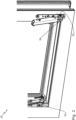
- Fig. 1 shows a window 10 with a frame (fixed frame) 12 and a sash 14, the sash 14 in Fig. 1 for reasons of clarity is largely hidden and only indicated by dashed lines (see also Fig. 11 ).
- the wing 14 is at least lockable, rotatable and tiltable (in Fig. 1 the rotary opening position is shown).
- the sash 14 has a drive rod 16 on which a pin 18 is arranged.
- the pin 18 is intended to engage behind a locking piece 20.
- the locking piece 20 is arranged on a vertical frame beam 22.
- the pin 18 is arranged vertically movable on a vertical sash beam 24 .
- the locking piece 20 and the pin 18 form a loose bearing 25.
- the sash 14 is held on the horizontally opposite sash corner by a corner bearing 26, here in the form of a fixed bearing, on the frame 12.
- the drive rod 16 is held on the sash 14 by a mounting bracket 28.
- the mounting bracket 28 is fastened to a horizontal sash beam 32 by a vertical screw 30.
- the mounting bracket 28 can have a lower run-on surface 33 for support on an upper side of a horizontal lower frame beam 34 .
- Fig. 2 shows the window 10 in the tilt position.
- Fig. 2 it is evident that the corner bearing 26 has a horizontal corner bearing axis 35.
- the horizontal corner bearing axis 35 is vertically offset from the tilt axis of the pin 18 in the tilt position. This causes stresses in the sash 14 (see Fig. 11 ), which are, however, significantly reduced according to the invention.
- Fig. 3 shows the window 10 according to Fig. 2 supplemented by a corner deflection 36 and a central lock 38. This also makes it possible to realize large sash widths with the window 10 according to the invention or the door according to the invention.
- the corner deflection 36 and central lock 38 are coupled in terms of movement to the drive rod 16.
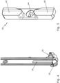
- Fig. 4 shows the drive rod 16 together with the mounting bracket 28 and the pin 18.
- the pin 18 protrudes straight from the drive rod 16.
- Fig. 5 shows the locking piece 20.
- Fig. 5 it can be seen that the locking piece 20 is designed symmetrically. It has a first contact web 40 and a second contact web 42. Between the contact webs 40, 42 there is a through-hole 44 for fastening the locking piece 20 by means of a screw (not shown).
- Fig. 6 shows the window 10 in the closed position. In this position, the pin 18 engages behind the second contact web 42.
- Fig. 7 shows the window 10 according to Fig. 6 in the rotary opening position.
- the pin 18 can pass through a central through opening 46 of the locking piece 20.
- the through opening 46 extends in the width of the locking piece 20.
- Fig. 8 shows the window 10 according to Fig. 7 in the gap ventilation position.
- the sash 14 can be opened slightly (by a few degrees).
- the first contact web 40 has a taper 48.
- the sash 14 can be tilted until the pin 18 rests against the taper 48.
- Fig. 9 finally, the window 10 is shown with fittings in the tilt position. In this position, the pin 18 engages behind the first contact web 40 at a non-tapered point.
- Fig. 10 shows the window 10 according to Fig. 9 with a dimension. From Fig. 10 it is evident that the centre of the tenon 18 in the tilted position is located by the dimension X above the rebate top 50 of the frame 12. Furthermore, the centre of the tenon 18 is located by the dimension Y below the rebate bottom 52 of the sash 14.
- the values for X are preferably between 4mm and 15mm, in particular between 8mm and 15mm.
- the values for Y are preferably between -4mm and 3mm.
- the centre of the tenon 18 is therefore significantly below the rebate underside 52. This enables the sash 14 to be tilted with as little stress as possible and largely prevents a sash overlap 54 from being pressed against the frame 12 when the sash 14 is tilted.
- the center of the pin 18 is offset horizontally by the dimension Z to the front of the frame 12.
- the dimension Z is preferably 9 mm or 13 mm.
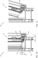
- Fig. 11 shows the window 10 in the tilt position, whereby Fig. 11 It is clear that because the first support web 40 projects far upwards, the pin 18 is not lifted over the first support web 40. Therefore, even in the case of a "swinging tilt", the wing is not lifted.
- Fig. 12 shows a window 10 with a tilt-first closing sequence, with a pin 18 on a sash 14 in the closed position.
- the pin 18 rests against a thickened section 56 of a locking piece 20.
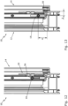
- Fig. 13 shows the window 10 with the pin 18 in the tilt position. Fig. 13 it is evident that the center of the tenon 18 is offset by the dimension X above the top of the rebate 50 of the frame 12 when the sash 14 is in contact with the frame 12.
- the dimension X is preferably 26.5 mm.
- the dimension Z is preferably 13 mm.
- Fig. 14 shows the window 10 with the pin 18 in the tilt position. Fig. 14 It can be seen that the pin 18 rests against a first contact web 40 of the locking piece 20 when the sash 14 is tilted.
- Fig. 15 shows the window 10 with the pin 18 in the rotary opening position. In this lowest position of the pin 18, the pin 18 can pass the locking piece 20, in particular the first contact web 40, preferably on the underside.
- Fig. 16 shows the locking piece 20.
- the locking piece 20 is mirror-symmetrical to a central plane running perpendicular to its longitudinal axis
- the locking piece 20 is therefore suitable for both a left-hand stop and a right-hand stop.
- the locking piece 20 is designed without a slot and in one piece.
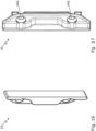
- Fig. 17 also shows the locking piece 20.
- Fig. 17 It can be seen that the locking piece 20 has through-holes 44a, 44b for fastening the locking piece by means of screws (not shown).
- the invention relates in summary to a window 10 or a door with a tiltable and pivotable sash 14.
- a tilt axis of the sash 14 is realized at a sash corner by a horizontally extending pin 18 which, in the tilt position, engages behind a locking piece 20 on a vertical frame part.
- the pin 18 is arranged only between 4 mm and 29 mm above the rebate top 50 of the frame 12 in order to achieve a tension-free tilting of the sash 14 and to avoid a strong pressure of a sash overlap 54 on the frame 12.
Landscapes
- Engineering & Computer Science (AREA)
- Mechanical Engineering (AREA)
- Wing Frames And Configurations (AREA)
Claims (16)
- Fenêtre (10) ou porte comprenant un bâti dormant (12) et un battant basculant et pivotant (14), la fenêtre (10) ou la porte présentant :a) une pièce de fermeture (20) agencée sur un longeron de bâti dormant vertical (22) ;b) une crémone (16) mobile dans sa direction longitudinale sur le battant (14), la crémone (16) présentant un tourillon (18) qui vient en prise avec la pièce de fermeture (20) dans la position de fermeture et vient en prise pour former une articulation dans la position de basculement ;le centre du tourillon (18) présentant une distance (X) comprise entre 4 mm et 29 mm par rapport à la face supérieure de feuillure (50) du bâti dormant (12) dans la position de basculement lorsque le battant (14) repose sur le bâti dormant (12), la crémone (16) et/ou le tourillon (18) faisant saillie vers le bas de la face inférieure de feuillure (52) du battant (14) dans la position de basculement.
- Fenêtre ou porte selon la revendication 1, le centre du tourillon (18) dans sa position la plus basse, lorsque le battant (14) repose sur le bâti dormant (12), présentant une distance (X) comprise entre 4 mm et 15 mm par rapport à la face supérieure de feuillure (50) du bâti dormant (12).
- Fenêtre ou porte selon la revendication 1 ou 2, la fenêtre (10) ou la porte présentant un ordre de fermeture standard oscillo-battant ou un ordre de fermeture de type Tilt-First.
- Fenêtre ou porte selon l'une quelconque des revendications précédentes, le battant (14) présentant une poignée et une transmission pour convertir un mouvement de pivotement de la poignée en un mouvement linéaire de la crémone (16).
- Fenêtre ou porte selon l'une quelconque des revendications précédentes, la pièce de fermeture (20) présentant une première nervure d'appui (40) avec laquelle le tourillon (18) vient en prise dans la position de basculement.
- Fenêtre ou porte selon la revendication 5, la première nervure d'appui (40) étant conçue de manière à être effilée vers le haut vers la face extérieure du bâti dormant, le tourillon (18) venant en prise avec la première nervure d'appui (40) dans la position effilée dans la position d'aération par entrebâillement.
- Fenêtre ou porte selon la revendication 5 ou 6, la pièce de fermeture (20) présentant une seconde nervure d'appui (42) avec laquelle le tourillon (18) vient en prise dans la position de fermeture, la pièce de fermeture (20) présentant une ouverture de passage horizontale (46) entre la première nervure d'appui (40) et la seconde nervure d'appui (42), à travers laquelle le tourillon (18) peut passer dans la pièce de fermeture (20) dans la position de pivotement.
- Fenêtre ou porte selon l'une quelconque des revendications précédentes, la pièce de fermeture (20) étant conçue de manière symétrique par rapport à un plan médian perpendiculaire à son axe longitudinal.
- Fenêtre ou porte selon l'une quelconque des revendications précédentes, la pièce de fermeture (20) pour le guidage du tourillon (18) étant réalisée sans coulisse et/ou étant réalisée d'un seul tenant.
- Fenêtre ou porte selon l'une quelconque des revendications précédentes, le tourillon (18) étant agencé de manière à pouvoir tourner de manière excentrique sur la crémone (16).
- Fenêtre ou porte selon l'une quelconque des revendications précédentes, le tourillon (18) étant agencé en forme de T sur la crémone (16).
- Fenêtre ou porte selon l'une quelconque des revendications précédentes, la fenêtre (10) ou la porte présentant une équerre de montage (28) agencé au niveau d'un coin de battant pour un guidage de la crémone (16).
- Fenêtre ou porte selon la revendication 12, l'équerre de montage (28) étant fixée à un longeron de battant inférieur horizontal (32) par l'intermédiaire d'une vis (30) orientée verticalement.
- Fenêtre ou porte selon la revendication 12 ou 13, l'équerre de montage (28) présentant une surface d'entrée inférieure (33) pour l'appui sur la face supérieure d'un longeron de bâti dormant inférieur horizontal (34).
- Fenêtre ou porte selon l'une quelconque des revendications précédentes, la fenêtre (10) ou la porte présente un renvoi d'angle (36) couplé de manière mobile à la crémone (16) et un verrou central (38) couplé de manière mobile au renvoi d'angle (36).
- Fenêtre ou porte selon l'une quelconque des revendications précédentes, le battant (14) étant monté sur un coin de battant inférieur dans la position de basculement par l'intermédiaire du tourillon (18) et étant monté sur le coin de battant inférieur opposé dans la position de basculement par un palier d'angle (26) de la fenêtre (10) ou de la porte avec un axe de palier d'angle horizontal (35).
Applications Claiming Priority (1)
| Application Number | Priority Date | Filing Date | Title |
|---|---|---|---|
| DE102021202969.8A DE102021202969A1 (de) | 2021-03-25 | 2021-03-25 | Drehkippfenster oder Drehkipptür mit tief liegendem Loslager |
Publications (2)
| Publication Number | Publication Date |
|---|---|
| EP4063602A1 EP4063602A1 (fr) | 2022-09-28 |
| EP4063602B1 true EP4063602B1 (fr) | 2025-01-08 |
Family
ID=80780711
Family Applications (1)
| Application Number | Title | Priority Date | Filing Date |
|---|---|---|---|
| EP22162207.9A Active EP4063602B1 (fr) | 2021-03-25 | 2022-03-15 | Fenêtre oscillante basculante ou porte oscillante basculante pourvue de palier libre inférieur |
Country Status (4)
| Country | Link |
|---|---|
| EP (1) | EP4063602B1 (fr) |
| DE (1) | DE102021202969A1 (fr) |
| ES (1) | ES3014585T3 (fr) |
| PL (1) | PL4063602T3 (fr) |
Family Cites Families (19)
| Publication number | Priority date | Publication date | Assignee | Title |
|---|---|---|---|---|
| DE1003084B (de) | 1954-05-20 | 1957-02-21 | Hans Bilstein | Kippgelenk fuer Schwenk-Kipp-Fluegel von Fenstern, Tueren od. dgl. |
| DE1149636B (de) * | 1956-06-05 | 1963-05-30 | Wilhelm Schaefer & Co | Kippgelenk fuer Kipp-Schwenk-Fluegel von Fenstern, Tueren od. dgl. |
| DE1935885U (de) | 1966-01-25 | 1966-03-31 | Jaeger Frank K G | Schliessgehaeuse fuer zum verriegeln der fluegel von fenstern, tueren od. dgl. dienende kantengetriebe. |
| DE1708312A1 (de) | 1967-09-21 | 1971-05-19 | Bilstein August Fa | Vorderes Kipplager fuer Dreh-Kipp-Fenster,-Tueren od. dgl. |
| DE6926148U (de) | 1969-07-01 | 1969-10-30 | Wilhelm Weidtmann | Verstellbare kippvorrichtung fuer drehkipp-fenster od. dgl. |
| DE7149173U (de) | 1971-12-29 | 1973-02-08 | Fuhr C | Beschlag fuer dreh-kipp-fenster |
| DE2243916C2 (de) | 1972-09-07 | 1985-02-21 | Siegenia-Frank Kg, 5900 Siegen | Kippriegel Verschluß für Drehkippfenster, -türen od.dgl. |
| DE2255042C3 (de) | 1972-11-10 | 1980-04-24 | Siegenia-Frank Kg, 5900 Siegen-Kaan- Marienborn | Kippriegel- und Verschlußvorrichtung für Drehkippflügel-Fenster und -Türen o.dgl |
| DE2445855C2 (de) * | 1974-09-26 | 1983-12-08 | Siegenia-Frank Kg, 5900 Siegen | Sperrvorrichtung an Fenstern, Türen od. dgl. mit zwei in einem Rahmen mit festem Mittelpfosten nebeneinander angeordneten, voneinander unabhängig betätigbare Treibstangenverschlüsse aufweisenden Flügeln |
| DE7528905U (de) | 1975-09-12 | 1976-04-15 | Keller, Eberhard, 7121 Freudental | Verriegelungsgestaenge bei einem fenster u.dgl. |
| FR2330836A1 (fr) * | 1975-11-07 | 1977-06-03 | Ferco Int Usine Ferrures | Dispositif de verrouillage pour fenetres, portes et autres a ouverture oscillo-battante |
| DE2557320A1 (de) * | 1975-12-19 | 1977-06-30 | Ver Baubeschlag Gretsch Co | Riegelvorrichtung fuer kippbare fluegel von fenstern, tueren o.dgl. |
| AT369851B (de) | 1976-06-30 | 1983-02-10 | Hrachowina Bauelemente Prod | Kipplager fuer drehkippfluegel von fenstern od. tueren |
| DE20004941U1 (de) | 2000-03-17 | 2000-06-21 | Schüring GmbH & Co. Fenster-Technologie KG, 53842 Troisdorf | Kippzapfenaufnahme für Kippschließvorrichtung |
| DE20114422U1 (de) | 2001-08-31 | 2001-11-08 | Roto Frank Ag, 70771 Leinfelden-Echterdingen | Beschlag an einem Fenster, einer Tür o.dgl. mit einem Riegelzapfen sowie einem Kippverriegelungsteil |
| DE102006035398A1 (de) | 2006-11-06 | 2008-05-29 | Aug. Winkhaus Gmbh & Co. Kg | Kipplager für ein Fenster, Fenster mit einem solchen Kipplager und Verwendung eines solchen Kipplagers |
| DE102008007095B4 (de) | 2008-02-01 | 2011-07-14 | Roto Frank Ag, 70771 | Dreh-Kipp-Beschlag |
| DE102008021047B4 (de) | 2008-04-26 | 2011-02-10 | Roto Frank Aktiengesellschaft | Beschlag für ein Fenster, eine Tür oder dergleichen sowie Fenster, Tür oder dergleichen mit einem Beschlag und Verfahren zum Verriegeln und Kipplagern einer Flügelecke eines Flügels |
| DE102012218887B4 (de) | 2012-10-17 | 2014-12-04 | Roto Frank Ag | Schließstück für ein Fenster, eine Tür oder dergleichen |
-
2021
- 2021-03-25 DE DE102021202969.8A patent/DE102021202969A1/de active Pending
-
2022
- 2022-03-15 EP EP22162207.9A patent/EP4063602B1/fr active Active
- 2022-03-15 ES ES22162207T patent/ES3014585T3/es active Active
- 2022-03-15 PL PL22162207.9T patent/PL4063602T3/pl unknown
Also Published As
| Publication number | Publication date |
|---|---|
| PL4063602T3 (pl) | 2025-04-28 |
| ES3014585T3 (en) | 2025-04-23 |
| DE102021202969A1 (de) | 2022-09-29 |
| EP4063602A1 (fr) | 2022-09-28 |
Similar Documents
| Publication | Publication Date | Title |
|---|---|---|
| EP4473182B1 (fr) | Agencement de profilé d'une fenêtre ou d'une porte ayant un profilé de châssis/battant, en particulier un profilé de châssis/battant coulissant | |
| EP3102759B1 (fr) | Ferrure d'un battant de fenêtres ou de portes, au moins relevable et coulissant | |
| DE8702660U1 (de) | Fenster- oder Tür-Konstruktion mit einem bewegbar gehaltenen, verriegelbaren Flügel | |
| EP1045092B1 (fr) | Dispositif de sécurité pour une fenêtre et fenêtre avec un tel dispositif de sécurité | |
| EP4573255A1 (fr) | Ensemble profilé d'une fenêtre ou d'une porte présentant un profilé de châssis/battant, en particulier un profilé de châssis/battant coulissant | |
| EP0844348B1 (fr) | Penture pour portes ou fenêtres | |
| EP4063602B1 (fr) | Fenêtre oscillante basculante ou porte oscillante basculante pourvue de palier libre inférieur | |
| EP1678402B1 (fr) | Dispositif pour recevoir le poids d'une porte a un ou deux vantaux d'une armoire electrique | |
| DE9202933U1 (de) | Beschlag für einen um eine etwa mittlere Achse drehbaren Flügel | |
| DE2243916C2 (de) | Kippriegel Verschluß für Drehkippfenster, -türen od.dgl. | |
| EP1425489B1 (fr) | Ferrure oscillobattante | |
| DE19603415C1 (de) | Vorrichtung zur Verriegelung eines zwischen zwei Endstellungen um eine Achse schwenkbaren, in Verschlußstellung befindlichen Bauteils zum Verschließen einer Zugangsöffnung zu einem von Wänden umschlossenen Raum | |
| AT393712B (de) | Schliessplatte fuer fenster- und tuerverschluesse od.dgl. | |
| EP1659241B1 (fr) | Ferrure pour dispositif anti-effraction de fenetre ou de porte a plusieurs vantaux | |
| EP2740865B1 (fr) | Armature de baguette de fermeture ainsi qu'agencement d'armature de baguette de fermeture et fenêtre ou analogue ainsi équipés | |
| EP3444417B1 (fr) | Système de stockage pour ouvertures de bâtiment | |
| EP4685318A1 (fr) | Ferrure avec un pêne auxiliaire, en particulier pour fenêtres ou portes à deux vantaux sans montant central | |
| EP0887501A2 (fr) | Ferrure arrangée en feuillure pour fenêtre, porte ou similaire | |
| DE29800306U1 (de) | Beschlag für einen Flügelrahmen von Fenstern oder Türen | |
| EP2261453B1 (fr) | Fenêtre ou porte | |
| DE29509178U1 (de) | Vertikalführungselement | |
| DE10110631A1 (de) | Kippzapfenaufnahme für Kippschließvorrichtung | |
| DE29602615U1 (de) | Vorrichtung zur Sicherung eines zwischen zwei Endstellungen bewegbaren Bauteils zum Verschließen einer Wandöffnung eines Gebäudes | |
| DE29920160U1 (de) | Dreh-Kipp-Beschlagsystem | |
| DE29513202U1 (de) | Funktionselement |
Legal Events
| Date | Code | Title | Description |
|---|---|---|---|
| PUAI | Public reference made under article 153(3) epc to a published international application that has entered the european phase |
Free format text: ORIGINAL CODE: 0009012 |
|
| STAA | Information on the status of an ep patent application or granted ep patent |
Free format text: STATUS: THE APPLICATION HAS BEEN PUBLISHED |
|
| STAA | Information on the status of an ep patent application or granted ep patent |
Free format text: STATUS: REQUEST FOR EXAMINATION WAS MADE |
|
| AK | Designated contracting states |
Kind code of ref document: A1 Designated state(s): AL AT BE BG CH CY CZ DE DK EE ES FI FR GB GR HR HU IE IS IT LI LT LU LV MC MK MT NL NO PL PT RO RS SE SI SK SM TR |
|
| 17P | Request for examination filed |
Effective date: 20220905 |
|
| RBV | Designated contracting states (corrected) |
Designated state(s): AL AT BE BG CH CY CZ DE DK EE ES FI FR GB GR HR HU IE IS IT LI LT LU LV MC MK MT NL NO PL PT RO RS SE SI SK SM TR |
|
| GRAP | Despatch of communication of intention to grant a patent |
Free format text: ORIGINAL CODE: EPIDOSNIGR1 |
|
| STAA | Information on the status of an ep patent application or granted ep patent |
Free format text: STATUS: GRANT OF PATENT IS INTENDED |
|
| INTG | Intention to grant announced |
Effective date: 20241017 |
|
| GRAS | Grant fee paid |
Free format text: ORIGINAL CODE: EPIDOSNIGR3 |
|
| GRAA | (expected) grant |
Free format text: ORIGINAL CODE: 0009210 |
|
| STAA | Information on the status of an ep patent application or granted ep patent |
Free format text: STATUS: THE PATENT HAS BEEN GRANTED |
|
| AK | Designated contracting states |
Kind code of ref document: B1 Designated state(s): AL AT BE BG CH CY CZ DE DK EE ES FI FR GB GR HR HU IE IS IT LI LT LU LV MC MK MT NL NO PL PT RO RS SE SI SK SM TR |
|
| REG | Reference to a national code |
Ref country code: GB Ref legal event code: FG4D Free format text: NOT ENGLISH |
|
| REG | Reference to a national code |
Ref country code: CH Ref legal event code: EP |
|
| REG | Reference to a national code |
Ref country code: DE Ref legal event code: R096 Ref document number: 502022002608 Country of ref document: DE |
|
| REG | Reference to a national code |
Ref country code: IE Ref legal event code: FG4D Free format text: LANGUAGE OF EP DOCUMENT: GERMAN |
|
| REG | Reference to a national code |
Ref country code: ES Ref legal event code: FG2A Ref document number: 3014585 Country of ref document: ES Kind code of ref document: T3 Effective date: 20250423 |
|
| REG | Reference to a national code |
Ref country code: LT Ref legal event code: MG9D |
|
| REG | Reference to a national code |
Ref country code: NL Ref legal event code: MP Effective date: 20250108 |
|
| PG25 | Lapsed in a contracting state [announced via postgrant information from national office to epo] |
Ref country code: NL Free format text: LAPSE BECAUSE OF FAILURE TO SUBMIT A TRANSLATION OF THE DESCRIPTION OR TO PAY THE FEE WITHIN THE PRESCRIBED TIME-LIMIT Effective date: 20250108 |
|
| PG25 | Lapsed in a contracting state [announced via postgrant information from national office to epo] |
Ref country code: RS Free format text: LAPSE BECAUSE OF FAILURE TO SUBMIT A TRANSLATION OF THE DESCRIPTION OR TO PAY THE FEE WITHIN THE PRESCRIBED TIME-LIMIT Effective date: 20250408 |
|
| PGFP | Annual fee paid to national office [announced via postgrant information from national office to epo] |
Ref country code: ES Payment date: 20250416 Year of fee payment: 4 |
|
| PG25 | Lapsed in a contracting state [announced via postgrant information from national office to epo] |
Ref country code: NO Free format text: LAPSE BECAUSE OF FAILURE TO SUBMIT A TRANSLATION OF THE DESCRIPTION OR TO PAY THE FEE WITHIN THE PRESCRIBED TIME-LIMIT Effective date: 20250408 Ref country code: IS Free format text: LAPSE BECAUSE OF FAILURE TO SUBMIT A TRANSLATION OF THE DESCRIPTION OR TO PAY THE FEE WITHIN THE PRESCRIBED TIME-LIMIT Effective date: 20250508 |
|
| PG25 | Lapsed in a contracting state [announced via postgrant information from national office to epo] |
Ref country code: HR Free format text: LAPSE BECAUSE OF FAILURE TO SUBMIT A TRANSLATION OF THE DESCRIPTION OR TO PAY THE FEE WITHIN THE PRESCRIBED TIME-LIMIT Effective date: 20250108 |
|
| PG25 | Lapsed in a contracting state [announced via postgrant information from national office to epo] |
Ref country code: PT Free format text: LAPSE BECAUSE OF FAILURE TO SUBMIT A TRANSLATION OF THE DESCRIPTION OR TO PAY THE FEE WITHIN THE PRESCRIBED TIME-LIMIT Effective date: 20250508 Ref country code: LV Free format text: LAPSE BECAUSE OF FAILURE TO SUBMIT A TRANSLATION OF THE DESCRIPTION OR TO PAY THE FEE WITHIN THE PRESCRIBED TIME-LIMIT Effective date: 20250108 |
|
| PG25 | Lapsed in a contracting state [announced via postgrant information from national office to epo] |
Ref country code: GR Free format text: LAPSE BECAUSE OF FAILURE TO SUBMIT A TRANSLATION OF THE DESCRIPTION OR TO PAY THE FEE WITHIN THE PRESCRIBED TIME-LIMIT Effective date: 20250409 Ref country code: BG Free format text: LAPSE BECAUSE OF FAILURE TO SUBMIT A TRANSLATION OF THE DESCRIPTION OR TO PAY THE FEE WITHIN THE PRESCRIBED TIME-LIMIT Effective date: 20250108 |
|
| PG25 | Lapsed in a contracting state [announced via postgrant information from national office to epo] |
Ref country code: SE Free format text: LAPSE BECAUSE OF FAILURE TO SUBMIT A TRANSLATION OF THE DESCRIPTION OR TO PAY THE FEE WITHIN THE PRESCRIBED TIME-LIMIT Effective date: 20250108 |
|
| PG25 | Lapsed in a contracting state [announced via postgrant information from national office to epo] |
Ref country code: SM Free format text: LAPSE BECAUSE OF FAILURE TO SUBMIT A TRANSLATION OF THE DESCRIPTION OR TO PAY THE FEE WITHIN THE PRESCRIBED TIME-LIMIT Effective date: 20250108 |
|
| REG | Reference to a national code |
Ref country code: DE Ref legal event code: R097 Ref document number: 502022002608 Country of ref document: DE |
|
| PG25 | Lapsed in a contracting state [announced via postgrant information from national office to epo] |
Ref country code: DK Free format text: LAPSE BECAUSE OF FAILURE TO SUBMIT A TRANSLATION OF THE DESCRIPTION OR TO PAY THE FEE WITHIN THE PRESCRIBED TIME-LIMIT Effective date: 20250108 |
|
| PG25 | Lapsed in a contracting state [announced via postgrant information from national office to epo] |
Ref country code: MC Free format text: LAPSE BECAUSE OF FAILURE TO SUBMIT A TRANSLATION OF THE DESCRIPTION OR TO PAY THE FEE WITHIN THE PRESCRIBED TIME-LIMIT Effective date: 20250108 |
|
| PG25 | Lapsed in a contracting state [announced via postgrant information from national office to epo] |
Ref country code: EE Free format text: LAPSE BECAUSE OF FAILURE TO SUBMIT A TRANSLATION OF THE DESCRIPTION OR TO PAY THE FEE WITHIN THE PRESCRIBED TIME-LIMIT Effective date: 20250108 Ref country code: CZ Free format text: LAPSE BECAUSE OF FAILURE TO SUBMIT A TRANSLATION OF THE DESCRIPTION OR TO PAY THE FEE WITHIN THE PRESCRIBED TIME-LIMIT Effective date: 20250108 |
|
| PG25 | Lapsed in a contracting state [announced via postgrant information from national office to epo] |
Ref country code: RO Free format text: LAPSE BECAUSE OF FAILURE TO SUBMIT A TRANSLATION OF THE DESCRIPTION OR TO PAY THE FEE WITHIN THE PRESCRIBED TIME-LIMIT Effective date: 20250108 |
|
| REG | Reference to a national code |
Ref country code: CH Ref legal event code: H13 Free format text: ST27 STATUS EVENT CODE: U-0-0-H10-H13 (AS PROVIDED BY THE NATIONAL OFFICE) Effective date: 20251024 |
|
| PG25 | Lapsed in a contracting state [announced via postgrant information from national office to epo] |
Ref country code: SK Free format text: LAPSE BECAUSE OF FAILURE TO SUBMIT A TRANSLATION OF THE DESCRIPTION OR TO PAY THE FEE WITHIN THE PRESCRIBED TIME-LIMIT Effective date: 20250108 |
|
| PLBE | No opposition filed within time limit |
Free format text: ORIGINAL CODE: 0009261 |
|
| STAA | Information on the status of an ep patent application or granted ep patent |
Free format text: STATUS: NO OPPOSITION FILED WITHIN TIME LIMIT |
|
| PG25 | Lapsed in a contracting state [announced via postgrant information from national office to epo] |
Ref country code: LU Free format text: LAPSE BECAUSE OF NON-PAYMENT OF DUE FEES Effective date: 20250315 |
|
| REG | Reference to a national code |
Ref country code: BE Ref legal event code: MM Effective date: 20250331 |
|
| 26N | No opposition filed |
Effective date: 20251009 |
|
| PGFP | Annual fee paid to national office [announced via postgrant information from national office to epo] |
Ref country code: IT Payment date: 20250331 Year of fee payment: 4 |
|
| PG25 | Lapsed in a contracting state [announced via postgrant information from national office to epo] |
Ref country code: BE Free format text: LAPSE BECAUSE OF NON-PAYMENT OF DUE FEES Effective date: 20250331 |
|
| PG25 | Lapsed in a contracting state [announced via postgrant information from national office to epo] |
Ref country code: CH Free format text: LAPSE BECAUSE OF NON-PAYMENT OF DUE FEES Effective date: 20250331 |
|
| PG25 | Lapsed in a contracting state [announced via postgrant information from national office to epo] |
Ref country code: IE Free format text: LAPSE BECAUSE OF NON-PAYMENT OF DUE FEES Effective date: 20250315 |
|
| PGFP | Annual fee paid to national office [announced via postgrant information from national office to epo] |
Ref country code: DE Payment date: 20260320 Year of fee payment: 5 |
|
| PGFP | Annual fee paid to national office [announced via postgrant information from national office to epo] |
Ref country code: AT Payment date: 20260301 Year of fee payment: 5 |
|
| PGFP | Annual fee paid to national office [announced via postgrant information from national office to epo] |
Ref country code: FR Payment date: 20260324 Year of fee payment: 5 |
|
| PGFP | Annual fee paid to national office [announced via postgrant information from national office to epo] |
Ref country code: TR Payment date: 20260305 Year of fee payment: 5 |
|
| PGFP | Annual fee paid to national office [announced via postgrant information from national office to epo] |
Ref country code: PL Payment date: 20260227 Year of fee payment: 5 |