EP4063618B1 - Segment d'arc d'aube doté d'un joint à ressort - Google Patents
Segment d'arc d'aube doté d'un joint à ressort Download PDFInfo
- Publication number
- EP4063618B1 EP4063618B1 EP22160037.2A EP22160037A EP4063618B1 EP 4063618 B1 EP4063618 B1 EP 4063618B1 EP 22160037 A EP22160037 A EP 22160037A EP 4063618 B1 EP4063618 B1 EP 4063618B1
- Authority
- EP
- European Patent Office
- Prior art keywords
- platform
- seal
- spar
- arc segment
- fairing
- Prior art date
- Legal status (The legal status is an assumption and is not a legal conclusion. Google has not performed a legal analysis and makes no representation as to the accuracy of the status listed.)
- Active
Links
Images



Classifications
-
- F—MECHANICAL ENGINEERING; LIGHTING; HEATING; WEAPONS; BLASTING
- F01—MACHINES OR ENGINES IN GENERAL; ENGINE PLANTS IN GENERAL; STEAM ENGINES
- F01D—NON-POSITIVE DISPLACEMENT MACHINES OR ENGINES, e.g. STEAM TURBINES
- F01D9/00—Stators
- F01D9/02—Nozzles; Nozzle boxes; Stator blades; Guide conduits, e.g. individual nozzles
- F01D9/04—Nozzles; Nozzle boxes; Stator blades; Guide conduits, e.g. individual nozzles forming ring or sector
- F01D9/041—Nozzles; Nozzle boxes; Stator blades; Guide conduits, e.g. individual nozzles forming ring or sector using blades
-
- F—MECHANICAL ENGINEERING; LIGHTING; HEATING; WEAPONS; BLASTING
- F01—MACHINES OR ENGINES IN GENERAL; ENGINE PLANTS IN GENERAL; STEAM ENGINES
- F01D—NON-POSITIVE DISPLACEMENT MACHINES OR ENGINES, e.g. STEAM TURBINES
- F01D11/00—Preventing or minimising internal leakage of working-fluid, e.g. between stages
- F01D11/003—Preventing or minimising internal leakage of working-fluid, e.g. between stages by packing rings; Mechanical seals
-
- F—MECHANICAL ENGINEERING; LIGHTING; HEATING; WEAPONS; BLASTING
- F01—MACHINES OR ENGINES IN GENERAL; ENGINE PLANTS IN GENERAL; STEAM ENGINES
- F01D—NON-POSITIVE DISPLACEMENT MACHINES OR ENGINES, e.g. STEAM TURBINES
- F01D11/00—Preventing or minimising internal leakage of working-fluid, e.g. between stages
- F01D11/005—Sealing means between non relatively rotating elements
-
- F—MECHANICAL ENGINEERING; LIGHTING; HEATING; WEAPONS; BLASTING
- F01—MACHINES OR ENGINES IN GENERAL; ENGINE PLANTS IN GENERAL; STEAM ENGINES
- F01D—NON-POSITIVE DISPLACEMENT MACHINES OR ENGINES, e.g. STEAM TURBINES
- F01D5/00—Blades; Blade-carrying members; Heating, heat-insulating, cooling or antivibration means on the blades or the members
- F01D5/12—Blades
- F01D5/14—Form or construction
- F01D5/18—Hollow blades, i.e. blades with cooling or heating channels or cavities; Heating, heat-insulating or cooling means on blades
- F01D5/187—Convection cooling
- F01D5/188—Convection cooling with an insert in the blade cavity to guide the cooling fluid, e.g. forming a separation wall
-
- F—MECHANICAL ENGINEERING; LIGHTING; HEATING; WEAPONS; BLASTING
- F01—MACHINES OR ENGINES IN GENERAL; ENGINE PLANTS IN GENERAL; STEAM ENGINES
- F01D—NON-POSITIVE DISPLACEMENT MACHINES OR ENGINES, e.g. STEAM TURBINES
- F01D5/00—Blades; Blade-carrying members; Heating, heat-insulating, cooling or antivibration means on the blades or the members
- F01D5/12—Blades
- F01D5/28—Selecting particular materials; Particular measures relating thereto; Measures against erosion or corrosion
- F01D5/284—Selection of ceramic materials
-
- F—MECHANICAL ENGINEERING; LIGHTING; HEATING; WEAPONS; BLASTING
- F01—MACHINES OR ENGINES IN GENERAL; ENGINE PLANTS IN GENERAL; STEAM ENGINES
- F01D—NON-POSITIVE DISPLACEMENT MACHINES OR ENGINES, e.g. STEAM TURBINES
- F01D9/00—Stators
- F01D9/02—Nozzles; Nozzle boxes; Stator blades; Guide conduits, e.g. individual nozzles
- F01D9/04—Nozzles; Nozzle boxes; Stator blades; Guide conduits, e.g. individual nozzles forming ring or sector
- F01D9/042—Nozzles; Nozzle boxes; Stator blades; Guide conduits, e.g. individual nozzles forming ring or sector fixing blades to stators
-
- F—MECHANICAL ENGINEERING; LIGHTING; HEATING; WEAPONS; BLASTING
- F05—INDEXING SCHEMES RELATING TO ENGINES OR PUMPS IN VARIOUS SUBCLASSES OF CLASSES F01-F04
- F05D—INDEXING SCHEME FOR ASPECTS RELATING TO NON-POSITIVE-DISPLACEMENT MACHINES OR ENGINES, GAS-TURBINES OR JET-PROPULSION PLANTS
- F05D2220/00—Application
- F05D2220/30—Application in turbines
- F05D2220/32—Application in turbines in gas turbines
-
- F—MECHANICAL ENGINEERING; LIGHTING; HEATING; WEAPONS; BLASTING
- F05—INDEXING SCHEMES RELATING TO ENGINES OR PUMPS IN VARIOUS SUBCLASSES OF CLASSES F01-F04
- F05D—INDEXING SCHEME FOR ASPECTS RELATING TO NON-POSITIVE-DISPLACEMENT MACHINES OR ENGINES, GAS-TURBINES OR JET-PROPULSION PLANTS
- F05D2240/00—Components
- F05D2240/10—Stators
- F05D2240/12—Fluid guiding means, e.g. vanes
-
- F—MECHANICAL ENGINEERING; LIGHTING; HEATING; WEAPONS; BLASTING
- F05—INDEXING SCHEMES RELATING TO ENGINES OR PUMPS IN VARIOUS SUBCLASSES OF CLASSES F01-F04
- F05D—INDEXING SCHEME FOR ASPECTS RELATING TO NON-POSITIVE-DISPLACEMENT MACHINES OR ENGINES, GAS-TURBINES OR JET-PROPULSION PLANTS
- F05D2240/00—Components
- F05D2240/55—Seals
-
- F—MECHANICAL ENGINEERING; LIGHTING; HEATING; WEAPONS; BLASTING
- F05—INDEXING SCHEMES RELATING TO ENGINES OR PUMPS IN VARIOUS SUBCLASSES OF CLASSES F01-F04
- F05D—INDEXING SCHEME FOR ASPECTS RELATING TO NON-POSITIVE-DISPLACEMENT MACHINES OR ENGINES, GAS-TURBINES OR JET-PROPULSION PLANTS
- F05D2300/00—Materials; Properties thereof
- F05D2300/60—Properties or characteristics given to material by treatment or manufacturing
- F05D2300/603—Composites; e.g. fibre-reinforced
- F05D2300/6033—Ceramic matrix composites [CMC]
Definitions
- a gas turbine engine typically includes a fan section, a compressor section, a combustor section and a turbine section. Air entering the compressor section is compressed and delivered into the combustion section where it is mixed with fuel and ignited to generate a high-speed exhaust gas flow. The high-speed exhaust gas flow expands through the turbine section to drive the compressor and the fan section.
- the compressor section may include low and high pressure compressors, and the turbine section may also include low and high pressure turbines.
- Airfoils in the turbine section are typically formed of a superalloy and may include thermal barrier coatings to extend temperature capability and lifetime. Ceramic matrix composite (“CMC”) materials are also being considered for airfoils. Among other attractive properties, CMCs have high temperature resistance. Despite this attribute, however, there are unique challenges to implementing CMCs in airfoils.
- US 2008/279679 discloses a multivane segment mounting arrangement for a gas turbine.
- a vane arc segment is provided in accordance with claim 1.
- the spring seal includes a rope seal disposed in the channel.
- the base plate includes a plurality of through-holes that open into the channel.
- the base plate defines a plurality of upstanding spring tabs.
- each of the upstanding spring tabs includes a hooked tip that defines a bearing surface.
- each of the upstanding spring tabs has an acute bend.
- the upstanding spring tabs bear against the spar platform and the backing plate bears against the fairing platform.
- the backing plate has a skirt portion that, relative to the opening, extends outwardly beyond the base plate.
- the seal plate includes a projecting arm that overlaps an additional, adjacent seal.
- the spring seal includes a seal plate defining an opening through which a baffle extends, and the seal plate is welded to the baffle around the opening.
- a gas turbine engine according to an example of the present invention is provided in accordance with claim 11.
- the base plate includes a plurality of through-holes that open into the channel.
- the base plate defines a plurality of upstanding spring tabs.
- Each of the upstanding spring tabs has an acute bend and includes a hooked tip that defines a bearing surface.
- the upstanding spring tabs bear against the spar platform, and the backing plate bears against the fairing platform.
- the backing plate has a skirt portion that, relative to the opening, extends outwardly beyond the base plate.
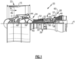
- FIG. 1 schematically illustrates a gas turbine engine 20.
- the gas turbine engine 20 is disclosed herein as a two-spool turbofan that generally incorporates a fan section 22, a compressor section 24, a combustor section 26 and a turbine section 28.
- the fan section 22 drives air along a bypass flow path B in a bypass duct defined within a housing 15 such as a fan case or nacelle, and also drives air along a core flow path C for compression and communication into the combustor section 26 then expansion through the turbine section 28.
- the exemplary engine 20 generally includes a low speed spool 30 and a high speed spool 32 mounted for rotation about an engine central longitudinal axis A relative to an engine static structure 36 via several bearing systems 38. It should be understood that various bearing systems 38 at various locations may alternatively or additionally be provided, and the location of bearing systems 38 may be varied as appropriate to the application.
- the low speed spool 30 generally includes an inner shaft 40 that interconnects, a first (or low) pressure compressor 44 and a first (or low) pressure turbine 46.
- the inner shaft 40 is connected to the fan 42 through a speed change mechanism, which in exemplary gas turbine engine 20 is illustrated as a geared architecture 48 to drive a fan 42 at a lower speed than the low speed spool 30.
- the high speed spool 32 includes an outer shaft 50 that interconnects a second (or high) pressure compressor 52 and a second (or high) pressure turbine 54.
- a combustor 56 is arranged in exemplary gas turbine 20 between the high pressure compressor 52 and the high pressure turbine 54.
- a mid-turbine frame 57 of the engine static structure 36 may be arranged generally between the high pressure turbine 54 and the low pressure turbine 46.
- the mid-turbine frame 57 further supports bearing systems 38 in the turbine section 28.
- the inner shaft 40 and the outer shaft 50 are concentric and rotate via bearing systems 38 about the engine central longitudinal axis A which is colline
- the core airflow is compressed by the low pressure compressor 44 then the high pressure compressor 52, mixed and burned with fuel in the combustor 56, then expanded through the high pressure turbine 54 and low pressure turbine 46.
- the mid-turbine frame 57 includes airfoils 59 which are in the core airflow path C.
- the turbines 46, 54 rotationally drive the respective low speed spool 30 and high speed spool 32 in response to the expansion.
- gear system 48 may be located aft of the low pressure compressor, or aft of the combustor section 26 or even aft of turbine section 28, and fan 42 may be positioned forward or aft of the location of gear system 48.
- the engine 20 in one example is a high-bypass geared aircraft engine.
- the engine 20 bypass ratio is greater than about six (6), with an example embodiment being greater than about ten (10)
- the geared architecture 48 is an epicyclic gear train, such as a planetary gear system or other gear system, with a gear reduction ratio of greater than about 2.3
- the low pressure turbine 46 has a pressure ratio that is greater than about five.
- the engine 20 bypass ratio is greater than about ten (10:1)
- the fan diameter is significantly larger than that of the low pressure compressor 44
- the low pressure turbine 46 has a pressure ratio that is greater than about five 5:1.
- Low pressure turbine 46 pressure ratio is pressure measured prior to inlet of low pressure turbine 46 as related to the pressure at the outlet of the low pressure turbine 46 prior to an exhaust nozzle.
- the geared architecture 48 may be an epicycle gear train, such as a planetary gear system or other gear system, with a gear reduction ratio of greater than about 2.3:1 and less than about 5:1. It should be understood, however, that the above parameters are only exemplary of one embodiment of a geared architecture engine and that the present invention is applicable to other gas turbine engines including direct drive turbofans.
- the fan section 22 of the engine 20 is designed for a particular flight condition -- typically cruise at about 0.8 Mach and about 35,000 feet (10,668 meters).
- the flight condition of 0.8 Mach and 35,000 ft (10,668 meters), with the engine at its best fuel consumption - also known as "bucket cruise Thrust Specific Fuel Consumption ('TSFC')" - is the industry standard parameter of lbm of fuel being burned divided by lbf of thrust the engine produces at that minimum point.
- "Low fan pressure ratio” is the pressure ratio across the fan blade alone, without a Fan Exit Guide Vane (“FEGV”) system.
- the low fan pressure ratio as disclosed herein according to one non-limiting embodiment is less than about 1.45.
- Low corrected fan tip speed is the actual fan tip speed in ft/sec divided by an industry standard temperature correction of [(Tram °R) / (518.7 °R)] 0.5 .
- the "Low corrected fan tip speed” as disclosed herein according to one non-limiting embodiment is less than about 1150 ft / second (350.5 meters/second).
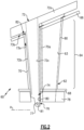
- Figure 2 illustrates a line representation of an example of a vane arc segment 60 from the turbine section 28 of the engine 20 (see also Figure 1 ). It is to be understood that although the examples herein are discussed in context of a vane from the turbine section, the examples can be applied to other vanes that have support spars.
- the vane arc segment 60 includes an airfoil fairing 62 that is formed by an airfoil wall 63.
- the airfoil fairing 62 is comprised of an airfoil section 64 and first and second platforms 66/68 between which the airfoil section 64 extends.
- the airfoil section 64 generally extends in a radial direction relative to the central engine axis A.
- Terms such as “inner” and “outer” used herein refer to location with respect to the central engine axis A, i.e., radially inner or radially outer.
- first and “second” used herein is to differentiate that there are two architecturally distinct components or features. It is to be further understood that the terms “first” and “second” are interchangeable in that a first component or feature could alternatively be termed as the second component or feature, and vice versa.
- the airfoil wall 63 is continuous in that the platforms 66/68 and airfoil section 64 constitute a unitary body.
- the airfoil wall 63 is formed of a ceramic matrix composite, an organic matrix composite (OMC), or a metal matrix composite (MMC).
- the ceramic matrix composite (CMC) is formed of ceramic fiber tows that are disposed in a ceramic matrix.
- the ceramic matrix composite may be, but is not limited to, a SiC/SiC ceramic matrix composite in which SiC fiber tows are disposed within a SiC matrix.
- Example organic matrix composites include, but are not limited to, glass fiber tows, carbon fiber tows, and/or aramid fiber tows disposed in a polymer matrix, such as epoxy.
- Example metal matrix composites include, but are not limited to, boron carbide fiber tows and/or alumina fiber tows disposed in a metal matrix, such as aluminum.
- a fiber tow is a bundle of filaments. As an example, a single tow may have several thousand filaments.
- the tows may be arranged in a fiber architecture, which refers to an ordered arrangement of the tows relative to one another, such as, but not limited to, a 2D woven ply or a 3D structure.
- the airfoil section 64 circumscribes an interior through-cavity 70.
- the airfoil section 64 may have a single through-cavity 70 or, as in the illustrated example, the cavity 70 may be divided by one or more ribs 70a into a forward sub-cavity and an aft sub-cavity.
- the vane arc segment 60 further includes a spar 72 that extends through the through-cavity 70 and mechanically supports the airfoil fairing 62.
- the spar 72 may be formed of a relatively high temperature resistance, high strength material, such as a single crystal metal alloy (e.g., a single crystal nickel- or cobalt-alloy).
- the spar 72 includes a spar platform 72a and a spar leg 72b that extends from the spar platform 72a into the through-cavity 70 (i.e., the forward sub-cavity in this example).
- the spar leg 72b is spaced from the airfoil wall 63 such that there is a first gap 73a between the airfoil wall 63 and the spar leg 72b. Cooling air may be provided into the first gap 73a to cool the airfoil wall 63.
- the spar platform 72a is spaced from the fairing platform 66 such that there is a second gap 73b there between.
- the spar platform 72a includes attachment features that secure it to a fixed support structure, such as an engine case.
- the spar leg 72b defines an interior through-passage 72c.
- the spar leg 72b has a distal end portion 74 that has a clevis mount 76.
- the end portion 74 of the spar leg 72b extends past the platform 68 of the airfoil fairing 62 so as to protrude from the fairing 62.
- the support platform 78, the platform 68 of the airfoil fairing 62, or both may have flanges or other mounting features through which the support platform 78 interfaces with the platform 68.
- the support platform 78 includes a through-hole 80 through which the end portion 74 of the spar leg 72b extends such that at least a portion of the clevis mount 76 protrudes from the support platform 78.
- the clevis mount 76 is comprised of two spaced-apart prongs that have aligned holes 77 through which a pin 81 extends.
- the pin 81 is wider than the through-hole 80 of the support platform 78. The ends of the pin 81 thus abut the face of the support platform 78 and thereby prevent the spar leg 72b from being retracted in the through-hole 80.
- the pin 81 thus locks the support platform 78 to the spar leg 72b such that the airfoil fairing 62 is mechanically trapped between the spar platform 72a and the support platform 78.
- the example configuration could be used at the outer end of the airfoil fairing 62, with the spar 72 being inverted such that the spar platform 72a is adjacent the platform 68 and the support platform 78 is adjacent the fairing platform 66.
- the illustrated example utilizes the clevis mount 76 to secure the spar leg 72b and support platform 78 together, other locking mechanisms may alternatively be used.
- the vane arc segment 60 also includes a baffle 80 that extends through the through-cavity 70 (i.e., the aft sub-cavity).
- the baffle 80 may have impingement holes for distributing cooling air onto the airfoil wall 63. If the through-cavity 70 does not contain any ribs and is only a single cavity, the baffle 80 is excluded, and if the through-cavity 70 contains multiple ribs 70a, additional baffles may be used.
- Cooling air such as bleed air from the compressor section 24, is conveyed into and through the through-passage 72c of the spar 72.
- This cooling air is destined for a downstream cooling location, such as a tangential onboard injector (TOBI). Cooling air may also be provided into the baffle 80 and the first gap 73a gap between the airfoil wall 63 and the spar leg 72b.
- the through-passage 72c of the spar leg 72b is fully or substantially fully isolated from the first gap 73a.
- the cooling air in the through-passage 72c does not intermix with cooling air in the first gap 73a.
- the cooling air provided to the first gap 73a and to the baffle 80 is fluidly isolated from the second gap 73b between the spar platform 72a and the fairing platform 66.
- the vane arc segment 60 includes a spring seal 82.
- the spring seal 82 serves dual functions in the vane arc segment 60. As indicated, the spring seal 82 first serves as a seal to isolate the first gap 73a from the second gap 73b and to isolate the aft sub-cavity of the through-cavity 70 from the second gap 73b.
- the spring seal 82 also serves to bias the airfoil fairing 62 toward the support platform 78.
- the biasing facilitates attenuation of radial tolerances in the assembly in that dimensional variations in the components is taken up by compression of the spring seal 82.
- the biasing also facilitates proper positioning of the components during assembly, idle, and engine shut-down by urging the airfoil fairing 62 toward the support platform 78.
- the biasing may also serve to constrain and position those seals.
- the spring seal 82 in the illustrated example is provided at the outer diameter of the airfoil fairing 62. It is to be understood, however, that the example configuration may be inverted such that the spring seal 82 is at the inner diameter. Moreover, it is also contemplated that spring seals 82 be provided at both the inner and outer diameter locations.
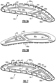
- Figure 3A illustrates an isometric view of an example spring seal 182 that may be used in the vane arc segment 60
- Figure 3B illustrates the spring seal 182 from the bottom.
- like reference numerals designate like elements where appropriate and reference numerals with the addition of one-hundred or multiples thereof designate modified elements that are understood to incorporate the same features and benefits of the corresponding elements.
- the spring seal 182 includes a seal plate 84 that defines an opening 86a through which the spar leg 72b extends.
- the spring seal 182 is also configured with an additional opening 86b through which the baffle 80 extends.
- the spring seal 82 would have only a single opening.
- the seal plate 84 includes a base plate 88 and a backing plate 90 that is bonded to the base plate 88.
- the plates 88/90 are metallic and are welded together, although brazing or other metallurgical attachment may alternatively be used.
- the plates 88/90 define a channel 92 that circumscribes the openings 86a/86b.
- the rope seal 94 is an endless ring, but may alternatively be a split ring in order to accommodate tight curvatures, for example.
- the base plate 88 defines a plurality of upstanding spring tabs 88a.
- the spring tabs 88a are spaced around the periphery of the base plate 88 so as to form a row that circumscribes the openings 86a/86b. As shown, the spring tabs 88a turn back so as to define an acute bend 88b, but obtuse bends may alternatively be utilized. The spring tabs 88a deflect at the bend 88b to provide the biasing discussed above. In this example, the spring tabs 88a also have hooked tips 88c that define bearing surfaces 88d.
- the spar leg 72b is received through the opening 86a of the spring seal 182.
- the spring tabs 88a contact the spar platform 72a such that the bearing surfaces 88d bear against the surface of the spar platform 72a.
- the backing plate 90 bears against the fairing platform 66 and thus provides a seal therewith.
- the base plate 88 and the backing plate 90 may be of the same or different thicknesses in order to tailor the performance. For instance, the thickness of the base plate 88 is used to tailor the spring constant of the spring tabs 88a, and the thickness of the backing plate 90 is used to tailor the ability of the backing plate 90 to deflect and conform against the fairing platform 66 for sealing.
- the rope seal 94 seals against the spar leg 72b in this example.
- the sealing of the rope seal 94 against the spar leg 72b and the sealing of the backing plate 90 against the fairing platform 66 isolates the first gap 73a from the second gap 73b.
- the spring seal 182 is clamped between the fairing platform 66 and the spar platform 72a, thereby compressing the spring tabs 88a to provide the aforementioned biasing.
- the baffle 80 is received through the opening 86b of the spring seal 182 such that the rope seal 94 seals against the baffle 80.
- FIG. 6 illustrates another example in which there is a baffle 96 around the spar leg 72b.
- the baffle 96 is disposed in the first gap 73a in the airfoil section 64.
- the spring seal 182 seals against the baffle 96.
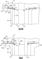
- FIG 7 illustrates another example spring seal 282 that is similar to the spring seal 182 except that the base plate 88 includes a plurality of through-holes 98 that open into the channel 92 behind the rope seal 94.
- cooling air provided to the base plate 88 on the side of the spar platform 72a flows though the through-holes 98.
- the cooling air is pressurized (e.g., bleed air from the compressor section 24) and biases the rope seal 94 against the spar leg 72b to facilitate good sealing between the rope seal 94 and the spar leg 72b.
- Figure 9 illustrates another example spring seal 382.
- the spring seal 382 is similar to the spring seal 182 except that the backing plate 190 in this example is larger than the backing plate 90 in the prior example such that the backing plate 190 has a skirt portion 190a.
- the skirt portion 190a extends outwardly beyond the base plate 88.
- the skirt portion 190a provides additional surface area for sealing with the fairing platform 66.
- the skirt portion 190a is, in essence, cantilevered from the base plate 88, there is less of a stiffening effect from the base plate 88 and the skirt portion 190a can thus be more compliant to seal against the fairing platform 66.
- the backing plate 190 (and/or the base plate 88) may include one or more projecting arms 97.
- the arm or arms 97 extend outwardly and overlap with an adjacent seal 99.
- the biasing force from the spring tabs 88a is transmitted though the arm 97 to exert a biasing force on the seal 99, thereby facilitating maintaining the seal 99 in place.
- the rope seal 94 is excluded.
- the sealing function is instead served by welding the edges of the base plate 88 and/or the backing plate 90 around the openings 86a/86b to the respective baffles 80/96.
- Figure 10 illustrates another example spring seal 482 falling outside the wording of the claims.
- the spring seal 482 does not have the backing plate 90 as in prior examples and instead only has the base plate 88.
- the channel 92 and rope seal 94 are eliminated.
- the sealing function is instead served by welding the edges of the base plate 88 around the openings 86a/86b at weld joints 101 to the respective baffles 80/96.
Landscapes
- Engineering & Computer Science (AREA)
- Mechanical Engineering (AREA)
- General Engineering & Computer Science (AREA)
- Chemical & Material Sciences (AREA)
- Ceramic Engineering (AREA)
- Materials Engineering (AREA)
- Turbine Rotor Nozzle Sealing (AREA)
- Structures Of Non-Positive Displacement Pumps (AREA)
Claims (11)
- Segment d'arc d'aube (60) comprenant :un carénage à profil aérodynamique (62) ayant une paroi de profil aérodynamique (63) définissant une plate-forme de carénage (66) et une section de profil aérodynamique creuse (64) s'étendant à partir de celle-ci ;un longeron (72) ayant une plate-forme de longeron (72a) adjacente à la plate-forme de carénage (66) et un pied de longeron (72b) qui s'étend depuis la plate-forme de longeron (72a) et à travers la section de profil aérodynamique creuse (64), le pied de longeron (72b) étant espacée de la paroi de profil aérodynamique (63) dans la section de profil aérodynamique creuse (64) de sorte qu'il y a un premier espace (73a) entre elles, et la plate-forme de longeron (72a) étant espacée de la plate-forme de carénage (66) de sorte qu'il y a un second espace (73b) entre eux ;une plate-forme de support (78) fixée au pied de longeron (72b) de sorte que le carénage aérodynamique (62) est coincé entre la plate-forme de longeron (72a) et la plate-forme de support (78) ; etun joint à ressort (82 ; 182 ; 282 ; 382 ; 482) entre la plate-forme de longeron (72a) et la plate-forme de carénage (66), le joint à ressort (82 ; 182 ; 282 ; 382 ; 482) sollicitant le carénage à profil aérodynamique (62) vers la plate-forme de support (78) et scellant le premier espace (73a) du second espace (73b),dans lequel le joint à ressort (82 ; 182 ; 282 ; 382 ; 482) comporte une plaque d'étanchéité (84) définissant une ouverture (86a) à travers laquelle s'étend le pied de longeron (72b),caractérisé en ce que :
la plaque d'étanchéité (84) comporte une plaque de base (88) et une plaque de support (90 ; 190) liée à la plaque de base (88), la plaque de support (90 ; 190) et la plaque de base (88) définissant un canal (92) qui circonscrit l'ouverture (86a) . - Segment d'arc d'aube (60) selon la revendication 1, dans lequel le joint à ressort (82 ; 182 ; 282 ; 382) comporte un joint à corde (94) disposé dans le canal (92).
- Segment d'arc d'aube (60) selon la revendication 1 ou 2, dans lequel la plaque de base (88) comporte une pluralité de trous traversants (98) qui débouchent dans le canal (92).
- Segment d'arc d'aube (60) selon une quelconque revendication précédente, dans lequel la plaque de base (88) définit une pluralité de pattes à ressort verticales (88a).
- Segment d'arc d'aube (60) selon la revendication 4, dans lequel chacune des pattes à ressort verticales (88a) comporte une pointe en crochet (88c) qui définit une surface d'appui (88d) .
- Segment d'arc d'aube (60) selon la revendication 4 ou 5, dans lequel chacune des pattes à ressort verticales (88a) présente une courbure aiguë (88b).
- Segment d'arc d'aube (60) selon l'une quelconque des revendications 4 à 6, dans lequel les pattes à ressort verticales (88a) s'appuient contre la plate-forme de longeron (72a) et la plaque de support (90 ; 190) s'appuie contre la plate-forme de carénage (66).
- Segment d'arc d'aube (60) selon une quelconque revendication précédente, dans lequel la plaque de support (190) comporte une partie jupe (190a) qui, par rapport à l'ouverture (86a), s'étend vers l'extérieur au-delà de la plaque de base (88).
- Segment d'arc d'aube (60) selon une quelconque revendication précédente, dans lequel la plaque d'étanchéité (84) comporte un bras saillant (97) qui chevauche un joint adjacent supplémentaire (99).
- Segment d'arc d'aube (60) selon une quelconque revendication précédente, dans lequel la plaque d'étanchéité (84) définit une seconde ouverture (86b) à travers laquelle s'étend un déflecteur (80), et la plaque d'étanchéité (84) est soudée au déflecteur (80) autour de la seconde ouverture (86b) .
- Moteur à turbine à gaz (20) comprenant :une section de compresseur (24) ;une chambre de combustion (26) en communication fluidique avec la section de compresseur (24) ; etune section de turbine (28) en communication fluidique avec la chambre de combustion (26), la section de turbine (28) ayant des segment d'arc d'aube (60) disposées autour d'un axe central (A) du moteur à turbine à gaz (20), chacun des segments d'arc d'aube (60) comprenant le segment d'arc d'aube (60) selon une quelconque revendication précédente.
Priority Applications (1)
| Application Number | Priority Date | Filing Date | Title |
|---|---|---|---|
| EP24192714.4A EP4431703A3 (fr) | 2021-03-03 | 2022-03-03 | Segment d'arc d'aube avec joint d'étanchéité à ressort |
Applications Claiming Priority (1)
| Application Number | Priority Date | Filing Date | Title |
|---|---|---|---|
| US17/191,152 US11506069B2 (en) | 2021-03-03 | 2021-03-03 | Vane arc segment with spring seal |
Related Child Applications (1)
| Application Number | Title | Priority Date | Filing Date |
|---|---|---|---|
| EP24192714.4A Division EP4431703A3 (fr) | 2021-03-03 | 2022-03-03 | Segment d'arc d'aube avec joint d'étanchéité à ressort |
Publications (3)
| Publication Number | Publication Date |
|---|---|
| EP4063618A2 EP4063618A2 (fr) | 2022-09-28 |
| EP4063618A3 EP4063618A3 (fr) | 2022-12-07 |
| EP4063618B1 true EP4063618B1 (fr) | 2024-08-07 |
Family
ID=80628658
Family Applications (2)
| Application Number | Title | Priority Date | Filing Date |
|---|---|---|---|
| EP24192714.4A Pending EP4431703A3 (fr) | 2021-03-03 | 2022-03-03 | Segment d'arc d'aube avec joint d'étanchéité à ressort |
| EP22160037.2A Active EP4063618B1 (fr) | 2021-03-03 | 2022-03-03 | Segment d'arc d'aube doté d'un joint à ressort |
Family Applications Before (1)
| Application Number | Title | Priority Date | Filing Date |
|---|---|---|---|
| EP24192714.4A Pending EP4431703A3 (fr) | 2021-03-03 | 2022-03-03 | Segment d'arc d'aube avec joint d'étanchéité à ressort |
Country Status (2)
| Country | Link |
|---|---|
| US (1) | US11506069B2 (fr) |
| EP (2) | EP4431703A3 (fr) |
Families Citing this family (2)
| Publication number | Priority date | Publication date | Assignee | Title |
|---|---|---|---|---|
| US11549385B2 (en) * | 2021-05-04 | 2023-01-10 | Raytheon Technologies Corporation | Airfoil assembly with seal plate and seal |
| JP2023172520A (ja) * | 2022-05-24 | 2023-12-06 | 三菱重工業株式会社 | タービン静翼及びガスタービン |
Family Cites Families (15)
| Publication number | Priority date | Publication date | Assignee | Title |
|---|---|---|---|---|
| US6042334A (en) * | 1998-08-17 | 2000-03-28 | General Electric Company | Compressor interstage seal |
| US6296443B1 (en) | 1999-12-03 | 2001-10-02 | General Electric Company | Vane sector seating spring and method of retaining same |
| US7824152B2 (en) | 2007-05-09 | 2010-11-02 | Siemens Energy, Inc. | Multivane segment mounting arrangement for a gas turbine |
| US8899914B2 (en) * | 2012-01-05 | 2014-12-02 | United Technologies Corporation | Stator vane integrated attachment liner and spring damper |
| JP6021675B2 (ja) * | 2013-02-13 | 2016-11-09 | 三菱重工業株式会社 | 燃焼器のシール構造及び燃焼器用シール |
| WO2016068857A1 (fr) * | 2014-10-28 | 2016-05-06 | Siemens Aktiengesellschaft | Ensemble joint d'étanchéité entre un conduit de transition et l'ensemble d'aubes de première rangée à utiliser dans des moteurs à turbine |
| EP3032034B1 (fr) * | 2014-12-12 | 2019-11-27 | United Technologies Corporation | Insert à dispersion de jets, aube statorique ayant un insert à dispersion de jets, et procédé de fabrication associé d'une aube statorique |
| US10443417B2 (en) | 2015-09-18 | 2019-10-15 | General Electric Company | Ceramic matrix composite ring shroud retention methods-finger seals with stepped shroud interface |
| US10233764B2 (en) * | 2015-10-12 | 2019-03-19 | Rolls-Royce North American Technologies Inc. | Fabric seal and assembly for gas turbine engine |
| US10208614B2 (en) | 2016-02-26 | 2019-02-19 | General Electric Company | Apparatus, turbine nozzle and turbine shroud |
| US10428663B2 (en) | 2016-11-17 | 2019-10-01 | United Technologies Corporation | Airfoil with tie member and spring |
| US10767497B2 (en) | 2018-09-07 | 2020-09-08 | Rolls-Royce Corporation | Turbine vane assembly with ceramic matrix composite components |
| US10767495B2 (en) | 2019-02-01 | 2020-09-08 | Rolls-Royce Plc | Turbine vane assembly with cooling feature |
| US10890076B1 (en) | 2019-06-28 | 2021-01-12 | Rolls-Royce Plc | Turbine vane assembly having ceramic matrix composite components with expandable spar support |
| US11346234B2 (en) * | 2020-01-02 | 2022-05-31 | Rolls-Royce Plc | Turbine vane assembly incorporating ceramic matrix composite materials |
-
2021
- 2021-03-03 US US17/191,152 patent/US11506069B2/en active Active
-
2022
- 2022-03-03 EP EP24192714.4A patent/EP4431703A3/fr active Pending
- 2022-03-03 EP EP22160037.2A patent/EP4063618B1/fr active Active
Also Published As
| Publication number | Publication date |
|---|---|
| US20220282630A1 (en) | 2022-09-08 |
| EP4431703A3 (fr) | 2024-12-18 |
| EP4063618A3 (fr) | 2022-12-07 |
| EP4063618A2 (fr) | 2022-09-28 |
| EP4431703A2 (fr) | 2024-09-18 |
| US11506069B2 (en) | 2022-11-22 |
Similar Documents
| Publication | Publication Date | Title |
|---|---|---|
| EP3779131B1 (fr) | Agencement de composant de passage d'écoulement et section de turbine associée pour un moteur à turbine à gaz | |
| EP3792453B1 (fr) | Ensemble boas cmc | |
| EP3786419A1 (fr) | Agencement boas à matrice céramique | |
| EP3971391B1 (fr) | Aube de turbine à gaz en cmc avec longeron de support et déflecteur avec refroidissement par impact | |
| EP3805530B1 (fr) | Joint à l'air extérieur d'aubes pour moteur à turbine à gaz et procédé d'assemblage ou de démontage correspondant | |
| US12025020B2 (en) | Vane system with continuous support ring | |
| US11486256B2 (en) | Vane arc segment with conformal thermal insulation blanket | |
| EP4063618B1 (fr) | Segment d'arc d'aube doté d'un joint à ressort | |
| EP4030036B1 (fr) | Segment d'arc d'aube directrice avec plate-forme de support avec canal radial incurvé | |
| EP4053379B1 (fr) | Segment d'arc d'aube doté d'un longeron avec carénage à goupille | |
| EP4053377B1 (fr) | Segment d'arc d'aube comportant un joint | |
| EP4015773B1 (fr) | Vanne avec déflecteur et longeron encastré | |
| EP4086432B1 (fr) | Aube directrice avec support de broche et déflecteur anti-rotation | |
| EP4033071B1 (fr) | Vanne avec support de broche et anti-rotation | |
| EP4056814B1 (fr) | Ensemble aube comportant un dispositif à ressort pour étanchéisation de joint de face de couplage | |
| EP4080018B1 (fr) | Segment d'arc d'aube avec bride à échelon et procédé de fabrication d'un segment d'aube | |
| US11125099B2 (en) | Boas arrangement with double dovetail attachments |
Legal Events
| Date | Code | Title | Description |
|---|---|---|---|
| PUAI | Public reference made under article 153(3) epc to a published international application that has entered the european phase |
Free format text: ORIGINAL CODE: 0009012 |
|
| STAA | Information on the status of an ep patent application or granted ep patent |
Free format text: STATUS: THE APPLICATION HAS BEEN PUBLISHED |
|
| AK | Designated contracting states |
Kind code of ref document: A2 Designated state(s): AL AT BE BG CH CY CZ DE DK EE ES FI FR GB GR HR HU IE IS IT LI LT LU LV MC MK MT NL NO PL PT RO RS SE SI SK SM TR |
|
| PUAL | Search report despatched |
Free format text: ORIGINAL CODE: 0009013 |
|
| AK | Designated contracting states |
Kind code of ref document: A3 Designated state(s): AL AT BE BG CH CY CZ DE DK EE ES FI FR GB GR HR HU IE IS IT LI LT LU LV MC MK MT NL NO PL PT RO RS SE SI SK SM TR |
|
| RIC1 | Information provided on ipc code assigned before grant |
Ipc: F01D 9/04 20060101ALI20221103BHEP Ipc: F01D 5/28 20060101ALI20221103BHEP Ipc: F01D 5/18 20060101AFI20221103BHEP |
|
| STAA | Information on the status of an ep patent application or granted ep patent |
Free format text: STATUS: REQUEST FOR EXAMINATION WAS MADE |
|
| 17P | Request for examination filed |
Effective date: 20230607 |
|
| RBV | Designated contracting states (corrected) |
Designated state(s): AL AT BE BG CH CY CZ DE DK EE ES FI FR GB GR HR HU IE IS IT LI LT LU LV MC MK MT NL NO PL PT RO RS SE SI SK SM TR |
|
| RAP3 | Party data changed (applicant data changed or rights of an application transferred) |
Owner name: RTX CORPORATION |
|
| GRAP | Despatch of communication of intention to grant a patent |
Free format text: ORIGINAL CODE: EPIDOSNIGR1 |
|
| STAA | Information on the status of an ep patent application or granted ep patent |
Free format text: STATUS: GRANT OF PATENT IS INTENDED |
|
| INTG | Intention to grant announced |
Effective date: 20240229 |
|
| GRAS | Grant fee paid |
Free format text: ORIGINAL CODE: EPIDOSNIGR3 |
|
| GRAA | (expected) grant |
Free format text: ORIGINAL CODE: 0009210 |
|
| STAA | Information on the status of an ep patent application or granted ep patent |
Free format text: STATUS: THE PATENT HAS BEEN GRANTED |
|
| AK | Designated contracting states |
Kind code of ref document: B1 Designated state(s): AL AT BE BG CH CY CZ DE DK EE ES FI FR GB GR HR HU IE IS IT LI LT LU LV MC MK MT NL NO PL PT RO RS SE SI SK SM TR |
|
| REG | Reference to a national code |
Ref country code: GB Ref legal event code: FG4D |
|
| REG | Reference to a national code |
Ref country code: CH Ref legal event code: EP |
|
| REG | Reference to a national code |
Ref country code: DE Ref legal event code: R096 Ref document number: 602022005055 Country of ref document: DE |
|
| REG | Reference to a national code |
Ref country code: IE Ref legal event code: FG4D |
|
| REG | Reference to a national code |
Ref country code: LT Ref legal event code: MG9D |
|
| REG | Reference to a national code |
Ref country code: NL Ref legal event code: MP Effective date: 20240807 |
|
| PG25 | Lapsed in a contracting state [announced via postgrant information from national office to epo] |
Ref country code: NO Free format text: LAPSE BECAUSE OF FAILURE TO SUBMIT A TRANSLATION OF THE DESCRIPTION OR TO PAY THE FEE WITHIN THE PRESCRIBED TIME-LIMIT Effective date: 20241107 |
|
| REG | Reference to a national code |
Ref country code: AT Ref legal event code: MK05 Ref document number: 1711149 Country of ref document: AT Kind code of ref document: T Effective date: 20240807 |
|
| PG25 | Lapsed in a contracting state [announced via postgrant information from national office to epo] |
Ref country code: FI Free format text: LAPSE BECAUSE OF FAILURE TO SUBMIT A TRANSLATION OF THE DESCRIPTION OR TO PAY THE FEE WITHIN THE PRESCRIBED TIME-LIMIT Effective date: 20240807 Ref country code: NL Free format text: LAPSE BECAUSE OF FAILURE TO SUBMIT A TRANSLATION OF THE DESCRIPTION OR TO PAY THE FEE WITHIN THE PRESCRIBED TIME-LIMIT Effective date: 20240807 Ref country code: PL Free format text: LAPSE BECAUSE OF FAILURE TO SUBMIT A TRANSLATION OF THE DESCRIPTION OR TO PAY THE FEE WITHIN THE PRESCRIBED TIME-LIMIT Effective date: 20240807 Ref country code: PT Free format text: LAPSE BECAUSE OF FAILURE TO SUBMIT A TRANSLATION OF THE DESCRIPTION OR TO PAY THE FEE WITHIN THE PRESCRIBED TIME-LIMIT Effective date: 20241209 Ref country code: GR Free format text: LAPSE BECAUSE OF FAILURE TO SUBMIT A TRANSLATION OF THE DESCRIPTION OR TO PAY THE FEE WITHIN THE PRESCRIBED TIME-LIMIT Effective date: 20241108 |
|
| PG25 | Lapsed in a contracting state [announced via postgrant information from national office to epo] |
Ref country code: BG Free format text: LAPSE BECAUSE OF FAILURE TO SUBMIT A TRANSLATION OF THE DESCRIPTION OR TO PAY THE FEE WITHIN THE PRESCRIBED TIME-LIMIT Effective date: 20240807 |
|
| PG25 | Lapsed in a contracting state [announced via postgrant information from national office to epo] |
Ref country code: LV Free format text: LAPSE BECAUSE OF FAILURE TO SUBMIT A TRANSLATION OF THE DESCRIPTION OR TO PAY THE FEE WITHIN THE PRESCRIBED TIME-LIMIT Effective date: 20240807 |
|
| PG25 | Lapsed in a contracting state [announced via postgrant information from national office to epo] |
Ref country code: AT Free format text: LAPSE BECAUSE OF FAILURE TO SUBMIT A TRANSLATION OF THE DESCRIPTION OR TO PAY THE FEE WITHIN THE PRESCRIBED TIME-LIMIT Effective date: 20240807 Ref country code: IS Free format text: LAPSE BECAUSE OF FAILURE TO SUBMIT A TRANSLATION OF THE DESCRIPTION OR TO PAY THE FEE WITHIN THE PRESCRIBED TIME-LIMIT Effective date: 20241207 |
|
| PG25 | Lapsed in a contracting state [announced via postgrant information from national office to epo] |
Ref country code: HR Free format text: LAPSE BECAUSE OF FAILURE TO SUBMIT A TRANSLATION OF THE DESCRIPTION OR TO PAY THE FEE WITHIN THE PRESCRIBED TIME-LIMIT Effective date: 20240807 |
|
| PG25 | Lapsed in a contracting state [announced via postgrant information from national office to epo] |
Ref country code: RS Free format text: LAPSE BECAUSE OF FAILURE TO SUBMIT A TRANSLATION OF THE DESCRIPTION OR TO PAY THE FEE WITHIN THE PRESCRIBED TIME-LIMIT Effective date: 20241107 Ref country code: ES Free format text: LAPSE BECAUSE OF FAILURE TO SUBMIT A TRANSLATION OF THE DESCRIPTION OR TO PAY THE FEE WITHIN THE PRESCRIBED TIME-LIMIT Effective date: 20240807 |
|
| PG25 | Lapsed in a contracting state [announced via postgrant information from national office to epo] |
Ref country code: RS Free format text: LAPSE BECAUSE OF FAILURE TO SUBMIT A TRANSLATION OF THE DESCRIPTION OR TO PAY THE FEE WITHIN THE PRESCRIBED TIME-LIMIT Effective date: 20241107 Ref country code: PT Free format text: LAPSE BECAUSE OF FAILURE TO SUBMIT A TRANSLATION OF THE DESCRIPTION OR TO PAY THE FEE WITHIN THE PRESCRIBED TIME-LIMIT Effective date: 20241209 Ref country code: PL Free format text: LAPSE BECAUSE OF FAILURE TO SUBMIT A TRANSLATION OF THE DESCRIPTION OR TO PAY THE FEE WITHIN THE PRESCRIBED TIME-LIMIT Effective date: 20240807 Ref country code: NO Free format text: LAPSE BECAUSE OF FAILURE TO SUBMIT A TRANSLATION OF THE DESCRIPTION OR TO PAY THE FEE WITHIN THE PRESCRIBED TIME-LIMIT Effective date: 20241107 Ref country code: NL Free format text: LAPSE BECAUSE OF FAILURE TO SUBMIT A TRANSLATION OF THE DESCRIPTION OR TO PAY THE FEE WITHIN THE PRESCRIBED TIME-LIMIT Effective date: 20240807 Ref country code: LV Free format text: LAPSE BECAUSE OF FAILURE TO SUBMIT A TRANSLATION OF THE DESCRIPTION OR TO PAY THE FEE WITHIN THE PRESCRIBED TIME-LIMIT Effective date: 20240807 Ref country code: IS Free format text: LAPSE BECAUSE OF FAILURE TO SUBMIT A TRANSLATION OF THE DESCRIPTION OR TO PAY THE FEE WITHIN THE PRESCRIBED TIME-LIMIT Effective date: 20241207 Ref country code: HR Free format text: LAPSE BECAUSE OF FAILURE TO SUBMIT A TRANSLATION OF THE DESCRIPTION OR TO PAY THE FEE WITHIN THE PRESCRIBED TIME-LIMIT Effective date: 20240807 Ref country code: GR Free format text: LAPSE BECAUSE OF FAILURE TO SUBMIT A TRANSLATION OF THE DESCRIPTION OR TO PAY THE FEE WITHIN THE PRESCRIBED TIME-LIMIT Effective date: 20241108 Ref country code: FI Free format text: LAPSE BECAUSE OF FAILURE TO SUBMIT A TRANSLATION OF THE DESCRIPTION OR TO PAY THE FEE WITHIN THE PRESCRIBED TIME-LIMIT Effective date: 20240807 Ref country code: ES Free format text: LAPSE BECAUSE OF FAILURE TO SUBMIT A TRANSLATION OF THE DESCRIPTION OR TO PAY THE FEE WITHIN THE PRESCRIBED TIME-LIMIT Effective date: 20240807 Ref country code: BG Free format text: LAPSE BECAUSE OF FAILURE TO SUBMIT A TRANSLATION OF THE DESCRIPTION OR TO PAY THE FEE WITHIN THE PRESCRIBED TIME-LIMIT Effective date: 20240807 Ref country code: AT Free format text: LAPSE BECAUSE OF FAILURE TO SUBMIT A TRANSLATION OF THE DESCRIPTION OR TO PAY THE FEE WITHIN THE PRESCRIBED TIME-LIMIT Effective date: 20240807 |
|
| PG25 | Lapsed in a contracting state [announced via postgrant information from national office to epo] |
Ref country code: DK Free format text: LAPSE BECAUSE OF FAILURE TO SUBMIT A TRANSLATION OF THE DESCRIPTION OR TO PAY THE FEE WITHIN THE PRESCRIBED TIME-LIMIT Effective date: 20240807 Ref country code: SM Free format text: LAPSE BECAUSE OF FAILURE TO SUBMIT A TRANSLATION OF THE DESCRIPTION OR TO PAY THE FEE WITHIN THE PRESCRIBED TIME-LIMIT Effective date: 20240807 |
|
| PG25 | Lapsed in a contracting state [announced via postgrant information from national office to epo] |
Ref country code: EE Free format text: LAPSE BECAUSE OF FAILURE TO SUBMIT A TRANSLATION OF THE DESCRIPTION OR TO PAY THE FEE WITHIN THE PRESCRIBED TIME-LIMIT Effective date: 20240807 |
|
| PG25 | Lapsed in a contracting state [announced via postgrant information from national office to epo] |
Ref country code: CZ Free format text: LAPSE BECAUSE OF FAILURE TO SUBMIT A TRANSLATION OF THE DESCRIPTION OR TO PAY THE FEE WITHIN THE PRESCRIBED TIME-LIMIT Effective date: 20240807 |
|
| PG25 | Lapsed in a contracting state [announced via postgrant information from national office to epo] |
Ref country code: SK Free format text: LAPSE BECAUSE OF FAILURE TO SUBMIT A TRANSLATION OF THE DESCRIPTION OR TO PAY THE FEE WITHIN THE PRESCRIBED TIME-LIMIT Effective date: 20240807 |
|
| REG | Reference to a national code |
Ref country code: DE Ref legal event code: R097 Ref document number: 602022005055 Country of ref document: DE |
|
| PLBE | No opposition filed within time limit |
Free format text: ORIGINAL CODE: 0009261 |
|
| STAA | Information on the status of an ep patent application or granted ep patent |
Free format text: STATUS: NO OPPOSITION FILED WITHIN TIME LIMIT |
|
| 26N | No opposition filed |
Effective date: 20250508 |
|
| PG25 | Lapsed in a contracting state [announced via postgrant information from national office to epo] |
Ref country code: SE Free format text: LAPSE BECAUSE OF FAILURE TO SUBMIT A TRANSLATION OF THE DESCRIPTION OR TO PAY THE FEE WITHIN THE PRESCRIBED TIME-LIMIT Effective date: 20240807 |
|
| PG25 | Lapsed in a contracting state [announced via postgrant information from national office to epo] |
Ref country code: MC Free format text: LAPSE BECAUSE OF FAILURE TO SUBMIT A TRANSLATION OF THE DESCRIPTION OR TO PAY THE FEE WITHIN THE PRESCRIBED TIME-LIMIT Effective date: 20240807 |
|
| REG | Reference to a national code |
Ref country code: CH Ref legal event code: H13 Free format text: ST27 STATUS EVENT CODE: U-0-0-H10-H13 (AS PROVIDED BY THE NATIONAL OFFICE) Effective date: 20251023 |
|
| PG25 | Lapsed in a contracting state [announced via postgrant information from national office to epo] |
Ref country code: LU Free format text: LAPSE BECAUSE OF NON-PAYMENT OF DUE FEES Effective date: 20250303 |
|
| REG | Reference to a national code |
Ref country code: BE Ref legal event code: MM Effective date: 20250331 |
|
| PG25 | Lapsed in a contracting state [announced via postgrant information from national office to epo] |
Ref country code: BE Free format text: LAPSE BECAUSE OF NON-PAYMENT OF DUE FEES Effective date: 20250331 |
|
| PG25 | Lapsed in a contracting state [announced via postgrant information from national office to epo] |
Ref country code: CH Free format text: LAPSE BECAUSE OF NON-PAYMENT OF DUE FEES Effective date: 20250331 |
|
| PG25 | Lapsed in a contracting state [announced via postgrant information from national office to epo] |
Ref country code: IE Free format text: LAPSE BECAUSE OF NON-PAYMENT OF DUE FEES Effective date: 20250303 |
|
| PG25 | Lapsed in a contracting state [announced via postgrant information from national office to epo] |
Ref country code: IT Free format text: LAPSE BECAUSE OF FAILURE TO SUBMIT A TRANSLATION OF THE DESCRIPTION OR TO PAY THE FEE WITHIN THE PRESCRIBED TIME-LIMIT Effective date: 20240807 |
|
| PGFP | Annual fee paid to national office [announced via postgrant information from national office to epo] |
Ref country code: GB Payment date: 20260220 Year of fee payment: 5 |
|
| PGFP | Annual fee paid to national office [announced via postgrant information from national office to epo] |
Ref country code: DE Payment date: 20260219 Year of fee payment: 5 |
|
| PG25 | Lapsed in a contracting state [announced via postgrant information from national office to epo] |
Ref country code: RO Free format text: LAPSE BECAUSE OF FAILURE TO SUBMIT A TRANSLATION OF THE DESCRIPTION OR TO PAY THE FEE WITHIN THE PRESCRIBED TIME-LIMIT Effective date: 20240807 |
|
| PGFP | Annual fee paid to national office [announced via postgrant information from national office to epo] |
Ref country code: FR Payment date: 20260220 Year of fee payment: 5 |